EP2290719A1 - Piezoelectric element and audio equipment - Google Patents
Piezoelectric element and audio equipment Download PDFInfo
- Publication number
- EP2290719A1 EP2290719A1 EP09746444A EP09746444A EP2290719A1 EP 2290719 A1 EP2290719 A1 EP 2290719A1 EP 09746444 A EP09746444 A EP 09746444A EP 09746444 A EP09746444 A EP 09746444A EP 2290719 A1 EP2290719 A1 EP 2290719A1
- Authority
- EP
- European Patent Office
- Prior art keywords
- piezoelectric
- sheet
- piezoelectric element
- sheets
- piezoelectric sheet
- Prior art date
- Legal status (The legal status is an assumption and is not a legal conclusion. Google has not performed a legal analysis and makes no representation as to the accuracy of the status listed.)
- Granted
Links
- 229920000747 poly(lactic acid) Polymers 0.000 claims abstract description 21
- 239000004626 polylactic acid Substances 0.000 claims abstract description 21
- 229920000642 polymer Polymers 0.000 claims description 22
- 239000000470 constituent Substances 0.000 claims description 13
- XLOMVQKBTHCTTD-UHFFFAOYSA-N Zinc monoxide Chemical compound [Zn]=O XLOMVQKBTHCTTD-UHFFFAOYSA-N 0.000 claims description 10
- 229920000123 polythiophene Polymers 0.000 claims description 8
- 239000011787 zinc oxide Substances 0.000 claims description 5
- AMGQUBHHOARCQH-UHFFFAOYSA-N indium;oxotin Chemical compound [In].[Sn]=O AMGQUBHHOARCQH-UHFFFAOYSA-N 0.000 claims description 4
- OYQCBJZGELKKPM-UHFFFAOYSA-N zinc indium(3+) oxygen(2-) Chemical compound [O-2].[Zn+2].[O-2].[In+3] OYQCBJZGELKKPM-UHFFFAOYSA-N 0.000 claims description 4
- 238000006073 displacement reaction Methods 0.000 description 27
- 230000005684 electric field Effects 0.000 description 27
- 229920001432 poly(L-lactide) Polymers 0.000 description 23
- JVTAAEKCZFNVCJ-REOHCLBHSA-N L-lactic acid Chemical compound C[C@H](O)C(O)=O JVTAAEKCZFNVCJ-REOHCLBHSA-N 0.000 description 20
- 238000010586 diagram Methods 0.000 description 9
- 239000010408 film Substances 0.000 description 8
- 238000000034 method Methods 0.000 description 6
- 239000000178 monomer Substances 0.000 description 5
- 229920005989 resin Polymers 0.000 description 5
- 239000011347 resin Substances 0.000 description 5
- 230000001413 cellular effect Effects 0.000 description 4
- 239000000463 material Substances 0.000 description 3
- 238000004544 sputter deposition Methods 0.000 description 3
- 230000015572 biosynthetic process Effects 0.000 description 2
- 239000011248 coating agent Substances 0.000 description 2
- 238000000576 coating method Methods 0.000 description 2
- JVTAAEKCZFNVCJ-UHFFFAOYSA-N lactic acid Chemical compound CC(O)C(O)=O JVTAAEKCZFNVCJ-UHFFFAOYSA-N 0.000 description 2
- 230000003068 static effect Effects 0.000 description 2
- OKTJSMMVPCPJKN-UHFFFAOYSA-N Carbon Chemical compound [C] OKTJSMMVPCPJKN-UHFFFAOYSA-N 0.000 description 1
- JOYRKODLDBILNP-UHFFFAOYSA-N Ethyl urethane Chemical compound CCOC(N)=O JOYRKODLDBILNP-UHFFFAOYSA-N 0.000 description 1
- WHUUTDBJXJRKMK-UHFFFAOYSA-N Glutamic acid Natural products OC(=O)C(N)CCC(O)=O WHUUTDBJXJRKMK-UHFFFAOYSA-N 0.000 description 1
- WHUUTDBJXJRKMK-VKHMYHEASA-N L-glutamic acid Chemical compound OC(=O)[C@@H](N)CCC(O)=O WHUUTDBJXJRKMK-VKHMYHEASA-N 0.000 description 1
- 229920002472 Starch Polymers 0.000 description 1
- 230000000903 blocking effect Effects 0.000 description 1
- 229910052799 carbon Inorganic materials 0.000 description 1
- 238000006243 chemical reaction Methods 0.000 description 1
- 238000005034 decoration Methods 0.000 description 1
- 230000000694 effects Effects 0.000 description 1
- 229920001971 elastomer Polymers 0.000 description 1
- 239000000806 elastomer Substances 0.000 description 1
- 239000003822 epoxy resin Substances 0.000 description 1
- 235000013922 glutamic acid Nutrition 0.000 description 1
- 239000004220 glutamic acid Substances 0.000 description 1
- 229960000448 lactic acid Drugs 0.000 description 1
- 235000014655 lactic acid Nutrition 0.000 description 1
- 239000004310 lactic acid Substances 0.000 description 1
- 229910052751 metal Inorganic materials 0.000 description 1
- 239000002184 metal Substances 0.000 description 1
- 244000005700 microbiome Species 0.000 description 1
- 239000000203 mixture Substances 0.000 description 1
- 230000003287 optical effect Effects 0.000 description 1
- 239000011368 organic material Substances 0.000 description 1
- 238000007747 plating Methods 0.000 description 1
- 229920000647 polyepoxide Polymers 0.000 description 1
- 238000006116 polymerization reaction Methods 0.000 description 1
- 229920001296 polysiloxane Polymers 0.000 description 1
- 229920002050 silicone resin Polymers 0.000 description 1
- 235000019698 starch Nutrition 0.000 description 1
- 239000008107 starch Substances 0.000 description 1
- 229920003048 styrene butadiene rubber Polymers 0.000 description 1
- 238000003786 synthesis reaction Methods 0.000 description 1
- 239000010409 thin film Substances 0.000 description 1
- 238000007740 vapor deposition Methods 0.000 description 1
- 239000002699 waste material Substances 0.000 description 1
Images


Classifications
-
- H—ELECTRICITY
- H04—ELECTRIC COMMUNICATION TECHNIQUE
- H04R—LOUDSPEAKERS, MICROPHONES, GRAMOPHONE PICK-UPS OR LIKE ACOUSTIC ELECTROMECHANICAL TRANSDUCERS; DEAF-AID SETS; PUBLIC ADDRESS SYSTEMS
- H04R17/00—Piezoelectric transducers; Electrostrictive transducers
- H04R17/005—Piezoelectric transducers; Electrostrictive transducers using a piezoelectric polymer
-
- H—ELECTRICITY
- H10—SEMICONDUCTOR DEVICES; ELECTRIC SOLID-STATE DEVICES NOT OTHERWISE PROVIDED FOR
- H10N—ELECTRIC SOLID-STATE DEVICES NOT OTHERWISE PROVIDED FOR
- H10N30/00—Piezoelectric or electrostrictive devices
- H10N30/20—Piezoelectric or electrostrictive devices with electrical input and mechanical output, e.g. functioning as actuators or vibrators
- H10N30/204—Piezoelectric or electrostrictive devices with electrical input and mechanical output, e.g. functioning as actuators or vibrators using bending displacement, e.g. unimorph, bimorph or multimorph cantilever or membrane benders
- H10N30/2041—Beam type
- H10N30/2042—Cantilevers, i.e. having one fixed end
-
- H—ELECTRICITY
- H10—SEMICONDUCTOR DEVICES; ELECTRIC SOLID-STATE DEVICES NOT OTHERWISE PROVIDED FOR
- H10N—ELECTRIC SOLID-STATE DEVICES NOT OTHERWISE PROVIDED FOR
- H10N30/00—Piezoelectric or electrostrictive devices
- H10N30/80—Constructional details
- H10N30/85—Piezoelectric or electrostrictive active materials
- H10N30/857—Macromolecular compositions
-
- H—ELECTRICITY
- H04—ELECTRIC COMMUNICATION TECHNIQUE
- H04R—LOUDSPEAKERS, MICROPHONES, GRAMOPHONE PICK-UPS OR LIKE ACOUSTIC ELECTROMECHANICAL TRANSDUCERS; DEAF-AID SETS; PUBLIC ADDRESS SYSTEMS
- H04R17/00—Piezoelectric transducers; Electrostrictive transducers
- H04R17/02—Microphones
- H04R17/025—Microphones using a piezoelectric polymer
-
- Y—GENERAL TAGGING OF NEW TECHNOLOGICAL DEVELOPMENTS; GENERAL TAGGING OF CROSS-SECTIONAL TECHNOLOGIES SPANNING OVER SEVERAL SECTIONS OF THE IPC; TECHNICAL SUBJECTS COVERED BY FORMER USPC CROSS-REFERENCE ART COLLECTIONS [XRACs] AND DIGESTS
- Y10—TECHNICAL SUBJECTS COVERED BY FORMER USPC
- Y10S—TECHNICAL SUBJECTS COVERED BY FORMER USPC CROSS-REFERENCE ART COLLECTIONS [XRACs] AND DIGESTS
- Y10S310/00—Electrical generator or motor structure
- Y10S310/80—Piezoelectric polymers, e.g. PVDF
Definitions
- the present invention relates to a piezoelectric element and an audio device, and in particular, to a piezoelectric element including a piezoelectric sheet made of a polymer, which exhibits piezoelectricity when it is stretched, such as a polylactic acid, and an audio device configured with the use of piezoelectric element.
- Patent Document 1 discloses a piezoelectric sheet with a piezoelectric constant d 14 , which can be obtained by stretching a molded product of a polylactic acid. More specifically, as shown in FIG. 16 , assuming that a piezoelectric sheet 11 made of a polylactic acid has electrodes formed on upper and lower surfaces in the figure and is stretched in a "3" axis direction, stain will be produced in a "4" axis direction which is the rotating direction of "1" axis, when an electric field is applied in the direction of the "1" axis which is a normal direction with respect to the electrode surfaces.
- This piezoelectric sheet made of a polylactic acid is used to provide a unimorph or bimorph structure, thereby allowing piezoelectric elements such as piezoelectric vibrators to be obtained for use in speakers, microphones, etc.
- Patent Document 1 discloses these applications, it merely mentions that "when the molded object stretched is a film, the film is cut into an appropriate size to serve as a product" (section [0018]) and includes no specific disclosure on the method for constituting the piezoelectric elements.
- the stretched sheet has the problem of tendency to tear along the stretching direction.
- the tendency to tear will be alleviated to some extent.
- the substantially uniaxial stretching by four to six times has to be obtained in order to keep high piezoelectricity. Therefore, in the case of biaxial stretching in the X axis direction and the Y axis direction, the ratio of the stretching in the Y axis direction to the stretching in the X axis direction has to be set to 1:4 to 1:6. For example, when biaxial stretching is to be carried out in the X axis direction, the stretching by 8 times or more has to be carried out in the Y axis direction.
- an object of the present invention is to provide a piezoelectric element including a piezoelectric sheet, which can solve the problem as described above, and an audio device configured with the use of the piezoelectric element.
- the present invention is directed to a piezoelectric element including a plurality of stacked piezoelectric sheets having a predetermined stretching axis and having a main constituent including a helical polymer with a chiral molecule as a unit, and electrodes formed on both principal surfaces of each of the piezoelectric sheets.
- the present invention has a feature in that at least one piezoelectric sheet of the plurality of piezoelectric sheets is different from the other piezoelectric sheet in the direction of the stretching axis.
- the “stretching axis” refers to the axis oriented in the direction of the stretching in the case of uniaxial stretching
- the “stretching axis” refers to the axis oriented in the direction of the stretching with the maximum stretch ratio in the case of stretching in multiple directions, as in the case of biaxial stretching.
- the stretching axis of at least one piezoelectric sheet of the plurality of piezoelectric sheets forms an angle of 90 degrees with the stretching axis of the other piezoelectric sheet. It is preferable to form an angle close to 90 degrees as much as possible even if the angle is other than 90 degrees.
- the piezoelectric sheets are rectangular.
- one side of the piezoelectric sheet forms an angle of greater than 0 degrees and less than 90 degrees with the stretching axis, more preferably an angle of 25 degrees or more and 65 degrees or less, and most preferably an angle of 45 degrees.
- the plurality of piezoelectric sheets include first and second piezoelectric sheets which are adjacent to each other with respect to the stacking direction and different from each other in the direction of the stretching axis, and an insulating layer is formed between the first piezoelectric sheet and the second piezoelectric sheet in order to electrically isolate the electrode formed on the principal surface of the first piezoelectric sheet and the electrode formed on the principal surface of the second piezoelectric sheet from each other.
- the plurality of piezoelectric sheets include a first piezoelectric sheet with the stretching axis oriented in a first direction and a second piezoelectric sheet with the stretching axis oriented in a second direction different from the first direction, first and second intermediate laminates are configured by alternately stacking the first piezoelectric sheet and the second piezoelectric sheet.
- the first and second intermediate laminates are stacked in such a way that the first piezoelectric sheets or the second piezoelectric sheets are adjacent to each other.
- the helical polymer constituting the piezoelectric sheets is preferably a polylactic acid.
- the electrodes preferably contain, as their main constituent, an indium tin oxide, an indium oxide-zinc oxide, or a zinc oxide.
- the electrodes preferably contain, as their main constituent, a polythiophene.
- the present invention is also directed to an audio device including the piezoelectric element according to the present invention as described above.
- At least one piezoelectric sheet of the plurality of piezoelectric sheets is different from the other piezoelectric sheet in the direction of the stretching axis, and the strength of a piezoelectric sheet in a direction along which the piezoelectric sheet tends to tear is thus reinforced by the other piezoelectric sheet, thereby increasing the strength of the plurality of piezoelectric sheets as a laminate.
- the stretching axis of at least one piezoelectric sheet forms an angle of 90 degrees with the stretching axis of the other piezoelectric sheet, the maximum strength can be obtained.
- the amplitude in the case of applying an electric field can be dramatically increased as compared with the case with the angle of 0 degrees or 90 degrees. More definitely, when one side of the piezoelectric sheet forms an angle of 25 degrees or more and 65 degrees or less with the stretching axis, a higher amplitude can be obtained, and further, when one side of the piezoelectric sheet forms an angle of 45 degrees, the maximum amplitude can be obtained.
- a piezoelectric element can be configured by simply stacking the two piezoelectric sheets of the first and second dielectric sheets.
- the plurality of piezoelectric sheets include a first piezoelectric sheet with the stretching axis oriented in a first direction and a second piezoelectric sheet with the stretching axis oriented in a second direction different from the first direction
- first and second intermediate laminates are configured by alternately stacking the first piezoelectric sheet and the second piezoelectric sheet, and when the first and second intermediate laminates are stacked in such a way that the first piezoelectric sheets or the second piezoelectric sheets are adjacent to each other
- the electric field intensity onto each of the piezoelectric sheets can be increased without increasing the applied voltage, thereby allowing the strain forces of the piezoelectric sheets themselves to be increased and allowing the amounts of displacement thereof to be increased.
- a polylactic acid as a helical polymer constituting the piezoelectric sheets allows piezoelectric sheets with excellent transparency to be obtained.
- the polylactic acid can achieve stable piezoelectric characteristics, and provide piezoelectric elements in an inexpensive way.
- the polylactic acid is also preferable in terms of protection of the global environment, because the polylactic acid is carbon-neutral and biodegradable.
- the piezoelectric element can be made transparent as long as the piezoelectric sheets have transparency.
- the use of the polylactic acid for the piezoelectric sheets makes it possible to make the piezoelectric element almost completely transparent, because the polylactic acid has an extremely high degree of transparency.
- the polythiophene allows deformations or vibrations of the piezoelectric sheets to be prevented from being substantially inhibited, because the polythiophene is a polymer with softness.
- the electrodes containing the polythiophene as their main constituent require no cumbersome and costly steps such as sputtering, and can be formed in an inexpensive way through a simple step such as simple coating.
- a transparent speaker for example, can be configured. This type of speaker can be placed even on the surface of a display without blocking a line of vision.
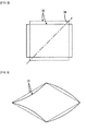
- the piezoelectric sheet 11 with the piezoelectric constant d 14 , shown in FIG. 16 is shown in a plan view of FIG. 17 , in a rectangular shape cut out with the direction of one side of the piezoelectric element 11 corresponding to the direction of a stretching axis 12 thereof.
- a voltage is applied so as to keep an electrode (not shown) on a front principal surface, with respect to the plane of paper, of the piezoelectric sheet 12 shown in FIG. 17 at, for example, 0 V, and keep an electrode (not shown) of a back principal surface with respect to the plane of paper at, for example, 10 V
- the piezoelectric sheet 12 is deformed from the original state indicated by a dashed line to a state indicated by a solid line in FIG. 17 .
- FIG. 18 is a cross-sectional view illustrating a portion of a bimorph type piezoelectric element 15 configured by stacking two piezoelectric sheets as described above.
- the bimorph type piezoelectric element 15 has a structure of two piezoelectric sheets 16 and 17 attached, with an electrode 18 formed on the outward principal surface of the piezoelectric sheet 16, an electrode 19 formed on the respective inward principal surfaces of the piezoelectric sheets 16 and 17 between the piezoelectric sheets 16 and 17, and an electrode 20 formed on the outward principal surface of the piezoelectric sheet 17. It is to be noted that while the thicknesses of the electrodes 18 to 20 are quite small actually as compared with the thicknesses of the piezoelectric sheets 16 and 17, the electrodes 18 to 20 are shown exaggeratingly in FIG. 18 .
- the respective stretching axes 21 and 22 of the two piezoelectric sheets 16 and 17 are oriented in the same direction as each other.
- the bimorph type piezoelectric element 15 shown in FIG. 18 is intended to serve as a reference example outside the scope of the present invention.
- a relatively plus electric potential for example, 10 V
- a relatively minus electric potential for example, 0 V
- an electric field 23 applied to the piezoelectric sheet 16 is oppositely oriented with respect to an electric field 24 applied to the piezoelectric sheet 17, and as seen with a predetermined direction as a standard, the piezoelectric sheets 16 and 17 behave in such a way that one of the piezoelectric sheets 16 and 17 stretches whereas the other contracts. As a result, a deformation is caused as shown in FIG. 19 .
- the bimorph type piezoelectric element 15 when the bimorph type piezoelectric element 15 is fixed with one side of the bimorph type piezoelectric element 15 as a fixed end 25, the bimorph type piezoelectric element 15 will cause a deformation as shown in FIG. 20 . Then, when an alternating current voltage is applied for the electric fields 23 and 24, the bimorph type piezoelectric element 15 will vibrate.
- the vibration in this mode is not preferable as bimorph vibration, and exhibits a small amount of displacement, because the amount of displacement is substantially 0 in a central portion of the side of the bimorph type piezoelectric element 15 opposed to the fixed end 25.
- the electrodes 18 to 20 are simple in structure in the bimorph type piezoelectric element 15, the respective stretching axes 21 and 22 of the two piezoelectric sheets 16 and 17 are oriented in the same direction as each other as described above, and the bimorph type piezoelectric element 15 thus has a problem in that the piezoelectric sheets tend to tear along the stretching axes.
- FIG. 1 shows a bimorph type piezoelectric element 31 as a piezoelectric element according to a first embodiment of the present invention, where FIG. 1(a) is a plan view, FIG. 1(b) is a front view, and FIG. 1(c) is a cross-sectional view illustrating an enlarged section C of FIG. 1(b) .
- the bimorph type piezoelectric element 31 has a structure of two piezoelectric sheets 32 and 33 attached, which are each made of a polylactic acid. As shown in FIG. 1(c) , an electrode 34 is formed on the outward principal surface of the piezoelectric sheet 32, whereas an electrode 35 is formed on the inward principal surface of the piezoelectric sheet 32. In addition, an electrode 36 is formed on the inward principal surface of the piezoelectric sheet 33, whereas an electrode 37 is formed on the outward principal surface of the piezoelectric sheet 33. In addition, the electrode 35 and the electrode 36 are attached to each other so as to be electrically isolated from each other with an insulating layer 38 interposed therebetween.
- the piezoelectric sheets 32 and 33 made of a polylactic acid as described above make it possible to provide stable piezoelectric characteristics and excellent transparency for the piezoelectric sheets 32 and 33.
- a helical polymer containing a main constituent with a chiral molecule as a unit, other than the polylactic acid may be used as the material for the dielectric sheets 32 and 33.
- polymers from a monomer with chirality do not always have a helical structure.
- one of polymers with enantiomerism is referred to as an L isomer, whereas the other is referred to as a D isomer.
- the L isomer provides a helical polymer
- the D isomer also provides a helical polymer, and the helical directions are opposite to each other.
- a polymer of a mixture of a polymer from the L isomer and a polymer from the D isomer exhibits neither optical rotation nor piezoelectricity, because the polymers are reversed with each other.
- a monomer of glutamic acid or lactic acid has an asymmetric carbon, and thus has chirality, and further provides a helical polymer (chiral polymer).
- the electrodes 34 to 37 are preferably made of a material containing as its main constituent an indium tin oxide, an indium oxide-zinc oxide, or a zinc oxide. Since these materials have transparency, the bimorph type piezoelectric element 31 can be provided with transparency as long as the piezoelectric sheets 32 and 33 have transparency. In particular, when the piezoelectric sheets 32 and 33 are made of a polylactic acid, the bimorph type piezoelectric element 31 can provide a high degree of transparency.
- the electrodes 34 to 37 preferably contain polythiophene as its main constituent.
- the polythiophene allows, because of its softness, deformations or vibrations of the piezoelectric sheets 32 and 33 to be prevented from being substantially inhibited.
- simple coating can be applied in the case of using an organic material
- sputtering can be applied in the case of using a zinc oxide or the like
- vapor deposition, sputtering, plating, bonding of a thin film, etc. can be applied in the case of a metal.
- the insulating layer 38 is preferably made of a transparent and flexible resin.
- a transparent and flexible resin for example, an epoxy resin, a silicone resin, a styrene-butadiene copolymer, etc. can be used. It is to be noted that even if the resin itself constituting the insulating layer 38 has a low degree of transparency, the insulating layer 38 can be, because of its extreme thinness, provided with substantial transparency, but the resin itself constituting the insulating layer 38 preferably has a high degree of transparency.
- FIGS. 1(a) and (c) a stretching axis 39 of the piezoelectric sheet 32 and a stretching axis 40 of the piezoelectric sheet 33 are shown.
- These stretching axes 39 and 40 refer to the axes oriented in the stretching directions provided to the piezoelectric sheets 32 and 33, and refer to the axes oriented in the directions of stretching with the maximum stretch ratios in the case of stretching in multiple directions, for example, as in the case of biaxial stretching.
- the bimorph type piezoelectric element 31 is characterized in that the stretching axis 39 of the piezoelectric sheet 32 and the stretching axis 40 of the piezoelectric sheet 33 are different in direction from each other.
- the stretching axis 39 of the piezoelectric sheet 32 forms an angle of 90 degrees with the stretching axis 40 of the piezoelectric sheet 33. This allows the bimorph type piezoelectric element 31 to produce the maximum strength against the tendency to tear along the stretching directions.
- the stretched piezoelectric sheets 32 and 33 have birefringence. Therefore, when light passing through the piezoelectric sheet 32 or 33 is split into two linear polarized beams orthogonal to each other, a phase difference is caused between the two linear polarized beams. As a result, when an object is seen through the piezoelectric sheet 32 or 33, the image may blur in some cases.
- the phase difference between the two linear polarized beams is eliminated to cause the birefringence of the bimorph type piezoelectric element 31 itself to disappear. Accordingly, when an object is seen through the bimorph type piezoelectric element 31, the image will not blur.
- the piezoelectric sheets 32 and 33 have a rectangular shape, and more particularly, a square shape, one side of each of the piezoelectric sheets 32 and 33 forms an angle of 45 degrees with each of the stretching axes 39 and 40. Therefore, as will be described in detail later, the maximum amplitude can be obtained.
- the piezoelectric sheet 32 When one of the piezoelectric sheets 32 and 33, for example, only the piezoelectric sheet 32 is picked up, with a voltage applied to keep the electrode 34 at, for example, 0 V and keep the electrode 35 at, for example, 10 V, a deformation is caused as shown in FIG. 2 . More specifically, the piezoelectric sheet 32 is deformed from the original state indicated by a dashed line to a state indicated by a solid line in FIG. 2 . More simply, the piezoelectric sheet 32 is deformed so as to stretch and contract broadly in a direction with ⁇ 45 degrees with respect to the stretching axis 39.
- FIGS. 3 and 4 show a deformation or a vibration of the bimorph type piezoelectric element 31.
- the bimorph type piezoelectric element 31 is obtained by attaching the piezoelectric sheet 32 for causing a deformation as shown in FIG. 2 and the piezoelectric sheet 33 for causing a similar deformation to each other, and the stretching axes 39 and 40 of the respective piezoelectric sheets 32 and 33 are orthogonal to each other.
- a relatively plus electric potential for example, 10 V
- a relatively minus electric potential for example, 0 V
- the bimorph type piezoelectric element 31 is capable of producing a large amount of displacement.
- the problem of the tendency to tear along the stretching axes can be avoided, because the respective stretching axes 39 and 40 of the two dielectric sheets 32 and 33 are oriented in different directions from each other as previously described.
- FIG. 5 is a diagram for explaining a preferable method for cutting out the piezoelectric sheets 32 and 33 for the bimorph type piezoelectric element 31 from a mother piezoelectric sheet 46.
- FIG. 5 shows the mother piezoelectric sheet 46 with a stretching axis 47 in a plan view. From this mother piezoelectric sheet 46, the one piezoelectric sheet 32 is cut out with its long axis 48 oriented at 45 degrees with respect to the stretching axis 47, whereas the other piezoelectric sheet 33 is cut out with its long axis 49 oriented at -45 degrees with respect to the stretching axis 47. Then, as long as the piezoelectric sheet 32 and piezoelectric sheet 33 cut out in this way are stacked to overlap with each other, the stretching axis 39 of the piezoelectric sheet 32 and the stretching axis 40 of the piezoelectric sheet 33 can be made orthogonal to each other.
- the piezoelectric sheets 32 and 33 cut out from the mother piezoelectric sheet 46 each have a rectangular shape rather than a square shape, in order to determine the direction of stacking the piezoelectric sheet 32 and the piezoelectric sheet 33 without making a mistake. Therefore, in order to obtain the bimorph type piezoelectric element 31 in a square shape as shown in FIG. 1(a) , the piezoelectric sheets 32 and 33 may be attached to each other, and then cut to have a square shape. In addition, depending on the cutting mode, bimorph type piezoelectric elements can be obtained which have any shapes other than the rectangle.
- the maximum amplitude is obtained when one side of the rectangular piezoelectric sheet forms an angle of 45 degrees with respect to the stretching axis, and a study will be made on how the amplitude is changed when the angle between the one side of the piezoelectric sheet and the stretching axis is changed.
- FIG. 6 shows a bimorph type piezoelectric element 51 subjected to the study described above, where FIG. 6(a) is a plan view, and FIG. 6(b) is an enlarged cross-sectional view.
- the bimorph type piezoelectric element 51 has two PLLA sheets 52 and 53. Electrodes 54 and 55 are formed respectively on each principal surface of the one PLLA sheet 52, whereas electrodes 56 and 57 are respectively formed on each principal surface of the other PLLA sheet 53. In addition, an insulating layer 58 is formed between the electrode 55 and the electrode 56.
- the respective stretching axes 59 and 60 of the two PLLA sheets 52 and 53 are oriented in the same direction as each other.
- the bimorph type piezoelectric element 51 shown in FIG. 6 falls outside the scope of the present invention. It is to be noted that when it is not necessary to distinguish the stretching axis 59 and stretching axis 60 oriented in the same direction from each other, the both are representatively referred to as the "stretching axis 59" in the following description.
- FIG. 7 shows displacement obtained by performing static analysis calculations in accordance with the finite element method while, with one side of this bimorph type piezoelectric element 51 as a fixed end 61, varying the angle ⁇ formed by a normal 62 for the fixed end 61 and the stretching axis 59 within the range of 0 to 90 degrees. It is to be noted that the angle ⁇ is equal to the angle formed by one side of each of the PLLA sheets 52 and 53 and the stretching axis 59, because the normal 62 extends parallel to one side of each of the PLLA sheets 52 and 53.
- the displacement shown in FIG. 7 is displacement obtained in a central portion of the side opposed to the fixed end 61 of the bimorph type piezoelectric element 51.
- an alternating current voltage of 30 V was applied to the electrodes 54 to 57 in such a way that an electric field 63 applied to the PLLA sheet 52 and an electric field 64 applied to the PLLA sheet 53 are oriented in opposite directions to each other, as shown in FIG. 6(b) .
- each of the electrodes 54 to 57 is regarded as an ideal electrode with a thickness of 0.
- the maximum displacement is exhibited when the angle ⁇ formed by the normal 62 and the stretching axis 59 is 45 degrees.
- the angle ⁇ falls within the range of 25 degrees to 65 degrees, about 90% or more of the maximum displacement is ensured.
- the angle ⁇ is greater than 0 degrees and less than 90 degrees, the displacement is dramatically increased as compared with the case of 0 degrees or 90 degrees.
- FIG. 8 is a diagram illustrating a bimorph type piezoelectric element 51 subjected to the study described above, which corresponds to FIG. 6 .
- the same reference numbers are assigned to elements corresponding to the elements shown in FIG. 6 , and overlapped descriptions of the elements will be omitted.
- the first PLLA sheet 52 and the second PLLA sheet 53 are stacked in such a way that the stretching axis 59 of the first PLLA sheet 52 forms an angle of ⁇ 1 with the normal 62 and the stretching axis 60 of the second PLLA sheet 53 forms an angle of ⁇ 2 with the normal 62.
- FIG. 9 shows the results of static analysis calculations in accordance with the finite element method for the relationships between the angles ⁇ 1 and ⁇ and the displacement.
- FIG. 10 is a diagram illustrating FIG. 9 in a two-dimensional way.
- the darkest shaded area refers to an area which includes a point indicating the maximum displacement of the bimorph type piezoelectric element 51 and is capable of ensuring about 90% or more of the maximum displacement.
- the amount of displacement of the bimorph type piezoelectric element 51 is almost proportional to the magnitude of the voltage applied. Therefore, as long as there is an area which provides about 90% or more of the maximum displacement, it is possible to deal with the lacking amount of displacement by increasing the driving voltage, and typically, it is possible to adequately handle this increase in driving voltage with the use of remaining power from a driving power source.
- the minimum and maximum of ⁇ 1 - ⁇ 2 are respectively 66 degrees and 114 degrees, and in the case of 114 degrees, the subtraction of 114 degrees from 180 degrees definitely results in the same value as 66 degrees.
- the value of 66 degrees is sufficiently large as compared with 0 degrees leading to the minimum strength, and thus considered to be an angle at which the problem of the PLLA sheets 52 and 53 tearing along the stretching axes 59 and 60 can be avoided adequately.
- the preferable range in terms of amplitude and strength can be said to be present in the area in which the angles ⁇ 1 and ⁇ 2 satisfy the equation (3).
- the displacement of a piezoelectric sheet made of a polylactic acid or the like is increased with increase in electric field intensity applied thereto. While the applied voltage may be increased in order to increase the electric field intensity applied to the piezoelectric sheet, it is difficult to achieve high voltages in the case of mounting the piezoelectric element onto a mobile device or the like. Thus, since the electric field intensity is proportional to the voltage and inversely proportional to the distance between electrodes, the electric field intensity onto the piezoelectric sheet is increased when the piezoelectric sheet is reduced in thickness. However, if the piezoelectric sheet is reduced in thickness too much, the strain force of the piezoelectric sheet itself may overwhelmed by the strength of the electrodes, resulting in the inability to achieve desired strain.
- the bimorph refers to an element of a stretchable piezoelectric sheet and a contractable piezoelectric sheet stacked for producing displacement, and one bimorph has only one boundary between the stretchable piezoelectric sheet and the contractable piezoelectric sheet. Therefore, it is conceivable that a stack structure made of multiple piezoelectric sheets is adopted for a stretchable piezoelectric sheet section and/or a contractable piezoelectric sheet section in order to increase the strain force of the piezoelectric sheets themselves, even while reducing the piezoelectric sheets in thickness in order to increase the electric field intensity onto the piezoelectric sheets.
- FIG. 11 which takes the measure described above, is a diagram illustrating a bimorph type piezoelectric element 71 according to the second embodiment of the present invention, which corresponds to FIG. 1(c) .
- the bimorph type piezoelectric element 71 includes a first piezoelectric sheet 73 with a stretching axis 72 oriented in a first direction and a second piezoelectric sheet 75 with a stretching axis 74 oriented in a second direction different from the first direction. Further, more preferably, the stretching axis 72 and the stretching axis 74 are orthogonal to each other.
- piezoelectric sheets 73 and 75 described above constitute first and second intermediate laminates 76 and 77
- first piezoelectric sheet 73 and the second piezoelectric sheet 75 are alternately stacked in each case of the first and second intermediate laminates 76 and 77.
- the first and second intermediate laminates 76 and 77 are stacked in such a way that the first piezoelectric sheets 73 or the second piezoelectric sheets 75 are adjacent to each other. In the embodiment shown, the first and second intermediate laminates 76 and 77 are stacked in such a way that the second piezoelectric sheets 75 are adjacent to each other.
- electrodes 78 to 82 are respectively formed between the first and second piezoelectric sheets 73 and 75 and on the outward principal surfaces of the first and second piezoelectric sheets 73 and 75.
- the electrodes 78, 80, and 82 are kept at the same electric potential as each other, whereas the electrodes 79 and 81 are kept at the same electric potential as each other, which are different from the electric potential for the electrodes 78, 80, and 82.
- the bimorph type piezoelectric element 71 generally undergoes a deflection with the electrode 80 section as a boundary, and vibrates as a bimorph when an alternating current voltage is applied.
- each of the first and second intermediate laminates 76 and 77 is made of the two piezoelectric sheets 73 and 75 in the embodiment shown in FIG. 11
- at least one of the first and second intermediate laminates 76 and 77 may be made of three or more piezoelectric sheets.
- the piezoelectric sheets provided for each of the first and second intermediate laminates desirably have the same thickness as each other, and while the first and second intermediate laminates desirably have the same number of stacked piezoelectric sheets as each other, it is not always necessary to adopt the same thickness and the same number of stacked piezoelectric sheets.
- one of the first and second intermediate laminates may be simply made of a single piezoelectric sheet.
- the electric fields onto each of the piezoelectric sheets 73 and 75 can be increased without increasing the applied voltage, and as a result, both the strain force and the amount of displacement can be increased for each of the piezoelectric sheets 73 and 75 themselves.
- an insulating layer corresponding to the insulating layer 38 shown in FIG. 1(c) is not required in this embodiment.
- the bimorph type piezoelectric element 31 according to the first embodiment as described with reference to FIGS. 1 to 4 causes deformations as described in FIG. 3 , and this bimorph type piezoelectric element 31 can be thus attached onto a film made of a stretchable elastomer (for example, an urethane based film, a silicone based film) to allows for serving as a speaker.
- a stretchable elastomer for example, an urethane based film, a silicone based film
- FIG. 12 is a front view illustrating a speaker 91 configured with the use of the bimorph type piezoelectric element 31.
- the bimorph type piezoelectric element 31 is attached onto a stretchable film 92, and the film 92 is fixed in a fixture section 93 in the shape of a frame.
- the speaker 91 shown in FIG. 12 can be configured to have transparency, because the bimorph type piezoelectric element 31 can be made transparent as previously described, and the speaker 91 can be totally made transparent because components such as an exciter are not required. Therefore, even when the speaker is placed directly on a display surface 96 of a portable game machine 95 shown in FIG. 14 or a display surface 99 of a cellular phone 95 shown in FIG 15 , the image under the speaker can be made clearly visible. Likewise, the speaker can also be placed on display surfaces of electronic dictionaries, electronic diaries, personal computers, televisions, etc.
- the piezoelectric sheets constituting the piezoelectric element are made of a resin, and thus will not be broken by normal impacts. Therefore, the piezoelectric sheets are advantageously applied in portable devices such as portable game machines and cellular phones.
- the piezoelectric sheets made of a resin are flexible, and thus applicable to, for example, paper displays using organic EL, etc.
- the speaker can be made transparent, which can be placed directly on display surfaces. Therefore, the area of the speaker can be increased to improve the sound quality.
- conventional built-in speakers can be eliminated, and as a result, the devices can be reduced in size or new functional components can be built in the spaces with the built-in speakers removed, thereby allowing for enhancement in the performance of the devices.
- the speaker made transparent according to the present invention can be advantageously directed to the following applications.
- the attachment of the speaker to a window near the priority seat of a train, a bus, or the like also makes it easier for elderly people to listen to announcements in the train, bus, or the like, and moreover, will not cut off the view from the window of the train, bus, or the like.
- message cards such as premium Christmas cards have been popular.
- the speaker can be used as a speaker serving as decoration.
- the speaker when the speaker is attached to an advertisement on the wall surface, in particular, a face part of an advertisement with a person arranged to produce the content to be advertised as sounds as if the person were speaking, the interest of people can be attracted to increase the advertising effectiveness.
- it is further effective to combine the speaker with an infrared sensor or a Doppler sensor so as to call (stop) people when the people come closer.
- the present invention can be applied to not only bimorph type piezoelectric elements but also other piezoelectric elements.
Abstract
Description
- The present invention relates to a piezoelectric element and an audio device, and in particular, to a piezoelectric element including a piezoelectric sheet made of a polymer, which exhibits piezoelectricity when it is stretched, such as a polylactic acid, and an audio device configured with the use of piezoelectric element.
- Japanese Patent Application Laid-Open No.
5-152638 FIG. 16 , assuming that apiezoelectric sheet 11 made of a polylactic acid has electrodes formed on upper and lower surfaces in the figure and is stretched in a "3" axis direction, stain will be produced in a "4" axis direction which is the rotating direction of "1" axis, when an electric field is applied in the direction of the "1" axis which is a normal direction with respect to the electrode surfaces. - This piezoelectric sheet made of a polylactic acid is used to provide a unimorph or bimorph structure, thereby allowing piezoelectric elements such as piezoelectric vibrators to be obtained for use in speakers, microphones, etc. While Patent Document 1 discloses these applications, it merely mentions that "when the molded object stretched is a film, the film is cut into an appropriate size to serve as a product" (section [0018]) and includes no specific disclosure on the method for constituting the piezoelectric elements.
- On the other hand, the stretched sheet has the problem of tendency to tear along the stretching direction. In this case, if biaxial stretching is carried out, the tendency to tear will be alleviated to some extent. It is to be noted that the substantially uniaxial stretching by four to six times has to be obtained in order to keep high piezoelectricity. Therefore, in the case of biaxial stretching in the X axis direction and the Y axis direction, the ratio of the stretching in the Y axis direction to the stretching in the X axis direction has to be set to 1:4 to 1:6. For example, when biaxial stretching is to be carried out in the X axis direction, the stretching by 8 times or more has to be carried out in the Y axis direction.
- However, even when the biaxial stretching is carried out as described above, the problem of the tendency to tear will still remain while the problem is alleviated to some extent. In particular, in the case of using the piezoelectric sheet for actuators, speakers, etc., the problem of the tendency to tear is serious because the piezoelectric sheet always has relatively high stress caused.
- Further, this problem is encountered not only for piezoelectric sheets made of a polylactic acid, but also generally for piezoelectric sheets which have a main constituent made of a helical polymer with a chiral molecule as a unit and exhibit piezoelectricity when they are stretched.
-
- Patent Document 1: Japanese Patent Application Laid-Open No.
5-152638 - Therefore, an object of the present invention is to provide a piezoelectric element including a piezoelectric sheet, which can solve the problem as described above, and an audio device configured with the use of the piezoelectric element.
- The present invention is directed to a piezoelectric element including a plurality of stacked piezoelectric sheets having a predetermined stretching axis and having a main constituent including a helical polymer with a chiral molecule as a unit, and electrodes formed on both principal surfaces of each of the piezoelectric sheets. In order to solve the above technical problem, the present invention has a feature in that at least one piezoelectric sheet of the plurality of piezoelectric sheets is different from the other piezoelectric sheet in the direction of the stretching axis.
- It is to be noted that while the "stretching axis" refers to the axis oriented in the direction of the stretching in the case of uniaxial stretching, the "stretching axis" refers to the axis oriented in the direction of the stretching with the maximum stretch ratio in the case of stretching in multiple directions, as in the case of biaxial stretching.
- In the piezoelectric element according to the present invention, it is more preferable that the stretching axis of at least one piezoelectric sheet of the plurality of piezoelectric sheets forms an angle of 90 degrees with the stretching axis of the other piezoelectric sheet. It is preferable to form an angle close to 90 degrees as much as possible even if the angle is other than 90 degrees.
- Typically, the piezoelectric sheets are rectangular. In this case, preferably one side of the piezoelectric sheet forms an angle of greater than 0 degrees and less than 90 degrees with the stretching axis, more preferably an angle of 25 degrees or more and 65 degrees or less, and most preferably an angle of 45 degrees.
- According to a first preferred aspect, in the piezoelectric element according to the present invention, the plurality of piezoelectric sheets include first and second piezoelectric sheets which are adjacent to each other with respect to the stacking direction and different from each other in the direction of the stretching axis, and an insulating layer is formed between the first piezoelectric sheet and the second piezoelectric sheet in order to electrically isolate the electrode formed on the principal surface of the first piezoelectric sheet and the electrode formed on the principal surface of the second piezoelectric sheet from each other.
- According to a second preferred aspect, in the piezoelectric element according to the present invention, the plurality of piezoelectric sheets include a first piezoelectric sheet with the stretching axis oriented in a first direction and a second piezoelectric sheet with the stretching axis oriented in a second direction different from the first direction, first and second intermediate laminates are configured by alternately stacking the first piezoelectric sheet and the second piezoelectric sheet. The first and second intermediate laminates are stacked in such a way that the first piezoelectric sheets or the second piezoelectric sheets are adjacent to each other.
- The helical polymer constituting the piezoelectric sheets is preferably a polylactic acid.
- The electrodes preferably contain, as their main constituent, an indium tin oxide, an indium oxide-zinc oxide, or a zinc oxide. Alternatively, the electrodes preferably contain, as their main constituent, a polythiophene.
- The present invention is also directed to an audio device including the piezoelectric element according to the present invention as described above.
- In the piezoelectric element according to the present invention, at least one piezoelectric sheet of the plurality of piezoelectric sheets is different from the other piezoelectric sheet in the direction of the stretching axis, and the strength of a piezoelectric sheet in a direction along which the piezoelectric sheet tends to tear is thus reinforced by the other piezoelectric sheet, thereby increasing the strength of the plurality of piezoelectric sheets as a laminate. In particular, when the stretching axis of at least one piezoelectric sheet forms an angle of 90 degrees with the stretching axis of the other piezoelectric sheet, the maximum strength can be obtained.
- When the piezoelectric sheet is rectangular, and when one side of the piezoelectric sheet forms an angle of greater than 0 degrees and less than 90 degrees with the stretching axis, the amplitude in the case of applying an electric field can be dramatically increased as compared with the case with the angle of 0 degrees or 90 degrees. More definitely, when one side of the piezoelectric sheet forms an angle of 25 degrees or more and 65 degrees or less with the stretching axis, a higher amplitude can be obtained, and further, when one side of the piezoelectric sheet forms an angle of 45 degrees, the maximum amplitude can be obtained.
- When the plurality of piezoelectric sheets include first and second piezoelectric sheets which are adjacent to each other with respect to the stacking direction and different from each other in the direction of the stretching axis, and when an insulating layer is formed between the first piezoelectric sheet and the second piezoelectric sheet in order to electrically isolate the electrode formed on the principal surface of the first piezoelectric sheet and the electrode formed on the principal surface of the second piezoelectric sheet from each other, a piezoelectric element can be configured by simply stacking the two piezoelectric sheets of the first and second dielectric sheets.
- When the plurality of piezoelectric sheets include a first piezoelectric sheet with the stretching axis oriented in a first direction and a second piezoelectric sheet with the stretching axis oriented in a second direction different from the first direction, when first and second intermediate laminates are configured by alternately stacking the first piezoelectric sheet and the second piezoelectric sheet, and when the first and second intermediate laminates are stacked in such a way that the first piezoelectric sheets or the second piezoelectric sheets are adjacent to each other, the electric field intensity onto each of the piezoelectric sheets can be increased without increasing the applied voltage, thereby allowing the strain forces of the piezoelectric sheets themselves to be increased and allowing the amounts of displacement thereof to be increased.
- The use of a polylactic acid as a helical polymer constituting the piezoelectric sheets allows piezoelectric sheets with excellent transparency to be obtained. In addition, the polylactic acid can achieve stable piezoelectric characteristics, and provide piezoelectric elements in an inexpensive way. Furthermore, the polylactic acid is also preferable in terms of protection of the global environment, because the polylactic acid is carbon-neutral and biodegradable.
- When the electrodes contain, as their main constituent, an indium tin oxide, an indium oxide-zinc oxide, or a zinc oxide, the piezoelectric element can be made transparent as long as the piezoelectric sheets have transparency. In particular, the use of the polylactic acid for the piezoelectric sheets makes it possible to make the piezoelectric element almost completely transparent, because the polylactic acid has an extremely high degree of transparency.
- When the electrodes contain, as their main constituent, a polythiophene, the polythiophene allows deformations or vibrations of the piezoelectric sheets to be prevented from being substantially inhibited, because the polythiophene is a polymer with softness. In addition, the electrodes containing the polythiophene as their main constituent require no cumbersome and costly steps such as sputtering, and can be formed in an inexpensive way through a simple step such as simple coating.
- When the piezoelectric element according to the present invention is used to constitute an audio device, a transparent speaker, for example, can be configured. This type of speaker can be placed even on the surface of a display without blocking a line of vision.
-
-
FIG. 1 shows a bimorph typepiezoelectric element 31 as a piezoelectric element according to a first embodiment of the present invention, whereFIG. 1(a) is a plan view,FIG. 1(b) is a front view, andFIG. 1(c) is a cross-sectional view illustrating an enlarged section C ofFIG. 1(b) . -
FIG. 2 is a plan view illustrating a deformed mode of apiezoelectric sheet 32 shown inFIG. 1 in the case of applying an electric field. -
FIG. 3 is a perspective view illustrating a deformed mode of the bimorph typepiezoelectric element 31 shown inFIG. 1 in the case of applying an electric field. -
FIG. 4 is a perspective view illustrating a deformed mode with one side of the bimorph typepiezoelectric element 31 shown inFIG. 1 as a fixedend 43 in the case of applying an electric field. -
FIG. 5 is a plan view for explaining a preferable method for cutting out thepiezoelectric sheets FIG. 1 from a motherpiezoelectric sheet 46. -
FIG. 6 shows a bimorph typepiezoelectric element 51 configured by attaching twoPLLA sheets FIG. 6(a) is a plan view, andFIG. 6(b) is an enlarged cross-sectional view. -
FIG. 7 is a diagram illustrating the relationship between the direction of the stretching axis of and the displacement of the bimorph typepiezoelectric element 51 shown inFIG. 6 . -
FIG. 8 shows a bimorph typepiezoelectric element 51 configured by attaching twoPLLA sheets FIG. 8(a) is a plan view, andFIG. 8(b) is an enlarged cross-sectional view. -
FIG. 9 is a diagram illustrating the relationship between the directions of the stretching axes θ1 and θ2 of and the displacement of the bimorph typepiezoelectric element 51 shown inFIG. 8 . -
FIG. 10 is a diagram illustratingFIG. 9 in a two-dimensional planar manner. -
FIG. 11 is a diagram illustrating a bimorph typepiezoelectric element 71 according to a second embodiment of the present invention, which corresponds toFIG. 1(c) . -
FIG. 12 is a front view illustrating aspeaker 91 configured with the use of the bimorph typepiezoelectric element 31 shown inFIG. 1 . -
FIG. 13 is a perspective view illustrating a preferable vibration mode of the bimorph typepiezoelectric element 31 shown inFIG. 12 . -
FIG. 14 is a front view illustrating aportable game machine 95 as a preferable application of thespeaker 21 shown inFIG. 12 . -
FIG. 15 is a perspective view illustrating acellular phone 98 as a preferable application of thespeaker 91 shown inFIG. 12 . -
FIG. 16 is a diagram for explaining the relationship among the stretching axis direction, electric field direction, and strain direction in apiezoelectric sheet 11 made of a polylactic acid. -
FIG. 17 is a plan view illustrating a deformed mode of thepiezoelectric sheet 11 shown inFIG. 16 in the case of applying an electric field, in a rectangular shape cut out with the direction of one side of thepiezoelectric element 11 corresponding to the direction of a stretchingaxis 12 thereof. -
FIG. 18 is an enlarged cross-sectional view illustrating a portion of a bimorph typepiezoelectric element 15 which has a structure of two attachedpiezoelectric sheets 11 as shown inFIG. 17 . -
FIG. 19 is a perspective view illustrating a deformed mode of the bimorph typepiezoelectric element 15 shown inFIG. 18 in the case of applying an electric field. -
FIG. 20 is a perspective view illustrating a deformed mode of the bimorph typepiezoelectric element 15 shown inFIG. 19 in the case of applying an electric field, with one side of the bimorph typepiezoelectric element 15 as afixed end 25. - The
piezoelectric sheet 11 with the piezoelectric constant d14, shown inFIG. 16 , is shown in a plan view ofFIG. 17 , in a rectangular shape cut out with the direction of one side of thepiezoelectric element 11 corresponding to the direction of a stretchingaxis 12 thereof. When a voltage is applied so as to keep an electrode (not shown) on a front principal surface, with respect to the plane of paper, of thepiezoelectric sheet 12 shown inFIG. 17 at, for example, 0 V, and keep an electrode (not shown) of a back principal surface with respect to the plane of paper at, for example, 10 V, thepiezoelectric sheet 12 is deformed from the original state indicated by a dashed line to a state indicated by a solid line inFIG. 17 . -
FIG. 18 is a cross-sectional view illustrating a portion of a bimorph typepiezoelectric element 15 configured by stacking two piezoelectric sheets as described above. - Referring to
FIG. 18 , the bimorph typepiezoelectric element 15 has a structure of twopiezoelectric sheets electrode 18 formed on the outward principal surface of thepiezoelectric sheet 16, anelectrode 19 formed on the respective inward principal surfaces of thepiezoelectric sheets piezoelectric sheets electrode 20 formed on the outward principal surface of thepiezoelectric sheet 17. It is to be noted that while the thicknesses of theelectrodes 18 to 20 are quite small actually as compared with the thicknesses of thepiezoelectric sheets electrodes 18 to 20 are shown exaggeratingly inFIG. 18 . - The respective stretching axes 21 and 22 of the two
piezoelectric sheets piezoelectric element 15 shown inFIG. 18 is intended to serve as a reference example outside the scope of the present invention. - For example, when a relatively plus electric potential (for example, 10 V) is applied to the
electrodes electrode 19, anelectric field 23 applied to thepiezoelectric sheet 16 is oppositely oriented with respect to anelectric field 24 applied to thepiezoelectric sheet 17, and as seen with a predetermined direction as a standard, thepiezoelectric sheets piezoelectric sheets
As a result, a deformation is caused as shown inFIG. 19 . In this condition, when the bimorph typepiezoelectric element 15 is fixed with one side of the bimorph typepiezoelectric element 15 as afixed end 25, the bimorph typepiezoelectric element 15 will cause a deformation as shown inFIG. 20 . Then, when an alternating current voltage is applied for theelectric fields piezoelectric element 15 will vibrate. - However, the vibration in this mode is not preferable as bimorph vibration, and exhibits a small amount of displacement, because the amount of displacement is substantially 0 in a central portion of the side of the bimorph type
piezoelectric element 15 opposed to thefixed end 25. - In addition, while the
electrodes 18 to 20 are simple in structure in the bimorph typepiezoelectric element 15, the respective stretching axes 21 and 22 of the twopiezoelectric sheets piezoelectric element 15 thus has a problem in that the piezoelectric sheets tend to tear along the stretching axes. - These problems are solved by a bimorph type piezoelectric element described below.
-
FIG. 1 shows a bimorph typepiezoelectric element 31 as a piezoelectric element according to a first embodiment of the present invention, whereFIG. 1(a) is a plan view,FIG. 1(b) is a front view, andFIG. 1(c) is a cross-sectional view illustrating an enlarged section C ofFIG. 1(b) . - The bimorph type
piezoelectric element 31 has a structure of twopiezoelectric sheets FIG. 1(c) , anelectrode 34 is formed on the outward principal surface of thepiezoelectric sheet 32, whereas an electrode 35 is formed on the inward principal surface of thepiezoelectric sheet 32. In addition, anelectrode 36 is formed on the inward principal surface of thepiezoelectric sheet 33, whereas anelectrode 37 is formed on the outward principal surface of thepiezoelectric sheet 33. In addition, the electrode 35 and theelectrode 36 are attached to each other so as to be electrically isolated from each other with an insulatinglayer 38 interposed therebetween. It is to be noted that while the respective thicknesses of theelectrodes 34 to 37 and insulatinglayer 38 are quite small actually as compared with the thicknesses of thepiezoelectric sheets electrodes 34 to 37 and insulatinglayer 38 are shown exaggeratingly inFIG. 1(c) . - The
piezoelectric sheets piezoelectric sheets dielectric sheets - It is to be noted that polymers from a monomer with chirality (a monomer involving an enantiomer) do not always have a helical structure. In the case of biological polymers, one of polymers with enantiomerism is referred to as an L isomer, whereas the other is referred to as a D isomer. When the L isomer provides a helical polymer, the D isomer also provides a helical polymer, and the helical directions are opposite to each other. A polymer of a mixture of a polymer from the L isomer and a polymer from the D isomer exhibits neither optical rotation nor piezoelectricity, because the polymers are reversed with each other.
- Even in the case of a monomer without chirality, as long as a polymer achieved by the polymerization of the monomer has a helical structure, the polymer has chirality. A monomer of glutamic acid or lactic acid has an asymmetric carbon, and thus has chirality, and further provides a helical polymer (chiral polymer). In the process of synthesis of polylactic acid, a poly L-lactic acid is synthesized through the action of microorganisms from starch. Therefore, it is a poly L-lactic acid (PLLA = Poly-L-Lactic-Acid) that is normally handled.
- The
electrodes 34 to 37 are preferably made of a material containing as its main constituent an indium tin oxide, an indium oxide-zinc oxide, or a zinc oxide. Since these materials have transparency, the bimorph typepiezoelectric element 31 can be provided with transparency as long as thepiezoelectric sheets piezoelectric sheets piezoelectric element 31 can provide a high degree of transparency. - The
electrodes 34 to 37 preferably contain polythiophene as its main constituent. The polythiophene allows, because of its softness, deformations or vibrations of thepiezoelectric sheets - For the formation of the
electrodes 34 to 37 described above, simple coating can be applied in the case of using an organic material, sputtering can be applied in the case of using a zinc oxide or the like, or vapor deposition, sputtering, plating, bonding of a thin film, etc. can be applied in the case of a metal. - The insulating
layer 38 is preferably made of a transparent and flexible resin. For example, an epoxy resin, a silicone resin, a styrene-butadiene copolymer, etc. can be used. It is to be noted that even if the resin itself constituting the insulatinglayer 38 has a low degree of transparency, the insulatinglayer 38 can be, because of its extreme thinness, provided with substantial transparency, but the resin itself constituting the insulatinglayer 38 preferably has a high degree of transparency. - In
FIGS. 1(a) and (c) , a stretchingaxis 39 of thepiezoelectric sheet 32 and a stretchingaxis 40 of thepiezoelectric sheet 33 are shown. These stretchingaxes piezoelectric sheets - The bimorph type
piezoelectric element 31 according to the embodiment of the present invention is characterized in that the stretchingaxis 39 of thepiezoelectric sheet 32 and the stretchingaxis 40 of thepiezoelectric sheet 33 are different in direction from each other. In particular, in this embodiment, the stretchingaxis 39 of thepiezoelectric sheet 32 forms an angle of 90 degrees with the stretchingaxis 40 of thepiezoelectric sheet 33. This allows the bimorph typepiezoelectric element 31 to produce the maximum strength against the tendency to tear along the stretching directions. - In addition, the stretched
piezoelectric sheets piezoelectric sheet piezoelectric sheet piezoelectric element 31 according to this embodiment, when thepiezoelectric sheets axes piezoelectric element 31 itself to disappear. Accordingly, when an object is seen through the bimorph typepiezoelectric element 31, the image will not blur. - In this embodiment, the
piezoelectric sheets piezoelectric sheets - When one of the
piezoelectric sheets piezoelectric sheet 32 is picked up, with a voltage applied to keep theelectrode 34 at, for example, 0 V and keep the electrode 35 at, for example, 10 V, a deformation is caused as shown inFIG. 2 . More specifically, thepiezoelectric sheet 32 is deformed from the original state indicated by a dashed line to a state indicated by a solid line inFIG. 2 . More simply, thepiezoelectric sheet 32 is deformed so as to stretch and contract broadly in a direction with ± 45 degrees with respect to the stretchingaxis 39. -
FIGS. 3 and4 show a deformation or a vibration of the bimorph typepiezoelectric element 31. - The bimorph type
piezoelectric element 31 is obtained by attaching thepiezoelectric sheet 32 for causing a deformation as shown inFIG. 2 and thepiezoelectric sheet 33 for causing a similar deformation to each other, and the stretching axes 39 and 40 of the respectivepiezoelectric sheets piezoelectric element 31, for example, when a relatively plus electric potential (for example, 10 V) is applied to theelectrodes electrodes 35 and 37, anelectric field 41 applied to thepiezoelectric sheet 32 has the same direction as that of anelectric field 42 applied to thepiezoelectric sheet 33 as shown inFIG. 1(c) . As a result, when the bimorph typepiezoelectric element 31 has four corners fixed, a deformation is caused as shown inFIG. 3 . In this condition, with one side of the bimorph typepiezoelectric element 31 fixed as afixed end 43, the bimorph typepiezoelectric element 31 causes a deformation as shown inFIG. 4 . Then, when an alternating current voltage is applied as theelectric fields piezoelectric element 31 will vibrate. - As can be seen from
FIG. 4 , the bimorph typepiezoelectric element 31 is capable of producing a large amount of displacement. In addition, the problem of the tendency to tear along the stretching axes can be avoided, because the respective stretching axes 39 and 40 of the twodielectric sheets -
FIG. 5 is a diagram for explaining a preferable method for cutting out thepiezoelectric sheets piezoelectric element 31 from a motherpiezoelectric sheet 46. -
FIG. 5 shows the motherpiezoelectric sheet 46 with a stretchingaxis 47 in a plan view. From this motherpiezoelectric sheet 46, the onepiezoelectric sheet 32 is cut out with itslong axis 48 oriented at 45 degrees with respect to the stretchingaxis 47, whereas the otherpiezoelectric sheet 33 is cut out with itslong axis 49 oriented at -45 degrees with respect to the stretchingaxis 47. Then, as long as thepiezoelectric sheet 32 andpiezoelectric sheet 33 cut out in this way are stacked to overlap with each other, the stretchingaxis 39 of thepiezoelectric sheet 32 and the stretchingaxis 40 of thepiezoelectric sheet 33 can be made orthogonal to each other. - It is to be noted that the
piezoelectric sheets piezoelectric sheet 46 each have a rectangular shape rather than a square shape, in order to determine the direction of stacking thepiezoelectric sheet 32 and thepiezoelectric sheet 33 without making a mistake. Therefore, in order to obtain the bimorph typepiezoelectric element 31 in a square shape as shown inFIG. 1(a) , thepiezoelectric sheets - As previously described, the maximum amplitude is obtained when one side of the rectangular piezoelectric sheet forms an angle of 45 degrees with respect to the stretching axis, and a study will be made on how the amplitude is changed when the angle between the one side of the piezoelectric sheet and the stretching axis is changed.
-
FIG. 6 shows a bimorph typepiezoelectric element 51 subjected to the study described above, whereFIG. 6(a) is a plan view, andFIG. 6(b) is an enlarged cross-sectional view. - The bimorph type
piezoelectric element 51 has twoPLLA sheets Electrodes PLLA sheet 52, whereaselectrodes other PLLA sheet 53. In addition, an insulatinglayer 58 is formed between theelectrode 55 and theelectrode 56. - In this bimorph type
piezoelectric element 51, the respective stretching axes 59 and 60 of the twoPLLA sheets piezoelectric element 51 shown inFIG. 6 falls outside the scope of the present invention. It is to be noted that when it is not necessary to distinguish the stretchingaxis 59 and stretchingaxis 60 oriented in the same direction from each other, the both are representatively referred to as the "stretchingaxis 59" in the following description. -
FIG. 7 shows displacement obtained by performing static analysis calculations in accordance with the finite element method while, with one side of this bimorph typepiezoelectric element 51 as afixed end 61, varying the angle θ formed by a normal 62 for thefixed end 61 and the stretchingaxis 59 within the range of 0 to 90 degrees. It is to be noted that the angle θ is equal to the angle formed by one side of each of thePLLA sheets axis 59, because the normal 62 extends parallel to one side of each of thePLLA sheets - The displacement shown in
FIG. 7 is displacement obtained in a central portion of the side opposed to thefixed end 61 of the bimorph typepiezoelectric element 51. In addition, thePLLA sheets electrodes 54 to 57 in such a way that anelectric field 63 applied to thePLLA sheet 52 and anelectric field 64 applied to thePLLA sheet 53 are oriented in opposite directions to each other, as shown inFIG. 6(b) . - It is to be noted that each of the
electrodes 54 to 57 is regarded as an ideal electrode with a thickness of 0. - As can be seen from
FIG. 7 , the maximum displacement is exhibited when the angle θ formed by the normal 62 and the stretchingaxis 59 is 45 degrees. In addition, when the angle θ falls within the range of 25 degrees to 65 degrees, about 90% or more of the maximum displacement is ensured. Furthermore, when the angle θ is greater than 0 degrees and less than 90 degrees, the displacement is dramatically increased as compared with the case of 0 degrees or 90 degrees. - While the study described above is indented for cases in which the stretching axes 59 and 60 of the respective two
PLLA sheets PLLA sheets -
FIG. 8 is a diagram illustrating a bimorph typepiezoelectric element 51 subjected to the study described above, which corresponds toFIG. 6 . InFIG. 8 , the same reference numbers are assigned to elements corresponding to the elements shown inFIG. 6 , and overlapped descriptions of the elements will be omitted. As shown inFIG. 8 , thefirst PLLA sheet 52 and thesecond PLLA sheet 53 are stacked in such a way that the stretchingaxis 59 of thefirst PLLA sheet 52 forms an angle of θ1 with the normal 62 and the stretchingaxis 60 of thesecond PLLA sheet 53 forms an angle of θ2 with the normal 62. For the rest, for the case of applying an alternating current voltage under the same conditions to the bimorph typepiezoelectric element 51 configured with the same conditions, as described with reference toFIG. 6 ,FIG. 9 shows the results of static analysis calculations in accordance with the finite element method for the relationships between the angles θ1 and θ and the displacement. In addition,FIG. 10 is a diagram illustratingFIG. 9 in a two-dimensional way. - In
FIGS. 9 and 10 , the darkest shaded area refers to an area which includes a point indicating the maximum displacement of the bimorph typepiezoelectric element 51 and is capable of ensuring about 90% or more of the maximum displacement. The maximum displacement is obtained in the case of θ1 = 45 degrees and θ2 = -45 degrees, and in this case, the angle formed by the stretchingaxis 59 of thefirst sheet 52 and the stretchingaxis 60 of thesecond sheet 53 is 90 degrees, thus resulting in the bimorph typepiezoelectric element 51 also reaching the maximum in terms of strength. - In order to produce efficient displacement or vibration of the bimorph type
piezoelectric element 51, an area with larger displacement inFIGS. 9 and 10 may be used. While it is in the case of θ1 = 45 degrees and θ2 = -45 degrees that the maximum displacement is obtained as previously described, a relatively large amount of waste or the inability to cut out a large area may be caused when a piezoelectric sheet for achieving this maximum displacement is cut out from, for example, the motherpiezoelectric sheet 46 shown inFIG. 5 . - On the other hand, the amount of displacement of the bimorph type
piezoelectric element 51 is almost proportional to the magnitude of the voltage applied. Therefore, as long as there is an area which provides about 90% or more of the maximum displacement, it is possible to deal with the lacking amount of displacement by increasing the driving voltage, and typically, it is possible to adequately handle this increase in driving voltage with the use of remaining power from a driving power source. - In order to ensure about 90% or more of the maximum displacement, it is determined from
FIG. 10 that what is required is setting the angle θ2 of thesecond sheet 53 in the stretching axis direction within the range of about -65 degrees to about -25 degrees while setting the angle θ1 of thefirst sheet 52 in the stretching axis direction within the range of about 25 degrees to about 65 degrees. - When the maximum strength of the bimorph type
piezoelectric element 51 is desired while satisfying the conditions described above, what is required is that the relationship of θ2 - θ1 = 90 degrees is further satisfied. On the other hand, for example, in the case of θ1 = 40 degrees and θ2 = -30 degrees, the angle formed by the stretchingaxis 59 of thefirst sheet 52 and the stretchingaxis 60 of thesecond sheet 53 is 70 degrees, and even in this case, a sufficiently high strength can be obtained as compared with at least the case of the stretching axes aligned. - The ranges of the angles θ1 and θ2 will now be considered which can achieve a sufficient strength while achieving about 90% or more of the maximum amplitude.
- In
FIG. 10 , the darkest shaded area has a substantially elliptical shape, and the profile thereof can be approximately represented by the following equations:

(where, 0 ≤ t < 2π). - The conversion from the equations (1) and (2) into an equation representing the area result in the following:

- In this case, from the equations (1) and (2), the angle θ1 and θ2 are represented as follows:

- With -1 ≤ sin t ≤ 1 obtained from 0 ≤ t < 2π, the minimum and maximum of θ1 - θ2 are respectively 66 degrees and 114 degrees, and in the case of 114 degrees, the subtraction of 114 degrees from 180 degrees definitely results in the same value as 66 degrees. The value of 66 degrees is sufficiently large as compared with 0 degrees leading to the minimum strength, and thus considered to be an angle at which the problem of the
PLLA sheets axes - Accordingly, the preferable range in terms of amplitude and strength can be said to be present in the area in which the angles θ1 and θ2 satisfy the equation (3).
- Next, a second embodiment of the present invention will be described.
- The displacement of a piezoelectric sheet made of a polylactic acid or the like is increased with increase in electric field intensity applied thereto. While the applied voltage may be increased in order to increase the electric field intensity applied to the piezoelectric sheet, it is difficult to achieve high voltages in the case of mounting the piezoelectric element onto a mobile device or the like. Thus, since the electric field intensity is proportional to the voltage and inversely proportional to the distance between electrodes, the electric field intensity onto the piezoelectric sheet is increased when the piezoelectric sheet is reduced in thickness. However, if the piezoelectric sheet is reduced in thickness too much, the strain force of the piezoelectric sheet itself may overwhelmed by the strength of the electrodes, resulting in the inability to achieve desired strain.
- On the other hand, the bimorph refers to an element of a stretchable piezoelectric sheet and a contractable piezoelectric sheet stacked for producing displacement, and one bimorph has only one boundary between the stretchable piezoelectric sheet and the contractable piezoelectric sheet. Therefore, it is conceivable that a stack structure made of multiple piezoelectric sheets is adopted for a stretchable piezoelectric sheet section and/or a contractable piezoelectric sheet section in order to increase the strain force of the piezoelectric sheets themselves, even while reducing the piezoelectric sheets in thickness in order to increase the electric field intensity onto the piezoelectric sheets.
-
FIG. 11 , which takes the measure described above, is a diagram illustrating a bimorph typepiezoelectric element 71 according to the second embodiment of the present invention, which corresponds toFIG. 1(c) . - Referring to
FIG. 11 , the bimorph typepiezoelectric element 71 includes a firstpiezoelectric sheet 73 with a stretchingaxis 72 oriented in a first direction and a secondpiezoelectric sheet 75 with a stretchingaxis 74 oriented in a second direction different from the first direction. Further, more preferably, the stretchingaxis 72 and the stretchingaxis 74 are orthogonal to each other. - While the
piezoelectric sheets intermediate laminates piezoelectric sheet 73 and the secondpiezoelectric sheet 75 are alternately stacked in each case of the first and secondintermediate laminates - The first and second
intermediate laminates piezoelectric sheets 73 or the secondpiezoelectric sheets 75 are adjacent to each other. In the embodiment shown, the first and secondintermediate laminates piezoelectric sheets 75 are adjacent to each other. - In addition,
electrodes 78 to 82 are respectively formed between the first and secondpiezoelectric sheets piezoelectric sheets piezoelectric element 71, theelectrodes electrodes electrodes - When the electric field is applied as described above, all of the
piezoelectric sheets intermediate laminate 76 stretch and contract in the same way as each other. On the other hand, all of thepiezoelectric sheets intermediate laminate 77 also stretch and contract in the same way as each other. Then, thepiezoelectric sheets intermediate laminate 76 stretch and contract in the opposite way to thepiezoelectric sheets intermediate laminate 77. As a result, the bimorph typepiezoelectric element 71 generally undergoes a deflection with theelectrode 80 section as a boundary, and vibrates as a bimorph when an alternating current voltage is applied. - It is to be noted that while each of the first and second
intermediate laminates piezoelectric sheets FIG. 11 , at least one of the first and secondintermediate laminates - According to the embodiment shown in
FIG. 11 , the electric fields onto each of thepiezoelectric sheets piezoelectric sheets layer 38 shown inFIG. 1(c) is not required in this embodiment. - Next, applications of the piezoelectric elements according to the present invention will be described.
- For example, the bimorph type
piezoelectric element 31 according to the first embodiment as described with reference toFIGS. 1 to 4 causes deformations as described inFIG. 3 , and this bimorph typepiezoelectric element 31 can be thus attached onto a film made of a stretchable elastomer (for example, an urethane based film, a silicone based film) to allows for serving as a speaker. -
FIG. 12 is a front view illustrating aspeaker 91 configured with the use of the bimorph typepiezoelectric element 31. - Referring to
FIG. 12 , the bimorph typepiezoelectric element 31 is attached onto astretchable film 92, and thefilm 92 is fixed in afixture section 93 in the shape of a frame. - In the
speaker 91 described above, when the area of a portion of thestretchable film 92 along the two right and left sides thereof (the dimension in the width direction) is reduced to bring the right and left sides of the bimorph typepiezoelectric element 31 closer to thefixture section 93 as shown inFIG. 12 , a vibration mode is obtained as shown inFIG. 13 , thereby allowing an operation mode preferred for the speaker to be achieved. InFIG. 13 , the original state is indicated by a dashed line, whereas the deformed state is indicated by a solid line, as in the case ofFIG. 3 , etc. described above. - The
speaker 91 shown inFIG. 12 can be configured to have transparency, because the bimorph typepiezoelectric element 31 can be made transparent as previously described, and thespeaker 91 can be totally made transparent because components such as an exciter are not required. Therefore, even when the speaker is placed directly on adisplay surface 96 of aportable game machine 95 shown inFIG. 14 or adisplay surface 99 of acellular phone 95 shown inFIG 15 , the image under the speaker can be made clearly visible. Likewise, the speaker can also be placed on display surfaces of electronic dictionaries, electronic diaries, personal computers, televisions, etc. - In particular, attention should be also paid to the feature that the piezoelectric sheets constituting the piezoelectric element are made of a resin, and thus will not be broken by normal impacts. Therefore, the piezoelectric sheets are advantageously applied in portable devices such as portable game machines and cellular phones. In addition, the piezoelectric sheets made of a resin are flexible, and thus applicable to, for example, paper displays using organic EL, etc.
- While it is necessary to increase the speaker in size in order to provide the speaker with a high sound quality, currently available piezoelectric speakers have limitations in this regard because of space limitations to the devices. As described above, according to the present invention, the speaker can be made transparent, which can be placed directly on display surfaces. Therefore, the area of the speaker can be increased to improve the sound quality. In addition, conventional built-in speakers can be eliminated, and as a result, the devices can be reduced in size or new functional components can be built in the spaces with the built-in speakers removed, thereby allowing for enhancement in the performance of the devices.
- The speaker made transparent according to the present invention can be advantageously directed to the following applications.
- For example, the attachment of the speaker to a window near the priority seat of a train, a bus, or the like also makes it easier for elderly people to listen to announcements in the train, bus, or the like, and moreover, will not cut off the view from the window of the train, bus, or the like.
- In addition, in recent years, message cards such as premium Christmas cards have been popular. In these message cards, the speaker can be used as a speaker serving as decoration.
- In addition, when the speaker is attached to an advertisement on the wall surface, in particular, a face part of an advertisement with a person arranged to produce the content to be advertised as sounds as if the person were speaking, the interest of people can be attracted to increase the advertising effectiveness. In this case, it is further effective to combine the speaker with an infrared sensor or a Doppler sensor so as to call (stop) people when the people come closer.
- Furthermore, it is also possible to form the speaker directly on the surface of a pinball machine or a slot machine, and in such a case, sounds from the entire surface allow for powerful performances.
- The present invention can be applied to not only bimorph type piezoelectric elements but also other piezoelectric elements.
-
- 31, 51, 71
- Bimorph type piezoelectric element
- 32, 33, 73, 75
- Piezoelectric sheet
- 34 to 37, 54 to 57, 78 to 82
- Electrode
- 38, 58
- Insulating layer
- 39, 40, 59, 60, 72, 74
- Stretching axis
- 41, 42, 63, 64
- Electric field
- 52, 53
- PLLA sheet
- 76, 77
- Intermediate laminate
- 91
- Speaker
- 95
- Portable game machine
- 98
- Cellular phone
Claims (12)
- A piezoelectric element comprising:a plurality of stacked piezoelectric sheets having a predetermined stretching axis and having a main constituent including a helical polymer with a chiral molecule as a unit; andelectrodes formed on both principal surfaces of each of the piezoelectric sheets, whereinat least one piezoelectric sheet of the plurality of piezoelectric sheets is different from the other piezoelectric sheet in the direction of the stretching axis.
- The piezoelectric element according to claim 1, wherein
the stretching axis of at least one piezoelectric sheet of the plurality of piezoelectric sheets forms an angle of 90 degrees with the stretching axis of the other piezoelectric sheet. - The piezoelectric element according to claim 1 or 2, wherein
the piezoelectric sheets are rectangular. - The piezoelectric element according to claim 3, wherein
one side of the piezoelectric sheet forms an angle of greater than 0 degrees and less than 90 degrees with the stretching axis. - The piezoelectric element according to claim 4, wherein
one side of the piezoelectric sheet forms an angle of 25 degrees or more and 65 degrees or less with the stretching axis. - The piezoelectric element according to claim 5, wherein
one side of the piezoelectric sheet forms an angle of 45 degrees with the stretching axis. - The piezoelectric element according to any of claims 1 to 7, wherein
the plurality of piezoelectric sheets include first and second piezoelectric sheets which are adjacent to each other with respect to the stacking direction and different from each other in the direction of the stretching axis, and the piezoelectric element further comprises an insulating layer formed between the first piezoelectric sheet and the second piezoelectric sheet in order to electrically isolate the electrode formed on the principal surface of the first piezoelectric sheet and the electrode formed on the principal surface of the second piezoelectric sheet from each other. - The piezoelectric element according to any of claims 1 to 7, wherein
the plurality of piezoelectric sheets include a first piezoelectric sheet with the stretching axis oriented in a first direction and a second piezoelectric sheet with the stretching axis oriented in a second direction different from the first direction,
first and second intermediate laminates are configured by alternately stacking the first piezoelectric sheet and the second piezoelectric sheet, and
the first and second intermediate laminates are stacked in such a way that the first piezoelectric sheets or the second piezoelectric sheets are adjacent to each other. - The piezoelectric element according to any of claims 1 to 8, wherein
the helical polymer is a polylactic acid. - The piezoelectric element according to any of claims 1 to 9, wherein
the electrodes contain, as their main constituent, an indium tin oxide, an indium oxide-zinc oxide, or a zinc oxide. - The piezoelectric element according to any of claims 1 to 9, wherein
the electrodes contain, as their main constituent, a polythiophene. - An audio device comprising the piezoelectric element according to any of claims 1 to 11.
Applications Claiming Priority (2)
| Application Number | Priority Date | Filing Date | Title |
|---|---|---|---|
| JP2008124203 | 2008-05-12 | ||
| PCT/JP2009/057113 WO2009139237A1 (en) | 2008-05-12 | 2009-04-07 | Piezoelectric element and audio equipment |
Publications (3)
| Publication Number | Publication Date |
|---|---|
| EP2290719A1 true EP2290719A1 (en) | 2011-03-02 |
| EP2290719A4 EP2290719A4 (en) | 2014-08-06 |
| EP2290719B1 EP2290719B1 (en) | 2015-08-12 |
Family
ID=41318610
Family Applications (1)
| Application Number | Title | Priority Date | Filing Date |
|---|---|---|---|
| EP09746444.0A Active EP2290719B1 (en) | 2008-05-12 | 2009-04-07 | Piezoelectric element and audio equipment |
Country Status (5)
| Country | Link |
|---|---|
| US (1) | US8183751B2 (en) |
| EP (1) | EP2290719B1 (en) |
| JP (1) | JP5473905B2 (en) |
| CN (1) | CN102027609B (en) |
| WO (1) | WO2009139237A1 (en) |
Cited By (4)
| Publication number | Priority date | Publication date | Assignee | Title |
|---|---|---|---|---|
| EP2696163A4 (en) * | 2011-04-08 | 2015-07-08 | Murata Manufacturing Co | Displacement sensor, displacement detecting apparatus, and operation device |
| US9772236B2 (en) | 2011-10-28 | 2017-09-26 | Murata Manufacturing Co., Ltd. | Displacement detection device and displacement detection method |
| US10303308B2 (en) | 2011-08-11 | 2019-05-28 | Murata Manufacturing Co., Ltd. | Touch panel |
| EP3534622A4 (en) * | 2016-10-28 | 2019-11-13 | Sony Corporation | Electroacoustic transducer and electroacoustic transducer device |
Families Citing this family (48)
| Publication number | Priority date | Publication date | Assignee | Title |
|---|---|---|---|---|
| CN102460351B (en) * | 2009-06-11 | 2015-11-25 | 株式会社村田制作所 | Touch panel and touch-type input device |
| JP5355515B2 (en) | 2010-05-06 | 2013-11-27 | 株式会社村田製作所 | Touch panel, touch input device, and control method thereof |
| JP6082511B2 (en) * | 2010-05-14 | 2017-02-15 | 帝人株式会社 | Laminated film |
| JP5647943B2 (en) * | 2011-05-02 | 2015-01-07 | 帝人株式会社 | Laminated film |
| CN103535053B (en) * | 2011-05-17 | 2017-03-29 | 株式会社村田制作所 | Plane-type loudspeaker and AV equipment |
| JP2013233269A (en) * | 2012-05-09 | 2013-11-21 | Murata Mfg Co Ltd | Show with displacement measuring function |
| WO2013175848A1 (en) * | 2012-05-24 | 2013-11-28 | 株式会社村田製作所 | Sensor device and electronic apparatus |
| JP6050030B2 (en) * | 2012-05-31 | 2016-12-21 | 帝人株式会社 | Actuator and method of moving object using the same |
| US9966526B2 (en) | 2012-06-05 | 2018-05-08 | Mitsui Chemicals, Inc. | Piezoelectric device and process for producing piezoelectric device |
| JP6118517B2 (en) * | 2012-07-25 | 2017-04-19 | 帝人株式会社 | Piezoelectric laminate |
| JP6030878B2 (en) * | 2012-07-25 | 2016-11-24 | 帝人株式会社 | Method for manufacturing piezoelectric body |
| JP6025477B2 (en) * | 2012-09-25 | 2016-11-16 | 帝人株式会社 | Piezoelectric speaker |
| JP6131015B2 (en) * | 2012-09-25 | 2017-05-17 | 帝人株式会社 | Piezoelectric speaker |
| JP6223676B2 (en) * | 2012-12-04 | 2017-11-01 | 学校法人 関西大学 | Piezoelectric polymer molding method and molded body |
| JP5973345B2 (en) * | 2012-12-27 | 2016-08-23 | 住友ゴム工業株式会社 | Elongation test method |
| KR102151292B1 (en) | 2013-01-31 | 2020-09-02 | 가부시키가이샤 무라타 세이사쿠쇼 | Piezoelectric vibrating body |
| US10126473B2 (en) * | 2013-02-01 | 2018-11-13 | Murata Manufacturing Co., Ltd. | Display device and laminated optical film |
| JP5860980B2 (en) * | 2013-02-01 | 2016-02-16 | 株式会社村田製作所 | Display panel with pressure sensor and electronic device with pressure input function |
| JP6172971B2 (en) * | 2013-02-27 | 2017-08-02 | オリンパス株式会社 | Driving device and imaging device |
| JP6304932B2 (en) * | 2013-03-12 | 2018-04-04 | オリンパス株式会社 | Information device and information transmission method |
| JP5956677B2 (en) * | 2013-04-10 | 2016-07-27 | 三井化学株式会社 | Laminated body |
| EP3007041B1 (en) * | 2013-05-27 | 2022-09-07 | Murata Manufacturing Co., Ltd. | Display panel with pressing sensor, and electronic device with pressing input function |
| JP6300458B2 (en) * | 2013-07-03 | 2018-03-28 | 三井化学株式会社 | Multilayer piezoelectric element |
| WO2015019981A1 (en) * | 2013-08-06 | 2015-02-12 | 株式会社村田製作所 | Pressure detection sensor |
| EP3020549B1 (en) * | 2013-09-02 | 2017-11-15 | Mitsui Chemicals, Inc. | Laminate body |
| JPWO2015041197A1 (en) * | 2013-09-17 | 2017-03-02 | 株式会社村田製作所 | Press sensor, touch sensor, display panel with press sensor, and display panel with touch sensor |
| JP6049140B2 (en) * | 2013-09-20 | 2016-12-21 | タツタ電線株式会社 | Piezoelectric film laminate and manufacturing method thereof |
| TW201515474A (en) * | 2013-10-04 | 2015-04-16 | Fan-En Yueh | Voice receiver and the method for fabricating thereof |
| JP6037039B2 (en) * | 2013-10-08 | 2016-11-30 | 株式会社村田製作所 | Tactile presentation device |
| US9416487B2 (en) * | 2013-10-11 | 2016-08-16 | Kent State University | Super-piezoelectric composite fiber mats for power generation and soft actuators |
| WO2015068709A1 (en) * | 2013-11-08 | 2015-05-14 | 株式会社村田製作所 | Display device and program |
| JP6473896B2 (en) * | 2014-05-07 | 2019-02-27 | パナソニックIpマネジメント株式会社 | Piezoelectric device and manufacturing method thereof |
| JP6337685B2 (en) * | 2014-08-21 | 2018-06-06 | 株式会社村田製作所 | Tactile presentation device |
| WO2016035541A1 (en) * | 2014-09-04 | 2016-03-10 | 株式会社村田製作所 | Pressing force detection touch panel and display device |
| JPWO2016132581A1 (en) * | 2015-02-18 | 2017-08-24 | 株式会社村田製作所 | Piezoelectric element and piezoelectric sensor |
| JP6076398B2 (en) * | 2015-05-15 | 2017-02-08 | 帝人株式会社 | Piezoelectric material |
| CN107615030B (en) * | 2015-05-29 | 2020-05-01 | 株式会社村田制作所 | Piezoelectric film sensor and holding state detection device |
| JP6288374B2 (en) * | 2015-06-11 | 2018-03-07 | 株式会社村田製作所 | Press sensor and electronic device |
| JP6372625B2 (en) * | 2015-12-09 | 2018-08-15 | 株式会社村田製作所 | Fluid storage device |
| WO2017170616A1 (en) | 2016-03-28 | 2017-10-05 | ダイキン工業株式会社 | Bimorph-type piezoelectric film |
| CN109952496B (en) * | 2016-11-22 | 2021-06-15 | 株式会社村田制作所 | Piezoelectric laminate element, and load sensor and power supply using same |
| US11666239B2 (en) | 2017-03-14 | 2023-06-06 | University Of Connecticut | Biodegradable pressure sensor |
| CN108981977A (en) * | 2017-06-02 | 2018-12-11 | 南台科技大学 | Apply to the stretchable formula piezoelectric transducer of logistics real time monitoring |
| JPWO2019078053A1 (en) * | 2017-10-18 | 2020-09-17 | パナソニックIpマネジメント株式会社 | Piezoelectric device and its manufacturing method |
| JP7353182B2 (en) * | 2017-11-21 | 2023-09-29 | 日東電工株式会社 | Laminate for forming piezoelectric speakers |
| US11826495B2 (en) | 2019-03-01 | 2023-11-28 | University Of Connecticut | Biodegradable piezoelectric ultrasonic transducer system |
| US11678989B2 (en) * | 2019-03-01 | 2023-06-20 | University Of Connecticut | Biodegradable piezoelectric nanofiber scaffold for bone or tissue regeneration |
| US11745001B2 (en) | 2020-03-10 | 2023-09-05 | University Of Connecticut | Therapeutic bandage |
Citations (4)
| Publication number | Priority date | Publication date | Assignee | Title |
|---|---|---|---|---|
| JPS5715600A (en) * | 1980-07-02 | 1982-01-26 | Kureha Chem Ind Co Ltd | Transducer |
| US4330730A (en) * | 1980-03-27 | 1982-05-18 | Eastman Kodak Company | Wound piezoelectric polymer flexure devices |
| EP0182764A2 (en) * | 1984-11-20 | 1986-05-28 | KIRJAVAINEN, Kari | Electromechanical film and procedure for manufacturing same |
| US5298602A (en) * | 1992-11-06 | 1994-03-29 | Takiron Company, Ltd. | Polymeric piezoelectric material |
Family Cites Families (15)
| Publication number | Priority date | Publication date | Assignee | Title |
|---|---|---|---|---|
| JPS5640399A (en) * | 1979-09-11 | 1981-04-16 | Toray Ind Inc | Electromechanical conversion element using multilayer high-polymer piezoelectric film |
| US4868447A (en) * | 1987-09-11 | 1989-09-19 | Cornell Research Foundation, Inc. | Piezoelectric polymer laminates for torsional and bending modal control |
| FR2625640B1 (en) * | 1987-12-30 | 1990-06-22 | Inst Francais Du Petrole | HIGH SENSITIVITY TUBULAR PIEZOELECTRIC SENSOR |
| JP3074404B2 (en) | 1991-07-31 | 2000-08-07 | タキロン株式会社 | Polymer piezoelectric material |
| JP3121416B2 (en) * | 1991-08-09 | 2000-12-25 | 呉羽化学工業株式会社 | Flexible piezoelectric element |
| US5288551A (en) | 1991-08-09 | 1994-02-22 | Kureha Kagaku Kogyo Kabushiki Kaisha | Flexible piezoelectric device |
| JP3023472B2 (en) * | 1992-11-06 | 2000-03-21 | タキロン株式会社 | Bone formation promoting film |
| JP3023471B2 (en) * | 1992-11-06 | 2000-03-21 | タキロン株式会社 | Internal fixation material for osteosynthesis |
| US5321332A (en) * | 1992-11-12 | 1994-06-14 | The Whitaker Corporation | Wideband ultrasonic transducer |
| JPH06335089A (en) * | 1993-05-21 | 1994-12-02 | Casio Comput Co Ltd | Piezoelectric element and production of the same |
| DK1751843T3 (en) * | 2003-08-29 | 2012-12-17 | Stanford Res Inst Int | Pre-load of electroactive polymer |
| JP4445277B2 (en) * | 2004-01-29 | 2010-04-07 | 三井化学株式会社 | Polymer piezoelectric material comprising polylactic acid resin and inorganic compound |
| JP2005323482A (en) * | 2004-05-11 | 2005-11-17 | Japan Carlit Co Ltd:The | Actuator |
| US20070041273A1 (en) * | 2005-06-21 | 2007-02-22 | Shertukde Hemchandra M | Acoustic sensor |
| WO2009144972A1 (en) * | 2008-05-29 | 2009-12-03 | 株式会社村田製作所 | Sheet-type vibrating body and acoustic equipment |
-
2009
- 2009-04-07 JP JP2010511922A patent/JP5473905B2/en active Active
- 2009-04-07 WO PCT/JP2009/057113 patent/WO2009139237A1/en active Application Filing
- 2009-04-07 EP EP09746444.0A patent/EP2290719B1/en active Active
- 2009-04-07 CN CN2009801171495A patent/CN102027609B/en active Active
-
2010
- 2010-11-10 US US12/943,431 patent/US8183751B2/en active Active
Patent Citations (4)
| Publication number | Priority date | Publication date | Assignee | Title |
|---|---|---|---|---|
| US4330730A (en) * | 1980-03-27 | 1982-05-18 | Eastman Kodak Company | Wound piezoelectric polymer flexure devices |
| JPS5715600A (en) * | 1980-07-02 | 1982-01-26 | Kureha Chem Ind Co Ltd | Transducer |
| EP0182764A2 (en) * | 1984-11-20 | 1986-05-28 | KIRJAVAINEN, Kari | Electromechanical film and procedure for manufacturing same |
| US5298602A (en) * | 1992-11-06 | 1994-03-29 | Takiron Company, Ltd. | Polymeric piezoelectric material |
Non-Patent Citations (1)
| Title |
|---|
| See also references of WO2009139237A1 * |
Cited By (9)
| Publication number | Priority date | Publication date | Assignee | Title |
|---|---|---|---|---|
| EP2696163A4 (en) * | 2011-04-08 | 2015-07-08 | Murata Manufacturing Co | Displacement sensor, displacement detecting apparatus, and operation device |
| EP2982938A1 (en) * | 2011-04-08 | 2016-02-10 | Murata Manufacturing Co., Ltd. | Operation device including displacement sensor |
| US9627605B2 (en) | 2011-04-08 | 2017-04-18 | Murata Manufacturing Co., Ltd. | Displacement sensor having a piezoelectric layer comprising polylactic acid, displacement detecting device and operation device having the same |
| US10446738B2 (en) | 2011-04-08 | 2019-10-15 | Murata Manufacturing Co., Ltd. | Displacement sensor, displacement detecting device, and operation device |
| US11469364B2 (en) | 2011-04-08 | 2022-10-11 | Murata Manufacturing Co., Ltd. | Displacement sensor, displacement detecting device, and operation device |
| US11877516B2 (en) | 2011-04-08 | 2024-01-16 | Murata Manufacturing Co., Ltd. | Displacement sensor, displacement detecting device, and operation device |
| US10303308B2 (en) | 2011-08-11 | 2019-05-28 | Murata Manufacturing Co., Ltd. | Touch panel |
| US9772236B2 (en) | 2011-10-28 | 2017-09-26 | Murata Manufacturing Co., Ltd. | Displacement detection device and displacement detection method |
| EP3534622A4 (en) * | 2016-10-28 | 2019-11-13 | Sony Corporation | Electroacoustic transducer and electroacoustic transducer device |
Also Published As
| Publication number | Publication date |
|---|---|
| CN102027609B (en) | 2013-11-06 |
| EP2290719A4 (en) | 2014-08-06 |
| US8183751B2 (en) | 2012-05-22 |
| US20110109204A1 (en) | 2011-05-12 |
| JP5473905B2 (en) | 2014-04-16 |
| WO2009139237A1 (en) | 2009-11-19 |
| EP2290719B1 (en) | 2015-08-12 |
| JPWO2009139237A1 (en) | 2011-09-15 |
| CN102027609A (en) | 2011-04-20 |
Similar Documents
| Publication | Publication Date | Title |
|---|---|---|
| EP2290719B1 (en) | Piezoelectric element and audio equipment | |
| US10805736B2 (en) | Display apparatus including flexible vibration module and method of manufacturing the flexible vibration module | |
| US11533566B2 (en) | Flexible vibration module and display apparatus including the same | |
| US8363863B2 (en) | Piezoelectric speaker, speaker apparatus, and tactile feedback apparatus | |
| CN111182383B (en) | Display device | |
| CN105810814B (en) | Multi-layer actuator and display device including the multi-layer actuator | |
| US9705068B2 (en) | Ultra-thin inertial actuator | |
| EP4132007A1 (en) | Multilayer piezoelectric element | |
| US11368771B2 (en) | Display apparatus | |
| US20230019706A1 (en) | Laminated piezoelectric element and electroacoustic transducer | |
| KR20170079111A (en) | Piezoelectric sheet stacted structure, piezoelectric speaker thereof, and method of driving thereof | |
| TWI610471B (en) | Multilayer actuator and display device comprising the same and method for operating the same |
Legal Events
| Date | Code | Title | Description |
|---|---|---|---|
| PUAI | Public reference made under article 153(3) epc to a published international application that has entered the european phase |
Free format text: ORIGINAL CODE: 0009012 |
|
| 17P | Request for examination filed |
Effective date: 20101208 |
|
| AK | Designated contracting states |
Kind code of ref document: A1 Designated state(s): AT BE BG CH CY CZ DE DK EE ES FI FR GB GR HR HU IE IS IT LI LT LU LV MC MK MT NL NO PL PT RO SE SI SK TR |
|
| AX | Request for extension of the european patent |
Extension state: AL BA RS |
|
| DAX | Request for extension of the european patent (deleted) | ||
| A4 | Supplementary search report drawn up and despatched |
Effective date: 20140703 |
|
| RIC1 | Information provided on ipc code assigned before grant |
Ipc: H01L 41/193 20060101AFI20140629BHEP Ipc: H04R 17/00 20060101ALI20140629BHEP Ipc: H04R 17/02 20060101ALN20140629BHEP Ipc: H01L 41/09 20060101ALI20140629BHEP |
|
| RAP1 | Party data changed (applicant data changed or rights of an application transferred) |
Owner name: MURATA MANUFACTURING CO., LTD. |
|
| REG | Reference to a national code |
Ref country code: DE Ref legal event code: R079 Ref document number: 602009032839 Country of ref document: DE Free format text: PREVIOUS MAIN CLASS: H01L0041090000 Ipc: H01L0041193000 |
|
| RIC1 | Information provided on ipc code assigned before grant |
Ipc: H01L 41/09 20060101ALI20150121BHEP Ipc: H04R 17/02 20060101ALN20150121BHEP Ipc: H01L 41/193 20060101AFI20150121BHEP Ipc: H04R 17/00 20060101ALI20150121BHEP |
|
| GRAP | Despatch of communication of intention to grant a patent |
Free format text: ORIGINAL CODE: EPIDOSNIGR1 |
|
| INTG | Intention to grant announced |
Effective date: 20150303 |
|
| GRAS | Grant fee paid |
Free format text: ORIGINAL CODE: EPIDOSNIGR3 |
|
| GRAA | (expected) grant |
Free format text: ORIGINAL CODE: 0009210 |
|
| AK | Designated contracting states |
Kind code of ref document: B1 Designated state(s): AT BE BG CH CY CZ DE DK EE ES FI FR GB GR HR HU IE IS IT LI LT LU LV MC MK MT NL NO PL PT RO SE SI SK TR |
|
| REG | Reference to a national code |
Ref country code: GB Ref legal event code: FG4D |
|
| REG | Reference to a national code |
Ref country code: CH Ref legal event code: EP |
|
| REG | Reference to a national code |
Ref country code: AT Ref legal event code: REF Ref document number: 742827 Country of ref document: AT Kind code of ref document: T Effective date: 20150815 |
|
| REG | Reference to a national code |
Ref country code: IE Ref legal event code: FG4D |
|
| REG | Reference to a national code |
Ref country code: DE Ref legal event code: R096 Ref document number: 602009032839 Country of ref document: DE |
|
| REG | Reference to a national code |
Ref country code: LT Ref legal event code: MG4D |
|
| REG | Reference to a national code |
Ref country code: AT Ref legal event code: MK05 Ref document number: 742827 Country of ref document: AT Kind code of ref document: T Effective date: 20150812 |
|
| REG | Reference to a national code |
Ref country code: NL Ref legal event code: MP Effective date: 20150812 |
|
| PG25 | Lapsed in a contracting state [announced via postgrant information from national office to epo] |
Ref country code: FI Free format text: LAPSE BECAUSE OF FAILURE TO SUBMIT A TRANSLATION OF THE DESCRIPTION OR TO PAY THE FEE WITHIN THE PRESCRIBED TIME-LIMIT Effective date: 20150812 Ref country code: GR Free format text: LAPSE BECAUSE OF FAILURE TO SUBMIT A TRANSLATION OF THE DESCRIPTION OR TO PAY THE FEE WITHIN THE PRESCRIBED TIME-LIMIT Effective date: 20151113 Ref country code: LT Free format text: LAPSE BECAUSE OF FAILURE TO SUBMIT A TRANSLATION OF THE DESCRIPTION OR TO PAY THE FEE WITHIN THE PRESCRIBED TIME-LIMIT Effective date: 20150812 Ref country code: NO Free format text: LAPSE BECAUSE OF FAILURE TO SUBMIT A TRANSLATION OF THE DESCRIPTION OR TO PAY THE FEE WITHIN THE PRESCRIBED TIME-LIMIT Effective date: 20151112 Ref country code: LV Free format text: LAPSE BECAUSE OF FAILURE TO SUBMIT A TRANSLATION OF THE DESCRIPTION OR TO PAY THE FEE WITHIN THE PRESCRIBED TIME-LIMIT Effective date: 20150812 |
|
| PG25 | Lapsed in a contracting state [announced via postgrant information from national office to epo] |
Ref country code: SE Free format text: LAPSE BECAUSE OF FAILURE TO SUBMIT A TRANSLATION OF THE DESCRIPTION OR TO PAY THE FEE WITHIN THE PRESCRIBED TIME-LIMIT Effective date: 20150812 Ref country code: PT Free format text: LAPSE BECAUSE OF FAILURE TO SUBMIT A TRANSLATION OF THE DESCRIPTION OR TO PAY THE FEE WITHIN THE PRESCRIBED TIME-LIMIT Effective date: 20151214 Ref country code: AT Free format text: LAPSE BECAUSE OF FAILURE TO SUBMIT A TRANSLATION OF THE DESCRIPTION OR TO PAY THE FEE WITHIN THE PRESCRIBED TIME-LIMIT Effective date: 20150812 Ref country code: IS Free format text: LAPSE BECAUSE OF FAILURE TO SUBMIT A TRANSLATION OF THE DESCRIPTION OR TO PAY THE FEE WITHIN THE PRESCRIBED TIME-LIMIT Effective date: 20151212 Ref country code: HR Free format text: LAPSE BECAUSE OF FAILURE TO SUBMIT A TRANSLATION OF THE DESCRIPTION OR TO PAY THE FEE WITHIN THE PRESCRIBED TIME-LIMIT Effective date: 20150812 Ref country code: PL Free format text: LAPSE BECAUSE OF FAILURE TO SUBMIT A TRANSLATION OF THE DESCRIPTION OR TO PAY THE FEE WITHIN THE PRESCRIBED TIME-LIMIT Effective date: 20150812 Ref country code: ES Free format text: LAPSE BECAUSE OF FAILURE TO SUBMIT A TRANSLATION OF THE DESCRIPTION OR TO PAY THE FEE WITHIN THE PRESCRIBED TIME-LIMIT Effective date: 20150812 |
|
| REG | Reference to a national code |
Ref country code: FR Ref legal event code: PLFP Year of fee payment: 8 |
|
| PG25 | Lapsed in a contracting state [announced via postgrant information from national office to epo] |
Ref country code: NL Free format text: LAPSE BECAUSE OF FAILURE TO SUBMIT A TRANSLATION OF THE DESCRIPTION OR TO PAY THE FEE WITHIN THE PRESCRIBED TIME-LIMIT Effective date: 20150812 |
|
| PG25 | Lapsed in a contracting state [announced via postgrant information from national office to epo] |
Ref country code: IT Free format text: LAPSE BECAUSE OF FAILURE TO SUBMIT A TRANSLATION OF THE DESCRIPTION OR TO PAY THE FEE WITHIN THE PRESCRIBED TIME-LIMIT Effective date: 20150812 Ref country code: DK Free format text: LAPSE BECAUSE OF FAILURE TO SUBMIT A TRANSLATION OF THE DESCRIPTION OR TO PAY THE FEE WITHIN THE PRESCRIBED TIME-LIMIT Effective date: 20150812 Ref country code: CZ Free format text: LAPSE BECAUSE OF FAILURE TO SUBMIT A TRANSLATION OF THE DESCRIPTION OR TO PAY THE FEE WITHIN THE PRESCRIBED TIME-LIMIT Effective date: 20150812 Ref country code: EE Free format text: LAPSE BECAUSE OF FAILURE TO SUBMIT A TRANSLATION OF THE DESCRIPTION OR TO PAY THE FEE WITHIN THE PRESCRIBED TIME-LIMIT Effective date: 20150812 Ref country code: SK Free format text: LAPSE BECAUSE OF FAILURE TO SUBMIT A TRANSLATION OF THE DESCRIPTION OR TO PAY THE FEE WITHIN THE PRESCRIBED TIME-LIMIT Effective date: 20150812 |
|
| REG | Reference to a national code |
Ref country code: DE Ref legal event code: R097 Ref document number: 602009032839 Country of ref document: DE |
|
| PG25 | Lapsed in a contracting state [announced via postgrant information from national office to epo] |
Ref country code: RO Free format text: LAPSE BECAUSE OF FAILURE TO SUBMIT A TRANSLATION OF THE DESCRIPTION OR TO PAY THE FEE WITHIN THE PRESCRIBED TIME-LIMIT Effective date: 20150812 |
|
| PLBE | No opposition filed within time limit |
Free format text: ORIGINAL CODE: 0009261 |
|
| STAA | Information on the status of an ep patent application or granted ep patent |
Free format text: STATUS: NO OPPOSITION FILED WITHIN TIME LIMIT |
|
| 26N | No opposition filed |
Effective date: 20160513 |
|
| PG25 | Lapsed in a contracting state [announced via postgrant information from national office to epo] |
Ref country code: BE Free format text: LAPSE BECAUSE OF NON-PAYMENT OF DUE FEES Effective date: 20160430 Ref country code: SI Free format text: LAPSE BECAUSE OF FAILURE TO SUBMIT A TRANSLATION OF THE DESCRIPTION OR TO PAY THE FEE WITHIN THE PRESCRIBED TIME-LIMIT Effective date: 20150812 |
|
| REG | Reference to a national code |
Ref country code: CH Ref legal event code: PL |
|
| PG25 | Lapsed in a contracting state [announced via postgrant information from national office to epo] |
Ref country code: BE Free format text: LAPSE BECAUSE OF FAILURE TO SUBMIT A TRANSLATION OF THE DESCRIPTION OR TO PAY THE FEE WITHIN THE PRESCRIBED TIME-LIMIT Effective date: 20150812 Ref country code: LU Free format text: LAPSE BECAUSE OF FAILURE TO SUBMIT A TRANSLATION OF THE DESCRIPTION OR TO PAY THE FEE WITHIN THE PRESCRIBED TIME-LIMIT Effective date: 20160407 |
|
| REG | Reference to a national code |
Ref country code: IE Ref legal event code: MM4A |
|
| PG25 | Lapsed in a contracting state [announced via postgrant information from national office to epo] |
Ref country code: CH Free format text: LAPSE BECAUSE OF NON-PAYMENT OF DUE FEES Effective date: 20160430 Ref country code: LI Free format text: LAPSE BECAUSE OF NON-PAYMENT OF DUE FEES Effective date: 20160430 |
|
| REG | Reference to a national code |
Ref country code: FR Ref legal event code: PLFP Year of fee payment: 9 |
|
| PG25 | Lapsed in a contracting state [announced via postgrant information from national office to epo] |
Ref country code: IE Free format text: LAPSE BECAUSE OF NON-PAYMENT OF DUE FEES Effective date: 20160407 |
|
| REG | Reference to a national code |
Ref country code: FR Ref legal event code: PLFP Year of fee payment: 10 |
|
| PG25 | Lapsed in a contracting state [announced via postgrant information from national office to epo] |
Ref country code: CY Free format text: LAPSE BECAUSE OF FAILURE TO SUBMIT A TRANSLATION OF THE DESCRIPTION OR TO PAY THE FEE WITHIN THE PRESCRIBED TIME-LIMIT Effective date: 20150812 Ref country code: HU Free format text: LAPSE BECAUSE OF FAILURE TO SUBMIT A TRANSLATION OF THE DESCRIPTION OR TO PAY THE FEE WITHIN THE PRESCRIBED TIME-LIMIT; INVALID AB INITIO Effective date: 20090407 |
|
| PG25 | Lapsed in a contracting state [announced via postgrant information from national office to epo] |
Ref country code: MK Free format text: LAPSE BECAUSE OF FAILURE TO SUBMIT A TRANSLATION OF THE DESCRIPTION OR TO PAY THE FEE WITHIN THE PRESCRIBED TIME-LIMIT Effective date: 20150812 Ref country code: TR Free format text: LAPSE BECAUSE OF FAILURE TO SUBMIT A TRANSLATION OF THE DESCRIPTION OR TO PAY THE FEE WITHIN THE PRESCRIBED TIME-LIMIT Effective date: 20150812 Ref country code: MC Free format text: LAPSE BECAUSE OF FAILURE TO SUBMIT A TRANSLATION OF THE DESCRIPTION OR TO PAY THE FEE WITHIN THE PRESCRIBED TIME-LIMIT Effective date: 20150812 Ref country code: MT Free format text: LAPSE BECAUSE OF NON-PAYMENT OF DUE FEES Effective date: 20160430 |
|
| PG25 | Lapsed in a contracting state [announced via postgrant information from national office to epo] |
Ref country code: BG Free format text: LAPSE BECAUSE OF FAILURE TO SUBMIT A TRANSLATION OF THE DESCRIPTION OR TO PAY THE FEE WITHIN THE PRESCRIBED TIME-LIMIT Effective date: 20150812 |
|
| REG | Reference to a national code |
Ref country code: DE Ref legal event code: R079 Ref document number: 602009032839 Country of ref document: DE Free format text: PREVIOUS MAIN CLASS: H01L0041193000 Ipc: H10N0030857000 |
|
| PGFP | Annual fee paid to national office [announced via postgrant information from national office to epo] |
Ref country code: FR Payment date: 20230425 Year of fee payment: 15 Ref country code: DE Payment date: 20230420 Year of fee payment: 15 |
|
| PGFP | Annual fee paid to national office [announced via postgrant information from national office to epo] |
Ref country code: GB Payment date: 20230419 Year of fee payment: 15 |