EP2292456A1 - Clamping device - Google Patents
Clamping device Download PDFInfo
- Publication number
- EP2292456A1 EP2292456A1 EP09011299A EP09011299A EP2292456A1 EP 2292456 A1 EP2292456 A1 EP 2292456A1 EP 09011299 A EP09011299 A EP 09011299A EP 09011299 A EP09011299 A EP 09011299A EP 2292456 A1 EP2292456 A1 EP 2292456A1
- Authority
- EP
- European Patent Office
- Prior art keywords
- actuating lever
- clamping device
- clamping
- guide
- locking
- Prior art date
- Legal status (The legal status is an assumption and is not a legal conclusion. Google has not performed a legal analysis and makes no representation as to the accuracy of the status listed.)
- Granted
Links
- 238000006073 displacement reaction Methods 0.000 claims description 7
- 230000006835 compression Effects 0.000 claims description 3
- 238000007906 compression Methods 0.000 claims description 3
- 230000006978 adaptation Effects 0.000 description 2
Images


Classifications
-
- B—PERFORMING OPERATIONS; TRANSPORTING
- B60—VEHICLES IN GENERAL
- B60J—WINDOWS, WINDSCREENS, NON-FIXED ROOFS, DOORS, OR SIMILAR DEVICES FOR VEHICLES; REMOVABLE EXTERNAL PROTECTIVE COVERINGS SPECIALLY ADAPTED FOR VEHICLES
- B60J5/00—Doors
- B60J5/04—Doors arranged at the vehicle sides
- B60J5/06—Doors arranged at the vehicle sides slidable; foldable
- B60J5/062—Doors arranged at the vehicle sides slidable; foldable for utility vehicles or public transport
- B60J5/065—Doors arranged at the vehicle sides slidable; foldable for utility vehicles or public transport with non-rigid elements, e.g. side curtains
-
- B—PERFORMING OPERATIONS; TRANSPORTING
- B60—VEHICLES IN GENERAL
- B60J—WINDOWS, WINDSCREENS, NON-FIXED ROOFS, DOORS, OR SIMILAR DEVICES FOR VEHICLES; REMOVABLE EXTERNAL PROTECTIVE COVERINGS SPECIALLY ADAPTED FOR VEHICLES
- B60J7/00—Non-fixed roofs; Roofs with movable panels, e.g. rotary sunroofs
- B60J7/185—Locking arrangements
-
- Y—GENERAL TAGGING OF NEW TECHNOLOGICAL DEVELOPMENTS; GENERAL TAGGING OF CROSS-SECTIONAL TECHNOLOGIES SPANNING OVER SEVERAL SECTIONS OF THE IPC; TECHNICAL SUBJECTS COVERED BY FORMER USPC CROSS-REFERENCE ART COLLECTIONS [XRACs] AND DIGESTS
- Y10—TECHNICAL SUBJECTS COVERED BY FORMER USPC
- Y10T—TECHNICAL SUBJECTS COVERED BY FORMER US CLASSIFICATION
- Y10T24/00—Buckles, buttons, clasps, etc.
- Y10T24/44—Clasp, clip, support-clamp, or required component thereof
- Y10T24/44017—Clasp, clip, support-clamp, or required component thereof with specific mounting means for attaching to rigid or semirigid supporting structure or structure-to-be-secured
Definitions
- the invention relates to a clamping device for a sliding along sliding and guide rail sliding roof, wherein the clamping device is provided in the region of the running and guide rail and pivotable about an axis arranged and displaceable between a locking position and a release position actuating lever and a with a on the Endallonswagen provided counter bearing cooperating and the Endallonswagen to the end of the running and guide rail moving, by the operating lever in its position variable clamping element.
- the object of the invention is to avoid the aforementioned disadvantages and to provide a clamping system that is easy to use.
- the clamping element during lowering can also be tilted, whereby a partial lowering results and the raised portion of the clamping element, which cooperates with the counter-bearing, is lowered so far that the counter-bearing over the clamping element is movable away.
- the articulation of the connecting element may be provided on the actuating lever such that it takes place upon displacement of the actuating lever in the locking position over a dead center, so that an automatic locking takes place and a release without force can not be done.
- the tensioning element can be connected to the connecting element via a compression spring element, which allows a slight displacement within the guide when the actuating lever is in its locking position, so that an adaptation to changes in the position of the anvil is possible within certain limits.
- the actuating lever may be assigned a locking element for locking in its locking position, so that a further improved security against accidental release of the lock is given by the clamping element.
- the locking element can be arranged on the actuating lever and designed to cooperate with a corresponding recess in the clamping device.
- the actuating lever in particular against a restoring force, be designed extensible, so that an extension of the lever arm for easier operation is possible and the size is reduced when not in use.
- end runner abutment can be displaced in its position and accordingly designed to be adjustable in a preselected position, so that an excessive clamping force can be reduced or an insufficient clamping force can be increased.
- clamping element for this purpose can be provided displaceable in the guide against a restoring force and connected to the connecting element.
- the figures show a clamping device 1 for a along sliding and guide rails 15 displaceable, not shown in the drawing sliding roof, wherein the clamping device 1 is provided in the region of the running and guide rail and a pivotable about an axis 2 and between a locking position ( Figures 1 and 2 ) and a release position ( FIGS. 5 and 6 ) displaceable actuating lever 3 and a variable by the operating lever 3 in its position clamping element 4.
- the clamping element 4 is arranged in a corresponding to the course of the running and guide rail 15 aligned guide 5 and a both on the clamping element 4 and on the operating lever 3 each articulated hinged connecting element 6 in its guide 5 in the longitudinal direction between a in the Drawing Endmoorwagen 10 not shown at the end of the run and guide rail holding locking position ( Figures 1 and 2 ) and a release position ( FIGS. 5 and 6 ) relocatable.
- the guide 5 has in a partial area on the underside of such a space 7, that the clamping element 4 is at least partially lowered to the extent of displacement of the actuating lever 3 in the release position that the Endmoorwagen 10, not shown in the drawing from the end the running and guide rail 15 can be moved away.
- the actuating lever 3 is assigned a locking element 8 for locking in its locking position, which is arranged on the actuating lever 3 and is designed to cooperate with a corresponding recess 9 in the clamping device 1.
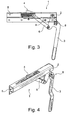
- the clamping element 4 is first withdrawn via the connecting element 6 in the guide 5 at the opening pivoting of the actuating lever 3 (see. FIGS. 3 and 4 ), in order then to further open the pivoting of the operating lever 3 according to the FIGS.
- the setting of the stop 14 takes place via a corresponding, designed in the illustrated embodiment as a crank 13 actuating element.
- the provided on the Endallonswagen 10 abutment 11 a displaceable in its position and be suitably assigned in a preselected position adjustable trained stop 14, which is provided on the vehicle side and not on the end run carriage 10.
- Fig. 8 for a precise adjustment of the clamping device 1 to the required clamping force or the required clamping travel of the clamping element 4, the clamping element 4 against the restoring force of a spring 12 formed as a spiral spring return element, in particular compression spring element, provided in the guide 5 and connected to the connecting element 6, so that an automatic adjustment is given.
- a spring 12 formed as a spiral spring return element, in particular compression spring element
Landscapes
- Engineering & Computer Science (AREA)
- Mechanical Engineering (AREA)
- Fittings On The Vehicle Exterior For Carrying Loads, And Devices For Holding Or Mounting Articles (AREA)
- Electrical Discharge Machining, Electrochemical Machining, And Combined Machining (AREA)
- Power-Operated Mechanisms For Wings (AREA)
- Forklifts And Lifting Vehicles (AREA)
- Seats For Vehicles (AREA)
Abstract
Description
Die Erfindung betrifft ein Spanneinrichtung für ein entlang von Lauf- und Führungsschiene verschiebliches Schiebeverdeck, wobei die Spanneinrichtung im Bereich der Lauf-und Führungsschiene vorgesehen ist und einen um eine Achse verschwenkbar angeordneten und zwischen einer Verriegelungsposition und einer Freigabeposition verlagerbaren Betätigungshebel sowie ein mit einem an dem Endlaufwagen vorgesehenen Gegenlager zusammenwirkendes und den Endlaufwagen zum Ende der Lauf- und Führungsschiene bewegendes, durch den Betätigungshebel in seiner Position veränderbares Spannelement aufweist.The invention relates to a clamping device for a sliding along sliding and guide rail sliding roof, wherein the clamping device is provided in the region of the running and guide rail and pivotable about an axis arranged and displaceable between a locking position and a release position actuating lever and a with a on the Endlaufwagen provided counter bearing cooperating and the Endlaufwagen to the end of the running and guide rail moving, by the operating lever in its position variable clamping element.
Aus der Praxis sind Spanneinrichtungen in verschiedensten Ausführungen bekannt, die im Laderaum angeordnet sind. Hierdurch ist sowohl die Betätigung mühsam und je nach Ausführung, beispielsweise durch langwierige Betätigung einer Kurbel, auch recht zeitaufwändig, und die Ladefläche wird verringert. Außerdem kann es zu Beschädigungen des Spannsystem durch die Ladung oder beim Be- und Entladen kommen.From practice clamping devices in various designs are known, which are arranged in the load compartment. As a result, both the operation is cumbersome and depending on the design, for example by tedious operation of a crank, also quite time consuming, and the loading area is reduced. In addition, it may cause damage to the clamping system by the load or loading and unloading.
Aufgabe der Erfindung ist es, die vorgenannten Nachteile zu vermeiden und ein Spannsystem anzugeben, das einfach bedienbar ist.The object of the invention is to avoid the aforementioned disadvantages and to provide a clamping system that is easy to use.
Diese Aufgabe wird dadurch gelöst, dass das Spannelement in einer entsprechend dem Verlauf der Lauf- und Führungsschiene ausgerichteten Führung angeordnet und über ein sowohl an dem Spannelement als auch an dem Betätigungshebel jeweils gelenkig angeschlagenes Verbindungselement in seiner Führung in Längsrichtung zwischen einer den Endlaufwagen am Ende der Lauf- und Führungsschiene haltenden Verriegelungsposition und einer Freigabeposition verlagerbar ist, wobei die Führung in einem Teilbereich unterseitig einen solchen Freiraum aufweist, dass das Spannelement bei Verlagerung des Betätigungshebels in die Freigabeposition zumindest teilweise soweit absenkbar ist, dass der Endlaufwagen von dem Ende der Lauf- und Führungsschiene weg verschoben werden kann. Hierdurch wird kein Platz im Laderaum beansprucht, da die Spanneinrichtung außerhalb, insbesondere unterhalb der Ladefläche, vorgesehen ist.This object is achieved in that the clamping element arranged in a correspondingly aligned to the course of the running and guide rail guide and a both on the clamping element and on the actuating lever hinged each connection element in its longitudinal guidance between a Endlaufwagen at the end of Run-and guide rail holding locking position and a release position is displaced, wherein the guide has in a sub-area at the bottom such a clearance that the clamping element at displacement of the actuating lever in the release position is at least partially lowered to the end of the end of the running and Guide rail can be moved away. As a result, no space in the cargo space is claimed, since the clamping device is provided outside, in particular below the loading area.
Dabei kann das Spannelement beim Absenken auch zusätzlich verkippbar sein, wodurch eine teilweise Absenkung resultiert und der erhöhte Bereich des Spannelementes, der mit dem Gegenlager zusammenwirkt, soweit abgesenkt wird, dass das Gegenlager über das Spannelement hinweg bewegbar ist.In this case, the clamping element during lowering can also be tilted, whereby a partial lowering results and the raised portion of the clamping element, which cooperates with the counter-bearing, is lowered so far that the counter-bearing over the clamping element is movable away.
Vorzugsweise kann die Anlenkung des Verbindungselements an dem Betätigungshebel derart vorgesehen sein, dass diese bei Verlagerung des Betätigungshebels in die Verriegelungsposition über einen Totpunkt hinweg erfolgt, so dass eine automatische Verriegelung erfolgt und ein Lösen ohne Krafteinwirkung nicht erfolgen kann.Preferably, the articulation of the connecting element may be provided on the actuating lever such that it takes place upon displacement of the actuating lever in the locking position over a dead center, so that an automatic locking takes place and a release without force can not be done.
Erfindungsgemäß kann das Spannelement über ein Druckfederelement, das bei in seiner Verriegelungsposition befindlichem Betätigungshebel eine geringe Verlagerung innerhalb der Führung ermöglicht, mit dem Verbindungselement verbunden sein, so dass eine Anpassung an Veränderungen der Lage des Gegenlagers innerhalb gewisser Grenzen möglich ist.According to the invention, the tensioning element can be connected to the connecting element via a compression spring element, which allows a slight displacement within the guide when the actuating lever is in its locking position, so that an adaptation to changes in the position of the anvil is possible within certain limits.
Bei einem bevorzugten Ausführungsbeispiel der Erfindung kann dem Betätigungshebel ein Verriegelungselement zur Arretierung in seiner Verriegelungsposition zugeordnet sein, so dass eine nochmals verbesserte Sicherung gegen versehentliches Lösen der Verriegelung durch das Spannelement gegeben ist.In a preferred embodiment of the invention, the actuating lever may be assigned a locking element for locking in its locking position, so that a further improved security against accidental release of the lock is given by the clamping element.
Vorteilhafterweise kann das Verriegelungselement am Betätigungshebel angeordnet sein und mit einer entsprechenden Aussparung in der Spanneinrichtung zusammenwirkend ausgebildet sein.Advantageously, the locking element can be arranged on the actuating lever and designed to cooperate with a corresponding recess in the clamping device.
Bei einem bevorzugten Ausführungsbeispiel der Erfindung kann der Betätigungshebel, insbesondere gegen eine Rückstellkraft, ausziehbar ausgebildet sein, so dass eine Verlängerung des Hebelarms für eine leichtere Betätigung möglich ist und die Baugröße bei Nichtbenutzung reduziert ist.In a preferred embodiment of the invention, the actuating lever, in particular against a restoring force, be designed extensible, so that an extension of the lever arm for easier operation is possible and the size is reduced when not in use.
Hierfür kann auch ein Verlängerungselement aus dem Betätigungshebel, insbesondere gegen eine Rückstellkraft, ausklappbar sein.For this purpose, an extension element from the actuating lever, in particular against a restoring force, be folded out.
Zur genauen Anpassung kann das an dem Endlaufwagen vorgesehene Gegenlager in seiner Position verlagerbar und entsprechend in einer vorgewählten Position einstellbar ausgebildet sein, so dass eine zu große Spannkraft verringerbar bzw. eine nicht ausreichende Spannkraft vergrößerbar ist.For exact adjustment provided on the end runner abutment can be displaced in its position and accordingly designed to be adjustable in a preselected position, so that an excessive clamping force can be reduced or an insufficient clamping force can be increased.
Auch kann das Spannelement hierfür gegen eine Rückstellkraft verlagerbar in der Führung vorgesehen und mit dem Verbindungselement verbunden sein.Also, the clamping element for this purpose can be provided displaceable in the guide against a restoring force and connected to the connecting element.
Im Folgenden wird ein in der Zeichnung dargestelltes Ausführungsbeispiel der Erfindung erläutert. Es zeigen:
- Fig. 1
- ein erstes Ausführungsbeispiel einer erfindungsgemäßen Spanneinrichtung in ge- schlossenem Zustand in einer seitlichen An- sicht,
- Fig. 2
- den Gegenstand nach
Fig. 1 in einer perspekti- vischen Ansicht von schräg oben, - Fig. 3
- den Gegenstand nach
Fig. 1 in halb geöffnetem Zustand, - Fig. 4
- den Gegenstand nach
Fig. 3 in einer perspekti- vischen Ansicht von schräg oben, - Fig. 5
- den Gegenstand nach
Fig. 1 in geöffnetem Zu- stand, - Fig. 6
- den Gegenstand nach
Fig. 5 in einer perspekti- vischen Ansicht von schräg oben, - Fig. 7
- eine Detailansicht eines zweiten Ausführungsbeispiels einer erfindungsgemäßen Spanneinrichtung, und
- Fig. 8
- eine Detailansicht eines dritten Ausführungsbeispiels einer erfindungsgemäßen Spanneinrichtung.
- Fig. 1
- a first embodiment of a clamping device according to the invention in the closed state in a lateral view,
- Fig. 2
- the object after
Fig. 1 in a perspective view obliquely from above, - Fig. 3
- the object after
Fig. 1 in half open condition, - Fig. 4
- the object after
Fig. 3 in a perspective view obliquely from above, - Fig. 5
- the object after
Fig. 1 in an open state, - Fig. 6
- the object after
Fig. 5 in a perspective view obliquely from above, - Fig. 7
- a detailed view of a second embodiment of a clamping device according to the invention, and
- Fig. 8
- a detailed view of a third embodiment of a clamping device according to the invention.
In allen Figuren werden für gleiche bzw. gleichartige Bauteile übereinstimmende Bezugszeichen verwendet.In all figures the same reference numerals are used for identical or similar components.
Die Figuren zeigen eine Spanneinrichtung 1 für ein entlang von Lauf- und Führungsschienen 15 verschiebliches, in der Zeichnung nicht dargestelltes Schiebeverdeck, wobei die Spanneinrichtung 1 im Bereich der Lauf- und Führungsschiene vorgesehen ist und einen um eine Achse 2 verschwenkbar angeordneten und zwischen einer Verriegelungsposition (
Dabei ist das Spannelement 4 in einer entsprechend dem Verlauf der Lauf- und Führungsschiene 15 ausgerichteten Führung 5 angeordnet und über ein sowohl an dem Spannelement 4 als auch an dem Betätigungshebel 3 jeweils gelenkig angeschlagenes Verbindungselement 6 in seiner Führung 5 in Längsrichtung zwischen einer den in der Zeichnung nicht dargestellten Endlaufwagen 10 am Ende der Lauf-und Führungsschiene haltenden Verriegelungsposition (
Die Führung 5 weist in einem Teilbereich unterseitig einen solchen Freiraum 7 auf, dass das Spannelement 4 bei Verlagerung des Betätigungshebels 3 in die Freigabeposition zumindest teilweise soweit absenkbar ist, dass der in der Zeichnung nicht dargestellte Endlaufwagen 10 von dem Ende der Lauf- und Führungsschiene 15 weg verschoben werden kann.The
Dem Betätigungshebel 3 ist ein Verriegelungselement 8 zur Arretierung in seiner Verriegelungsposition zugeordnet, das am Betätigungshebel 3 angeordnet ist und mit einer entsprechenden Aussparung 9 in der Spanneinrichtung 1 zusammenwirkend ausgebildet ist. Somit wird zunächst bei öffnendem Verschwenken des Betätigungshebels 3 das Spannelement 4 über das Verbindungselement 6 in der Führung 5 zurückgezogen (vgl.
Für eine genaue Anpassung der Spanneinrichtung 1 an die erforderliche Spannkraft bzw. den erforderlichen Spannweg des Spannelements 4 weist das an dem Endlaufwagen 10 vorgesehene Gegenlager 11 - wie in
Alternativ kann auch dem an dem Endlaufwagen 10 vorgesehenen Gegenlager 11 ein in seiner Position verlagerbarer und entsprechend in einer vorgewählten Position einstellbar ausgebildeter Anschlag 14 zugeordnet sein, der Fahrzeugseitig und nicht an dem Endlaufwagen 10 vorgesehen ist.Alternatively, the provided on the
Gemäß
Claims (8)
Priority Applications (10)
| Application Number | Priority Date | Filing Date | Title |
|---|---|---|---|
| EP09011299A EP2292456B1 (en) | 2009-09-03 | 2009-09-03 | Clamping device |
| SI200930204T SI2292456T1 (en) | 2009-09-03 | 2009-09-03 | Clamping device |
| AT09011299T ATE537988T1 (en) | 2009-09-03 | 2009-09-03 | CLAMPING DEVICE |
| PT09011299T PT2292456E (en) | 2009-09-03 | 2009-09-03 | Clamping device |
| ES09011299T ES2376299T3 (en) | 2009-09-03 | 2009-09-03 | SUBJECTION DEVICE. |
| DK09011299.6T DK2292456T3 (en) | 2009-09-03 | 2009-09-03 | Clamping device |
| PL09011299T PL2292456T3 (en) | 2009-09-03 | 2009-09-03 | Clamping device |
| US12/872,360 US8469436B2 (en) | 2009-09-03 | 2010-08-31 | Clamping device |
| HK11102988.7A HK1148715A1 (en) | 2009-09-03 | 2011-03-24 | Clamping device |
| HR20120038T HRP20120038T1 (en) | 2009-09-03 | 2012-01-12 | Clamping device |
Applications Claiming Priority (1)
| Application Number | Priority Date | Filing Date | Title |
|---|---|---|---|
| EP09011299A EP2292456B1 (en) | 2009-09-03 | 2009-09-03 | Clamping device |
Publications (2)
| Publication Number | Publication Date |
|---|---|
| EP2292456A1 true EP2292456A1 (en) | 2011-03-09 |
| EP2292456B1 EP2292456B1 (en) | 2011-12-21 |
Family
ID=41727489
Family Applications (1)
| Application Number | Title | Priority Date | Filing Date |
|---|---|---|---|
| EP09011299A Not-in-force EP2292456B1 (en) | 2009-09-03 | 2009-09-03 | Clamping device |
Country Status (10)
| Country | Link |
|---|---|
| US (1) | US8469436B2 (en) |
| EP (1) | EP2292456B1 (en) |
| AT (1) | ATE537988T1 (en) |
| DK (1) | DK2292456T3 (en) |
| ES (1) | ES2376299T3 (en) |
| HK (1) | HK1148715A1 (en) |
| HR (1) | HRP20120038T1 (en) |
| PL (1) | PL2292456T3 (en) |
| PT (1) | PT2292456E (en) |
| SI (1) | SI2292456T1 (en) |
Families Citing this family (2)
| Publication number | Priority date | Publication date | Assignee | Title |
|---|---|---|---|---|
| WO2013119614A1 (en) * | 2012-02-07 | 2013-08-15 | Southco, Inc. | Lever actuated compression latch |
| US20130257065A1 (en) * | 2012-03-29 | 2013-10-03 | B/E Aerospace, Inc. | Cart bay door paddle latch |
Citations (3)
| Publication number | Priority date | Publication date | Assignee | Title |
|---|---|---|---|---|
| JPS5467424U (en) * | 1977-10-21 | 1979-05-14 | ||
| US4943110A (en) * | 1987-05-21 | 1990-07-24 | The Eastern Company | Curtainside truck trailer access system and lock assembly |
| US20090072576A1 (en) * | 2007-03-02 | 2009-03-19 | Leblanc Sheri | Tarp enclosure system |
Family Cites Families (5)
| Publication number | Priority date | Publication date | Assignee | Title |
|---|---|---|---|---|
| US2961262A (en) * | 1959-05-25 | 1960-11-22 | John P Nockels | Latch mechanism |
| US3534992A (en) * | 1965-10-22 | 1970-10-20 | Nielsen Hardware Corp | Low profile catch for a packing case or the like |
| US5984382A (en) * | 1998-03-13 | 1999-11-16 | Hartwell Corporation | Extended reach latch |
| US6905161B2 (en) * | 1998-09-01 | 2005-06-14 | Edscha Lkw-Schiebeverdecke Gmbh | Sliding-bow folding up |
| US6343815B1 (en) * | 2000-10-04 | 2002-02-05 | Hartwell Corporation | Cinch-up latch |
-
2009
- 2009-09-03 SI SI200930204T patent/SI2292456T1/en unknown
- 2009-09-03 DK DK09011299.6T patent/DK2292456T3/en active
- 2009-09-03 EP EP09011299A patent/EP2292456B1/en not_active Not-in-force
- 2009-09-03 PT PT09011299T patent/PT2292456E/en unknown
- 2009-09-03 AT AT09011299T patent/ATE537988T1/en active
- 2009-09-03 PL PL09011299T patent/PL2292456T3/en unknown
- 2009-09-03 ES ES09011299T patent/ES2376299T3/en active Active
-
2010
- 2010-08-31 US US12/872,360 patent/US8469436B2/en active Active
-
2011
- 2011-03-24 HK HK11102988.7A patent/HK1148715A1/en not_active IP Right Cessation
-
2012
- 2012-01-12 HR HR20120038T patent/HRP20120038T1/en unknown
Patent Citations (3)
| Publication number | Priority date | Publication date | Assignee | Title |
|---|---|---|---|---|
| JPS5467424U (en) * | 1977-10-21 | 1979-05-14 | ||
| US4943110A (en) * | 1987-05-21 | 1990-07-24 | The Eastern Company | Curtainside truck trailer access system and lock assembly |
| US20090072576A1 (en) * | 2007-03-02 | 2009-03-19 | Leblanc Sheri | Tarp enclosure system |
Also Published As
| Publication number | Publication date |
|---|---|
| US20110047760A1 (en) | 2011-03-03 |
| EP2292456B1 (en) | 2011-12-21 |
| SI2292456T1 (en) | 2012-04-30 |
| HK1148715A1 (en) | 2011-09-16 |
| DK2292456T3 (en) | 2012-04-02 |
| PL2292456T3 (en) | 2012-05-31 |
| ATE537988T1 (en) | 2012-01-15 |
| US8469436B2 (en) | 2013-06-25 |
| ES2376299T3 (en) | 2012-03-12 |
| PT2292456E (en) | 2012-03-06 |
| HRP20120038T1 (en) | 2012-02-29 |
Similar Documents
| Publication | Publication Date | Title |
|---|---|---|
| AT501468B1 (en) | Pivotable sliding door, especially for railway vehicles, has a roller lever for engaging into a guide rail on a door leaf and for moving on a curved track | |
| EP3549900B1 (en) | Pneumatic platform for motor vehicles | |
| EP3446905B1 (en) | Erectable vehicle roof | |
| EP2627537B1 (en) | Ramp having a side barrier | |
| EP2700553A1 (en) | Bridge with a tunnel-shaped enveloping bellows between two vehicles joined through an articulated connection | |
| AT515195B1 (en) | Mobile footboard | |
| EP2292456B1 (en) | Clamping device | |
| EP2397353A1 (en) | Roof awning for covers on HGV or HGV trailers | |
| EP1743791B1 (en) | Arrangement for fixing a stanchion in the area of the upper structure of a utility vehicle | |
| EP1897727B1 (en) | Soft top with a rear bow for a convertible | |
| EP1595737A2 (en) | Extensible ramp for public service vehicles | |
| EP2703259B1 (en) | Latching device for locking and unlocking the tiltable cabin of a utility vehicle | |
| WO2013020154A1 (en) | Transport container | |
| WO2019238470A1 (en) | Assembly for a cover of a vehicle roof, and vehicle roof for a motor vehicle | |
| EP2759430B1 (en) | Slidable top structure | |
| EP1848603B1 (en) | Hard top | |
| EP2574180B1 (en) | Transport means with a lifting platform and pushing element | |
| EP2468548A2 (en) | Adjustment device for a top bow for a foldable roof | |
| DE10343507B4 (en) | Swiveling transport locking pin for a clamping device | |
| DE10064475B4 (en) | Locking device for a vehicle seat adjuster | |
| DE102014208166A1 (en) | Sliding roof structure | |
| DE102004054160B4 (en) | Hood for a convertible vehicle | |
| DE10330929B4 (en) | Method for securing the cargo of a vehicle provided with a tail lift and a tail lift | |
| DE102017109780B3 (en) | Structure for the transport of goods | |
| DE102022105423A1 (en) | Raising and lowering arrangement for container locking and raising and lowering methods therewith |
Legal Events
| Date | Code | Title | Description |
|---|---|---|---|
| PUAI | Public reference made under article 153(3) epc to a published international application that has entered the european phase |
Free format text: ORIGINAL CODE: 0009012 |
|
| AK | Designated contracting states |
Kind code of ref document: A1 Designated state(s): AT BE BG CH CY CZ DE DK EE ES FI FR GB GR HR HU IE IS IT LI LT LU LV MC MK MT NL NO PL PT RO SE SI SK SM TR |
|
| AX | Request for extension of the european patent |
Extension state: AL BA RS |
|
| 17P | Request for examination filed |
Effective date: 20110325 |
|
| GRAP | Despatch of communication of intention to grant a patent |
Free format text: ORIGINAL CODE: EPIDOSNIGR1 |
|
| RIC1 | Information provided on ipc code assigned before grant |
Ipc: B60J 5/06 20060101AFI20110519BHEP |
|
| REG | Reference to a national code |
Ref country code: HK Ref legal event code: DE Ref document number: 1148715 Country of ref document: HK |
|
| GRAS | Grant fee paid |
Free format text: ORIGINAL CODE: EPIDOSNIGR3 |
|
| GRAA | (expected) grant |
Free format text: ORIGINAL CODE: 0009210 |
|
| AK | Designated contracting states |
Kind code of ref document: B1 Designated state(s): AT BE BG CH CY CZ DE DK EE ES FI FR GB GR HR HU IE IS IT LI LT LU LV MC MK MT NL NO PL PT RO SE SI SK SM TR |
|
| REG | Reference to a national code |
Ref country code: GB Ref legal event code: FG4D Free format text: NOT ENGLISH |
|
| REG | Reference to a national code |
Ref country code: CH Ref legal event code: EP |
|
| REG | Reference to a national code |
Ref country code: HR Ref legal event code: TUEP Ref document number: P20120038 Country of ref document: HR |
|
| REG | Reference to a national code |
Ref country code: AT Ref legal event code: REF Ref document number: 537988 Country of ref document: AT Kind code of ref document: T Effective date: 20120115 |
|
| REG | Reference to a national code |
Ref country code: RO Ref legal event code: EPE Ref country code: IE Ref legal event code: FG4D |
|
| REG | Reference to a national code |
Ref country code: NL Ref legal event code: T3 |
|
| REG | Reference to a national code |
Ref country code: DE Ref legal event code: R096 Ref document number: 502009002232 Country of ref document: DE Effective date: 20120216 |
|
| REG | Reference to a national code |
Ref country code: HR Ref legal event code: T1PR Ref document number: P20120038 Country of ref document: HR |
|
| REG | Reference to a national code |
Ref country code: SE Ref legal event code: TRGR Ref country code: PT Ref legal event code: SC4A Free format text: AVAILABILITY OF NATIONAL TRANSLATION Effective date: 20120224 |
|
| REG | Reference to a national code |
Ref country code: ES Ref legal event code: FG2A Ref document number: 2376299 Country of ref document: ES Kind code of ref document: T3 Effective date: 20120312 |
|
| REG | Reference to a national code |
Ref country code: DK Ref legal event code: T3 |
|
| REG | Reference to a national code |
Ref country code: SK Ref legal event code: T3 Ref document number: E 11001 Country of ref document: SK |
|
| REG | Reference to a national code |
Ref country code: NO Ref legal event code: T2 Effective date: 20111221 |
|
| REG | Reference to a national code |
Ref country code: GR Ref legal event code: EP Ref document number: 20120400156 Country of ref document: GR Effective date: 20120305 |
|
| REG | Reference to a national code |
Ref country code: HK Ref legal event code: GR Ref document number: 1148715 Country of ref document: HK |
|
| REG | Reference to a national code |
Ref country code: PL Ref legal event code: T3 |
|
| PG25 | Lapsed in a contracting state [announced via postgrant information from national office to epo] |
Ref country code: CY Free format text: LAPSE BECAUSE OF FAILURE TO SUBMIT A TRANSLATION OF THE DESCRIPTION OR TO PAY THE FEE WITHIN THE PRESCRIBED TIME-LIMIT Effective date: 20111221 |
|
| PG25 | Lapsed in a contracting state [announced via postgrant information from national office to epo] |
Ref country code: IS Free format text: LAPSE BECAUSE OF FAILURE TO SUBMIT A TRANSLATION OF THE DESCRIPTION OR TO PAY THE FEE WITHIN THE PRESCRIBED TIME-LIMIT Effective date: 20120421 Ref country code: EE Free format text: LAPSE BECAUSE OF FAILURE TO SUBMIT A TRANSLATION OF THE DESCRIPTION OR TO PAY THE FEE WITHIN THE PRESCRIBED TIME-LIMIT Effective date: 20111221 |
|
| REG | Reference to a national code |
Ref country code: HR Ref legal event code: ODRP Ref document number: P20120038 Country of ref document: HR Payment date: 20120827 Year of fee payment: 4 |
|
| REG | Reference to a national code |
Ref country code: HU Ref legal event code: AG4A Ref document number: E013745 Country of ref document: HU |
|
| PLBE | No opposition filed within time limit |
Free format text: ORIGINAL CODE: 0009261 |
|
| STAA | Information on the status of an ep patent application or granted ep patent |
Free format text: STATUS: NO OPPOSITION FILED WITHIN TIME LIMIT |
|
| PGFP | Annual fee paid to national office [announced via postgrant information from national office to epo] |
Ref country code: IE Payment date: 20120918 Year of fee payment: 4 Ref country code: NO Payment date: 20120920 Year of fee payment: 4 Ref country code: LU Payment date: 20120924 Year of fee payment: 4 |
|
| 26N | No opposition filed |
Effective date: 20120924 |
|
| PGFP | Annual fee paid to national office [announced via postgrant information from national office to epo] |
Ref country code: SI Payment date: 20120823 Year of fee payment: 4 Ref country code: SK Payment date: 20120828 Year of fee payment: 4 Ref country code: HR Payment date: 20120827 Year of fee payment: 4 Ref country code: BG Payment date: 20120924 Year of fee payment: 4 Ref country code: LV Payment date: 20120921 Year of fee payment: 4 |
|
| PGFP | Annual fee paid to national office [announced via postgrant information from national office to epo] |
Ref country code: HU Payment date: 20120828 Year of fee payment: 4 |
|
| REG | Reference to a national code |
Ref country code: DE Ref legal event code: R097 Ref document number: 502009002232 Country of ref document: DE Effective date: 20120924 |
|
| PG25 | Lapsed in a contracting state [announced via postgrant information from national office to epo] |
Ref country code: MC Free format text: LAPSE BECAUSE OF NON-PAYMENT OF DUE FEES Effective date: 20120930 |
|
| PGFP | Annual fee paid to national office [announced via postgrant information from national office to epo] |
Ref country code: CH Payment date: 20130923 Year of fee payment: 5 |
|
| PGFP | Annual fee paid to national office [announced via postgrant information from national office to epo] |
Ref country code: MT Payment date: 20121002 Year of fee payment: 4 |
|
| REG | Reference to a national code |
Ref country code: HR Ref legal event code: PBON Ref document number: P20120038 Country of ref document: HR Effective date: 20130903 |
|
| REG | Reference to a national code |
Ref country code: PT Ref legal event code: MM4A Free format text: LAPSE DUE TO NON-PAYMENT OF FEES Effective date: 20140303 |
|
| PG25 | Lapsed in a contracting state [announced via postgrant information from national office to epo] |
Ref country code: HR Free format text: LAPSE BECAUSE OF NON-PAYMENT OF DUE FEES Effective date: 20130903 |
|
| REG | Reference to a national code |
Ref country code: DK Ref legal event code: EBP Effective date: 20130930 |
|
| REG | Reference to a national code |
Ref country code: GR Ref legal event code: ML Ref document number: 20120400156 Country of ref document: GR Effective date: 20140403 |
|
| PG25 | Lapsed in a contracting state [announced via postgrant information from national office to epo] |
Ref country code: SM Free format text: LAPSE BECAUSE OF FAILURE TO SUBMIT A TRANSLATION OF THE DESCRIPTION OR TO PAY THE FEE WITHIN THE PRESCRIBED TIME-LIMIT Effective date: 20111221 Ref country code: LV Free format text: LAPSE BECAUSE OF NON-PAYMENT OF DUE FEES Effective date: 20130903 |
|
| REG | Reference to a national code |
Ref country code: SI Ref legal event code: KO00 Effective date: 20140429 |
|
| REG | Reference to a national code |
Ref country code: SK Ref legal event code: MM4A Ref document number: E 11001 Country of ref document: SK Effective date: 20130903 |
|
| PG25 | Lapsed in a contracting state [announced via postgrant information from national office to epo] |
Ref country code: PT Free format text: LAPSE BECAUSE OF NON-PAYMENT OF DUE FEES Effective date: 20140303 |
|
| REG | Reference to a national code |
Ref country code: IE Ref legal event code: MM4A |
|
| PG25 | Lapsed in a contracting state [announced via postgrant information from national office to epo] |
Ref country code: NO Free format text: LAPSE BECAUSE OF NON-PAYMENT OF DUE FEES Effective date: 20130930 Ref country code: IE Free format text: LAPSE BECAUSE OF NON-PAYMENT OF DUE FEES Effective date: 20130903 |
|
| PG25 | Lapsed in a contracting state [announced via postgrant information from national office to epo] |
Ref country code: SI Free format text: LAPSE BECAUSE OF NON-PAYMENT OF DUE FEES Effective date: 20130904 Ref country code: SK Free format text: LAPSE BECAUSE OF NON-PAYMENT OF DUE FEES Effective date: 20130903 Ref country code: BG Free format text: LAPSE BECAUSE OF NON-PAYMENT OF DUE FEES Effective date: 20140630 Ref country code: GR Free format text: LAPSE BECAUSE OF NON-PAYMENT OF DUE FEES Effective date: 20140403 |
|
| PGFP | Annual fee paid to national office [announced via postgrant information from national office to epo] |
Ref country code: PT Payment date: 20120224 Year of fee payment: 4 |
|
| PG25 | Lapsed in a contracting state [announced via postgrant information from national office to epo] |
Ref country code: BG Free format text: LAPSE BECAUSE OF NON-PAYMENT OF DUE FEES Effective date: 20130930 Ref country code: HU Free format text: LAPSE BECAUSE OF NON-PAYMENT OF DUE FEES Effective date: 20130904 |
|
| PG25 | Lapsed in a contracting state [announced via postgrant information from national office to epo] |
Ref country code: BG Free format text: LAPSE BECAUSE OF NON-PAYMENT OF DUE FEES Effective date: 20140930 Ref country code: DK Free format text: LAPSE BECAUSE OF NON-PAYMENT OF DUE FEES Effective date: 20130930 |
|
| PGFP | Annual fee paid to national office [announced via postgrant information from national office to epo] |
Ref country code: FI Payment date: 20140922 Year of fee payment: 6 Ref country code: LT Payment date: 20140822 Year of fee payment: 6 Ref country code: RO Payment date: 20140826 Year of fee payment: 6 |
|
| REG | Reference to a national code |
Ref country code: DE Ref legal event code: R082 Ref document number: 502009002232 Country of ref document: DE Representative=s name: BONNEKAMP & SPARING, DE |
|
| PGFP | Annual fee paid to national office [announced via postgrant information from national office to epo] |
Ref country code: ES Payment date: 20140923 Year of fee payment: 6 |
|
| REG | Reference to a national code |
Ref country code: DE Ref legal event code: R081 Ref document number: 502009002232 Country of ref document: DE Owner name: EUROPEAN TRAILER SYSTEMS GMBH, DE Free format text: FORMER OWNER: VBG GROUP TRUCK EQUIPMENT GMBH, 47807 KREFELD, DE Effective date: 20141110 Ref country code: DE Ref legal event code: R082 Ref document number: 502009002232 Country of ref document: DE Representative=s name: BONNEKAMP & SPARING, DE Effective date: 20141110 |
|
| REG | Reference to a national code |
Ref country code: CH Ref legal event code: PL |
|
| PG25 | Lapsed in a contracting state [announced via postgrant information from national office to epo] |
Ref country code: MT Free format text: LAPSE BECAUSE OF NON-PAYMENT OF DUE FEES Effective date: 20130930 |
|
| PG25 | Lapsed in a contracting state [announced via postgrant information from national office to epo] |
Ref country code: LI Free format text: LAPSE BECAUSE OF NON-PAYMENT OF DUE FEES Effective date: 20140930 Ref country code: MK Free format text: LAPSE BECAUSE OF FAILURE TO SUBMIT A TRANSLATION OF THE DESCRIPTION OR TO PAY THE FEE WITHIN THE PRESCRIBED TIME-LIMIT Effective date: 20111221 Ref country code: CH Free format text: LAPSE BECAUSE OF NON-PAYMENT OF DUE FEES Effective date: 20140930 Ref country code: LU Free format text: LAPSE BECAUSE OF NON-PAYMENT OF DUE FEES Effective date: 20130903 |
|
| REG | Reference to a national code |
Ref country code: LT Ref legal event code: MM4D Effective date: 20150903 |
|
| PG25 | Lapsed in a contracting state [announced via postgrant information from national office to epo] |
Ref country code: LT Free format text: LAPSE BECAUSE OF NON-PAYMENT OF DUE FEES Effective date: 20150903 |
|
| PG25 | Lapsed in a contracting state [announced via postgrant information from national office to epo] |
Ref country code: FI Free format text: LAPSE BECAUSE OF NON-PAYMENT OF DUE FEES Effective date: 20150903 Ref country code: RO Free format text: LAPSE BECAUSE OF NON-PAYMENT OF DUE FEES Effective date: 20150903 |
|
| REG | Reference to a national code |
Ref country code: FR Ref legal event code: PLFP Year of fee payment: 8 |
|
| PGFP | Annual fee paid to national office [announced via postgrant information from national office to epo] |
Ref country code: AT Payment date: 20160921 Year of fee payment: 8 Ref country code: SE Payment date: 20160920 Year of fee payment: 8 |
|
| REG | Reference to a national code |
Ref country code: ES Ref legal event code: FD2A Effective date: 20170227 |
|
| PG25 | Lapsed in a contracting state [announced via postgrant information from national office to epo] |
Ref country code: ES Free format text: LAPSE BECAUSE OF NON-PAYMENT OF DUE FEES Effective date: 20150904 |
|
| REG | Reference to a national code |
Ref country code: FR Ref legal event code: PLFP Year of fee payment: 9 |
|
| REG | Reference to a national code |
Ref country code: SE Ref legal event code: EUG |
|
| REG | Reference to a national code |
Ref country code: AT Ref legal event code: MM01 Ref document number: 537988 Country of ref document: AT Kind code of ref document: T Effective date: 20170903 |
|
| PG25 | Lapsed in a contracting state [announced via postgrant information from national office to epo] |
Ref country code: AT Free format text: LAPSE BECAUSE OF NON-PAYMENT OF DUE FEES Effective date: 20170903 |
|
| REG | Reference to a national code |
Ref country code: FR Ref legal event code: PLFP Year of fee payment: 10 |
|
| PG25 | Lapsed in a contracting state [announced via postgrant information from national office to epo] |
Ref country code: MT Free format text: LAPSE BECAUSE OF NON-PAYMENT OF DUE FEES Effective date: 20130903 |
|
| PGFP | Annual fee paid to national office [announced via postgrant information from national office to epo] |
Ref country code: GR Payment date: 20180919 Year of fee payment: 14 Ref country code: CZ Payment date: 20180831 Year of fee payment: 10 |
|
| PG25 | Lapsed in a contracting state [announced via postgrant information from national office to epo] |
Ref country code: SE Free format text: LAPSE BECAUSE OF NON-PAYMENT OF DUE FEES Effective date: 20170904 |
|
| PGFP | Annual fee paid to national office [announced via postgrant information from national office to epo] |
Ref country code: TR Payment date: 20190829 Year of fee payment: 11 |
|
| PG25 | Lapsed in a contracting state [announced via postgrant information from national office to epo] |
Ref country code: CZ Free format text: LAPSE BECAUSE OF NON-PAYMENT OF DUE FEES Effective date: 20190903 |
|
| GBPC | Gb: european patent ceased through non-payment of renewal fee |
Effective date: 20190903 |
|
| PG25 | Lapsed in a contracting state [announced via postgrant information from national office to epo] |
Ref country code: GB Free format text: LAPSE BECAUSE OF NON-PAYMENT OF DUE FEES Effective date: 20190903 |
|
| PGFP | Annual fee paid to national office [announced via postgrant information from national office to epo] |
Ref country code: FR Payment date: 20200914 Year of fee payment: 12 Ref country code: NL Payment date: 20200925 Year of fee payment: 12 |
|
| PGFP | Annual fee paid to national office [announced via postgrant information from national office to epo] |
Ref country code: IT Payment date: 20210922 Year of fee payment: 13 |
|
| PGFP | Annual fee paid to national office [announced via postgrant information from national office to epo] |
Ref country code: BE Payment date: 20210920 Year of fee payment: 13 Ref country code: PL Payment date: 20210827 Year of fee payment: 13 Ref country code: DE Payment date: 20210920 Year of fee payment: 13 |
|
| REG | Reference to a national code |
Ref country code: NL Ref legal event code: MM Effective date: 20211001 |
|
| PG25 | Lapsed in a contracting state [announced via postgrant information from national office to epo] |
Ref country code: TR Free format text: LAPSE BECAUSE OF NON-PAYMENT OF DUE FEES Effective date: 20200903 Ref country code: NL Free format text: LAPSE BECAUSE OF NON-PAYMENT OF DUE FEES Effective date: 20211001 |
|
| PG25 | Lapsed in a contracting state [announced via postgrant information from national office to epo] |
Ref country code: FR Free format text: LAPSE BECAUSE OF NON-PAYMENT OF DUE FEES Effective date: 20210930 |
|
| REG | Reference to a national code |
Ref country code: DE Ref legal event code: R119 Ref document number: 502009002232 Country of ref document: DE |
|
| REG | Reference to a national code |
Ref country code: BE Ref legal event code: MM Effective date: 20220930 |
|
| PG25 | Lapsed in a contracting state [announced via postgrant information from national office to epo] |
Ref country code: DE Free format text: LAPSE BECAUSE OF NON-PAYMENT OF DUE FEES Effective date: 20230401 |
|
| PG25 | Lapsed in a contracting state [announced via postgrant information from national office to epo] |
Ref country code: BE Free format text: LAPSE BECAUSE OF NON-PAYMENT OF DUE FEES Effective date: 20220930 |
|
| PG25 | Lapsed in a contracting state [announced via postgrant information from national office to epo] |
Ref country code: IT Free format text: LAPSE BECAUSE OF NON-PAYMENT OF DUE FEES Effective date: 20220903 |
|
| PG25 | Lapsed in a contracting state [announced via postgrant information from national office to epo] |
Ref country code: PL Free format text: LAPSE BECAUSE OF NON-PAYMENT OF DUE FEES Effective date: 20220903 |