EP2295714A2 - Subterranean well tool including a locking seal healing system - Google Patents
Subterranean well tool including a locking seal healing system Download PDFInfo
- Publication number
- EP2295714A2 EP2295714A2 EP10188866A EP10188866A EP2295714A2 EP 2295714 A2 EP2295714 A2 EP 2295714A2 EP 10188866 A EP10188866 A EP 10188866A EP 10188866 A EP10188866 A EP 10188866A EP 2295714 A2 EP2295714 A2 EP 2295714A2
- Authority
- EP
- European Patent Office
- Prior art keywords
- tool
- translating
- tandem
- elastomeric member
- well
- Prior art date
- Legal status (The legal status is an assumption and is not a legal conclusion. Google has not performed a legal analysis and makes no representation as to the accuracy of the status listed.)
- Withdrawn
Links
Images


Classifications
-
- E—FIXED CONSTRUCTIONS
- E21—EARTH DRILLING; MINING
- E21B—EARTH DRILLING, e.g. DEEP DRILLING; OBTAINING OIL, GAS, WATER, SOLUBLE OR MELTABLE MATERIALS OR A SLURRY OF MINERALS FROM WELLS
- E21B33/00—Sealing or packing boreholes or wells
- E21B33/10—Sealing or packing boreholes or wells in the borehole
- E21B33/12—Packers; Plugs
- E21B33/1208—Packers; Plugs characterised by the construction of the sealing or packing means
- E21B33/1216—Anti-extrusion means, e.g. means to prevent cold flow of rubber packing
-
- E—FIXED CONSTRUCTIONS
- E21—EARTH DRILLING; MINING
- E21B—EARTH DRILLING, e.g. DEEP DRILLING; OBTAINING OIL, GAS, WATER, SOLUBLE OR MELTABLE MATERIALS OR A SLURRY OF MINERALS FROM WELLS
- E21B23/00—Apparatus for displacing, setting, locking, releasing, or removing tools, packers or the like in the boreholes or wells
- E21B23/06—Apparatus for displacing, setting, locking, releasing, or removing tools, packers or the like in the boreholes or wells for setting packers
-
- E—FIXED CONSTRUCTIONS
- E21—EARTH DRILLING; MINING
- E21B—EARTH DRILLING, e.g. DEEP DRILLING; OBTAINING OIL, GAS, WATER, SOLUBLE OR MELTABLE MATERIALS OR A SLURRY OF MINERALS FROM WELLS
- E21B33/00—Sealing or packing boreholes or wells
- E21B33/10—Sealing or packing boreholes or wells in the borehole
- E21B33/12—Packers; Plugs
- E21B33/128—Packers; Plugs with a member expanded radially by axial pressure
- E21B33/1285—Packers; Plugs with a member expanded radially by axial pressure by fluid pressure
Definitions
- a permanent or retrievable well plug such as a packer, bridge plug, tubing hanger assembly, positive-sealing-plugs or the like, will include an elastomer member for sealing across an interior area in tubular member or other well bore tubular previously set within the well.
- the elastomer member of such devices is expandable from a retracted position during run-in through the casing or opens whole on a conduit member, such as tubing, wire line or electric line, and is activated to seal within the well bore or tubular member through expansion.
- the elastomeric member of the well plug may be a series of rubber-like solid seal elements which are squeezed or compressed into sealing engagement with the well tubular member by a compressive force generated or transmitted through the well tool.
- anelastic behavior through the elastomer may occur.
- the industry widely uses cement retainers as a response to this behavior.
- Some such well plugs require up to 16,000 lbs. of force, or more, directed through the device to impart a compressive stress in the elastomer which causes it to form the necessary hydraulic seal in the well.
- anelastic (time-dependent deformation) behavior which can be referred to as creep and stress-relaxation
- creep and stress-relaxation an anelastic (time-dependent deformation) behavior which can be referred to as creep and stress-relaxation
- creep and stress-relaxation an anelastic (time-dependent deformation) behavior which can be referred to as creep and stress-relaxation
- creep and stress-relaxation an anelastic (time-dependent deformation) behavior which can be referred to as creep and stress-relaxation
- the third stage of creep has an accelerating creep rate and terminates by failure of material at time for rupture.
- a subterranean well tool such as a packer, bridge plug, or the like, in which the tool has a sealing system generally includes an elastomeric seal means together with extrusion rings, barriers, or the like at each end of the seal element.
- These anti-extrusion elements are intended to prevent the elastomeric member from extruding out of original sealing position relative to a conduit, such as tubular member, during setting, as well as a result of exposure to extreme high temperatures and/or pressures, together with the effects of time, on the seal means.
- the anti-extrusion features become more significant for high expansion, high differential pressure plug systems.
- a well tool with a multi-stage remedial system may be used within a subterranean well and improves the durability of a subterranean well tool having an expanded elastomeric member, such as a packer, for use inside a tubular member (a first conduit string, such as a drill string, production or work over string, electric or wire line, or the like).
- the well tool with multi-stage remedial system has a plurality of mandrel members shiftable within the tubular member for anchoring and for setting the seal system.
- a floating tandem mounted annularly around the lower mandrel members has one end (upon shifting) proximate an end of the seal system and the floating tandem has an opening to ambient bottom-hole-pressure of the subterranean well.
- a locking tandem is interposed with the floating tandem and at least one of the lower mandrel members. The floating tandem and the locking tandem together assist in abating elastomeric member extrusion under high temperature, high pressure environments as well as other conditions lending to failure within the well
- the well tool with multi-stage remedial system 10 (referred to herein as “tool and remedial system 10") used with a well plug or inflatable 11 is shown in run-in position within a tubular member or a casing conduit string 12 having an interior wall (normally smooth) 14.
- the tool and remedial system 10 is run into the well 16 and connected at its upper most end on a setting tool adapter rod 18 of a setting tool 20 which includes adapter sleeve 22.
- the setting tool 20 is, in turn, carried into the well 16 on a well conduit (not shown) such as a conventional work string, a tubing string, wire line, electric cable, or the like.
- the axial direction of the well 16 may be vertical, horizontal, or oblique (and may also be arcuate).
- the embodiments discussed herein will perform in each of these directions/environments and the drawings are intended to reflect each and every of the aforementioned directions (although the drawings may appear to represent only the vertical).
- the tool and remedial system 10 generally has a rigid-through tandem 30 ( Fig. 4 ) running primarily through the center of the tool and remedial system 10, a floating tandem 60 ( Fig. 5 ) located near the lower end along the periphery of the rigid-through tandem 30, and a locking tandem 90 ( Fig. 6 ) located external to the rigid-through tandem 30 and internal to the floating tandem 60.
- the rigid-through tandem 30 supports (and includes upon deployment) an anchor assembly 40 and also supports a seal system 50.
- the anchor assembly 40, the seal system 50, and the floating tandem 60 are operative for applying an elastomeric member 52 across the interior of the tubular member 12, whilst the floating tandem 60 functions as a mechanical driver to continue (over time) to urge the elastomeric member 52 around the interior of the tubular member (against interior wall 14).
- the compressive force on the elastomeric member 52 causes a seal by forcing the elastomeric member 52 to span and engage the inner diameter (interior wall 14) of the tubular member 12.
- the locking tandem 90 is employed in the system because the compressive force mentioned in the preceding paragraph must be sufficiently maintained under a variety of conditions in order to continue to effectuate the seal over time and more particularly under extreme operating conditions. Further, it must be maintained in a multi-directional manner meaning that changes in differential pressures, temperatures, deformities, fluid invasions (in the tubular member 12) and/or forces originating, for example, from the up-hole side 16a of the system as well as other directions such as but not limited to downhole must be accommodated in the system.
- the locking tandem 90 functions to maintain the compressive force by preventing hindward motion or retreat of the floating tandem 60 (i.e. it maintains rigidity in the system). In the embodiment shown the locking tandem 90 accomplishes this function by wedging between the rigid-through tandem 30 and the floating tandem 60 and by allowing motion in only one direction (via ratcheting).
- the compressed energy therefore becomes trapped in the elastomeric member 52 as a seal engaged in the inner diameter (interior wall 14) of the tubular member 12 causing a continued seal/plug in the tubular member 12 (whereas the elastomeric member 52 prefers to be in its lowest state of energy and therefore tends toward anelastic deformation to relieve or reduce the trapped energy).
- the elastomeric member 52 will eventually creep or extrude through a gap (not shown) between upper and lower metallic anti-extrusion envelope systems 59a and 59b and the interior wall 14.
- the elastomeric member 52 without sufficiently maintained compression can fail due to stress relaxation in the region of extrusion. These events lead to failure in the system.
- the floating tandem 60 may be urged against the seal system 50 mechanically, using differential pressure, by spring, or by any other known urging means, either individually or in combination.
- the urging will come in the axial direction of the tubular member 12 from the down-hole side 16b of the interior of the tubular member 12 in the normal case.
- the setting tool 20 carries the tool and remedial system 10 at its lower end.
- the tool and remedial system 10 includes a series of aligned mandrels 32a, 32b, 32c all of which are initially engaged together in series.
- the setting tool 20 is secured to the mandrel 32a by means of lock pin 27 disposed through a bore in an adaptor bushing 24.
- a companion screw or pin 28 is placed laterally at the upper end of the adaptor bushing 24 within a bore for securing the adaptor bushing 24 to the setting tool adapter rod 18.
- the series of aligned mandrels 32a, 32b, 32c together extend through the anchor assembly 40, the seal system 50, the floating tandem 60, and the locking tandem 90, whilst the mandrels 32b and 32c form part of the rigid-through tandem 30 ( Fig. 4 ).
- the mandrel 32a and the mandrel member 32b connect via threading at 33a engaging between the lower end of mandrel 32a and the upper end of mandrel 32b.
- Mandrel member 32c is connected via threading at 33b between the lower end of the mandrel member 32b and the upper end of member mandrel 32c, and accordingly, is responsive to movements of such shifting mandrel members.
- the anchor assembly 40 includes at its upper most end a wedging backup lock ring 41 which houses a lock ring member 42. Externally the lock ring member 42 has a set of angularly profiled locking teeth 42a that lock with the locking teeth 41 a internal to wedging backup lock ring 41. Internally the lock ring member 62 has a series of ratcheting teeth 42b which are permitted to ride upon (when moved into position) companion ratcheting teeth 34 carried exteriorly around the mandrel member 32b.
- the anchor assembly 40 also includes a series of radially bi-directional slips 43 secured or banded around the mandrel member 32a by a plurality of gasket rings 44 (three shown in the embodiment of Fig. 1A ).
- Each of the bi-directional slips 43 have sharp wicker tips 45 thereon for grasping the interior wall 14 of the casing 12, as the tool and remedial system 10 is moved to anchoring position (represented in Fig 2 ).
- Each of the bi-directional slip(s) 43 have upper 46a and lower wedging faces 46b.
- the upper 46a and lower wedging faces 46b are provided for slideably mating engagement and movements outwardly (when moving from unanchored to anchored position) along companion profiled surfaces 47a and 47b of the respective wedging backup lock ring 41 and lower wedging cone 48.
- the lower wedging cone 48 is initially secured to the mandrel member 32a by sheer screws 49.
- the seal system 50 includes an elastomeric member 52 of a nature that is well known to those skilled in the art.
- the seal system 50 includes the elastomeric member 52 having upper and lower ends (tapered inward toward the distal ends) 54a and 54b.
- the upper and lower ends 54a and 54b each respectively receive a series of upper and lower inner metal backup members 56a and 56b which are respectively sandwiched between an upper outer metal backup member 58a and a lower outer backup member 58b.
- the series of upper metal backup members 56a together with the upper outer metal backup member 58a form an upper metallic anti-extrusion envelope system 59a.
- the series of lower metal backup members 56b together with the lower outer metal backup member 58b form a lower metallic anti-extrusion envelope system 59b, while differing ambient wellbore pressure conditions can exist both above and below the seal system 50.
- the mandrel members 32a and 32b are pulled in one direction, such as upwardly, and the anchoring assembly 40 is shifted outwardly such that sharp wicker tips 45 with bi-directional slips 43 grasp and bite into and anchor along the interior wall 14 of the casing 12 at the desired setting depth.
- the elastomeric member 52 is then caused to be contracted in length and radially expands outwardly to seal against the interior wall 14, and the upper and lower metal backup members 54a and 54b are positioned relative to the casing wall 14 as shown in Fig. 2 .
- the lower portion of the tool and remedial system 10 will be discussed including the rigid-through tandem 30 (lower portion) ( Fig. 4 ), the floating tandem 60 ( Fig. 5 ) and the locking tandem 90 ( Fig. 6 ).
- the mandrel member 32c is secured via threading 33b to the lower most end of the mandrel member 32b.
- At least one piston head and rod assembly 34a having a piston head 35a and an extended rod segment 36a are carried around the mandrel member 32c.
- the top of piston head 35b abuts the bottom of extended rod segment 36a.
- the top of piston head 35a abuts the bottom of mandrel member 32b.
- Bull nose 38 is connected at the lower end of mandrel member 32c.
- Each of the piston head and rod assemblies 34a and 34b include a respective series of piston head seals 39a and 39b which seal against, but are permitted to slide along, as hereinafter described, a smooth interior surface 61 of a translating cylinder 62.
- the translating cylinder 62 and hence the floating tandem 60 is initially secured to the mandrel member 32b by means of shear screw 63.
- the floating tandem 60 generally includes the translating cylinder 62 and the translating drivers 65 and 70.
- the translating cylinder 62 has an upper translating cylinder component 63, a lower translating cylinder component 64 and a cylinder end ring 71.
- Lodged between the upper and lower translating cylinder components 63 and 64 is the translating driver 65 having a set of static seals 66 sealing against the interior surface 61 of the translating cylinder 62.
- the translating driver 65 also contains piston rod seals 67 facing to the interior and sealing against the extended rod segment 36a.
- the translating driver 65 is secured to the upper and lower translating cylinder components 63 and 64, respectively, via threading engagements 68 and 69.
- the translating driver 70 Lodged between the lower translating cylinder component 64 and cylinder end ring 71 is a translating driver 70.
- the translating driver 70 has a set of static seals 72 sealing against the interior surface 61 of the translating cylinder 62.
- the translating driver 70 also contains piston rod seals 73 facing to the interior and sealing against the extended rod segment 36b.
- the translating driver 70 is secured to the lower translating cylinder component 64 and the cylinder end ring 71, respectively, via threading engagements 74 and 75.
- vacuum chambers 80a and 80b are created between the each of the piston heads 35a and 35b and respective translating drivers 65 and 70 (between translating cylinder 62 and respective extended rod segments 36a and 36b) as further described below.
- the floating tandem 60 urges against the seal system 50 and can move over time relative to the rigid tandem 30.
- the relative movement between the floating tandem 60 and the rigid tandem 30 may be defined as a stroke length SL.
- the stroke length SL may be represented by contrasting the change in position of floating tandem 60 relative to rigid tandem 30 between Fig. 2 (where the stroke translated from hydrostatic bore pressure has not yet initiated or achieved any noticeable length) and Fig. 3 .
- the potential length of the healing stroke (or take-up stroke distance) SL is variable in length depending upon the parameters of a given application, and the actual stroke length SL in a given application is time dependent upon seal extrusion and the like.
- the translating cylinder 62 further includes a ram surface 76 at its upper most end.
- the locking tandem 90 works in conjunction with the rigid-through tandem 30 and the floating tandem 60 to maintain the seal system 50.
- the locking tandem 90 generally includes a wedging lock ring 92 and a collet lock ring 95, whilst the collet lock ring 95 includes a collet finger 96 a flexible ligament portion 97 and an expanding lock ring segment 98.
- the wedging lock ring 92 has a conically profiled outer face 94 and wedging lock ring directional internal teeth 93.
- the collet finger 96 connects to the flexible ligament portion 97 which connects to the expanding lock ring segment 98.
- the expanding lock ring segment 98 has outwardly facing ratcheting teeth 99.
- the mandrel member 32b includes a length of directional external teeth 37. These directional external teeth 37 interact (ride-on and ratchet) with companion wedging lock ring directional internal teeth 93 (see Figs. 7 & 8 ). Also, the translating cylinder 62 includes directional internal teeth 79 on the interior of the translating cylinder 62. These directional internal teeth 79 interact (ride-on and ratchet) with companion outwardly facing ratcheting teeth 99 on the expanding lock ring segment 98. The directional external teeth 37 together with the wedging lock ring directional internal teeth 93 are for allowing ratcheting-type one direction (only) motion of the wedging lock ring 92 relative to mandrel member 32b.
- the impetus for this motion comes from the collet lock ring 95 (when collet finger 96 pushes on the lower end of wedging lock ring 92).
- the impetus for the motion of collet lock ring 95 comes from the ratcheting-type interaction of directional internal teeth 79 with companion outwardly facing teeth 99 as the floating tandem 60 (or cylinder 62) moves toward the elastomeric member 52.
- the conically profiled outer face 94 is profiled for thrusting of the wedging lock ring 92 into wedging-engagement along a companionly profiled interior wall 77 of the translating cylinder 62.
- the wedging lock ring 92 is wedged into the translating cylinder 62 by interface of the walls or surfaces 94 and 77, the hindward motion of the floating tandem 60 will be blocked by the locking tandem 90 whilst the advancing or forward motion of the floating tandem 60 may continue (note that the advancing motion of the floating tandem 60 is translated from pressure defined as ambient well bore pressure at the setting depth of the tool and remedial system 10, as further described below).
- the rigid tandem 30 has at its lower end the conventional bull nose 38.
- the top 38a of bull nose 38 will abut a lower face 70a on the translating driver 70 upon completion of the initial movement of the rigid tandem 30 relative to the floating tandem 60 to initially set the seal system 50 ( Fig. 2 ).
- the floating tandem 60 further includes communication port(s) 82 through the translating cylinder 62 immediately below the translating driver 65. Recall that after the rigid tandem 30 is pulled relative to the floating tandem 60, vacuum chambers 80a and 80b (or regions of relatively lower pressure) are created.
- the communication port(s) 82 permit ambient well bore pressure to act upon the bottom of translating driver 65 resulting in a differential pressure relative to vacuum chamber 80a to drive the floating tandem 60 toward the seal system 50.
- the well pressure also acts upon the lower face 70a on the translating driver 70 resulting in a differential pressure relative to vacuum chamber 80b to further drive the floating tandem 60 toward the seal system 50.
- mandrels 32a, 32b, and 32c may vary depending upon the respective embodiment, and/or the nature of the floating tandem 60 and metallic anti-extrusion envelope system 59b may vary (see Figs. 9-11 which represent an embodiment functionally similar to Figs. 1-3 as an example in this regard).
- the number of vacuum chambers 80a, 80b and translating drivers 70, 75 combinations may vary, whilst having more than one makes the system "multi-stage" for enhancing pressure in a low hydrostatic pressure condition.
- the setting tool 20 When it is desired to run and set the tool and remedial system 10 within the tubular member 12 of the subterranean well 16, the setting tool 20 is secured at the upper most end of the tool and remedial system 10, as shown in Fig 1A . Thereafter, the tool and remedial system 10 is introduced into the well 16 on the setting tool 20.
- the adapter rod 18 of the setting tool 20 is pulled upwardly relative to the stable adaptor sleeve 22.
- the adapter rod 18 pulls a slip cradle 19 which sets mandrel member 32a in motion while adaptor sleeve 22 remains stationary (holding back-up lock ring 41 stationary).
- Shear pin(s) 17 are for anti-rotation.
- Shear screws 49 hold the lower wedging cone 48 in place.
- Shear screws 49 may, for example, be set to shear at one thousand pounds of shear force.
- the lower wedging cone 48 carried on the mandrel member 32a will also travel upwardly such that the profiled surface 47b will move along the companion profiled lower wedging face 46b of the radially bi-directional slips 43 of the anchor assembly 40.
- the similarly designed upper profiled surface 47a will travel along the upper wedging face 46a, to move the radially bi-directional slips 43 from the position shown in Fig. 1A to the anchoring position shown in Fig. 2 .
- the pulling upon the adaptor rod 18 will also cause the mandrel member 32a, the mandrel member 32b and the mandrel member 32c to be carried upwardly. During such movement, the ram surface 76 of the translating cylinder 62 will eventually contact the surface of the lower outer backup member 58b.
- hydrostatic well pressure may act through the communication port(s) 82 on the bottom of translating driver 65 and upon the lower face 70a on the translating driver 70 (creating a region of relatively higher pressure or differential pressure across this mechanical drive system) such that the translating drivers 65 and 70 in tandem drive the translating cylinder 62 upwardly during the "healing" stroke (that will create a stroke length SL over time), e.g., to compensate for extrusion in the elastomer beyond one or both of the metallic anti-extrusion envelope systems 59a and 59b.
- the locking tandem 90 functions to maintain the compressive force by preventing hindward motion or retreat of the floating tandem 60 while allowing advancement of the floating tandem 60 (together with the locking tandem 90).
- the locking tandem 90 accomplishes this function by interposing and wedging between the rigid-through tandem 30 and the floating tandem 60 and by allowing motion in only one direction (via ratcheting).
- the collet finger 96 urges the wedging lock ring 92 disposed around mandrel member 32b to ratchet upwardly until conically profiled outer face 94 on the wedging lock ring 92 comes into companion engagement with the companionly profiled interior wall 77 interior of the translating cylinder 62.
- the wedging lock ring 92 is uni-directionally locked into position between the interior of the cylinder 62 and the exterior of the mandrel member 32b when the collet finger 96 becomes inter-engaged by means of outwardly facing ratcheting teeth 99 on expanding lock ring segment 98 being lockingly inter-engaged with directional internal teeth 79. This position is as shown in Figs. 2 , 3 and 8 .
- the stroke length or "take-up" distance SL is determined by the relative motion between the floating tandem 60 (which acts to compress the elastomeric member 52) and the rigid tandem 30.
- the stroke length SL is significant in that it can make-up for extrusion (also deformities, expansion, contraction or washing away of debris at the interior wall 14) of elastomer at upper and lower outer metal backup members 58a and 58b, and upper and lower inner metal backup members 56a and 56b to effectuate a continued effective seal of the elastomeric member 52.
- the stroke length SL will be greater than 0.5 inches and could be up to and beyond four feet. This creates a sealing relationship that can be maintained for greater than eight to twelve hours, eliminating the need for cementing within such timeframes while using expansion ratios up to and beyond 3.4 to one.
- the healing system as shown is operable by mere translation of hydrostatic pressure forces from a bore-hole using differential pressure but could be operable based upon, by way of example but not limited to, pressurized gas contained in cylinders, or a spring system (e.g. disc or coil, not shown). Accordingly, modifications are contemplated which can be made without departing from the spirit of the described invention.
Abstract
Description
- During the drilling, completion or work over of a subterranean well, it is frequently necessary to isolate one or more zones or sections of the well for various purposes. A permanent or retrievable well plug, such as a packer, bridge plug, tubing hanger assembly, positive-sealing-plugs or the like, will include an elastomer member for sealing across an interior area in tubular member or other well bore tubular previously set within the well. The elastomer member of such devices is expandable from a retracted position during run-in through the casing or opens whole on a conduit member, such as tubing, wire line or electric line, and is activated to seal within the well bore or tubular member through expansion.
- The elastomeric member of the well plug may be a series of rubber-like solid seal elements which are squeezed or compressed into sealing engagement with the well tubular member by a compressive force generated or transmitted through the well tool.
- After the compressive force has been applied for considerable time through such elastomer, anelastic behavior through the elastomer may occur. The industry widely uses cement retainers as a response to this behavior. Some such well plugs require up to 16,000 lbs. of force, or more, directed through the device to impart a compressive stress in the elastomer which causes it to form the necessary hydraulic seal in the well. During the application of such high compressive forces, such elastomers are less likely to remain static, but ooze and squeeze or otherwise result in an anelastic (time-dependent deformation) behavior which can be referred to as creep and stress-relaxation, whilst the third stage of creep has an accelerating creep rate and terminates by failure of material at time for rupture. The anelastic behavior of materials are amplified by conditions of increased temperature, changing temperature, increased pressure, saturation of water, water invading seal elements and/or invading gases.
- The ability to provide a mechanism to abate and reduce anelastic behavior and the oozing of the seals under pressure is called "healing" and a system or mechanism for abating such phenomenon is called a "healing system".
- A subterranean well tool, such as a packer, bridge plug, or the like, in which the tool has a sealing system generally includes an elastomeric seal means together with extrusion rings, barriers, or the like at each end of the seal element. These anti-extrusion elements are intended to prevent the elastomeric member from extruding out of original sealing position relative to a conduit, such as tubular member, during setting, as well as a result of exposure to extreme high temperatures and/or pressures, together with the effects of time, on the seal means. The anti-extrusion features become more significant for high expansion, high differential pressure plug systems.
- A well tool with a multi-stage remedial system may be used within a subterranean well and improves the durability of a subterranean well tool having an expanded elastomeric member, such as a packer, for use inside a tubular member (a first conduit string, such as a drill string, production or work over string, electric or wire line, or the like). The well tool with multi-stage remedial system has a plurality of mandrel members shiftable within the tubular member for anchoring and for setting the seal system. A floating tandem mounted annularly around the lower mandrel members has one end (upon shifting) proximate an end of the seal system and the floating tandem has an opening to ambient bottom-hole-pressure of the subterranean well. A locking tandem is interposed with the floating tandem and at least one of the lower mandrel members. The floating tandem and the locking tandem together assist in abating elastomeric member extrusion under high temperature, high pressure environments as well as other conditions lending to failure within the well.
-
-
Figs 1A ,1B , and1C together constitute an elongated cross sectional view of one embodiment of the tool and remedial system as it is run into the well. -
Fig. 2 is a view similar to the combinedFigs 1A ,1 B and 1C illustrating the tool and remedial system being set to anchor the tool and application of the seal system to a sealing position against the well conduit or tubular member (locking tandem not yet engaged). -
Fig. 3 is a view, similar toFig 2 , illustrating the tool and remedial system with the floating tandem and locking tandem activated in response to hydrostatic well pressure at the tool setting depth. -
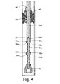
Fig. 4 is a sectional view of one embodiment of the rigid-through tandem 30. -
Fig. 5 is a sectional view of one embodiment of thefloating tandem 60. -
Fig. 6 is a sectional view of one embodiment of thelocking tandem 90. -
Fig. 7 is an area view fromFig. 1C of the area surrounding thelocking tandem 90. -
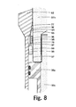
Fig. 8 is an area view fromFig. 3 of the area surrounding thelocking tandem 90. -
Fig. 9 constitutes a sectional view (below the seal system) of another embodiment of the tool and remedial system as it is run into the well (at a position similar toFigs. 1A ,1 B and 1 C ). -
Fig. 10 is a view similar toFig. 9 only showing the tool and remedial system being set for application of the seal system to a sealing position (at a position similar toFig. 2 ). -
Fig. 11 is a view similar toFigs. 9 and 10 illustrating the tool and remedial system with the floating tandem and locking tandem activated in response to hydrostatic well pressure at the tool setting depth (at a position similar toFig. 3 ). - Now referring to
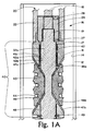
Figs 1A ,1B and1C , the well tool with multi-stage remedial system 10 (referred to herein as "tool andremedial system 10") used with a well plug or inflatable 11 is shown in run-in position within a tubular member or acasing conduit string 12 having an interior wall (normally smooth) 14. The tool andremedial system 10 is run into thewell 16 and connected at its upper most end on a settingtool adapter rod 18 of asetting tool 20 which includesadapter sleeve 22. Thesetting tool 20 is, in turn, carried into thewell 16 on a well conduit (not shown) such as a conventional work string, a tubing string, wire line, electric cable, or the like. - The axial direction of the
well 16 may be vertical, horizontal, or oblique (and may also be arcuate). The embodiments discussed herein will perform in each of these directions/environments and the drawings are intended to reflect each and every of the aforementioned directions (although the drawings may appear to represent only the vertical). - Referring to
Figs. 2-6 , the tool andremedial system 10 generally has a rigid-through tandem 30 (Fig. 4 ) running primarily through the center of the tool andremedial system 10, a floating tandem 60 (Fig. 5 ) located near the lower end along the periphery of the rigid-throughtandem 30, and a locking tandem 90 (Fig. 6 ) located external to the rigid-throughtandem 30 and internal to thefloating tandem 60. - Again generally but to be described in further detail below, the rigid-
through tandem 30 supports (and includes upon deployment) ananchor assembly 40 and also supports aseal system 50. Upon deployment, theanchor assembly 40, theseal system 50, and the floating tandem 60 (initially via mechanical force) are operative for applying anelastomeric member 52 across the interior of thetubular member 12, whilst thefloating tandem 60 functions as a mechanical driver to continue (over time) to urge theelastomeric member 52 around the interior of the tubular member (against interior wall 14). In other words the compressive force on theelastomeric member 52 causes a seal by forcing theelastomeric member 52 to span and engage the inner diameter (interior wall 14) of thetubular member 12. - The
locking tandem 90 is employed in the system because the compressive force mentioned in the preceding paragraph must be sufficiently maintained under a variety of conditions in order to continue to effectuate the seal over time and more particularly under extreme operating conditions. Further, it must be maintained in a multi-directional manner meaning that changes in differential pressures, temperatures, deformities, fluid invasions (in the tubular member 12) and/or forces originating, for example, from the up-hole side 16a of the system as well as other directions such as but not limited to downhole must be accommodated in the system. By way of example, a sufficient force from the up-hole side 16a could cause a momentary lapse, hindward motion or retreat in the floating tandem 60 (especially during anelastic behavior of the seals) such that the compressive force is momentarily released or slackened affording the opportunity for a change in the nature of the seal (see the following paragraph in this regard). Thelocking tandem 90 functions to maintain the compressive force by preventing hindward motion or retreat of the floating tandem 60 (i.e. it maintains rigidity in the system). In the embodiment shown thelocking tandem 90 accomplishes this function by wedging between the rigid-through tandem 30 and thefloating tandem 60 and by allowing motion in only one direction (via ratcheting). The compressed energy therefore becomes trapped in theelastomeric member 52 as a seal engaged in the inner diameter (interior wall 14) of thetubular member 12 causing a continued seal/plug in the tubular member 12 (whereas theelastomeric member 52 prefers to be in its lowest state of energy and therefore tends toward anelastic deformation to relieve or reduce the trapped energy). - Notably without maintaining the compressed energy in the
elastomeric member 52, theelastomeric member 52 will eventually creep or extrude through a gap (not shown) between upper and lower metallicanti-extrusion envelope systems interior wall 14. In addition, theelastomeric member 52 without sufficiently maintained compression can fail due to stress relaxation in the region of extrusion. These events lead to failure in the system. - It should be mentioned in passing at this juncture that the floating
tandem 60 may be urged against theseal system 50 mechanically, using differential pressure, by spring, or by any other known urging means, either individually or in combination. The urging will come in the axial direction of thetubular member 12 from the down-hole side 16b of the interior of thetubular member 12 in the normal case. - Now by way of greater detail in the embodiment shown by referring back to
Figs. 1A ,1B and1C , thesetting tool 20 carries the tool andremedial system 10 at its lower end. The tool andremedial system 10 includes a series of alignedmandrels setting tool 20 is secured to themandrel 32a by means oflock pin 27 disposed through a bore in an adaptor bushing 24. A companion screw orpin 28 is placed laterally at the upper end of the adaptor bushing 24 within a bore for securing the adaptor bushing 24 to the settingtool adapter rod 18. - In viewing
Figs 1A ,1B , and1C , it will be appreciated that the series of alignedmandrels anchor assembly 40, theseal system 50, thefloating tandem 60, and thelocking tandem 90, whilst themandrels Fig. 4 ). Themandrel 32a and themandrel member 32b connect via threading at 33a engaging between the lower end ofmandrel 32a and the upper end ofmandrel 32b. Mandrelmember 32c is connected via threading at 33b between the lower end of themandrel member 32b and the upper end ofmember mandrel 32c, and accordingly, is responsive to movements of such shifting mandrel members. - The
anchor assembly 40 includes at its upper most end a wedgingbackup lock ring 41 which houses alock ring member 42. Externally thelock ring member 42 has a set of angularly profiledlocking teeth 42a that lock with the locking teeth 41 a internal to wedgingbackup lock ring 41. Internally thelock ring member 62 has a series of ratchetingteeth 42b which are permitted to ride upon (when moved into position)companion ratcheting teeth 34 carried exteriorly around themandrel member 32b. - The
anchor assembly 40 also includes a series of radiallybi-directional slips 43 secured or banded around themandrel member 32a by a plurality of gasket rings 44 (three shown in the embodiment ofFig. 1A ). - Each of the
bi-directional slips 43 havesharp wicker tips 45 thereon for grasping theinterior wall 14 of thecasing 12, as the tool andremedial system 10 is moved to anchoring position (represented inFig 2 ). - Each of the bi-directional slip(s) 43 have upper 46a and lower wedging faces 46b. The upper 46a and lower wedging faces 46b are provided for slideably mating engagement and movements outwardly (when moving from unanchored to anchored position) along companion profiled surfaces 47a and 47b of the respective wedging
backup lock ring 41 andlower wedging cone 48. Thelower wedging cone 48 is initially secured to themandrel member 32a bysheer screws 49. - Now with reference to
Fig. 1 B , theseal system 50 will be discussed. As shown inFig. 1 B , themandrel member 32b is primarily disposed within the interior of theseal system 50 when the tool andremedial system 10 is in the run-in position. Theseal system 50 includes anelastomeric member 52 of a nature that is well known to those skilled in the art. In its broadest sense, theseal system 50 includes theelastomeric member 52 having upper and lower ends (tapered inward toward the distal ends) 54a and 54b. The upper andlower ends metal backup members metal backup member 58a and a lowerouter backup member 58b. When theseal system 50 is deployed (Fig. 2 ) the series of uppermetal backup members 56a together with the upper outermetal backup member 58a form an upper metallicanti-extrusion envelope system 59a. When theseal system 50 is deployed (Fig. 2 ) the series of lowermetal backup members 56b together with the lower outermetal backup member 58b form a lower metallicanti-extrusion envelope system 59b, while differing ambient wellbore pressure conditions can exist both above and below theseal system 50. - When the tool and
remedial system 10 is activated by manipulation of thesetting tool 20 themandrel members assembly 40 is shifted outwardly such thatsharp wicker tips 45 withbi-directional slips 43 grasp and bite into and anchor along theinterior wall 14 of thecasing 12 at the desired setting depth. Theelastomeric member 52 is then caused to be contracted in length and radially expands outwardly to seal against theinterior wall 14, and the upper and lowermetal backup members casing wall 14 as shown inFig. 2 . - Now with reference to
Fig 1C ,2 and3 , the lower portion of the tool andremedial system 10 will be discussed including the rigid-through tandem 30 (lower portion) (Fig. 4 ), the floating tandem 60 (Fig. 5 ) and the locking tandem 90 (Fig. 6 ). - As to rigid-through
tandem 30, themandrel member 32c is secured via threading 33b to the lower most end of themandrel member 32b. At least one piston head androd assembly 34a having apiston head 35a and anextended rod segment 36a are carried around themandrel member 32c. In the embodiment(s) shown, there is a second piston head androd assembly 34b including aspiston head 35b and anextended rod segment 36b carried around themandrel member 32c. The top ofpiston head 35b abuts the bottom ofextended rod segment 36a. The top ofpiston head 35a abuts the bottom ofmandrel member 32b.Bull nose 38 is connected at the lower end ofmandrel member 32c. The upper end ofbull nose 38 abuts the lower end ofextended rod segment 36b. When theanchor assembly 40 is anchored the various elements of the entire rigid-throughtandem 30 as represented inFig. 4 together become a unified rigid tandem of members, hence the term "rigid-through tandem" 30. - Each of the piston head and
rod assemblies interior surface 61 of a translatingcylinder 62. The translatingcylinder 62 and hence the floatingtandem 60 is initially secured to themandrel member 32b by means ofshear screw 63. - The floating
tandem 60 generally includes the translatingcylinder 62 and the translatingdrivers cylinder 62 has an upper translatingcylinder component 63, a lower translating cylinder component 64 and acylinder end ring 71. Lodged between the upper and lower translatingcylinder components 63 and 64 is the translatingdriver 65 having a set ofstatic seals 66 sealing against theinterior surface 61 of the translatingcylinder 62. The translatingdriver 65 also contains piston rod seals 67 facing to the interior and sealing against theextended rod segment 36a. The translatingdriver 65 is secured to the upper and lower translatingcylinder components 63 and 64, respectively, via threadingengagements - Lodged between the lower translating cylinder component 64 and
cylinder end ring 71 is a translatingdriver 70. The translatingdriver 70 has a set ofstatic seals 72 sealing against theinterior surface 61 of the translatingcylinder 62. The translatingdriver 70 also contains piston rod seals 73 facing to the interior and sealing against theextended rod segment 36b. The translatingdriver 70 is secured to the lower translating cylinder component 64 and thecylinder end ring 71, respectively, via threadingengagements - After the
rigid tandem 30 is pulled relative to the floatingtandem 60,vacuum chambers Fig. 2 , are created between the each of the piston heads 35a and 35b and respective translatingdrivers 65 and 70 (between translatingcylinder 62 and respectiveextended rod segments - After the
seal system 50 is set the floatingtandem 60 urges against theseal system 50 and can move over time relative to therigid tandem 30. The relative movement between the floatingtandem 60 and therigid tandem 30 may be defined as a stroke length SL. The stroke length SL may be represented by contrasting the change in position of floatingtandem 60 relative torigid tandem 30 betweenFig. 2 (where the stroke translated from hydrostatic bore pressure has not yet initiated or achieved any noticeable length) andFig. 3 . The potential length of the healing stroke (or take-up stroke distance) SL is variable in length depending upon the parameters of a given application, and the actual stroke length SL in a given application is time dependent upon seal extrusion and the like. - The translating
cylinder 62 further includes aram surface 76 at its upper most end. - When the translating
cylinder 62 is shifted upwardly by movement of themandrel member 32c in concert with adjoiningmandrel member 32b andmandrel member 32a as a result of shifting thesetting tool 20 in one direction, theram surface 76 of the translatingcylinder 62 will contact the lowerouter backup member 58b. Since theanchor assembly 40 of the tool andremedial system 10 previously has been moved outwardly into anchoring engagement with theinterior wall 14 of thetubular member 12, continued upper movement of the tool andremedial system 10 relative to themandrel members mandrel members elastomeric member 52 and the respective inner andouter backup members - When the
seal system 50 and theanchor assembly 40 are shifted toward the position as shown inFig 2 , continued pulling on thesetting tool 20 will cause themandrel members Fig. 1c but before the position shown inFig. 2 ) until the shear strength of the shear screw(s) 78 securing the translatingcylinder 62 to themandrel member 32b is overcome, and separates. - Referring more specifically to
Figs. 3 ,6 ,7 and8 , as briefly mentioned above the lockingtandem 90 works in conjunction with the rigid-throughtandem 30 and the floatingtandem 60 to maintain theseal system 50. The lockingtandem 90 generally includes a wedginglock ring 92 and acollet lock ring 95, whilst thecollet lock ring 95 includes a collet finger 96 aflexible ligament portion 97 and an expandinglock ring segment 98. - The wedging
lock ring 92 has a conically profiledouter face 94 and wedging lock ring directionalinternal teeth 93. Thecollet finger 96 connects to theflexible ligament portion 97 which connects to the expandinglock ring segment 98. The expandinglock ring segment 98 has outwardly facing ratchetingteeth 99. - The
mandrel member 32b includes a length of directionalexternal teeth 37. These directionalexternal teeth 37 interact (ride-on and ratchet) with companion wedging lock ring directional internal teeth 93 (seeFigs. 7 &8 ). Also, the translatingcylinder 62 includes directionalinternal teeth 79 on the interior of the translatingcylinder 62. These directionalinternal teeth 79 interact (ride-on and ratchet) with companion outwardly facing ratchetingteeth 99 on the expandinglock ring segment 98. The directionalexternal teeth 37 together with the wedging lock ring directionalinternal teeth 93 are for allowing ratcheting-type one direction (only) motion of the wedginglock ring 92 relative tomandrel member 32b. The impetus for this motion comes from the collet lock ring 95 (whencollet finger 96 pushes on the lower end of wedging lock ring 92). The impetus for the motion ofcollet lock ring 95 comes from the ratcheting-type interaction of directionalinternal teeth 79 with companion outwardly facingteeth 99 as the floating tandem 60 (or cylinder 62) moves toward theelastomeric member 52. - By comparing the position of the tool and
remedial system 10 shown inFig. 7 to Fig 8 , it will be realized that themandrel members Fig. 8 to initiate engagement between directionalinternal teeth 79 with companion outwardly facingteeth 99 and the "healing" movements of the tool andremedial system 10. Thereafter, during activation of the floatingtandem 60, ratchetingteeth 99 will ride on and ratchet along companionly profiled directionalinternal teeth 79. - The conically profiled
outer face 94 is profiled for thrusting of the wedginglock ring 92 into wedging-engagement along a companionly profiledinterior wall 77 of the translatingcylinder 62. When the wedginglock ring 92 is wedged into the translatingcylinder 62 by interface of the walls or surfaces 94 and 77, the hindward motion of the floatingtandem 60 will be blocked by the lockingtandem 90 whilst the advancing or forward motion of the floatingtandem 60 may continue (note that the advancing motion of the floatingtandem 60 is translated from pressure defined as ambient well bore pressure at the setting depth of the tool andremedial system 10, as further described below). - The
rigid tandem 30 has at its lower end theconventional bull nose 38. The top 38a ofbull nose 38 will abut a lower face 70a on the translatingdriver 70 upon completion of the initial movement of therigid tandem 30 relative to the floatingtandem 60 to initially set the seal system 50 (Fig. 2 ). - The floating
tandem 60 further includes communication port(s) 82 through the translatingcylinder 62 immediately below the translatingdriver 65. Recall that after therigid tandem 30 is pulled relative to the floatingtandem 60,vacuum chambers driver 65 resulting in a differential pressure relative to vacuumchamber 80a to drive the floatingtandem 60 toward theseal system 50. The well pressure also acts upon the lower face 70a on the translatingdriver 70 resulting in a differential pressure relative to vacuumchamber 80b to further drive the floatingtandem 60 toward theseal system 50. - The parts recited above are replaceable. For example, the number and nature of
mandrels tandem 60 and metallicanti-extrusion envelope system 59b may vary (seeFigs. 9-11 which represent an embodiment functionally similar toFigs. 1-3 as an example in this regard). The number ofvacuum chambers drivers - When it is desired to run and set the tool and
remedial system 10 within thetubular member 12 of thesubterranean well 16, thesetting tool 20 is secured at the upper most end of the tool andremedial system 10, as shown inFig 1A . Thereafter, the tool andremedial system 10 is introduced into the well 16 on thesetting tool 20. - At the desired location for setting of the tool and
remedial system 10, theadapter rod 18 of thesetting tool 20 is pulled upwardly relative to thestable adaptor sleeve 22. Theadapter rod 18 pulls aslip cradle 19 which setsmandrel member 32a in motion whileadaptor sleeve 22 remains stationary (holding back-uplock ring 41 stationary). Shear pin(s) 17 are for anti-rotation. - Multiple shear screws 49 hold the
lower wedging cone 48 in place. Shear screws 49 may, for example, be set to shear at one thousand pounds of shear force. As the settingstool adaptor rod 18 continues to be shifted or pulled upwardly, thelower wedging cone 48 carried on themandrel member 32a will also travel upwardly such that the profiledsurface 47b will move along the companion profiledlower wedging face 46b of the radiallybi-directional slips 43 of theanchor assembly 40. - Likewise, the similarly designed upper profiled surface 47a will travel along the
upper wedging face 46a, to move the radiallybi-directional slips 43 from the position shown inFig. 1A to the anchoring position shown inFig. 2 . - The pulling upon the
adaptor rod 18 will also cause themandrel member 32a, themandrel member 32b and themandrel member 32c to be carried upwardly. During such movement, theram surface 76 of the translatingcylinder 62 will eventually contact the surface of the lowerouter backup member 58b. - Continued upward pulling upon the setting tool adaptor of
rod 18 and themandrel members mandrel members anchor assembly 40. An upper face on the upper outermetal backup member 58a contacts thelower wedging cone 48, but because of the anchoring engagement of theanchor assembly 40, the stablelower wedging cone 48 and the upwardly moving translatingcylinder 62 will create compression and first cause theelastomeric member 52 to expand outwardly from the initial, run-in position shown inFig. 1 B , to set position shown inFig. 2 . Further travel of the translatingcylinder 62 in response to continued upward pulling on the settingtool adaptor rod 18 will compress and drive the upper and lower outermetal backup members metal backup members Fig. 2 where theelastomeric member 52 is driven against the inner diameter of the tubular member 12 (initially, for example, at 8,000 pounds force). This creates a condition where differing ambient wellbore pressure conditions can exist above and below theseal system 50. - Next, further upward pulling on the setting of
tool adaptor rod 18 is translated into the settingmandrel member tandem 60 is no longer pinned to therigid tandem 30. - Then, further upward movement of the rigid tandem 30 (by pulling) will create a void or
vacuum chambers drivers - When it is desired to remove the setting
tool adaptor rod 18 and themandrel member 32a out of the well, additional continued upward pulling upon theadaptor rod 18 will cause themandrel member 32a to shear frommandrel member 32b atweak point 36. Then theadopter rod 18 may be removed from the well with themandrel members 32a. - Now, because of the disengagement of the translating
cylinder member 62 from themandrel member 32c, hydrostatic well pressure may act through the communication port(s) 82 on the bottom of translatingdriver 65 and upon the lower face 70a on the translating driver 70 (creating a region of relatively higher pressure or differential pressure across this mechanical drive system) such that the translatingdrivers cylinder 62 upwardly during the "healing" stroke (that will create a stroke length SL over time), e.g., to compensate for extrusion in the elastomer beyond one or both of the metallicanti-extrusion envelope systems - The locking
tandem 90 functions to maintain the compressive force by preventing hindward motion or retreat of the floatingtandem 60 while allowing advancement of the floating tandem 60 (together with the locking tandem 90). In the embodiment shown, the lockingtandem 90 accomplishes this function by interposing and wedging between the rigid-throughtandem 30 and the floatingtandem 60 and by allowing motion in only one direction (via ratcheting). As the translatingcylinder 62 moves upwardly to further compress and exert pressure upon the upper and lower outermetal backup members metal backup members collet finger 96 urges the wedginglock ring 92 disposed aroundmandrel member 32b to ratchet upwardly until conically profiledouter face 94 on the wedginglock ring 92 comes into companion engagement with the companionly profiledinterior wall 77 interior of the translatingcylinder 62. The wedginglock ring 92 is uni-directionally locked into position between the interior of thecylinder 62 and the exterior of themandrel member 32b when thecollet finger 96 becomes inter-engaged by means of outwardly facing ratchetingteeth 99 on expandinglock ring segment 98 being lockingly inter-engaged with directionalinternal teeth 79. This position is as shown inFigs. 2 ,3 and8 . - The stroke length or "take-up" distance SL (see
Fig. 3 and compare and contrast toFig. 2 ) is determined by the relative motion between the floating tandem 60 (which acts to compress the elastomeric member 52) and therigid tandem 30. The stroke length SL is significant in that it can make-up for extrusion (also deformities, expansion, contraction or washing away of debris at the interior wall 14) of elastomer at upper and lower outermetal backup members metal backup members elastomeric member 52. In a preferred embodiment the stroke length SL will be greater than 0.5 inches and could be up to and beyond four feet. This creates a sealing relationship that can be maintained for greater than eight to twelve hours, eliminating the need for cementing within such timeframes while using expansion ratios up to and beyond 3.4 to one. - Although the invention has been described in terms of specified embodiments which are set forth in detail, it should be understood that this is by illustration only that the invention is not necessarily limited thereto, since alternative embodiments and operating techniques will become apparent to those skilled in the art in view of the disclosure. By way of example, the healing system as shown is operable by mere translation of hydrostatic pressure forces from a bore-hole using differential pressure but could be operable based upon, by way of example but not limited to, pressurized gas contained in cylinders, or a spring system (e.g. disc or coil, not shown).. Accordingly, modifications are contemplated which can be made without departing from the spirit of the described invention.
Claims (15)
- A system for compensating for anelastic behavior of an expanded seal means and multidirectional forces of a subterranean well tool , said seal means including an elastomeric sealing member and seal back-up members , said well tool being introduced into said well on a first conduit , said seal means being expandable from a retracted, run-in position, to a set position along a conduit member of a second conduit string, said healing system being activated subsequent to the expansion of said seal means to said set position, said seal healing system comprising:(a) a shiftable mandrel carried on said first conduit ;(b) translating cylinder means activatably moveable, from an initial position, in response to shifting of said mandrel, to a healing position, in response to hydrostatic pressure in said well:(c) means for selectively engaging said mandrel to said translating cylinder when said seal means is in the run-in and set positions;(d) means responsive to said hydrostatic pressure in said well subsequent to said seal means being shifted to said set position, to stroke the translating cylinder means toward and to the healing position; and(e) means for locking the translating cylinder means in the full, healing position.
- The system according to claim 1, wherein said means responsive to said hydrostatic pressure in said well subsequent to said seal means being shifted to said set position, to stroke the translating cylinder means toward and to the healing position is carried out over a stroke distance exceeding 0.5 inches.
- An apparatus for maintaining a compression force on an elastomeric member of a downhole tool, comprising:a piston head and a translating driver defining a chamber wherein the chamber defines a region of relatively low pressure; andwherein the piston head and the translating driver are moved apart upon setting the tool downhole.
- The apparatus according to claim 3, wherein a well pressure acts on the translating driver to urge it towards the piston head, thereby maintaining a compression force on the elastomeric member.
- The apparatus according to claim 4, wherein the elastomeric member of the downhole tool is radially expanded outwardly engaging a wall of a wellbore for setting the tool downhole.
- The apparatus according to claim 5, further comprising a means for preventing hindward motion interposed with the piston head and the translating driver.
- The apparatus according to claim 6, wherein said means for preventing hindward motion comprises a locking tandem.
- The apparatus according to claim 7, wherein said locking tandem comprises a wedging lock ring; and a collet lock ring mounted contiguous with said wedging lock ring.
- The apparatus according to claim 3, wherein the elastomeric member of the downhole tool is radially expanded outwardly engaging a wall of a wellbore for setting the tool downhole.
- The apparatus according to claim 9, further comprising a means for preventing hindward motion interposed with the piston head and the translating driver.
- The apparatus according to claim 10, wherein said means for preventing hindward motion comprises a locking tandem comprising a wedging lock ring; and a collet lock ring mounted contiguous with said wedging lock ring.
- A method including providing a tool having an elastomeric member, and running the tool into a wellbore, comprising the steps of:activating the elastomeric member into a set position while the tool is in the wellbore whereby the elastomeric member is engaging a wall of the wellbore; andcreating a region of relatively low pressure within a chamber defined by a piston head and a translating driver by moving one of the piston head and the translating driver away from the other while the tool is in the wellbore.
- The method according to claim 12, wherein well pressure within the wellbore is acting on the translating driver for urging the translating driver towards the piston head.
- The method according to claim 13, wherein said step of activating the elastomeric member into the set position while the tool is in the wellbore whereby the elastomeric member is engaging the wall of the wellbore further comprises:compressing the elastomeric member and expanding the elastomeric member radially for engaging the wall of the wellbore for setting the tool downhole.
- The method according to claim 14, wherein said step of compressing the elastomeric member and expanding the elastomeric member radially occurs prior to said step of moving one of the piston head and the translating driver away from the other.
Applications Claiming Priority (2)
| Application Number | Priority Date | Filing Date | Title |
|---|---|---|---|
| US11/679,302 US7779905B2 (en) | 2007-02-27 | 2007-02-27 | Subterranean well tool including a locking seal healing system |
| EP08250548A EP1965019B1 (en) | 2007-02-27 | 2008-02-16 | Subterranean well tool including a locking seal healing system |
Related Parent Applications (1)
| Application Number | Title | Priority Date | Filing Date |
|---|---|---|---|
| EP08250548.8 Division | 2008-02-16 |
Publications (2)
| Publication Number | Publication Date |
|---|---|
| EP2295714A2 true EP2295714A2 (en) | 2011-03-16 |
| EP2295714A3 EP2295714A3 (en) | 2011-06-01 |
Family
ID=39485165
Family Applications (3)
| Application Number | Title | Priority Date | Filing Date |
|---|---|---|---|
| EP08250548A Active EP1965019B1 (en) | 2007-02-27 | 2008-02-16 | Subterranean well tool including a locking seal healing system |
| EP10188866A Withdrawn EP2295714A3 (en) | 2007-02-27 | 2008-02-16 | Subterranean well tool including a locking seal healing system |
| EP10188862A Withdrawn EP2295713A1 (en) | 2007-02-27 | 2008-02-16 | Subterranean well tool including a locking seal healing system |
Family Applications Before (1)
| Application Number | Title | Priority Date | Filing Date |
|---|---|---|---|
| EP08250548A Active EP1965019B1 (en) | 2007-02-27 | 2008-02-16 | Subterranean well tool including a locking seal healing system |
Family Applications After (1)
| Application Number | Title | Priority Date | Filing Date |
|---|---|---|---|
| EP10188862A Withdrawn EP2295713A1 (en) | 2007-02-27 | 2008-02-16 | Subterranean well tool including a locking seal healing system |
Country Status (6)
| Country | Link |
|---|---|
| US (2) | US7779905B2 (en) |
| EP (3) | EP1965019B1 (en) |
| AT (1) | ATE486194T1 (en) |
| AU (2) | AU2008200696B2 (en) |
| CA (1) | CA2622052C (en) |
| DE (1) | DE602008003137D1 (en) |
Families Citing this family (19)
| Publication number | Priority date | Publication date | Assignee | Title |
|---|---|---|---|---|
| US7387170B2 (en) * | 2002-04-05 | 2008-06-17 | Baker Hughes Incorporated | Expandable packer with mounted exterior slips and seal |
| US8881836B2 (en) * | 2007-09-01 | 2014-11-11 | Weatherford/Lamb, Inc. | Packing element booster |
| US8459347B2 (en) * | 2008-12-10 | 2013-06-11 | Oiltool Engineering Services, Inc. | Subterranean well ultra-short slip and packing element system |
| NO332116B1 (en) | 2010-12-15 | 2012-06-25 | Btu Bronnteknologiutvikling As | Plug device |
| US8813841B2 (en) | 2010-12-22 | 2014-08-26 | James V. Carisella | Hybrid dump bailer and method of use |
| EP2678523A2 (en) | 2011-02-22 | 2014-01-01 | Weatherford/Lamb, Inc. | Subsea conductor anchor |
| US10323477B2 (en) * | 2012-10-15 | 2019-06-18 | Weatherford Technology Holdings, Llc | Seal assembly |
| WO2014178866A1 (en) * | 2013-05-02 | 2014-11-06 | Halliburton Energy Services, Inc. | Sealing annular gaps in a well |
| CN103591295B (en) * | 2013-11-21 | 2016-07-06 | 天津科技大学 | There is the movable sealing structure of bottom compression function |
| US9732566B2 (en) | 2013-11-22 | 2017-08-15 | Weatherford Technology Holdings, Llc | Downhole release tool |
| US20150144335A1 (en) * | 2013-11-25 | 2015-05-28 | Schlumberger Technology Corporation | Power retrieving tool |
| US9476272B2 (en) | 2014-12-11 | 2016-10-25 | Neo Products, LLC. | Pressure setting tool and method of use |
| US9803440B2 (en) | 2015-03-09 | 2017-10-31 | Halliburton Energy Services, Inc. | Setting a downhole tool in a wellbore |
| US10472922B2 (en) | 2015-09-21 | 2019-11-12 | Innovex Downhole Solutions, Inc. | Well plug anchor tool |
| US10337270B2 (en) | 2015-12-16 | 2019-07-02 | Neo Products, LLC | Select fire system and method of using same |
| US11131163B2 (en) * | 2017-10-06 | 2021-09-28 | G&H Diversified Manufacturing Lp | Systems and methods for sealing a wellbore |
| ES2905869T3 (en) | 2017-10-26 | 2022-04-12 | Non Explosive Oilfield Products Llc | Downhole positioning tool with fluid actuator and its use method |
| WO2019089198A1 (en) * | 2017-11-01 | 2019-05-09 | Geodynamics, Inc. | Device and method for retrieving a restriction element from a well |
| US10590732B2 (en) | 2017-12-19 | 2020-03-17 | Weatherford Technology Holdings, Llc | Packing element booster with ratchet mechanism |
Family Cites Families (36)
| Publication number | Priority date | Publication date | Assignee | Title |
|---|---|---|---|---|
| US2566323A (en) * | 1948-05-08 | 1951-09-04 | Lane Wells Co | Bridging plug setting tool |
| US2742968A (en) | 1952-12-11 | 1956-04-24 | Exxon Research Engineering Co | Self-inflating balloon type formation tester |
| US3011055A (en) | 1954-06-03 | 1961-11-28 | J J Maguire | Method and means for gauging fine strands |
| US3011555A (en) * | 1958-04-14 | 1961-12-05 | Baker Oil Tools Inc | Well packers |
| US3221818A (en) * | 1962-06-11 | 1965-12-07 | Otis Eng Co | Fluid pressure actuated well packer |
| US3339637A (en) | 1965-10-14 | 1967-09-05 | Halliburton Co | Well packers |
| US3459261A (en) * | 1965-12-13 | 1969-08-05 | Brown Oil Tools | Pressure differential expanding means for well packers |
| US3706342A (en) * | 1969-09-15 | 1972-12-19 | Brown J Woolley | Packer for wells |
| US3603390A (en) | 1969-09-15 | 1971-09-07 | Schlumberger Technology Corp | Fluid pressure-responsive well packer |
| US3587736A (en) * | 1970-04-09 | 1971-06-28 | Cicero C Brown | Hydraulic open hole well packer |
| US3702634A (en) * | 1970-06-10 | 1972-11-14 | Halliburton Co | Retrievable packer apparatus for use in a well bore and method of prolonging its operating life |
| US3872295A (en) * | 1973-02-27 | 1975-03-18 | William B Clancy | Apparatus for inspecting confined areas adjacent the floor |
| US4044826A (en) * | 1976-05-17 | 1977-08-30 | Baker International Corporation | Retrievable well packers |
| US4224987A (en) | 1978-02-13 | 1980-09-30 | Brown Oil Tools, Inc. | Well tool |
| US4518037A (en) * | 1981-12-10 | 1985-05-21 | Youngblood Harold C | Retrievable well tool |
| US4438933A (en) * | 1982-05-06 | 1984-03-27 | Halliburton Company | Hydraulic set high temperature isolation packer |
| US4554973A (en) * | 1983-10-24 | 1985-11-26 | Schlumberger Technology Corporation | Apparatus for sealing a well casing |
| US4924941A (en) * | 1989-10-30 | 1990-05-15 | Completion Services, Inc. | Bi-directional pressure assisted sealing packers |
| US5010958A (en) * | 1990-06-05 | 1991-04-30 | Schlumberger Technology Corporation | Multiple cup bridge plug for sealing a well casing and method |
| US5058673A (en) * | 1990-08-28 | 1991-10-22 | Schlumberger Technology Corporation | Hydraulically set packer useful with independently set straddle packers including an inflate/deflate valve and a hydraulic ratchet associated with the straddle packers |
| US5146983A (en) * | 1991-03-15 | 1992-09-15 | Schlumberger Technology Corporation | Hydrostatic setting tool including a selectively operable apparatus initially blocking an orifice disposed between two chambers and opening in response to a signal |
| US5560426A (en) * | 1995-03-27 | 1996-10-01 | Baker Hughes Incorporated | Downhole tool actuating mechanism |
| CA2182913C (en) | 1995-08-14 | 2006-04-04 | Morten Myhre | Pressure-boost device for downhole tools |
| US5819854A (en) * | 1996-02-06 | 1998-10-13 | Baker Hughes Incorporated | Activation of downhole tools |
| US5893413A (en) * | 1996-07-16 | 1999-04-13 | Baker Hughes Incorporated | Hydrostatic tool with electrically operated setting mechanism |
| US5810082A (en) | 1996-08-30 | 1998-09-22 | Baker Hughes Incorporated | Hydrostatically actuated packer |
| US6202748B1 (en) * | 1999-04-15 | 2001-03-20 | Weatherford International, Inc. | Multi-stage maintenance device for subterranean well tool |
| US6318461B1 (en) * | 1999-05-11 | 2001-11-20 | James V. Carisella | High expansion elastomeric plug |
| US6354372B1 (en) * | 2000-01-13 | 2002-03-12 | Carisella & Cook Ventures | Subterranean well tool and slip assembly |
| US6311778B1 (en) * | 2000-04-18 | 2001-11-06 | Carisella & Cook Ventures | Assembly and subterranean well tool and method of use |
| US6779600B2 (en) * | 2001-07-27 | 2004-08-24 | Baker Hughes Incorporated | Labyrinth lock seal for hydrostatically set packer |
| GB2392697B (en) | 2001-12-12 | 2006-07-12 | Weatherford Lamb | Bi-directional and internal pressure trapping packing element system |
| US6823945B2 (en) * | 2002-09-23 | 2004-11-30 | Schlumberger Technology Corp. | Pressure compensating apparatus and method for downhole tools |
| SE527426C2 (en) * | 2004-07-08 | 2006-02-28 | Atlas Copco Rocktech Ab | Device for attaching an expandable packer to a hole |
| US7552777B2 (en) | 2005-12-28 | 2009-06-30 | Baker Hughes Incorporated | Self-energized downhole tool |
| US7455118B2 (en) * | 2006-03-29 | 2008-11-25 | Smith International, Inc. | Secondary lock for a downhole tool |
-
2007
- 2007-02-27 US US11/679,302 patent/US7779905B2/en active Active
-
2008
- 2008-02-14 AU AU2008200696A patent/AU2008200696B2/en not_active Ceased
- 2008-02-16 AT AT08250548T patent/ATE486194T1/en not_active IP Right Cessation
- 2008-02-16 EP EP08250548A patent/EP1965019B1/en active Active
- 2008-02-16 DE DE602008003137T patent/DE602008003137D1/en active Active
- 2008-02-16 EP EP10188866A patent/EP2295714A3/en not_active Withdrawn
- 2008-02-16 EP EP10188862A patent/EP2295713A1/en not_active Withdrawn
- 2008-02-21 CA CA2622052A patent/CA2622052C/en not_active Expired - Fee Related
-
2010
- 2010-08-23 US US12/861,452 patent/US8191645B2/en active Active
-
2014
- 2014-07-17 AU AU2014204473A patent/AU2014204473B2/en not_active Ceased
Non-Patent Citations (1)
| Title |
|---|
| None |
Also Published As
| Publication number | Publication date |
|---|---|
| US8191645B2 (en) | 2012-06-05 |
| AU2008200696A1 (en) | 2008-09-11 |
| ATE486194T1 (en) | 2010-11-15 |
| US7779905B2 (en) | 2010-08-24 |
| AU2008200696B2 (en) | 2014-10-02 |
| EP2295713A1 (en) | 2011-03-16 |
| EP1965019A2 (en) | 2008-09-03 |
| CA2622052C (en) | 2014-12-16 |
| EP1965019B1 (en) | 2010-10-27 |
| EP2295714A3 (en) | 2011-06-01 |
| US20080202771A1 (en) | 2008-08-28 |
| DE602008003137D1 (en) | 2010-12-09 |
| EP1965019A3 (en) | 2009-02-18 |
| CA2622052A1 (en) | 2008-08-27 |
| AU2014204473A1 (en) | 2014-08-07 |
| US20100314135A1 (en) | 2010-12-16 |
| AU2014204473B2 (en) | 2016-04-28 |
Similar Documents
| Publication | Publication Date | Title |
|---|---|---|
| AU2014204473B2 (en) | Subterranean well tool including a locking seal healing system | |
| EP3728788B1 (en) | Packing element booster | |
| CA2582751C (en) | Secondary lock for a downhole tool | |
| CA2782819C (en) | Retrieval method for opposed slip type packers | |
| AU785197B2 (en) | Lock ring for pipe slip pick-up ring | |
| US9145755B2 (en) | Sealing annular gaps in a well | |
| US20050217869A1 (en) | High pressure expandable packer | |
| US9617823B2 (en) | Axially compressed and radially pressed seal | |
| AU2014312415B2 (en) | Packer having swellable and compressible elements | |
| CA2939070C (en) | Sealing element for downhole tool | |
| WO2017034671A1 (en) | Convertible plug seal assembly |
Legal Events
| Date | Code | Title | Description |
|---|---|---|---|
| PUAI | Public reference made under article 153(3) epc to a published international application that has entered the european phase |
Free format text: ORIGINAL CODE: 0009012 |
|
| AC | Divisional application: reference to earlier application |
Ref document number: 1965019 Country of ref document: EP Kind code of ref document: P |
|
| AK | Designated contracting states |
Kind code of ref document: A2 Designated state(s): AT BE BG CH CY CZ DE DK EE ES FI FR GB GR HR HU IE IS IT LI LT LU LV MC MT NL NO PL PT RO SE SI SK TR |
|
| PUAL | Search report despatched |
Free format text: ORIGINAL CODE: 0009013 |
|
| AK | Designated contracting states |
Kind code of ref document: A3 Designated state(s): AT BE BG CH CY CZ DE DK EE ES FI FR GB GR HR HU IE IS IT LI LT LU LV MC MT NL NO PL PT RO SE SI SK TR |
|
| 17P | Request for examination filed |
Effective date: 20111129 |
|
| 17Q | First examination report despatched |
Effective date: 20170216 |
|
| STAA | Information on the status of an ep patent application or granted ep patent |
Free format text: STATUS: THE APPLICATION IS DEEMED TO BE WITHDRAWN |
|
| 18D | Application deemed to be withdrawn |
Effective date: 20190125 |