EP2322336A1 - Compression molding apparatus, and synthetic resin container manufacturing method - Google Patents
Compression molding apparatus, and synthetic resin container manufacturing method Download PDFInfo
- Publication number
- EP2322336A1 EP2322336A1 EP09797734A EP09797734A EP2322336A1 EP 2322336 A1 EP2322336 A1 EP 2322336A1 EP 09797734 A EP09797734 A EP 09797734A EP 09797734 A EP09797734 A EP 09797734A EP 2322336 A1 EP2322336 A1 EP 2322336A1
- Authority
- EP
- European Patent Office
- Prior art keywords
- upper mold
- mold
- lower mold
- compression molding
- clamping
- Prior art date
- Legal status (The legal status is an assumption and is not a legal conclusion. Google has not performed a legal analysis and makes no representation as to the accuracy of the status listed.)
- Granted
Links
Images


Classifications
-
- B—PERFORMING OPERATIONS; TRANSPORTING
- B22—CASTING; POWDER METALLURGY
- B22D—CASTING OF METALS; CASTING OF OTHER SUBSTANCES BY THE SAME PROCESSES OR DEVICES
- B22D17/00—Pressure die casting or injection die casting, i.e. casting in which the metal is forced into a mould under high pressure
- B22D17/20—Accessories: Details
- B22D17/26—Mechanisms or devices for locking or opening dies
-
- B—PERFORMING OPERATIONS; TRANSPORTING
- B29—WORKING OF PLASTICS; WORKING OF SUBSTANCES IN A PLASTIC STATE IN GENERAL
- B29C—SHAPING OR JOINING OF PLASTICS; SHAPING OF MATERIAL IN A PLASTIC STATE, NOT OTHERWISE PROVIDED FOR; AFTER-TREATMENT OF THE SHAPED PRODUCTS, e.g. REPAIRING
- B29C43/00—Compression moulding, i.e. applying external pressure to flow the moulding material; Apparatus therefor
- B29C43/32—Component parts, details or accessories; Auxiliary operations
- B29C43/36—Moulds for making articles of definite length, i.e. discrete articles
-
- B—PERFORMING OPERATIONS; TRANSPORTING
- B29—WORKING OF PLASTICS; WORKING OF SUBSTANCES IN A PLASTIC STATE IN GENERAL
- B29C—SHAPING OR JOINING OF PLASTICS; SHAPING OF MATERIAL IN A PLASTIC STATE, NOT OTHERWISE PROVIDED FOR; AFTER-TREATMENT OF THE SHAPED PRODUCTS, e.g. REPAIRING
- B29C43/00—Compression moulding, i.e. applying external pressure to flow the moulding material; Apparatus therefor
- B29C43/32—Component parts, details or accessories; Auxiliary operations
- B29C2043/3272—Component parts, details or accessories; Auxiliary operations driving means
- B29C2043/3283—Component parts, details or accessories; Auxiliary operations driving means for moving moulds or mould parts
-
- B—PERFORMING OPERATIONS; TRANSPORTING
- B29—WORKING OF PLASTICS; WORKING OF SUBSTANCES IN A PLASTIC STATE IN GENERAL
- B29C—SHAPING OR JOINING OF PLASTICS; SHAPING OF MATERIAL IN A PLASTIC STATE, NOT OTHERWISE PROVIDED FOR; AFTER-TREATMENT OF THE SHAPED PRODUCTS, e.g. REPAIRING
- B29C43/00—Compression moulding, i.e. applying external pressure to flow the moulding material; Apparatus therefor
- B29C43/32—Component parts, details or accessories; Auxiliary operations
- B29C43/58—Measuring, controlling or regulating
- B29C2043/5808—Measuring, controlling or regulating pressure or compressing force
-
- B—PERFORMING OPERATIONS; TRANSPORTING
- B29—WORKING OF PLASTICS; WORKING OF SUBSTANCES IN A PLASTIC STATE IN GENERAL
- B29C—SHAPING OR JOINING OF PLASTICS; SHAPING OF MATERIAL IN A PLASTIC STATE, NOT OTHERWISE PROVIDED FOR; AFTER-TREATMENT OF THE SHAPED PRODUCTS, e.g. REPAIRING
- B29C33/00—Moulds or cores; Details thereof or accessories therefor
- B29C33/20—Opening, closing or clamping
-
- B—PERFORMING OPERATIONS; TRANSPORTING
- B29—WORKING OF PLASTICS; WORKING OF SUBSTANCES IN A PLASTIC STATE IN GENERAL
- B29C—SHAPING OR JOINING OF PLASTICS; SHAPING OF MATERIAL IN A PLASTIC STATE, NOT OTHERWISE PROVIDED FOR; AFTER-TREATMENT OF THE SHAPED PRODUCTS, e.g. REPAIRING
- B29C43/00—Compression moulding, i.e. applying external pressure to flow the moulding material; Apparatus therefor
- B29C43/02—Compression moulding, i.e. applying external pressure to flow the moulding material; Apparatus therefor of articles of definite length, i.e. discrete articles
- B29C43/04—Compression moulding, i.e. applying external pressure to flow the moulding material; Apparatus therefor of articles of definite length, i.e. discrete articles using movable moulds
- B29C43/06—Compression moulding, i.e. applying external pressure to flow the moulding material; Apparatus therefor of articles of definite length, i.e. discrete articles using movable moulds continuously movable in one direction, e.g. mounted on chains, belts
- B29C43/08—Compression moulding, i.e. applying external pressure to flow the moulding material; Apparatus therefor of articles of definite length, i.e. discrete articles using movable moulds continuously movable in one direction, e.g. mounted on chains, belts with circular movement, e.g. mounted on rolls, turntables
-
- B—PERFORMING OPERATIONS; TRANSPORTING
- B29—WORKING OF PLASTICS; WORKING OF SUBSTANCES IN A PLASTIC STATE IN GENERAL
- B29L—INDEXING SCHEME ASSOCIATED WITH SUBCLASS B29C, RELATING TO PARTICULAR ARTICLES
- B29L2031/00—Other particular articles
- B29L2031/712—Containers; Packaging elements or accessories, Packages
- B29L2031/7132—Bowls, Cups, Glasses
Definitions
- the present invention relates to a compression molding apparatus and a method for manufacturing a synthetic resin container capable of conducting compression molding repeatedly and efficiently even when molds are opened with a sufficient stroke length.
- Patent Document 1 it is known to cut a resin which has been extruded from an extruder in a predetermined amount and supply the resin between a pair of molds, i.e. upper and lower molds, followed by clamping, thereby to allow the resin to compression molded into a predetermined shape.
- a driving mechanism in which an air cylinder or a ball screw and a servo motor are combined.
- a driving mechanism which is generally used in which an air cylinder or a ball screw and a servo motor are combined has a limit for generating a high load required for compression molding.
- the present invention has been made in view of the above-mentioned circumstances, and an object thereof is to provide a compression molding apparatus capable of mass-producing a molded article in a predetermined shape efficiently while effectively avoiding prolongation of the molding cycle even if opening and closing of molds for taking an molded article out is conducted with a sufficient stroke length when molding a molded article in a predetermined shape by compression molding, and a method for manufacturing a synthetic resin container which can preferably utilize such apparatus.
- the compression molding apparatus has a configuration in which it is provided with a pair of molds, i.e. an upper mold and a lower mold; a lower mold driving means which applies a compression load while moving the lower mold upward during clamping; and an upper mold driving means which supports the upper mold such that clamping is conducted against a compression load applied to the lower mold, after the upper mold is moved downward for a predetermined stroke length.
- a pair of molds i.e. an upper mold and a lower mold
- a lower mold driving means which applies a compression load while moving the lower mold upward during clamping
- an upper mold driving means which supports the upper mold such that clamping is conducted against a compression load applied to the lower mold, after the upper mold is moved downward for a predetermined stroke length.
- the method for manufacturing a synthetic resin container according to the present invention is a method in which a molten resin in a predetermined amount is supplied to a pair of molds, i.e., upper and lower molds provided with a cavity corresponding to a desired container shape, followed by compression molding, wherein after the upper mold is moved downward for a predetermined stroke length such that it approaches the lower mold in which the molten resin has been supplied, a compression load is applied to the lower mold while moving the lower mold upward, and the upper mold is supported so that clamping is conducted against a compression load applied to the lower mold.
- a molten resin in a predetermined amount is supplied to a pair of molds, i.e., upper and lower molds provided with a cavity corresponding to a desired container shape, followed by compression molding, wherein after the upper mold is moved downward for a predetermined stroke length such that it approaches the lower mold in which the molten resin has been supplied, a compression load is applied to the lower mold while moving the lower mold upward, and the upper
- compression molding can be repeatedly conducted efficiently, while effectively avoiding prolongation of the molding cycle even if the molds are opened with a sufficient stroke length.
- a synthetic resin container with a predetermined shape can be produced with a high productivity.
- FIG. 1 is an explanatory view for showing the outline of the compression molding apparatus according to the present invention.
- FIG. 2 is a view showing the manufacturing steps for explaining the method for manufacturing a synthetic resin container according to the present invention, showing an example in which a synthetic resin container is manufactured by using the compression molding apparatus shown in FIG.1 .
- a compression molding apparatus 1 is provided with a pair of molds, i.e. an upper and a lower mold, that is, an upper mold 10 as a female mold and a lower mold 20 as a male mold.
- the compression molding apparatus 1 shown in the figures is used for molding a synthetic resin container M in the shape of a thin-wall cup (see FIG. 2(e) ), and has a configuration in which a cavity corresponding to the outer shape of the container M is formed between the upper mold 10 and the lower mold 20 which are closed.
- the synthetic resin container M can be molded by using an arbitral thermoplastic resin which can be subjected to compression molding.
- an arbitral thermoplastic resin which can be subjected to compression molding.
- Specific examples thereof include polyester-based resins such as polyethylene terephthalate, polybutylene terephthalate and polyethylene terephthalate, polyolefin-based resins such as polypropylene and polyethylene, polycarbonate, polyarylate, polylactate or a copolymer thereof.
- the lower mold 20 is attached to a hydraulic cylinder 40 as a lower driving means.
- This hydraulic cylinder 40 when clamping is conducted, generates a compression load which is required for compression molding while moving the lower mold 20 upward, and applies the load thus generated to the lower mold 20.
- the upper mold 10 is attached to an upper mold driving means which is composed of a first cylinder 30 and a second cylinder 35 which are serially and coaxially connected.
- an upper mold driving means which is composed of a first cylinder 30 and a second cylinder 35 which are serially and coaxially connected.
- the first cylinder 30 has in its inside a first piston 31 and a first piston rod 32 which is connected to the middle of the lower surface of the first piston 31.
- the upper mold 10 is directly attached to the front end of the first piston rod 32.
- the outer diameter of the first piston 31 is formed such that it almost corresponds to the inner diameter of the first cylinder 30.
- a piston ring (not shown) is provided on the outer circumferential surface of the first piston 31. Due to the presence of the piston ring, leakage of air or oil is prevented when the first piston 31 reciprocates in the first cylinder 30.
- a first piston rod insertion hole 32a is provided on the bottom surface of the first cylinder 30, a first piston rod insertion hole 32a is provided.
- the first piston rod 32 is inserted into this first piston rod insertion hole 32a, leads to the outside of the first cylinder 30, thereby allowing the upper mold 10 to be attached thereto.
- a sealing element such as an O-ring (not shown).
- a second cylinder 35 has in its inside a second piston 36 and a second piston rod 37 connected to the middle of the lower surface of the second piston 36.
- Prevention of air leakage by allowing the outer diameter of the second piston 36 to approximately correspond to the inner diameter of the second cylinder 35 and by providing a piston ring on the outer circumferential surface of the second piston 36 is the same as that explained for the first cylinder 30.
- the first cylinder 30 and the second cylinder 35 are separated by a partition wall 34.
- a second piston rod insertion hole 37a is formed in the middle of this partition wall 34.
- the second piston rod 37 is inserted into this second piston rod insertion hole 37a so that it connects to the inside of the first cylinder 30.
- an oil introduction path 33a is formed which leads to an oil tank 33 in which oil is stored.
- This oil introduction path 33a is intercommunicated with the second piston rod insertion hole 37a, whereby the oil which has been stored in the oil tank 33 can be flown to the first cylinder 30 after passing the oil introduction path 33a and the second piston rod insertion hole 37a.
- air intake and exhaust ports P 1 , P 2 , P 3 and P 4 are provided in each of the upper surface of the oil tank 33, the upper surface of the second cylinder 35, the lower side surface of the second cylinder 35 and the lower side surface of the first cylinder 30, air intake and exhaust ports P 1 , P 2 , P 3 and P 4 are provided.
- the above-mentioned upper mold driving means enable the upper mold 10 to move upward and downward by conducting air intake and exhaust from these air intake and exhaust ports P 1 , P 2 , P 3 and P 4 .
- a container M which has been molded into a predetermined shape in a previous molding cycle, is taken out.
- a molten resin D which has been extruded from an extruder (not shown) and cut into a predetermined resin amount is supplied (see FIG. 2(a) ).
- the air intake and exhaust ports P 1 and P 2 are open to the air, and from the air intake and exhaust ports P 3 and P 4 , air is taken in each of the cylinders 30 and 35.
- the upper mold 10 stands by at a position where a space which is sufficient for taking the container M out is formed between it and the lower mold 20.
- the speed at which the upper mold 10 is moved downward depends on the amount of air taken from the air intake and exhaust port P 1 and the amount of air exhausted from the air intake and exhaust port P 4 . It is possible to allow the upper mold 10 to move downward with a narrower space than a clank mechanism and at a speed significantly higher than the case in which the molds are opened and closed by means of a hydraulic cylinder.
- pressure is increased or decreased according to need, thereby to increase or decrease the amount of air taken in and exhausted from the air intake and exhaust port P 1 and the air intake and exhaust port P 4 , thereby to adjust the speed at which the upper mold 10 is moved downward.
- By increasing the amount of air taken in and exhausted from the air intake and exhaust port P 1 and the air intake and exhaust port P 4 it is possible to allow the upper mold 10 to move downward at a higher speed.
- the high-speed operation of the upper mold 10 becomes possible. Therefore, if molds are opened with a sufficient stroke length to take the molded container M out, the time required for allowing the upper mold 10 and the lower mold 20 to approach for clamping is reduced, whereby the molding cycle can be shortened.
- the oil introduction path 33a may be provided with a pump or an opening and closing valve in the midway thereof, whereby the amount of oil flowing in the oil introduction path 33a can be appropriately adjusted and the operation speed of the upper mold 10 can be adjusted.
- the upper mold driving means provided in the compression molding apparatus 1 of this embodiment, it is possible to switch from low-pressure driving to high-pressure driving by appropriately opening and closing air intake and exhaust ports P 1 , P 2 , P 3 and P 4 . Then, the upper mold driving means which has been switched to high-pressure driving serves as a pressure-increasing means, and increases a load applied to the upper mold 10.
- the upper mold driving means is switched to the high-pressure driving, thereby to allow the load applied to the upper mold 10 to be increased.
- the hydraulic cylinder 40 to which the lower mold 20 has been attached is driven, a load which is required to compression molding is applied to the lower mold 20 while moving the lower mold 20 to move upward (see FIG. 2(d) ).
- a load applied to the upper mold 10 is increased such that it exceeds a compression load applied to the lower mold 20.
- the upper mold 10 is supported by the upper mold driving means such that clamping is conducted against a compression load applied to the lower mold 20, whereby the molten resin D is compression-molded into a container M with a predetermined shape in the cavity between the upper mold 10 and the lower mold 20.
- the upper mold 10 is moved upward to open the mold in order to take the molded container M out (see FIG. 2(e) ).
- the upper mold 10 In order to open the molds, by allowing air to be exhausted from the air intake and exhaust port P 2 while allowing air to be intaken from the air intake and exhaust port P 3 to the second cylinder 35, thereby to allow the second piston 36 to be pushed up.
- the oil in the first cylinder 30 is returned to the oil tank 33, thereby to push up the first piston 31.
- the upper mold 10 is moved upward in such a manner that it is separated from the lower mold 20.
- the lower mold 20 is moved downward to a stand-by position by driving the lower mold driving means.
- the compression molding apparatus is returned to the state shown in FIG. 2(a) to repeat compression molding.
- the upper mold driving means which is provided in the compression molding apparatus 1 enables high-speed operation of the upper mold 10, and can apply a necessary load to the upper mold 10 by switching to high-pressure driving. Therefore, even if the molds are opened with a sufficient stroke length to take a molded article out, the molding cycle is effectively prevented from being prolonged, a compression molding is repeated efficiently, whereby the synthetic resin container M in a predetermined shape can be mass-produced with a high productivity.
- the upper mold driving means when the upper mold driving means is switched to high-pressure driving to increase a load to be applied to the upper mold 10, by appropriately adjusting the timing or degree of increase, the fine adjustment of the clamping pressure can be conducted taking into consideration the balance with the compression load applied to the lower mold 20.
- the upper mold 10 When the upper mold 10 is moved downward for a predetermined stroke length, a load applied to the upper mold 10 is increased and, at the same time, the lower mold 20 is moved upward, thereby to enable clamping while allowing the upper mold 10 and the lower mold 20 to approach each other.
- FIG. 3 is an explanatory view for showing the outline of the compression molding apparatus according to this embodiment.
- FIG. 4 is a view for showing the manufacturing steps for explaining the method for manufacturing a synthetic resin container according to this embodiment, and shows an example in which a synthetic resin container is manufactured by using the compression molding apparatus shown in FIG. 3 .
- the compression molding apparatus 1 in this embodiment is provided with a pair of molds, i.e. the upper mold 10 and the lower mold 20, as in the case of those shown in the above-mentioned first embodiment. Provision of the lower mold 20 to the hydraulic cylinder 40 as the lower driving means is the same as in the above-mentioned first embodiment, and hence, a detailed explanation thereof is omitted.
- the upper mold 10 is attached to an air cylinder 50 as the upper mold driving means.
- An air cylinder 50 is mounted vertically relative to the base table 55. To the front end side of an output axis 51 of the air cylinder 50, the upper mold 10 is attached. When the air cylinder 50 is driven, the upper mold 10 is moved up and down such that it remotes from the lower mold 20, thereby enabling high-speed operation of the upper mold 10.
- the hydraulic cylinder 40 to which the lower mold 20 has been attached is driven, a load necessary for compression molding is applied to the lower mold 20 while moving the lower mold 20 upward.
- the upper mold driving means has a fixing means to prevent the upward movement of the upper mold 10.
- engagement bars 53 which are engaged with engagement tables 52 provided on the base part side of an output axis 51 and serve to suppress the upward movement of the upper mold 10 are provided on the left and right of the base table 55 as fixing means such that they are opposed to each other.
- the engagement bar 53 is provided such that it can move forward and backward in the horizontal direction by means of an air cylinder 54.
- the engagement bars 53 move forward when the upper mold 10 is moved downward for a predetermined stroke length, and when the engagement bars 53 are engaged with the upper surface side of the engagement table 52, the engagement bars 53 serve to suppress the upward movement of the upper mold 10 (see FIG. 4(c) ).
- the molten resin D is supplied to the lower mold 20 (see FIG. 4(a) ). Subsequently, the air cylinder 50 as the upper mold driving means is driven to allow the upper mold 10 to move downward (see FIG. 4(b) ).
- the upper mold 10 is supported by the upper driving means, whereby the molten resin D is compression-molded into the container M in a predetermined shape in a cavity formed between the upper mold 10 and the lower mold 20.
- the air cylinder 54 is driven to allow the engagement bar 53 to move backward, thereby to cancel the engagement of the engagement bar 53 with the engagement table 52.
- the air cylinder 50 is driven to allow the upper mold 10 to move upward to conduct mold opening, whereby the molded container M is taken out (see FIG. 4(e) ).
- the lower mold 20 is also moved downward to the stand-by position by driving the lower driving means.
- the compression molding apparatus is returned to the state shown in FIG. 4(a) , and compression molding is repeated.
- the air cylinder 50 as the upper mold driving means which is provided in the compression molding apparatus 1 enables high-speed operation of the upper mold 10. Then, when the upper mold 10 is moved downward for a predetermined stroke length, the upper mold 10 is prevented from moving upward by the fixing means, whereby clamping is conducted against a compression load applied to the lower mold 20. Therefore, if an attempt is made to allow the molds to open with a sufficient stroke length in order to take a molded article out, prolongation of the molding cycle can be effectively prevented, compression molding can be repeatedly conducted efficiently, whereby the synthetic resin container M in a predetermined shape can be mass-produced with a high productivity.
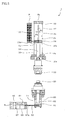
- FIG. 5 is an explanatory view showing the outline of the compression molding apparatus according to this embodiment.
- FIG. 6 is a view showing the manufacturing steps for explaining the method for manufacturing a synthetic resin container according to this embodiment, and shows an example in which a synthetic resin container is manufactured by using the compression molding apparatus shown in FIG. 5 .
- the compression molding apparatus 1 in this embodiment is provided with a pair of molds, i.e. the upper mold 10 and the lower mold 20, as in the case of those shown in the above-mentioned first embodiment.
- the upper mold 10 is attached to the upper mold driving means which is composed of the first cylinder 30 and the second cylinder 35 which are coaxially and serially connected.
- the lower driving means is different from that in the first embodiment.
- the lower mold driving means of this embodiment is provided with a first cylinder 60 and a second cylinder 65 which is connected to this first cylinder 60 through an oil introduction path 63.
- the first cylinder 60 has in its inside a fist piston 61 and a first piston rod 62.
- the lower mold 20 is attached to the front end side of the first piston rod 62.
- the second cylinder 65 has in its inside a second piston 66 and a second piston rod 67.
- the second piston rod 67 is inserted into a second piston rod insertion hole 67a which is provided in the second cylinder 65.
- the second cylinder 65 is provided with the air intake and exhaust ports P 5 and P 6 and the first cylinder 60 is provided with the air intake port P 7 , as shown in the figure.
- the lower mold driving means of this embodiment enables the lower mold 20 to move upward and downward by taking in and exhausting air from these air intake and exhaust ports P 5 , P 6 and P 7 . That is, when compressed air which has been pressurized to a predetermine pressure is flown to the second cylinder 65 from the air intake and exhaust port P 5 of the second cylinder 65, the second piston 66 is moved while air in the second cylinder 65 is exhausted from the air intake and exhaust port P 6 .
- oil stored in the oil introduction path 63 is pressurized by the second piston rod 67 and flown to the first cylinder 60. Due to the hydraulic pressure acted at this time, air in the first cylinder 60 is then exhausted from the air intake and exhaust port P 7 , and the first piston 61 is pushed up, and the lower mold 20 attached to the first piston rod 62 is moved upward. Then, by allowing the air intake exhaust port P 5 to be open to the air and by allowing compressed air to be flown from the air intake and exhaust port P 6 to the second cylinder 65, the lower mold 20 can be moved downward due to the operation reverse to that mentioned above.
- the compression molding apparatus 1 of this embodiment shown in FIG. 5 is provided with the upper driving means which is the same as that of the first embodiment.
- the third embodiment differs from the first embodiment only in the lower driving means.
- the molten resin D is supplied to the lower mold 20 (see FIG. 6(a) ), and then the upper mold 10 is moved downward for a predetermined stroke length (see FIG. 6(b) ).
- the upper driving means is switched to high-pressure driving, whereby a load applied on the upper mold 10 is increased.
- the above-mentioned operation is completely the same as that in the first embodiment.
- the lower mold 20 is moved upward by the lower driving means, thereby allowing clamping to be conducted with the upper mold 10 and the lower mold 20 being close to each other (see FIG. 6(c) ).
- the time required for compression molding can be shortened by allowing clamping to be conducted with the upper mold 10 and the lower mold 20 being close to each other.
- the molten resin D starts to solidify by heat dissipation when it is supplied to the lower mold 20. Therefore, in respect of reduction in molding cycle time but also improvement in moldability, it is extremely effective to complete compression molding as shortly as possible when the molten resin D can be easily subjected to deformation by plasticization.
- the molten resin D is subjected to compression molding into the container M within a cavity formed between the upper mold 10 and the lower mold 20.
- compression molding in order to take the container M out, molds are opened by moving the upper mold 10 upward (see FIG. 6(d) ).
- the compression molding apparatus is returned to the state shown in FIG. 6(a) to repeat compression molding.
- the type of the upper mold driving means is not limited to that mentioned above as far as the upper mold 10 can be supported such that clamping can be conducted against a compression load which has been applied to the lower mold 20. That is, in the first embodiment and the second embodiment, a compression load required for compression molding is generated by the lower driving means, and is applied to the lower mold 20. Therefore, the upper mold driving means is not required to have pressurizing capacity to allow such a high load to be generated.
- the upper driving means means with various mechanisms capable of moving the upper mold 10 upward and downward at a high speed can be used as long as it satisfies the requirement that the upper mold 10 can be supported such that clamping is conducted against a compression load applied to the lower mold 20.
- a lower mold driving means different from that in the first and second embodiments is used.
- the same hydraulic cylinder 40 as that in the first and second embodiments can be used.
- the upper mold 10 is used as a female mold and the lower mold 20 is used as a male mold.
- the molds are not limited thereto, and the upper mold 10 may be used as a male mold and the lower mold 20 may be used as a female mold.
- the present invention can be used particularly preferably in the production of a synthetic resin container by compression molding.
Abstract
Description
- The present invention relates to a compression molding apparatus and a method for manufacturing a synthetic resin container capable of conducting compression molding repeatedly and efficiently even when molds are opened with a sufficient stroke length.
- As disclosed in
Patent Document 1, for example, it is known to cut a resin which has been extruded from an extruder in a predetermined amount and supply the resin between a pair of molds, i.e. upper and lower molds, followed by clamping, thereby to allow the resin to compression molded into a predetermined shape. - Patent Document 1:
JP-A-2000-280248 - In order to take out from molds a molded article which has been molded into a predetermined shape by compression molding, it is required to create a space between an upper mold and a lower mold which is necessary for taking out the molded article. Therefore, after the completion of molding, it is desired that molds be opened with a sufficient stroke length.
However, if the stroke length of mold opening is prolonged and opening and closing of molds is repeated with such a long stroke length, the cycle of molding is prolonged, which is unfavorable in respect of molding efficiency. - On the other hand, in order to shorten the cycle of molding, it suffices that opening and closing operation of molds be conducted at a high speed, thereby to reduce the time required for opening and closing of molds.
However, in such compression molding, generally, a compression molding apparatus is used in which a clank mechanism or a hydraulic cylinder is used to conduct mold opening and closing or clamping. In such an apparatus, if an attempt is made to open and close molds at a high speed while retaining its pressurizing capacity so that a high load which is required for compression molding can be obtained, problems may occur that an apparatus is increased in size, running cost is increased, or the like.
Further, it is considered to conduct opening and closing of molds at a high speed by a driving mechanism in which an air cylinder or a ball screw and a servo motor are combined. However, a driving mechanism which is generally used in which an air cylinder or a ball screw and a servo motor are combined has a limit for generating a high load required for compression molding. - The present invention has been made in view of the above-mentioned circumstances, and an object thereof is to provide a compression molding apparatus capable of mass-producing a molded article in a predetermined shape efficiently while effectively avoiding prolongation of the molding cycle even if opening and closing of molds for taking an molded article out is conducted with a sufficient stroke length when molding a molded article in a predetermined shape by compression molding, and a method for manufacturing a synthetic resin container which can preferably utilize such apparatus.
- The compression molding apparatus according to the present invention has a configuration in which it is provided with a pair of molds, i.e. an upper mold and a lower mold; a lower mold driving means which applies a compression load while moving the lower mold upward during clamping; and an upper mold driving means which supports the upper mold such that clamping is conducted against a compression load applied to the lower mold, after the upper mold is moved downward for a predetermined stroke length.
- The method for manufacturing a synthetic resin container according to the present invention is a method in which a molten resin in a predetermined amount is supplied to a pair of molds, i.e., upper and lower molds provided with a cavity corresponding to a desired container shape, followed by compression molding, wherein after the upper mold is moved downward for a predetermined stroke length such that it approaches the lower mold in which the molten resin has been supplied, a compression load is applied to the lower mold while moving the lower mold upward, and the upper mold is supported so that clamping is conducted against a compression load applied to the lower mold.
- According to the present invention, as mentioned above, compression molding can be repeatedly conducted efficiently, while effectively avoiding prolongation of the molding cycle even if the molds are opened with a sufficient stroke length.
- Therefore, according to the method for manufacturing a synthetic resin container of the present invention, a synthetic resin container with a predetermined shape can be produced with a high productivity.
-
-
FIG. 1 is a schematic explanatory view of a compression molding apparatus according to the present invention; -
FIG. 2 is a view showing the manufacturing steps for explaining the first embodiment of the method for manufacturing a synthetic resin container according to the present invention; -
FIG. 3 is a schematic explanatory view showing the second embodiment of the compression molding apparatus according to the present invention; -
FIG. 4 is a view showing the manufacturing steps for explaining the second embodiment of the method for manufacturing the synthetic resin container according to the present invention; -
FIG. 5 is a schematic explanatory view showing the third embodiment of the compression molding apparatus according to the present invention; and -
FIG. 6 is a view showing the manufacturing steps for explaining the third embodiment of the method for manufacturing the synthetic resin container according to the present invention. - Preferred embodiments of the invention will be explained with reference to the drawings.
- First, an explanation is made on the first embodiment of the compression molding apparatus and the method for manufacturing a synthetic resin container according to the present invention.
Here,FIG. 1 is an explanatory view for showing the outline of the compression molding apparatus according to the present invention.FIG. 2 is a view showing the manufacturing steps for explaining the method for manufacturing a synthetic resin container according to the present invention, showing an example in which a synthetic resin container is manufactured by using the compression molding apparatus shown inFIG.1 . - In this embodiment, a
compression molding apparatus 1 is provided with a pair of molds, i.e. an upper and a lower mold, that is, anupper mold 10 as a female mold and alower mold 20 as a male mold. Thecompression molding apparatus 1 shown in the figures is used for molding a synthetic resin container M in the shape of a thin-wall cup (seeFIG. 2(e) ), and has a configuration in which a cavity corresponding to the outer shape of the container M is formed between theupper mold 10 and thelower mold 20 which are closed. - The synthetic resin container M can be molded by using an arbitral thermoplastic resin which can be subjected to compression molding. Specific examples thereof include polyester-based resins such as polyethylene terephthalate, polybutylene terephthalate and polyethylene terephthalate, polyolefin-based resins such as polypropylene and polyethylene, polycarbonate, polyarylate, polylactate or a copolymer thereof.
- Of such a pair of molds, i.e. the upper and the lower mold, the
lower mold 20 is attached to ahydraulic cylinder 40 as a lower driving means. Thishydraulic cylinder 40, when clamping is conducted, generates a compression load which is required for compression molding while moving thelower mold 20 upward, and applies the load thus generated to thelower mold 20. - The
upper mold 10 is attached to an upper mold driving means which is composed of afirst cylinder 30 and asecond cylinder 35 which are serially and coaxially connected. By this upper mold driving means, theupper mold 10 is moved downward to approach thelower mold 20 during clamping and is moved upward to remote from thelower mold 20 during mold opening. - The
first cylinder 30 has in its inside afirst piston 31 and afirst piston rod 32 which is connected to the middle of the lower surface of thefirst piston 31. Theupper mold 10 is directly attached to the front end of thefirst piston rod 32. - The outer diameter of the
first piston 31 is formed such that it almost corresponds to the inner diameter of thefirst cylinder 30. On the outer circumferential surface of thefirst piston 31, a piston ring (not shown) is provided. Due to the presence of the piston ring, leakage of air or oil is prevented when thefirst piston 31 reciprocates in thefirst cylinder 30. - On the bottom surface of the
first cylinder 30, a first pistonrod insertion hole 32a is provided. Thefirst piston rod 32 is inserted into this first pistonrod insertion hole 32a, leads to the outside of thefirst cylinder 30, thereby allowing theupper mold 10 to be attached thereto. At this time, on the inner circumference surface of the first pistonrod insertion hole 32a, leakage of air from the first pistonrod insertion hole 32a can be prevented by provision of a sealing element such as an O-ring (not shown). - A
second cylinder 35 has in its inside asecond piston 36 and asecond piston rod 37 connected to the middle of the lower surface of thesecond piston 36. Prevention of air leakage by allowing the outer diameter of thesecond piston 36 to approximately correspond to the inner diameter of thesecond cylinder 35 and by providing a piston ring on the outer circumferential surface of thesecond piston 36 is the same as that explained for thefirst cylinder 30. - The
first cylinder 30 and thesecond cylinder 35 are separated by apartition wall 34. In the middle of thispartition wall 34, a second pistonrod insertion hole 37a is formed. Thesecond piston rod 37 is inserted into this second pistonrod insertion hole 37a so that it connects to the inside of thefirst cylinder 30. - In the
partition wall 34, anoil introduction path 33a is formed which leads to anoil tank 33 in which oil is stored. Thisoil introduction path 33a is intercommunicated with the second pistonrod insertion hole 37a, whereby the oil which has been stored in theoil tank 33 can be flown to thefirst cylinder 30 after passing theoil introduction path 33a and the second pistonrod insertion hole 37a. - In each of the upper surface of the
oil tank 33, the upper surface of thesecond cylinder 35, the lower side surface of thesecond cylinder 35 and the lower side surface of thefirst cylinder 30, air intake and exhaust ports P1, P2, P3 and P4 are provided. The above-mentioned upper mold driving means enable theupper mold 10 to move upward and downward by conducting air intake and exhaust from these air intake and exhaust ports P1, P2, P3 and P4. - Next, an explanation will be made on the operation of the
compression molding apparatus 1 with the above-mentioned configuration. At the same time, an explanation is made on the first embodiment of the method for manufacturing a synthetic resin container which can be preferably implemented utilizing thecompression molding apparatus 1 shown inFIG. 1 . - At first, a container M which has been molded into a predetermined shape in a previous molding cycle, is taken out. On the
lower mold 20 which stands by while keeping the opened state, a molten resin D which has been extruded from an extruder (not shown) and cut into a predetermined resin amount is supplied (seeFIG. 2(a) ). At this time, the air intake and exhaust ports P1 and P2 are open to the air, and from the air intake and exhaust ports P3 and P4, air is taken in each of thecylinders upper mold 10 stands by at a position where a space which is sufficient for taking the container M out is formed between it and thelower mold 20. - Subsequently, after the supply of the molten resin D, while keeping the air intake and exhaust port P2 open to the air and keeping the air intake and exhaust port P3 to the air intake mode, and the air intake and exhaust port P1 is switched to the air intake mode and the air intake and exhaust port P4 is switched to be open to the air. Then, air is taken in the
oil tank 33 from the air intake and exhaust port P1, and air in thefirst cylinder 30 is exhausted from the air intake and exhaust port P4. At the same time, oil in theoil tank 33 is flown into thefirst cylinder 30 after passing theoil introduction path 33a and the second pistonrod insertion hole 37a.
As a result, thefirst piston 31 is pushed down, and theupper mold 10 which is attached to thefirst piston rod 32 is moved downward in a direction in which it approaches the lower mold 20 (seeFIG. 2(b) ). - Here, the speed at which the
upper mold 10 is moved downward depends on the amount of air taken from the air intake and exhaust port P1 and the amount of air exhausted from the air intake and exhaust port P4. It is possible to allow theupper mold 10 to move downward with a narrower space than a clank mechanism and at a speed significantly higher than the case in which the molds are opened and closed by means of a hydraulic cylinder. As for the air intake and exhaust from the air intake and exhaust port P1 and the air intake and exhaust port P4, pressure is increased or decreased according to need, thereby to increase or decrease the amount of air taken in and exhausted from the air intake and exhaust port P1 and the air intake and exhaust port P4, thereby to adjust the speed at which theupper mold 10 is moved downward. By increasing the amount of air taken in and exhausted from the air intake and exhaust port P1 and the air intake and exhaust port P4, it is possible to allow theupper mold 10 to move downward at a higher speed. - At any rate, according to this embodiment, the high-speed operation of the
upper mold 10 becomes possible. Therefore, if molds are opened with a sufficient stroke length to take the molded container M out, the time required for allowing theupper mold 10 and thelower mold 20 to approach for clamping is reduced, whereby the molding cycle can be shortened.
Although not particularly shown, theoil introduction path 33a may be provided with a pump or an opening and closing valve in the midway thereof, whereby the amount of oil flowing in theoil introduction path 33a can be appropriately adjusted and the operation speed of theupper mold 10 can be adjusted. - At a point where the
upper mold 10 is moved downward for a predetermined stroke length, air intake from the air intake and exhaust port P3 is stopped and the air intake and exhaust port P3 is then allowed to be open to the air. At the same time, compressed air which has been pressurized to a predetermined pressure is flown from the air intake and exhaust port P2 into thesecond cylinder 35. While air of thesecond cylinder 35 is exhausted from the air intake and exhaust port P3, thesecond piston 36 is pushed down, whereby thesecond piston rod 37 is inserted into thefirst cylinder 30 after passing the second pistonrod insertion hole 37a (seeFIG. 2(c) ). - At this time, the
first cylinder 30 is filled with oil. Therefore, when thesecond piston rod 37 is inserted into thefirst cylinder 30, a hydraulic pressure is applied to thefirst piston 31. If the inner diameter of thesecond cylinder 35 is assumed to be φ1 and the outer diameter of thesecond piston rod 37 is assumed to be φ2, the hydraulic pressure [Poil] acting on thefirst piston 31 is increased by φ1 2/φ2 2 times [Poil = (φ/1 2/φ 2 2) × Pair] based on the pressure [Pair] of the compressed air flowing in thesecond cylinder 35. - As mentioned above, in the upper mold driving means provided in the
compression molding apparatus 1 of this embodiment, it is possible to switch from low-pressure driving to high-pressure driving by appropriately opening and closing air intake and exhaust ports P1, P2, P3 and P4. Then, the upper mold driving means which has been switched to high-pressure driving serves as a pressure-increasing means, and increases a load applied to theupper mold 10. - During clamping, when the
upper mold 10 moves downward for a predetermined stroke length, the upper mold driving means is switched to the high-pressure driving, thereby to allow the load applied to theupper mold 10 to be increased. On the other hand, simultaneously with or after switching the upper mold driving means to high-pressure driving, thehydraulic cylinder 40 to which thelower mold 20 has been attached is driven, a load which is required to compression molding is applied to thelower mold 20 while moving thelower mold 20 to move upward (seeFIG. 2(d) ). - At this time, a load applied to the
upper mold 10 is increased such that it exceeds a compression load applied to thelower mold 20. As a result, theupper mold 10 is supported by the upper mold driving means such that clamping is conducted against a compression load applied to thelower mold 20, whereby the molten resin D is compression-molded into a container M with a predetermined shape in the cavity between theupper mold 10 and thelower mold 20. - After compression molding is completed, the
upper mold 10 is moved upward to open the mold in order to take the molded container M out (seeFIG. 2(e) ).
In order to open the molds, by allowing air to be exhausted from the air intake and exhaust port P2 while allowing air to be intaken from the air intake and exhaust port P3 to thesecond cylinder 35, thereby to allow thesecond piston 36 to be pushed up. At the same time, by allowing air to be exhausted from the air exhaust port P1 which is open to the air, while allowing air to be taken in from the air intake and exhaust port P4 to thefirst cylinder 30, the oil in thefirst cylinder 30 is returned to theoil tank 33, thereby to push up thefirst piston 31. As a result, theupper mold 10 is moved upward in such a manner that it is separated from thelower mold 20.
During the mold opening, thelower mold 20 is moved downward to a stand-by position by driving the lower mold driving means. - After the molds are opened and the container M is taken out, the compression molding apparatus is returned to the state shown in
FIG. 2(a) to repeat compression molding. - In this embodiment in which compression molding is conducted in the above-mentioned way, the upper mold driving means which is provided in the
compression molding apparatus 1 enables high-speed operation of theupper mold 10, and can apply a necessary load to theupper mold 10 by switching to high-pressure driving. Therefore, even if the molds are opened with a sufficient stroke length to take a molded article out, the molding cycle is effectively prevented from being prolonged, a compression molding is repeated efficiently, whereby the synthetic resin container M in a predetermined shape can be mass-produced with a high productivity. - Further, in this embodiment, there are advantages that, when the upper mold driving means is switched to high-pressure driving to increase a load to be applied to the
upper mold 10, by appropriately adjusting the timing or degree of increase, the fine adjustment of the clamping pressure can be conducted taking into consideration the balance with the compression load applied to thelower mold 20.
When theupper mold 10 is moved downward for a predetermined stroke length, a load applied to theupper mold 10 is increased and, at the same time, thelower mold 20 is moved upward, thereby to enable clamping while allowing theupper mold 10 and thelower mold 20 to approach each other. As a result, after theupper mold 10 is moved downward for a predetermined stroke length for a short period of time, the time required for allowing the molten resin M to be molded into the synthetic resin container M in a predetermined shape can also be reduced. This will be explained in detail in the third embodiment, given later. - Next, the second embodiment of a compression molding apparatus and the method for manufacturing a synthetic resin container according to the present invention will be explained.
Here,FIG. 3 is an explanatory view for showing the outline of the compression molding apparatus according to this embodiment. Further,FIG. 4 is a view for showing the manufacturing steps for explaining the method for manufacturing a synthetic resin container according to this embodiment, and shows an example in which a synthetic resin container is manufactured by using the compression molding apparatus shown inFIG. 3 . - The
compression molding apparatus 1 in this embodiment is provided with a pair of molds, i.e. theupper mold 10 and thelower mold 20, as in the case of those shown in the above-mentioned first embodiment. Provision of thelower mold 20 to thehydraulic cylinder 40 as the lower driving means is the same as in the above-mentioned first embodiment, and hence, a detailed explanation thereof is omitted. - In this embodiment, the
upper mold 10 is attached to anair cylinder 50 as the upper mold driving means. This embodiment differs from the above-mentioned first embodiment in this point.
Anair cylinder 50 is mounted vertically relative to the base table 55. To the front end side of anoutput axis 51 of theair cylinder 50, theupper mold 10 is attached. When theair cylinder 50 is driven, theupper mold 10 is moved up and down such that it remotes from thelower mold 20, thereby enabling high-speed operation of theupper mold 10. - After the
upper mold 10 is moved downward for a predetermined stroke length, thehydraulic cylinder 40 to which thelower mold 20 has been attached is driven, a load necessary for compression molding is applied to thelower mold 20 while moving thelower mold 20 upward. At this time, in order to support theupper mold 10 so that clamping is conducted against a compression load applied to thelower mold 20, the upper mold driving means has a fixing means to prevent the upward movement of theupper mold 10. - In the
compression molding apparatus 1 shown inFIG. 3 , engagement bars 53 which are engaged with engagement tables 52 provided on the base part side of anoutput axis 51 and serve to suppress the upward movement of theupper mold 10 are provided on the left and right of the base table 55 as fixing means such that they are opposed to each other. Theengagement bar 53 is provided such that it can move forward and backward in the horizontal direction by means of anair cylinder 54. The engagement bars 53 move forward when theupper mold 10 is moved downward for a predetermined stroke length, and when the engagement bars 53 are engaged with the upper surface side of the engagement table 52, the engagement bars 53 serve to suppress the upward movement of the upper mold 10 (seeFIG. 4(c) ). - Subsequently, operation of the
compression molding apparatus 1 with the above-mentioned configuration will be explained. At the same time, the second embodiment of the method for manufacturing a synthetic resin container according to the present invention which can be preferably implemented by using thecompression molding apparatus 1 shown inFIG. 3 will be explained. - As in the same manner as the above-mentioned first embodiment, at first, the molten resin D is supplied to the lower mold 20 (see
FIG. 4(a) ). Subsequently, theair cylinder 50 as the upper mold driving means is driven to allow theupper mold 10 to move downward (seeFIG. 4(b) ). - Subsequently, when the
upper mold 10 is moved downward for a predetermined stroke length, theair cylinder 54 is driven to allow theengagement bar 53 to move forward. As a result, theengagement bar 53 is engaged with the upper surface of the engagement table 52 provided on the base part of theoutput axis 51, whereby the upward movement of theupper mold 10 is suppressed (seeFIG. 4(c) ).
On the other hand, while allowing thelower mold 20 to move upward by driving thehydraulic cylinder 40 to which thelower mold 20 has been attached, a load necessary for compression molding is applied to the lower mold 20 (seeFIG. 4(d) ). - As a result, in order to attain clamping against the compression load which has been applied to the
lower mold 20, theupper mold 10 is supported by the upper driving means, whereby the molten resin D is compression-molded into the container M in a predetermined shape in a cavity formed between theupper mold 10 and thelower mold 20. - When the compression molding is completed, the
air cylinder 54 is driven to allow theengagement bar 53 to move backward, thereby to cancel the engagement of theengagement bar 53 with the engagement table 52. Subsequently, theair cylinder 50 is driven to allow theupper mold 10 to move upward to conduct mold opening, whereby the molded container M is taken out (seeFIG. 4(e) ).
Further, in mold opening, thelower mold 20 is also moved downward to the stand-by position by driving the lower driving means. - If the molds are opened and the container M is taken out, the compression molding apparatus is returned to the state shown in
FIG. 4(a) , and compression molding is repeated. - In this embodiment in which compression molding is conducted as mentioned above, the
air cylinder 50 as the upper mold driving means which is provided in thecompression molding apparatus 1 enables high-speed operation of theupper mold 10. Then, when theupper mold 10 is moved downward for a predetermined stroke length, theupper mold 10 is prevented from moving upward by the fixing means, whereby clamping is conducted against a compression load applied to thelower mold 20.
Therefore, if an attempt is made to allow the molds to open with a sufficient stroke length in order to take a molded article out, prolongation of the molding cycle can be effectively prevented, compression molding can be repeatedly conducted efficiently, whereby the synthetic resin container M in a predetermined shape can be mass-produced with a high productivity. - The third embodiment of the compression molding apparatus and the method for manufacturing a synthetic resin container according to the present invention will be explained.
Here,FIG. 5 is an explanatory view showing the outline of the compression molding apparatus according to this embodiment.FIG. 6 is a view showing the manufacturing steps for explaining the method for manufacturing a synthetic resin container according to this embodiment, and shows an example in which a synthetic resin container is manufactured by using the compression molding apparatus shown inFIG. 5 . - The
compression molding apparatus 1 in this embodiment is provided with a pair of molds, i.e. theupper mold 10 and thelower mold 20, as in the case of those shown in the above-mentioned first embodiment. As in the first embodiment, theupper mold 10 is attached to the upper mold driving means which is composed of thefirst cylinder 30 and thesecond cylinder 35 which are coaxially and serially connected. In this embodiment, the lower driving means is different from that in the first embodiment. - The lower mold driving means of this embodiment is provided with a
first cylinder 60 and asecond cylinder 65 which is connected to thisfirst cylinder 60 through anoil introduction path 63.
Thefirst cylinder 60 has in its inside afist piston 61 and afirst piston rod 62. Thelower mold 20 is attached to the front end side of thefirst piston rod 62. On the other hand, thesecond cylinder 65 has in its inside asecond piston 66 and asecond piston rod 67. Thesecond piston rod 67 is inserted into a second pistonrod insertion hole 67a which is provided in thesecond cylinder 65. When thesecond piston rod 67 moves in the right direction in the figure, the oil stored in theoil introduction path 63 is pressurized to flow in thefirst cylinder 60. - The
second cylinder 65 is provided with the air intake and exhaust ports P5 and P6 and thefirst cylinder 60 is provided with the air intake port P7, as shown in the figure. The lower mold driving means of this embodiment enables thelower mold 20 to move upward and downward by taking in and exhausting air from these air intake and exhaust ports P5, P6 and P7.
That is, when compressed air which has been pressurized to a predetermine pressure is flown to thesecond cylinder 65 from the air intake and exhaust port P5 of thesecond cylinder 65, thesecond piston 66 is moved while air in thesecond cylinder 65 is exhausted from the air intake and exhaust port P6. As a result, oil stored in theoil introduction path 63 is pressurized by thesecond piston rod 67 and flown to thefirst cylinder 60. Due to the hydraulic pressure acted at this time, air in thefirst cylinder 60 is then exhausted from the air intake and exhaust port P7, and thefirst piston 61 is pushed up, and thelower mold 20 attached to thefirst piston rod 62 is moved upward. Then, by allowing the air intake exhaust port P5 to be open to the air and by allowing compressed air to be flown from the air intake and exhaust port P6 to thesecond cylinder 65, thelower mold 20 can be moved downward due to the operation reverse to that mentioned above.
The pressure of the compressed air [Pair] flown into thesecond cylinder 65 and the hydraulic pressure [Poil] acting on thefirst piston 61 satisfies the relationship Poil = (φ 3 2/φ4 2) × Pair, assuming that the inner diameter of thesecond cylinder 65 is φ3 and the outer diameter of thesecond piston rod 67 is φ4. - Next, operation of the
compression molding apparatus 1 with the above-mentioned configuration will be explained, and the third embodiment of the method for manufacturing a synthetic resin container according to the present invention which can be preferably implemented by using thecompression molding apparatus 1 shown inFIG. 5 will be explained.
Thecompression molding apparatus 1 of this embodiment shown inFIG. 5 is provided with the upper driving means which is the same as that of the first embodiment. The third embodiment differs from the first embodiment only in the lower driving means. Therefore, although it is possible to implement the method for manufacturing a synthetic resin container according to the first embodiment, in this embodiment, an explanation is made on an embodiment in which when theupper mold 10 is moved downward for a predetermined stroke length, thelower mold 20 is moved upward while increasing a load applied to theupper mold 10, whereby clamping is conducted while theupper mold 10 and thelower mold 20 are close to each other. - In this embodiment, at first, the molten resin D is supplied to the lower mold 20 (see
FIG. 6(a) ), and then theupper mold 10 is moved downward for a predetermined stroke length (seeFIG. 6(b) ). When theupper mold 10 is moved downward for a predetermined stroke length, the upper driving means is switched to high-pressure driving, whereby a load applied on theupper mold 10 is increased. The above-mentioned operation is completely the same as that in the first embodiment. - In this embodiment, simultaneously with or almost simultaneously with an increase in the load applied on the
upper load 10, thelower mold 20 is moved upward by the lower driving means, thereby allowing clamping to be conducted with theupper mold 10 and thelower mold 20 being close to each other (seeFIG. 6(c) ).
In this way, in the final stage of compression molding to mold the molten resin D into a container with a thin-wall cup shape where the largest load is required, it is possible to apply a sufficient load to the molten resin D, and the time required for compression molding can be shortened by allowing clamping to be conducted with theupper mold 10 and thelower mold 20 being close to each other. The molten resin D starts to solidify by heat dissipation when it is supplied to thelower mold 20. Therefore, in respect of reduction in molding cycle time but also improvement in moldability, it is extremely effective to complete compression molding as shortly as possible when the molten resin D can be easily subjected to deformation by plasticization. - When clamping is conducted with the
upper mold 10 and thelower mold 20 being close to each other, the molten resin D is subjected to compression molding into the container M within a cavity formed between theupper mold 10 and thelower mold 20. When compression molding is completed, in order to take the container M out, molds are opened by moving theupper mold 10 upward (seeFIG. 6(d) ). When the molds are opened and the container M is taken out, the compression molding apparatus is returned to the state shown inFIG. 6(a) to repeat compression molding. - Hereinabove, the present invention is explained with reference to preferred embodiments. The present invention is not limited to the above-mentioned embodiment, and it is needless to say various modifications are possible within the scope of the present invention.
- For example, in the above-mentioned first embodiment and the second embodiment, the type of the upper mold driving means is not limited to that mentioned above as far as the
upper mold 10 can be supported such that clamping can be conducted against a compression load which has been applied to thelower mold 20.
That is, in the first embodiment and the second embodiment, a compression load required for compression molding is generated by the lower driving means, and is applied to thelower mold 20. Therefore, the upper mold driving means is not required to have pressurizing capacity to allow such a high load to be generated. Therefore, as for the upper driving means, means with various mechanisms capable of moving theupper mold 10 upward and downward at a high speed can be used as long as it satisfies the requirement that theupper mold 10 can be supported such that clamping is conducted against a compression load applied to thelower mold 20. - In the above-mentioned third embodiment, a lower mold driving means different from that in the first and second embodiments is used. However, as far as the time required for compression molding can be reduced by allowing, after the
upper mold 10 to move downward at a high speed for a predetermined stroke length, clamping to be conducted with theupper mold 10 and thelower mold 20 being close to each other, the samehydraulic cylinder 40 as that in the first and second embodiments can be used. - In the above-mentioned embodiment, the
upper mold 10 is used as a female mold and thelower mold 20 is used as a male mold. The molds are not limited thereto, and theupper mold 10 may be used as a male mold and thelower mold 20 may be used as a female mold. - The present invention can be used particularly preferably in the production of a synthetic resin container by compression molding.
Claims (9)
- A compression molding apparatus comprising:a pair of molds, i.e. an upper mold and a lower mold;a lower mold driving means which applies a compression load while moving the lower mold upward during clamping; andan upper mold driving means which supports the upper mold such that clamping is conducted against a compression load applied to the lower mold, after the upper mold is moved downward for a predetermined stroke length.
- The compression molding apparatus according to claim 1, wherein the upper mold driving means is provided with a pressure increasing means which applies a load higher than a compression load applied to the lower mold.
- The compression molding apparatus according to claim 2, wherein the upper mold driving means can be switched from low-pressure driving to high-pressure driving, and a load applied to the upper mold can be increased by switching to the high-pressure driving.
- The compression molding apparatus according to any one of claims 1 to 3, wherein the load applied to the upper mold is increased and the lower mold is moved upward when the upper mold is moved downward for a predetermined stroke length, whereby clamping is conducted with the upper mold and the lower mold being close to each other.
- The compression molding apparatus according to claim 1, wherein the upper mold driving means is provided with a fixing means which prevents the upper mold from moving upward when clamping is conducted.
- A method for manufacturing a synthetic resin container in which a molten resin in a predetermined amount is supplied to a pair of molds, i.e. upper and lower molds provided with a cavity corresponding to a desired container shape, followed by compression molding, wherein
after the upper mold is moved downward for a predetermined stroke length such that it approaches the lower mold in which the molten resin has been supplied,
a compression load is applied to the lower mold while moving the lower load upward, and
the upper mold is supported so that clamping is conducted against a compression load applied to the lower mold. - The method for manufacturing a synthetic resin container according to claim 6, wherein clamping is conducted by applying to the upper mold a load larger than a compression load applied to the lower mold.
- The method for manufacturing a synthetic resin container according to claim 6 or claim 7, wherein, when the upper mold is moved downward for a predetermined stroke length, clamping is conducted with the upper mold and the lower mold being close to each other by increasing the load applied to the upper mold and by moving the lower mold to move upward.
- The method for manufacturing a synthetic resin container according to claim 6, wherein clamping is conducted by preventing the upper mold from moving upward.
Applications Claiming Priority (2)
| Application Number | Priority Date | Filing Date | Title |
|---|---|---|---|
| JP2008186883 | 2008-07-18 | ||
| PCT/JP2009/053662 WO2010007806A1 (en) | 2008-07-18 | 2009-02-27 | Compression molding apparatus, and synthetic resin container manufacturing method |
Publications (4)
| Publication Number | Publication Date |
|---|---|
| EP2322336A1 true EP2322336A1 (en) | 2011-05-18 |
| EP2322336A4 EP2322336A4 (en) | 2012-02-08 |
| EP2322336B1 EP2322336B1 (en) | 2017-04-26 |
| EP2322336B8 EP2322336B8 (en) | 2017-07-26 |
Family
ID=41550215
Family Applications (1)
| Application Number | Title | Priority Date | Filing Date |
|---|---|---|---|
| EP09797734.2A Not-in-force EP2322336B8 (en) | 2008-07-18 | 2009-02-27 | Compression molding apparatus |
Country Status (6)
| Country | Link |
|---|---|
| US (1) | US8652390B2 (en) |
| EP (1) | EP2322336B8 (en) |
| JP (2) | JP5482653B2 (en) |
| CN (1) | CN102089133B (en) |
| ES (1) | ES2634661T3 (en) |
| WO (1) | WO2010007806A1 (en) |
Citations (2)
| Publication number | Priority date | Publication date | Assignee | Title |
|---|---|---|---|---|
| US4615928A (en) * | 1982-09-27 | 1986-10-07 | Toyo Seikan Kaisha, Ltd. | Method and apparatus for making a plastic container and an improvement thereof |
| US5770130A (en) * | 1993-10-14 | 1998-06-23 | Owens-Illinois Closure Inc. | Method and apparatus for compression molding plastic articles |
Family Cites Families (8)
| Publication number | Priority date | Publication date | Assignee | Title |
|---|---|---|---|---|
| JPS58192699A (en) | 1982-05-07 | 1983-11-10 | Iwatani & Co | Method and device for forming and working with press |
| JPS60166271A (en) | 1984-02-10 | 1985-08-29 | 工業技術院長 | Manufacture of ceramic sintered body |
| JPS6273920U (en) * | 1985-10-29 | 1987-05-12 | ||
| JP2774965B2 (en) * | 1989-04-20 | 1998-07-09 | 株式会社富士通宮城エレクトロニクス | Resin sealing device |
| JPH09277357A (en) * | 1996-04-11 | 1997-10-28 | Mitsubishi Plastics Ind Ltd | Stretch blow molding method and apparatus therefor |
| JP3044344B2 (en) * | 1998-09-10 | 2000-05-22 | 有限会社中部エンジニアリング工業 | Injection molding machine |
| JP3674385B2 (en) | 1999-04-02 | 2005-07-20 | 東洋製罐株式会社 | Synthetic resin feeder |
| JP3716749B2 (en) * | 2001-02-15 | 2005-11-16 | 東洋製罐株式会社 | Method and apparatus for compression molding of preform for blow molded container |
-
2009
- 2009-02-27 CN CN200980126590.XA patent/CN102089133B/en not_active Expired - Fee Related
- 2009-02-27 US US12/737,474 patent/US8652390B2/en not_active Expired - Fee Related
- 2009-02-27 WO PCT/JP2009/053662 patent/WO2010007806A1/en active Application Filing
- 2009-02-27 EP EP09797734.2A patent/EP2322336B8/en not_active Not-in-force
- 2009-02-27 ES ES09797734.2T patent/ES2634661T3/en active Active
- 2009-02-27 JP JP2010520790A patent/JP5482653B2/en active Active
-
2013
- 2013-12-20 JP JP2013263564A patent/JP5679038B2/en active Active
Patent Citations (2)
| Publication number | Priority date | Publication date | Assignee | Title |
|---|---|---|---|---|
| US4615928A (en) * | 1982-09-27 | 1986-10-07 | Toyo Seikan Kaisha, Ltd. | Method and apparatus for making a plastic container and an improvement thereof |
| US5770130A (en) * | 1993-10-14 | 1998-06-23 | Owens-Illinois Closure Inc. | Method and apparatus for compression molding plastic articles |
Non-Patent Citations (1)
| Title |
|---|
| See also references of WO2010007806A1 * |
Also Published As
| Publication number | Publication date |
|---|---|
| EP2322336B8 (en) | 2017-07-26 |
| JP5482653B2 (en) | 2014-05-07 |
| CN102089133A (en) | 2011-06-08 |
| JPWO2010007806A1 (en) | 2012-01-05 |
| WO2010007806A1 (en) | 2010-01-21 |
| CN102089133B (en) | 2014-03-12 |
| JP5679038B2 (en) | 2015-03-04 |
| US8652390B2 (en) | 2014-02-18 |
| EP2322336A4 (en) | 2012-02-08 |
| EP2322336B1 (en) | 2017-04-26 |
| ES2634661T3 (en) | 2017-09-28 |
| US20110121489A1 (en) | 2011-05-26 |
| JP2014076664A (en) | 2014-05-01 |
Similar Documents
| Publication | Publication Date | Title |
|---|---|---|
| EP3616881B1 (en) | Liquid container manufacturing method | |
| JP2010515602A (en) | Injection mold and injection molding method | |
| ES2225769T3 (en) | MOLDING AND MOLDING METHOD BY INJECTION-COMPRESSION. | |
| WO2008050659A1 (en) | Die cast machine and die cast molding method | |
| US10279532B2 (en) | Blow molding device | |
| WO2018042807A1 (en) | Liquid blow molding method | |
| CN102712122B (en) | Injection moulding method | |
| US20160082644A1 (en) | Apparatus and method for fabricating containers | |
| US20060204605A1 (en) | Porous member for a post-molding molded article conditioning apparatus with an integrally formed cooling structure | |
| CN102275274A (en) | Injection mechanism with ultrahigh injection volume and squeezing molding technology of ultra-large plastic products | |
| CN101304864A (en) | Injection impact compression moulding | |
| US8652390B2 (en) | Synthetic resin container manufacturing method | |
| KR102337121B1 (en) | Injection blow molding device | |
| US20140322375A1 (en) | Angled-outward toggle clamping type vertical injection molding machine | |
| EP3616880B1 (en) | Liquid container manufacturing method | |
| CN110545983B (en) | Method for manufacturing container filled with liquid | |
| CN109562558B (en) | Liquid blow molding method | |
| CN103317686B (en) | Injection (mo(u)lding) machine | |
| CN105102203A (en) | Apparatus and method for fabricating and filling containers | |
| CN109605695B (en) | Multi-stage mold locking molding method for injection molding machine | |
| JP2005144549A (en) | Apparatus, die and method for forming superposed sheets by hydraulic pressure | |
| CN103857515A (en) | Injection apparatus | |
| EP2769822A1 (en) | Injection molding machine | |
| JP5605445B2 (en) | Die casting machine and die casting method | |
| CN201036910Y (en) | High-speed injection machine |
Legal Events
| Date | Code | Title | Description |
|---|---|---|---|
| PUAI | Public reference made under article 153(3) epc to a published international application that has entered the european phase |
Free format text: ORIGINAL CODE: 0009012 |
|
| 17P | Request for examination filed |
Effective date: 20110113 |
|
| AK | Designated contracting states |
Kind code of ref document: A1 Designated state(s): AT BE BG CH CY CZ DE DK EE ES FI FR GB GR HR HU IE IS IT LI LT LU LV MC MK MT NL NO PL PT RO SE SI SK TR |
|
| AX | Request for extension of the european patent |
Extension state: AL BA RS |
|
| DAX | Request for extension of the european patent (deleted) | ||
| A4 | Supplementary search report drawn up and despatched |
Effective date: 20120106 |
|
| RIC1 | Information provided on ipc code assigned before grant |
Ipc: B29C 43/36 20060101ALI20120102BHEP Ipc: B30B 1/32 20060101ALI20120102BHEP Ipc: B22D 17/26 20060101ALI20120102BHEP Ipc: B29C 43/32 20060101AFI20120102BHEP |
|
| RAP1 | Party data changed (applicant data changed or rights of an application transferred) |
Owner name: TOYO SEIKAN KAISHA, LTD. |
|
| GRAP | Despatch of communication of intention to grant a patent |
Free format text: ORIGINAL CODE: EPIDOSNIGR1 |
|
| INTG | Intention to grant announced |
Effective date: 20161128 |
|
| GRAJ | Information related to disapproval of communication of intention to grant by the applicant or resumption of examination proceedings by the epo deleted |
Free format text: ORIGINAL CODE: EPIDOSDIGR1 |
|
| GRAR | Information related to intention to grant a patent recorded |
Free format text: ORIGINAL CODE: EPIDOSNIGR71 |
|
| GRAS | Grant fee paid |
Free format text: ORIGINAL CODE: EPIDOSNIGR3 |
|
| GRAA | (expected) grant |
Free format text: ORIGINAL CODE: 0009210 |
|
| INTC | Intention to grant announced (deleted) | ||
| INTG | Intention to grant announced |
Effective date: 20170315 |
|
| RAP1 | Party data changed (applicant data changed or rights of an application transferred) |
Owner name: TOYO SEIKAN GROUP HOLDINGS, LTD. |
|
| AK | Designated contracting states |
Kind code of ref document: B1 Designated state(s): AT BE BG CH CY CZ DE DK EE ES FI FR GB GR HR HU IE IS IT LI LT LU LV MC MK MT NL NO PL PT RO SE SI SK TR |
|
| REG | Reference to a national code |
Ref country code: GB Ref legal event code: FG4D |
|
| REG | Reference to a national code |
Ref country code: CH Ref legal event code: EP |
|
| REG | Reference to a national code |
Ref country code: AT Ref legal event code: REF Ref document number: 887478 Country of ref document: AT Kind code of ref document: T Effective date: 20170515 |
|
| REG | Reference to a national code |
Ref country code: IE Ref legal event code: FG4D |
|
| RAP2 | Party data changed (patent owner data changed or rights of a patent transferred) |
Owner name: TOYO SEIKAN GROUP HOLDINGS, LTD. |
|
| REG | Reference to a national code |
Ref country code: DE Ref legal event code: R096 Ref document number: 602009045736 Country of ref document: DE |
|
| REG | Reference to a national code |
Ref country code: NL Ref legal event code: MP Effective date: 20170426 |
|
| REG | Reference to a national code |
Ref country code: LT Ref legal event code: MG4D |
|
| REG | Reference to a national code |
Ref country code: AT Ref legal event code: MK05 Ref document number: 887478 Country of ref document: AT Kind code of ref document: T Effective date: 20170426 |
|
| REG | Reference to a national code |
Ref country code: ES Ref legal event code: FG2A Ref document number: 2634661 Country of ref document: ES Kind code of ref document: T3 Effective date: 20170928 |
|
| PG25 | Lapsed in a contracting state [announced via postgrant information from national office to epo] |
Ref country code: NL Free format text: LAPSE BECAUSE OF FAILURE TO SUBMIT A TRANSLATION OF THE DESCRIPTION OR TO PAY THE FEE WITHIN THE PRESCRIBED TIME-LIMIT Effective date: 20170426 |
|
| PG25 | Lapsed in a contracting state [announced via postgrant information from national office to epo] |
Ref country code: AT Free format text: LAPSE BECAUSE OF FAILURE TO SUBMIT A TRANSLATION OF THE DESCRIPTION OR TO PAY THE FEE WITHIN THE PRESCRIBED TIME-LIMIT Effective date: 20170426 Ref country code: NO Free format text: LAPSE BECAUSE OF FAILURE TO SUBMIT A TRANSLATION OF THE DESCRIPTION OR TO PAY THE FEE WITHIN THE PRESCRIBED TIME-LIMIT Effective date: 20170726 Ref country code: LT Free format text: LAPSE BECAUSE OF FAILURE TO SUBMIT A TRANSLATION OF THE DESCRIPTION OR TO PAY THE FEE WITHIN THE PRESCRIBED TIME-LIMIT Effective date: 20170426 Ref country code: GR Free format text: LAPSE BECAUSE OF FAILURE TO SUBMIT A TRANSLATION OF THE DESCRIPTION OR TO PAY THE FEE WITHIN THE PRESCRIBED TIME-LIMIT Effective date: 20170727 Ref country code: HR Free format text: LAPSE BECAUSE OF FAILURE TO SUBMIT A TRANSLATION OF THE DESCRIPTION OR TO PAY THE FEE WITHIN THE PRESCRIBED TIME-LIMIT Effective date: 20170426 Ref country code: FI Free format text: LAPSE BECAUSE OF FAILURE TO SUBMIT A TRANSLATION OF THE DESCRIPTION OR TO PAY THE FEE WITHIN THE PRESCRIBED TIME-LIMIT Effective date: 20170426 |
|
| PG25 | Lapsed in a contracting state [announced via postgrant information from national office to epo] |
Ref country code: IS Free format text: LAPSE BECAUSE OF FAILURE TO SUBMIT A TRANSLATION OF THE DESCRIPTION OR TO PAY THE FEE WITHIN THE PRESCRIBED TIME-LIMIT Effective date: 20170826 Ref country code: SE Free format text: LAPSE BECAUSE OF FAILURE TO SUBMIT A TRANSLATION OF THE DESCRIPTION OR TO PAY THE FEE WITHIN THE PRESCRIBED TIME-LIMIT Effective date: 20170426 Ref country code: LV Free format text: LAPSE BECAUSE OF FAILURE TO SUBMIT A TRANSLATION OF THE DESCRIPTION OR TO PAY THE FEE WITHIN THE PRESCRIBED TIME-LIMIT Effective date: 20170426 Ref country code: BG Free format text: LAPSE BECAUSE OF FAILURE TO SUBMIT A TRANSLATION OF THE DESCRIPTION OR TO PAY THE FEE WITHIN THE PRESCRIBED TIME-LIMIT Effective date: 20170726 Ref country code: PL Free format text: LAPSE BECAUSE OF FAILURE TO SUBMIT A TRANSLATION OF THE DESCRIPTION OR TO PAY THE FEE WITHIN THE PRESCRIBED TIME-LIMIT Effective date: 20170426 |
|
| REG | Reference to a national code |
Ref country code: DE Ref legal event code: R097 Ref document number: 602009045736 Country of ref document: DE |
|
| PG25 | Lapsed in a contracting state [announced via postgrant information from national office to epo] |
Ref country code: RO Free format text: LAPSE BECAUSE OF FAILURE TO SUBMIT A TRANSLATION OF THE DESCRIPTION OR TO PAY THE FEE WITHIN THE PRESCRIBED TIME-LIMIT Effective date: 20170426 Ref country code: CZ Free format text: LAPSE BECAUSE OF FAILURE TO SUBMIT A TRANSLATION OF THE DESCRIPTION OR TO PAY THE FEE WITHIN THE PRESCRIBED TIME-LIMIT Effective date: 20170426 Ref country code: EE Free format text: LAPSE BECAUSE OF FAILURE TO SUBMIT A TRANSLATION OF THE DESCRIPTION OR TO PAY THE FEE WITHIN THE PRESCRIBED TIME-LIMIT Effective date: 20170426 Ref country code: DK Free format text: LAPSE BECAUSE OF FAILURE TO SUBMIT A TRANSLATION OF THE DESCRIPTION OR TO PAY THE FEE WITHIN THE PRESCRIBED TIME-LIMIT Effective date: 20170426 Ref country code: SK Free format text: LAPSE BECAUSE OF FAILURE TO SUBMIT A TRANSLATION OF THE DESCRIPTION OR TO PAY THE FEE WITHIN THE PRESCRIBED TIME-LIMIT Effective date: 20170426 |
|
| REG | Reference to a national code |
Ref country code: FR Ref legal event code: PLFP Year of fee payment: 10 |
|
| PLBE | No opposition filed within time limit |
Free format text: ORIGINAL CODE: 0009261 |
|
| STAA | Information on the status of an ep patent application or granted ep patent |
Free format text: STATUS: NO OPPOSITION FILED WITHIN TIME LIMIT |
|
| 26N | No opposition filed |
Effective date: 20180129 |
|
| PG25 | Lapsed in a contracting state [announced via postgrant information from national office to epo] |
Ref country code: SI Free format text: LAPSE BECAUSE OF FAILURE TO SUBMIT A TRANSLATION OF THE DESCRIPTION OR TO PAY THE FEE WITHIN THE PRESCRIBED TIME-LIMIT Effective date: 20170426 |
|
| REG | Reference to a national code |
Ref country code: CH Ref legal event code: PL |
|
| PG25 | Lapsed in a contracting state [announced via postgrant information from national office to epo] |
Ref country code: MC Free format text: LAPSE BECAUSE OF FAILURE TO SUBMIT A TRANSLATION OF THE DESCRIPTION OR TO PAY THE FEE WITHIN THE PRESCRIBED TIME-LIMIT Effective date: 20170426 |
|
| REG | Reference to a national code |
Ref country code: IE Ref legal event code: MM4A |
|
| REG | Reference to a national code |
Ref country code: BE Ref legal event code: MM Effective date: 20180228 |
|
| PG25 | Lapsed in a contracting state [announced via postgrant information from national office to epo] |
Ref country code: CH Free format text: LAPSE BECAUSE OF NON-PAYMENT OF DUE FEES Effective date: 20180228 Ref country code: LU Free format text: LAPSE BECAUSE OF NON-PAYMENT OF DUE FEES Effective date: 20180227 Ref country code: LI Free format text: LAPSE BECAUSE OF NON-PAYMENT OF DUE FEES Effective date: 20180228 |
|
| PG25 | Lapsed in a contracting state [announced via postgrant information from national office to epo] |
Ref country code: IE Free format text: LAPSE BECAUSE OF NON-PAYMENT OF DUE FEES Effective date: 20180227 |
|
| PG25 | Lapsed in a contracting state [announced via postgrant information from national office to epo] |
Ref country code: BE Free format text: LAPSE BECAUSE OF NON-PAYMENT OF DUE FEES Effective date: 20180228 |
|
| PGFP | Annual fee paid to national office [announced via postgrant information from national office to epo] |
Ref country code: GB Payment date: 20190218 Year of fee payment: 11 Ref country code: IT Payment date: 20190225 Year of fee payment: 11 Ref country code: DE Payment date: 20190219 Year of fee payment: 11 Ref country code: ES Payment date: 20190321 Year of fee payment: 11 |
|
| PGFP | Annual fee paid to national office [announced via postgrant information from national office to epo] |
Ref country code: FR Payment date: 20190220 Year of fee payment: 11 |
|
| PG25 | Lapsed in a contracting state [announced via postgrant information from national office to epo] |
Ref country code: MT Free format text: LAPSE BECAUSE OF NON-PAYMENT OF DUE FEES Effective date: 20180227 |
|
| PG25 | Lapsed in a contracting state [announced via postgrant information from national office to epo] |
Ref country code: TR Free format text: LAPSE BECAUSE OF FAILURE TO SUBMIT A TRANSLATION OF THE DESCRIPTION OR TO PAY THE FEE WITHIN THE PRESCRIBED TIME-LIMIT Effective date: 20170426 |
|
| PG25 | Lapsed in a contracting state [announced via postgrant information from national office to epo] |
Ref country code: PT Free format text: LAPSE BECAUSE OF FAILURE TO SUBMIT A TRANSLATION OF THE DESCRIPTION OR TO PAY THE FEE WITHIN THE PRESCRIBED TIME-LIMIT Effective date: 20170426 Ref country code: HU Free format text: LAPSE BECAUSE OF FAILURE TO SUBMIT A TRANSLATION OF THE DESCRIPTION OR TO PAY THE FEE WITHIN THE PRESCRIBED TIME-LIMIT; INVALID AB INITIO Effective date: 20090227 |
|
| PG25 | Lapsed in a contracting state [announced via postgrant information from national office to epo] |
Ref country code: CY Free format text: LAPSE BECAUSE OF FAILURE TO SUBMIT A TRANSLATION OF THE DESCRIPTION OR TO PAY THE FEE WITHIN THE PRESCRIBED TIME-LIMIT Effective date: 20170426 Ref country code: MK Free format text: LAPSE BECAUSE OF NON-PAYMENT OF DUE FEES Effective date: 20170426 |
|
| REG | Reference to a national code |
Ref country code: DE Ref legal event code: R119 Ref document number: 602009045736 Country of ref document: DE |
|
| GBPC | Gb: european patent ceased through non-payment of renewal fee |
Effective date: 20200227 |
|
| PG25 | Lapsed in a contracting state [announced via postgrant information from national office to epo] |
Ref country code: DE Free format text: LAPSE BECAUSE OF NON-PAYMENT OF DUE FEES Effective date: 20200901 Ref country code: FR Free format text: LAPSE BECAUSE OF NON-PAYMENT OF DUE FEES Effective date: 20200229 Ref country code: GB Free format text: LAPSE BECAUSE OF NON-PAYMENT OF DUE FEES Effective date: 20200227 |
|
| REG | Reference to a national code |
Ref country code: ES Ref legal event code: FD2A Effective date: 20210708 |
|
| PG25 | Lapsed in a contracting state [announced via postgrant information from national office to epo] |
Ref country code: IT Free format text: LAPSE BECAUSE OF NON-PAYMENT OF DUE FEES Effective date: 20200227 |
|
| PG25 | Lapsed in a contracting state [announced via postgrant information from national office to epo] |
Ref country code: ES Free format text: LAPSE BECAUSE OF NON-PAYMENT OF DUE FEES Effective date: 20200228 |