EP2342963A1 - Method of applying input to an agricultural field - Google Patents
Method of applying input to an agricultural field Download PDFInfo
- Publication number
- EP2342963A1 EP2342963A1 EP10196203A EP10196203A EP2342963A1 EP 2342963 A1 EP2342963 A1 EP 2342963A1 EP 10196203 A EP10196203 A EP 10196203A EP 10196203 A EP10196203 A EP 10196203A EP 2342963 A1 EP2342963 A1 EP 2342963A1
- Authority
- EP
- European Patent Office
- Prior art keywords
- area
- machine
- pass
- input
- field
- Prior art date
- Legal status (The legal status is an assumption and is not a legal conclusion. Google has not performed a legal analysis and makes no representation as to the accuracy of the status listed.)
- Granted
Links
- 238000000034 method Methods 0.000 title claims abstract description 24
- 239000003337 fertilizer Substances 0.000 claims description 10
- 239000000463 material Substances 0.000 claims description 10
- 238000010899 nucleation Methods 0.000 abstract description 10
- 239000002689 soil Substances 0.000 abstract description 9
- 238000005516 engineering process Methods 0.000 abstract description 6
- 239000000126 substance Substances 0.000 description 4
- 238000013459 approach Methods 0.000 description 3
- 238000005056 compaction Methods 0.000 description 3
- 230000009286 beneficial effect Effects 0.000 description 2
- 230000000712 assembly Effects 0.000 description 1
- 238000000429 assembly Methods 0.000 description 1
- 238000004590 computer program Methods 0.000 description 1
- 230000008878 coupling Effects 0.000 description 1
- 238000010168 coupling process Methods 0.000 description 1
- 238000005859 coupling reaction Methods 0.000 description 1
- 230000001627 detrimental effect Effects 0.000 description 1
- 230000003628 erosive effect Effects 0.000 description 1
- 230000003340 mental effect Effects 0.000 description 1
- 230000035515 penetration Effects 0.000 description 1
- 239000011435 rock Substances 0.000 description 1
- 239000007921 spray Substances 0.000 description 1
- 238000005507 spraying Methods 0.000 description 1
Images


Classifications
-
- A—HUMAN NECESSITIES
- A01—AGRICULTURE; FORESTRY; ANIMAL HUSBANDRY; HUNTING; TRAPPING; FISHING
- A01C—PLANTING; SOWING; FERTILISING
- A01C21/00—Methods of fertilising, sowing or planting
- A01C21/005—Following a specific plan, e.g. pattern
-
- A—HUMAN NECESSITIES
- A01—AGRICULTURE; FORESTRY; ANIMAL HUSBANDRY; HUNTING; TRAPPING; FISHING
- A01B—SOIL WORKING IN AGRICULTURE OR FORESTRY; PARTS, DETAILS, OR ACCESSORIES OF AGRICULTURAL MACHINES OR IMPLEMENTS, IN GENERAL
- A01B79/00—Methods for working soil
- A01B79/005—Precision agriculture
-
- Y—GENERAL TAGGING OF NEW TECHNOLOGICAL DEVELOPMENTS; GENERAL TAGGING OF CROSS-SECTIONAL TECHNOLOGIES SPANNING OVER SEVERAL SECTIONS OF THE IPC; TECHNICAL SUBJECTS COVERED BY FORMER USPC CROSS-REFERENCE ART COLLECTIONS [XRACs] AND DIGESTS
- Y10—TECHNICAL SUBJECTS COVERED BY FORMER USPC
- Y10S—TECHNICAL SUBJECTS COVERED BY FORMER USPC CROSS-REFERENCE ART COLLECTIONS [XRACs] AND DIGESTS
- Y10S111/00—Planting
- Y10S111/90—Methods of planting seeds and miscellaneous compositions
Definitions
- the present invention relates to a method of and a machine for applying inputs, such as seed or fertilizer, to an agricultural field and in particular to a method utilizing row or section control of the implement to avoid double seeding by turning off some of the product dispensers during the first pass over an area which is covered twice.
- Such technology is a beneficial when finishing the last back and forth pass where the width of the implement is wider than the remaining area to be seeded resulting in a portion of the implement overlapping previously seeded soil in the headland area.
- the dispensers in the headland area can be turned off to avoid double seeding.
- the ground engaging tools of each dispenser still engage soil and can disturb the previously planted seed.
- the tires of the implement and tractor can cause soil compaction around the planted seed.
- the individual row clutches or the section control can also be beneficial in planting an irregularly shaped field where all of the rows do not end at the same point where the implement passes into the headland area. As the implement approaches the end of the rows, individual row units or sections of row units can be shut off individually to avoid the double planting in the headland.
- the present invention provides an improved method of applying an input to a field when using an implement having row or section control and when using an automated location and guidance system, enabled by GPS or other position technology, to avoid double application of inputs in areas covered more than once by the implement or machine.
- the present invention provides an application pattern and control in which first material is applied to a perimeter headland pass area. Then, material is applied to a center area, but leaving additional headland pass areas between the center area and the perimeter headland pass area free from material, since this additional headland pass areas are needed for turning the machine at the ends of the passes over the center area.
- Double application and damaging the soil with the material is avoided by turning off row units or sections of row units during the passes over the additional headland pass areas when working on the center area, leaving the actual application of inputs to a final pass over the additional headland area.
- the implement is controlled such that on the final pass over the additional headland area, the full width of the machine is used. This is particularly advantageous when seeding because the implement does not operate in soil that has already been seeded.
- turning the machine during application of the material onto the center area is only performed on the additional headland pass areas but not on the perimeter headland pass area in order not to disturb the material that has already been placed there.
- a row unit 10 of a row crop planter 12 is shown.
- the planter 12 includes a transversely extending tool bar 14 to which the row unit 10 is mounted. While a single row unit is show, multiple row units 10 are spaced along the tool bar 14, each applying seed in a row as the tool bar is moved across a field in an forward direction shown by the arrow 16.
- the planter 12 is connected to a tractor (not shown in Fig.
- the planter and tractor together constitute a machine for applying an input to an agricultural field.
- the planter or other input applicator could be self-propelled instead of an implement for attachment to a tractor.
- the tractor or self-propelled machine is equipped with a guidance system such as AutoTracTM or iGuideTM available from John Deere to guide the machine along a path in the field.
- a guidance system such as AutoTracTM or iGuideTM available from John Deere to guide the machine along a path in the field.
- Such guidance systems use GPS or other positioning systems to locate the machine in the field and to guide its movement across the field.
- the row unit 10 includes a frame 20 that is coupled to a mounting plate 22 by a parallel linkage 24.
- the parallel linkage 24 allows the row unit to move up and down to a limited degree relative to the toolbar 14.
- Seed is automatically directed to an auxiliary hopper 26 by a pneumatic seed on demand delivery system (not shown).
- Seed in the auxiliary hopper 26 is metered by a seed meter 28 and directed to a planting furrow by a seed tube (not shown) in a known manner.
- the planting furrow is formed by a double disc furrow opener 30. Depth gauging wheels 32 control the depth of penetration of the opener 30.
- the planting furrow with metered seed deposited therein by the seed tube is closed by closing wheels 34.
- the seed meter 28 is driven by a flexible rotatable drive shaft 36 that drives second gear box 38.
- a ground driven common rotary drive in the form of a hexagonal cross-section bar 40, provides a rotational input to the flexible drive shaft 36 through a first gearbox 44.
- a clutch 46 is provided at the coupling of the drive shaft 36 to the second gear box 38. The clutch 46 is selectively operated to disengage the drive to the seed meter 28 thereby stopping the operation of the seed meter and the dispensing of seed through the seed tube to the seeding furrow.
- the clutches 46 may be individually controlled or two or more clutch assemblies on adjacent row units may be controlled together in what is known as "section control.”
- the furrow opener 30 constitutes a ground engaging tool and remains engaged in the ground both when seed is being dispensed as well as when seed is not being dispensed by control of the clutches.
- Other seeding equipment such as air seeders and grain drills have ground engaging openers as do fertilizer and chemical applicators. These machines also have input meters and dispensers, such as seed tubes and/or chemical tubes.
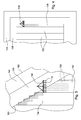
- Fig. 2 illustrates an irregularly shaped field 100.
- the first step is to define the field perimeter 102. This can be accomplished by driving along the perimeter in a first, perimeter headland pass 104 having the width of the planter 12. Planter 12 is shown schematically with the toolbar 14 and row units 12 shown as boxes.
- the first perimeter headland 104 can be driven with the planting machine operating to plant in the headland 104 or without operating the planter. Typically, the position sensor on the machine will be in the machine center, a half-width of the machine from the field perimeter.
- the perimeter can be defined by driving another vehicle, such as an all-terrain vehicle, along the perimeter with the necessary guidance system installed to record the vehicle path and with the spacing between the position sensor on the vehicle and the perimeter 102 known.
- a field perimeter definition recorded during an operation in a previous growing season can also be used.
- the perimeter headland area 104 is defined inside the perimeter 102 consisting of one width of the seeding machine.
- One or more additional headland areas 106 are defined inside the perimeter headland area 104 as desired.
- Each additional headland area has a width equal to the width of the machine 12.
- the headland area at the top and bottom of the field as shown in Fig. 2 is used for turning the machine as described below. Additionally, the headland area at the right side of the field will be used for turning the machine. However, the headland area at the left side is not used for turning and thus may be narrower than the other headland areas but still in multiples of the machine width.
- the remaining center area 108 of the field 100 is then defined. Beginning with a selected starting location such as the point 110, a path plan is determined for seeding the field beginning with the center area 108.
- the center area path plan consists of a series of back and forth passes 114 with turns 116 executed at the ends of the back and forth passes. The turns take place in the headland areas 106 and optionally 104.
- the path planning may be a mental step by the machine operator or may be done by a computer program that is part of the machine guidance system. When the machine reaches the border between the center area 108 and the headland area 106, the row units are turned off, to stop dispensing seed.
- Back and forth passes 120 at the right side of the field have borders 122 and 124 with the headland area which are inclined relative to the direction of machine travel in the back and forth passes.
- the row units are turned on and off, one at a time, or one section at time as those row units cross the border. This is shown by the broken lines trailing each row unit representing the seed rows. This is shown in the enlarged view of Fig. 3 .
- a row crop planter 130 is shown in the pass 120 crossing the border 124 between the center area and the headland area 106. Individual row units 10 are shut off as they cross the border.
- the seed rows are shown by the broken lines 132.
- Section control is shown with the back and forth pass 134.
- the dispensers for multiple plant rows are simultaneously controlled resulting in two or more rows starting or stopping together.
- the sections were turned off or on, producing a stair step pattern as multiple rows are shut off at a time.
- Fig. 4 shows another application where the final back and forth pass 136 is narrower than the width of planter 138.
- the last pass 136 When planting in the last pass 136, only those row units in the area of the pass 136 are operating. The row units in the area of the headland 106 are shut off.
- the headland area 106 is then planted.
- Headland area 106 is planted at a full machine width.
- Headland area 104 is also planted at a full width.
- Headland 104 may be planted last or may have been planted during the first step when the field perimeter is determined.
- the perimeter headland 104 may be planted using manual operation of the machine. This will be the case if the planting of the perimeter headland occurs during definition of the field perimeter.
- the field perimeter is defined from a machine operation in a previous growing season, there may be some variation in the actual field perimeter this season, due to erosion, etc. from the definition from the previous season.
- the perimeter headland 104 will preferably be planted by manual operation rather than automatic operation to be able to compensate for changes in the perimeter.
- the manual planting of the perimeter headland 104, whether performed first or last, may result in some overlap with the inner headland area 106 or with the center area 108 if there is only one headland area.
- the back and forth passes have been shown in Figs. 2-4 as being straight passes. Depending on the contours of the field, the passes may follow a curved path. In either case, the back and forth passes will generally be parallel with one another.
- An obstacle in the field can be dealt with as shown in reference to Fig. 5 .
- an obstacle 200 is in the center area of the field.
- the obstacle may be a wet area that can not be planted, a rock pile, a standard for overhead electric wires, etc.
- Four back and forth passes 202, 204, 206 and 208 are shown surrounding the obstacle.
- the pass 202 is worked first with the machine planting in rows shown by the lines 210. After turning, while working the subsequent pass 204 and planting the broken lines 212, the operator or machine control system steers the machine around the obstacle by turning into the preceding pass area 202, forming an incursion into pass 202.
- the control system knowing that pass area 202 has already been planted, will turn off the row units once they pass over the border 214 between the two pass areas 202 and 204. This avoids double planting but does not prevent disturbing the seed.
- the incursion into the preceding pass is recorded for future operations.
- the control system will know that there will be an incursion from the subsequent pass 204 into pass 202 and can turn off the row units during pass 202 in the incursion area. Then, when working pass 204 the row units can remain on and plant in the incursion area on the second time over that area.
- the operator may override the recording of the incursion if the obstacle will not likely be present during future operations.
- the obstacle is a wet area due to unusually high rainfall during the current planting season.
- the seed dispensers may remain on to double seed and ensure that the seed will be placed in the soil at the desired depth for proper emergence. The seed planted in the first pass will be disturbed and may no longer be at the proper depth.
- any fertilizer dispenser can be turned off during the incursion to prevent double fertilizer in the area as this can be detrimental to overall plant health.
- the machine makes an incursion into the subsequent pass 208 which is yet to be worked. Since the control system knows where the pass 208 is located, when the row units cross the border 216 into the subsequent pass 208, the row units are shut off. After turning, during working of pass 208, the row units remain on, and plant pass 208 with a full implement width, seeding the incursion area on the second pass over that area.
- machine is used broadly to mean a self-propelled input applicator or to a tractor and implement combination. Where an area of a field is covered twice during the application of an input, the method of the present invention controls the product dispensers to dispense product only the second time the area is covered.
Abstract
Description
- The present invention relates to a method of and a machine for applying inputs, such as seed or fertilizer, to an agricultural field and in particular to a method utilizing row or section control of the implement to avoid double seeding by turning off some of the product dispensers during the first pass over an area which is covered twice.
- When seeding a field or applying other inputs, a standard approach by producers is to make one to three headland passes around the field while applying seed and or fertilizer. Back and forth passes are then made in the center area of the field. By first planting in the headland passes, a line is formed in the field to indicate where to start and stop the back and forth passes in the center area while turning in the implement in the previously seeded headland area. A disadvantage of such a pattern is that while turning in the headland area, the tractor and implement will drive over the previously seeded headland area, causing compaction of the soil and disturbing the already planted seed. One way to avoid compaction of previous seeded soil is to seed the headline area last. This approach, however, requires the operator to estimate the point in the field where the back and forth passes start and stop. To ensure that the field is completely seeded, operators will tend to overlap into the inner headland area. When the headland area is subsequently planted, there will be an area that is double seeded and/or which may have double the amount of fertilizer or other chemical applied thereto.
- Recent advances in machine technology have enabled individual product dispensers of a planter to be selectively turned off to avoid dispensing seed where seed has already been planted or where it is desired not to plant seed. One technology for doing so is shown in
US 7 571 688 B1 , hereby incorporated by reference, where clutches are provided between the drive cable and seed meter to enable the each seed meter to be separately turned off. Other examples are shown inCA 2 650 340 A1 andUS patent application No. 12/481,254, filed June 9, 2009 - The individual row clutches or the section control can also be beneficial in planting an irregularly shaped field where all of the rows do not end at the same point where the implement passes into the headland area. As the implement approaches the end of the rows, individual row units or sections of row units can be shut off individually to avoid the double planting in the headland.
- Similar technology is available for use on sprayers to individually shut off the spray nozzles to avoid double spraying (
EP 1 183 929 A1EP 1 692 929 A1 - The present invention provides an improved method of applying an input to a field when using an implement having row or section control and when using an automated location and guidance system, enabled by GPS or other position technology, to avoid double application of inputs in areas covered more than once by the implement or machine. The present invention provides an application pattern and control in which first material is applied to a perimeter headland pass area. Then, material is applied to a center area, but leaving additional headland pass areas between the center area and the perimeter headland pass area free from material, since this additional headland pass areas are needed for turning the machine at the ends of the passes over the center area. Double application and damaging the soil with the material is avoided by turning off row units or sections of row units during the passes over the additional headland pass areas when working on the center area, leaving the actual application of inputs to a final pass over the additional headland area. The implement is controlled such that on the final pass over the additional headland area, the full width of the machine is used. This is particularly advantageous when seeding because the implement does not operate in soil that has already been seeded. Preferably, turning the machine during application of the material onto the center area is only performed on the additional headland pass areas but not on the perimeter headland pass area in order not to disturb the material that has already been placed there.
- An embodiment of the invention is shown in the drawings, in which:
-
Fig. 1 is a perspective view of a dispenser of a planting machine; -
Fig. 2 is a plan view of an agricultural field illustrating the method of the present invention; -
Fig. 3 is an enlargement of a portion of the field shown inFig. 2 illustrating the invention when used to plant point rows; -
Fig. 4 is a plan view illustrating another aspect of the method of the present invention when planting along the edge of a field; and -
Fig. 5 is a plan view of a portion of a field illustrating yet another aspect of the method of the present invention when planting around an obstacle in the field. - The method of the present invention is described below primarily in the context of a row crop planter. However, the method is applicable broadly to any input application machine such as but not limited to planter, air seeders, grain drills, fertilizer and chemical applicators, sprayers, etc. Referring to
Fig. 1 , arow unit 10 of arow crop planter 12 is shown. Theplanter 12 includes a transversely extendingtool bar 14 to which therow unit 10 is mounted. While a single row unit is show,multiple row units 10 are spaced along thetool bar 14, each applying seed in a row as the tool bar is moved across a field in an forward direction shown by thearrow 16. Theplanter 12 is connected to a tractor (not shown inFig. 1 ) in a conventional manner and the planter and tractor together constitute a machine for applying an input to an agricultural field. The planter or other input applicator could be self-propelled instead of an implement for attachment to a tractor. The tractor or self-propelled machine is equipped with a guidance system such as AutoTrac™ or iGuide™ available from John Deere to guide the machine along a path in the field. Such guidance systems use GPS or other positioning systems to locate the machine in the field and to guide its movement across the field. - The
row unit 10 includes aframe 20 that is coupled to amounting plate 22 by aparallel linkage 24. Theparallel linkage 24 allows the row unit to move up and down to a limited degree relative to thetoolbar 14. Seed is automatically directed to anauxiliary hopper 26 by a pneumatic seed on demand delivery system (not shown). Seed in theauxiliary hopper 26 is metered by aseed meter 28 and directed to a planting furrow by a seed tube (not shown) in a known manner. The planting furrow is formed by a doubledisc furrow opener 30.Depth gauging wheels 32 control the depth of penetration of theopener 30. The planting furrow with metered seed deposited therein by the seed tube is closed byclosing wheels 34. Theseed meter 28 is driven by a flexiblerotatable drive shaft 36 that drivessecond gear box 38. A ground driven common rotary drive, in the form of ahexagonal cross-section bar 40, provides a rotational input to theflexible drive shaft 36 through afirst gearbox 44. Aclutch 46 is provided at the coupling of thedrive shaft 36 to thesecond gear box 38. Theclutch 46 is selectively operated to disengage the drive to theseed meter 28 thereby stopping the operation of the seed meter and the dispensing of seed through the seed tube to the seeding furrow. Theclutches 46 may be individually controlled or two or more clutch assemblies on adjacent row units may be controlled together in what is known as "section control." - The
furrow opener 30 constitutes a ground engaging tool and remains engaged in the ground both when seed is being dispensed as well as when seed is not being dispensed by control of the clutches. Other seeding equipment such as air seeders and grain drills have ground engaging openers as do fertilizer and chemical applicators. These machines also have input meters and dispensers, such as seed tubes and/or chemical tubes. - The method and machine for applying an input to an agricultural field according to the present invention is shown and described in connection with
Fig. 2. Fig. 2 illustrates an irregularlyshaped field 100. The first step is to define thefield perimeter 102. This can be accomplished by driving along the perimeter in a first,perimeter headland pass 104 having the width of theplanter 12.Planter 12 is shown schematically with thetoolbar 14 androw units 12 shown as boxes. Thefirst perimeter headland 104 can be driven with the planting machine operating to plant in theheadland 104 or without operating the planter. Typically, the position sensor on the machine will be in the machine center, a half-width of the machine from the field perimeter. Alternatively, the perimeter can be defined by driving another vehicle, such as an all-terrain vehicle, along the perimeter with the necessary guidance system installed to record the vehicle path and with the spacing between the position sensor on the vehicle and theperimeter 102 known. A field perimeter definition recorded during an operation in a previous growing season can also be used. - The
perimeter headland area 104 is defined inside theperimeter 102 consisting of one width of the seeding machine. One or moreadditional headland areas 106 are defined inside theperimeter headland area 104 as desired. Each additional headland area has a width equal to the width of themachine 12. The headland area at the top and bottom of the field as shown inFig. 2 is used for turning the machine as described below. Additionally, the headland area at the right side of the field will be used for turning the machine. However, the headland area at the left side is not used for turning and thus may be narrower than the other headland areas but still in multiples of the machine width. - After determining the total headland area, the remaining
center area 108 of thefield 100 is then defined. Beginning with a selected starting location such as thepoint 110, a path plan is determined for seeding the field beginning with thecenter area 108. The center area path plan consists of a series of back and forth passes 114 withturns 116 executed at the ends of the back and forth passes. The turns take place in theheadland areas 106 and optionally 104. The path planning may be a mental step by the machine operator or may be done by a computer program that is part of the machine guidance system. When the machine reaches the border between thecenter area 108 and theheadland area 106, the row units are turned off, to stop dispensing seed. For those back and forth passes 114 which are perpendicular to the border of thecenter area 108, when the machine reaches the end of thepass 114, thetool bar 14 is raised, lifting the ground engaging tools from the ground. This also lifts the drive wheel for theshaft 40 from the ground, stopping the dispensing of seed from all row units at the same time. Preferably, turning the machine during application of the material onto thecenter area 108 is only performed on the additionalheadland pass areas 106 but not on the perimeterheadland pass area 104 in order not to disturb the material that has already been placed there. - Back and forth passes 120 at the right side of the field have
borders Fig. 3 . Arow crop planter 130 is shown in thepass 120 crossing theborder 124 between the center area and theheadland area 106.Individual row units 10 are shut off as they cross the border. The seed rows are shown by thebroken lines 132. - Section control is shown with the back and forth pass 134. The dispensers for multiple plant rows are simultaneously controlled resulting in two or more rows starting or stopping together. As the machine crossed the
border 124, the sections were turned off or on, producing a stair step pattern as multiple rows are shut off at a time. -
Fig. 4 shows another application where the final back and forth pass 136 is narrower than the width ofplanter 138. When planting in thelast pass 136, only those row units in the area of thepass 136 are operating. The row units in the area of theheadland 106 are shut off. - As a final step, the
headland area 106 is then planted.Headland area 106 is planted at a full machine width.Headland area 104 is also planted at a full width.Headland 104 may be planted last or may have been planted during the first step when the field perimeter is determined. Theperimeter headland 104 may be planted using manual operation of the machine. This will be the case if the planting of the perimeter headland occurs during definition of the field perimeter. Furthermore, if the field perimeter is defined from a machine operation in a previous growing season, there may be some variation in the actual field perimeter this season, due to erosion, etc. from the definition from the previous season. As a result, theperimeter headland 104 will preferably be planted by manual operation rather than automatic operation to be able to compensate for changes in the perimeter. The manual planting of theperimeter headland 104, whether performed first or last, may result in some overlap with theinner headland area 106 or with thecenter area 108 if there is only one headland area. - The back and forth passes have been shown in
Figs. 2-4 as being straight passes. Depending on the contours of the field, the passes may follow a curved path. In either case, the back and forth passes will generally be parallel with one another. - An obstacle in the field can be dealt with as shown in reference to
Fig. 5 . Here anobstacle 200 is in the center area of the field. The obstacle may be a wet area that can not be planted, a rock pile, a standard for overhead electric wires, etc. Four back and forth passes 202, 204, 206 and 208 are shown surrounding the obstacle. Thepass 202 is worked first with the machine planting in rows shown by thelines 210. After turning, while working thesubsequent pass 204 and planting the broken lines 212, the operator or machine control system steers the machine around the obstacle by turning into the precedingpass area 202, forming an incursion intopass 202. The control system, knowing thatpass area 202 has already been planted, will turn off the row units once they pass over theborder 214 between the twopass areas subsequent pass 204 intopass 202 and can turn off the row units duringpass 202 in the incursion area. Then, when workingpass 204 the row units can remain on and plant in the incursion area on the second time over that area. As an option, the operator may override the recording of the incursion if the obstacle will not likely be present during future operations. This may be the case if the obstacle is a wet area due to unusually high rainfall during the current planting season. Alternatively, during the first year planting operation, when the incursion occurs, the seed dispensers may remain on to double seed and ensure that the seed will be placed in the soil at the desired depth for proper emergence. The seed planted in the first pass will be disturbed and may no longer be at the proper depth. However, any fertilizer dispenser can be turned off during the incursion to prevent double fertilizer in the area as this can be detrimental to overall plant health. - On the following
pass 206, when the operator steers around the obstacle, the machine makes an incursion into thesubsequent pass 208 which is yet to be worked. Since the control system knows where thepass 208 is located, when the row units cross theborder 216 into thesubsequent pass 208, the row units are shut off. After turning, during working ofpass 208, the row units remain on, and plant pass 208 with a full implement width, seeding the incursion area on the second pass over that area. - In the claims that follow, the term "machine" is used broadly to mean a self-propelled input applicator or to a tractor and implement combination. Where an area of a field is covered twice during the application of an input, the method of the present invention controls the product dispensers to dispense product only the second time the area is covered.
Claims (13)
- A method of applying an input to an agricultural field (100) with a machine having multiple input dispensers arranged across a machine width to apply the input in rows as the machine is moved over the field (100), the machine further having control system to selectively stop one or more dispensers from dispensing the input while the remaining dispensers continue to dispense the input and the machine further having propulsion means and automated location and guidance means, the method comprising the steps of:defining a field perimeter (102);defining one or more headland pass areas (104, 106) each consisting of a full width of the machine to be made around the field with a perimeter headland pass area (104) adjacent the field perimeter (102) and additional headland pass areas (106) made inside the perimeter headland pass area (104);defining a remaining field center area (108) inside the headland pass areas (104, 106) to have the input applied in back and forth passes (114) of the machine;selecting a starting location (110) to begin applying the input;determining a path plan to apply the input with back and forth passes (114) in the center area (108) and turning the machine in the headland pass areas (104, 106) at the ends of the center area (108);applying the input first to the perimeter headland pass area (104) and executing the path plan on the center area (108) with turning off any of the dispensers while the dispensers are in the headland pass areas (104, 106) at the ends of the center area (108) and during any partial width pass along a side of the center area (108) where a portion of the dispensers are in the center area (108) and a portion of the dispensers are in the headland pass areas (104, 106); andthen applying the input to the additional headland pass areas (106) using the full width of the machine.
- The method as specified in claim 1 wherein the step of defining a field perimeter (102) is performed while making the first perimeter headland pass with the machine while applying the input and/ or by driving along the field perimeter (102) earlier in the current growing season and/or by driving along the field perimeter (102) during a previous growing season.
- The method as specified in claim 1 wherein the input is applied to the headland pass area (104, 106) during manual operation of the machine.
- The method as specified in claim 3 wherein as the input is applied to the headland pass area (104, 106), a new field perimeter is defined for future field operations.
- The method as specified in claim 3 wherein there is an incursion of a dispenser into the area of the adjacent headland pass as the input is applied to the headland pass area (104, 106) due to the actual field perimeter deviating from the defined field perimeter (102).
- The method as specified in claim 1 wherein during any deviation from parallel back and forth passes (114) in the center area (108) one or more dispensers move into a field area to be worked in a subsequent pass, the one or more dispensers are shut off while in the field area to be worked in a future pass.
- The method as specified in claim 1 wherein during any deviation from parallel back and forth passes (114) one or more dispensers move into field area of a preceding pass, data of the actual path is recorded and used in future field operations to shut off the dispensers while in the preceding pass when they are in the area of the incursion from a subsequent pass whereby in future field operations the input is applied in the area of the incursion only during the subsequent pass.
- The method as specified in claim 7 wherein an operator of the machine selectively overrides the data recording such that during future field operations the dispensers are not turned off during the preceding pass when they are in the area of the incursion from the subsequent pass.
- The method according to one of the preceding claims, wherein the machine applies seed to the agricultural field (100) and has multiple seed dispensers arranged across a machine width to apply the seed in rows as the machine is moved over the field (100), the machine further having a control system to selectively stop one or more dispensers from dispensing seed while the remaining dispensers continue to dispense seed and the machine further having propulsion means and automated location and guidance means.
- The method as defined in claim 9 wherein the machine has dispensers for seed and dispensers for fertilizer wherein fertilizer is only applied once to areas that are covered twice.
- The method as defined in any of the preceding claims wherein turning the machine during application of the material onto the center area (108) is only performed on the additional headland pass areas (106) but not on the perimeter headland pass area (104) in order not to disturb the material that has already been placed there.
- A machine for applying an input to an agricultural field (100) comprising:multiple input dispensers arranged across a machine width to apply the input in rows as the machine is moved over a field;a control system to selectively stop one or more dispensers from dispensing the input while the remaining dispensers continue to dispense the input; andan automated location and guidance system wherein the control system and the location and guidance system are adaptable to:define one or more headland pass areas (104, 106) each consisting of a full width of the machine to be made around the field with a first perimeter headland pass area (104) adjacent the field perimeter and additional headland pass areas (106) made inside the perimeter headland pass area (104);define a remaining field center area (108) inside the headland pass areas (104, 106) to have the input applied in back and forth passes of the machine;determine a path plan to apply the input in the perimeter headland pass area (104) and with back and forth passes (114) in the center area (108) and turning the machine in the headland pass areas (104, 106) at the ends of the center area (108);apply the input to the perimeter headland pass area (104) and then to execute the path plan to the center area (108) with turning off any of the dispensers while the dispensers are in the headland pass areas (104, 106) at the ends of the center area (108) and during any partial width pass along a side of the center area (108) where a portion of the dispensers are in the center area (108) and a portion of the dispensers are in the headland pass areas (104, 106); andthen apply the input to the additional headland pass area (106) using the full width of the machine.
- The machine as specified in claim 12 wherein control system and the location and guidance systems are adaptable to define the one or more headland pass areas (104, 106) while making the first perimeter headland pass with the machine while applying the input.
Applications Claiming Priority (1)
| Application Number | Priority Date | Filing Date | Title |
|---|---|---|---|
| US12/684,165 US8186288B2 (en) | 2010-01-08 | 2010-01-08 | Method of applying an input to an agricultural field |
Publications (2)
| Publication Number | Publication Date |
|---|---|
| EP2342963A1 true EP2342963A1 (en) | 2011-07-13 |
| EP2342963B1 EP2342963B1 (en) | 2012-11-21 |
Family
ID=43927637
Family Applications (1)
| Application Number | Title | Priority Date | Filing Date |
|---|---|---|---|
| EP10196203A Active EP2342963B1 (en) | 2010-01-08 | 2010-12-21 | Method of applying input to an agricultural field |
Country Status (9)
| Country | Link |
|---|---|
| US (1) | US8186288B2 (en) |
| EP (1) | EP2342963B1 (en) |
| AR (1) | AR079827A1 (en) |
| AU (1) | AU2011200027B2 (en) |
| BR (1) | BRPI1100092A2 (en) |
| CA (1) | CA2726966A1 (en) |
| ES (1) | ES2400142T3 (en) |
| RU (1) | RU2550077C2 (en) |
| UA (1) | UA105770C2 (en) |
Cited By (5)
| Publication number | Priority date | Publication date | Assignee | Title |
|---|---|---|---|---|
| EP2907369A1 (en) * | 2014-02-17 | 2015-08-19 | Amazonen-Werke H. Dreyer GmbH & Co. KG | Electronic machine management system for agricultural working machines |
| EP2910098A1 (en) * | 2014-02-20 | 2015-08-26 | CLAAS E-Systems KGaA mbH & Co KG | Agricultural machine and method for controlling a working device |
| DE102016207510A1 (en) | 2016-05-02 | 2017-11-02 | Deere & Company | Pneumatic seed drill |
| EP3251484A1 (en) * | 2016-06-03 | 2017-12-06 | Kverneland Group Kerteminde A/S | Method and device for operating an agricultural machine |
| EP3508046A1 (en) * | 2018-01-08 | 2019-07-10 | Amazonen-Werke H. Dreyer GmbH & Co. KG | Method for operating a distributor |
Families Citing this family (31)
| Publication number | Priority date | Publication date | Assignee | Title |
|---|---|---|---|---|
| US8850995B2 (en) | 2009-02-02 | 2014-10-07 | Deere & Company | Seeding machine with seed delivery system |
| US8868300B2 (en) * | 2009-08-28 | 2014-10-21 | Raven Industries, Inc. | Multi-variable rate agricultural product application system, device and method |
| US9031749B2 (en) * | 2011-06-10 | 2015-05-12 | Great Plaines Manfacturing, Inc. | Cultivation air seeder having sequentially operated tools |
| US9113591B2 (en) | 2012-06-18 | 2015-08-25 | Raven Industries, Inc. | Implement for adjustably metering an agricultural field input according to different frame sections |
| US9265188B2 (en) | 2012-12-07 | 2016-02-23 | Cnh Industrial Canada, Ltd. | Sectioned meter box assembly |
| US11160204B2 (en) | 2013-03-15 | 2021-11-02 | Raven Industries, Inc. | Localized product injection system for an agricultural sprayer |
| US9580256B2 (en) | 2013-03-15 | 2017-02-28 | Raven Industries, Inc. | Granular spreader section control |
| US9504212B2 (en) | 2013-03-15 | 2016-11-29 | Raven Industries, Inc. | Real time injection for agricultural sprayers |
| US9380773B2 (en) | 2013-03-21 | 2016-07-05 | Raven Industries, Inc. | Gear flow divider for agricultural product injection |
| US10173236B2 (en) | 2013-10-17 | 2019-01-08 | Raven Industries, Inc. | Nozzle control system and method |
| WO2015058091A1 (en) | 2013-10-17 | 2015-04-23 | Preheim John | Nozzle control system and method |
| US9591800B2 (en) | 2014-11-19 | 2017-03-14 | Cnh Industrial Canada, Ltd. | Agricultural implement metering system and method |
| US9609803B2 (en) | 2014-12-08 | 2017-04-04 | Cnh Industrial Canada, Ltd. | Agricultural product application in overlap areas |
| US10427179B2 (en) * | 2015-09-17 | 2019-10-01 | Cnh Industrial America Llc | Low flow metering system |
| US10386844B2 (en) | 2015-09-30 | 2019-08-20 | Deere & Company | System and method for using geo-fenced guidance lines |
| US10080325B2 (en) | 2015-10-27 | 2018-09-25 | Cnh Industrial America Llc | Predictive overlap control model |
| DE102016110090A1 (en) | 2016-06-01 | 2017-12-07 | Amazonen-Werke H. Dreyer Gmbh & Co. Kg | Method and device for controlling an agricultural distributor |
| CN106576523A (en) * | 2016-12-30 | 2017-04-26 | 深圳前海弘稼科技有限公司 | Planter control method and device and planter |
| WO2018129376A2 (en) | 2017-01-05 | 2018-07-12 | Raven Industries, Inc. | Configurable nozzle assembly and methods for same |
| US10882065B2 (en) | 2017-02-28 | 2021-01-05 | Deere & Company | Agricultural vehicle with adjustable row unit |
| US10694734B2 (en) | 2017-02-28 | 2020-06-30 | Deere & Company | Adjustable row unit and sprayer vehicle with adjustable row unit |
| US10575460B2 (en) | 2017-02-28 | 2020-03-03 | Deere & Company | Adjustable row unit and vehicle with adjustable row unit |
| US10799903B2 (en) * | 2017-02-28 | 2020-10-13 | Deere & Company | Adjustable row unit and vehicle with adjustable row unit |
| US10654063B2 (en) | 2017-02-28 | 2020-05-19 | Deere & Company | Adjustable row unit and agricultural vehicle with adjustable row unit |
| DE102018130248A1 (en) * | 2018-11-29 | 2020-06-04 | Amazonen-Werke H. Dreyer Gmbh & Co. Kg | Method of applying spreading material |
| BR112022006486A2 (en) | 2019-10-04 | 2022-08-23 | Raven Ind Inc | VALVE CONTROL SYSTEM AND METHOD |
| US11612160B2 (en) | 2019-10-04 | 2023-03-28 | Raven Industries, Inc. | Valve control system and method |
| BR102019023538A2 (en) * | 2019-11-08 | 2021-05-25 | Robert Bosch Limitada | input deposition method |
| US11778938B2 (en) | 2020-04-20 | 2023-10-10 | Deere & Company | Agricultural machine section control |
| FR3119508B1 (en) * | 2021-02-05 | 2023-12-29 | Kuhn S A S | Process for controlled sowing of an agricultural plot and system for its implementation |
| US20230189684A1 (en) * | 2021-12-21 | 2023-06-22 | Cnh Industrial America Llc | System and method for generating swath lines for a work vehicle |
Citations (7)
| Publication number | Priority date | Publication date | Assignee | Title |
|---|---|---|---|---|
| GB2342342A (en) * | 1998-09-08 | 2000-04-12 | John George Culley | A control device for boom-mounted agricultural equipment |
| FR2800232A1 (en) * | 1999-10-27 | 2001-05-04 | Renault Agriculture | Automatic guidance for agricultural machine, comprises global positioning system and calculator enabling machine to follow working trajectories from departure point and working area outline |
| US6236924B1 (en) * | 1999-06-21 | 2001-05-22 | Caterpillar Inc. | System and method for planning the operations of an agricultural machine in a field |
| EP1183929A2 (en) | 2000-08-14 | 2002-03-06 | Flexi-Coil Ltd. | Agricultural product application tracking and control |
| EP1692929A1 (en) | 2005-02-16 | 2006-08-23 | Amazonen-Werke H. Dreyer GmbH & Co. KG | Method for regulating and/or controlling agricultural centrifugal fertilizer spreaders |
| CA2650340A1 (en) | 2009-01-12 | 2009-04-22 | Straw Track Manufacturing Inc. | Seeding method avoiding overlap |
| US7571688B1 (en) | 2008-04-03 | 2009-08-11 | Deere & Company | Integrated clutches for a seeding machine |
Family Cites Families (10)
| Publication number | Priority date | Publication date | Assignee | Title |
|---|---|---|---|---|
| US6236907B1 (en) * | 1995-05-30 | 2001-05-22 | Ag-Chem Equipment Co., Inc. | System and method for creating agricultural decision and application maps for automated agricultural machines |
| US5878679A (en) * | 1997-08-18 | 1999-03-09 | Deere & Company | Product disconnect for metering device |
| US5913915A (en) * | 1997-09-30 | 1999-06-22 | Ag-Chem Equipment Company, Inc. | Multi-variable rate dispensing system for agricultural machines |
| US6216614B1 (en) * | 1999-04-28 | 2001-04-17 | Ag-Chem Equipment Co., Inc. | Boom dispensing point control system |
| CA2356575C (en) * | 2001-08-31 | 2004-07-13 | Bourgault Industries Ltd. | Zone control for agricultural product application |
| US7395769B2 (en) * | 2004-10-21 | 2008-07-08 | Jensen Layton W | Individual row rate control of farm implements to adjust the volume of crop inputs across wide implements in irregularly shaped or contour areas of chemical application, planting or seeding |
| US7661516B2 (en) * | 2006-01-05 | 2010-02-16 | Trimble Navigation Limited | Pneumatically actuated clutch |
| US7591226B2 (en) * | 2006-11-03 | 2009-09-22 | Cnh America Llc | Automatic path generation for tramlines |
| CA2622428C (en) * | 2007-09-21 | 2009-12-29 | Brian Dean | Sectional meter shut-off and agricultural implement having sectional meter shut-off |
| CA2635401C (en) | 2007-09-21 | 2009-11-24 | One Pass Implements Inc. | Air seeder/fertilizer apparatus having metering means and distribution manifold with selectively openable ports |
-
2010
- 2010-01-08 US US12/684,165 patent/US8186288B2/en active Active
- 2010-12-21 ES ES10196203T patent/ES2400142T3/en active Active
- 2010-12-21 EP EP10196203A patent/EP2342963B1/en active Active
- 2010-12-27 RU RU2010153871/13A patent/RU2550077C2/en not_active IP Right Cessation
-
2011
- 2011-01-03 AR ARP110100002A patent/AR079827A1/en active IP Right Grant
- 2011-01-04 AU AU2011200027A patent/AU2011200027B2/en active Active
- 2011-01-06 BR BRPI1100092-9A patent/BRPI1100092A2/en not_active IP Right Cessation
- 2011-01-06 UA UAA201100234A patent/UA105770C2/en unknown
- 2011-01-07 CA CA2726966A patent/CA2726966A1/en not_active Abandoned
Patent Citations (7)
| Publication number | Priority date | Publication date | Assignee | Title |
|---|---|---|---|---|
| GB2342342A (en) * | 1998-09-08 | 2000-04-12 | John George Culley | A control device for boom-mounted agricultural equipment |
| US6236924B1 (en) * | 1999-06-21 | 2001-05-22 | Caterpillar Inc. | System and method for planning the operations of an agricultural machine in a field |
| FR2800232A1 (en) * | 1999-10-27 | 2001-05-04 | Renault Agriculture | Automatic guidance for agricultural machine, comprises global positioning system and calculator enabling machine to follow working trajectories from departure point and working area outline |
| EP1183929A2 (en) | 2000-08-14 | 2002-03-06 | Flexi-Coil Ltd. | Agricultural product application tracking and control |
| EP1692929A1 (en) | 2005-02-16 | 2006-08-23 | Amazonen-Werke H. Dreyer GmbH & Co. KG | Method for regulating and/or controlling agricultural centrifugal fertilizer spreaders |
| US7571688B1 (en) | 2008-04-03 | 2009-08-11 | Deere & Company | Integrated clutches for a seeding machine |
| CA2650340A1 (en) | 2009-01-12 | 2009-04-22 | Straw Track Manufacturing Inc. | Seeding method avoiding overlap |
Cited By (8)
| Publication number | Priority date | Publication date | Assignee | Title |
|---|---|---|---|---|
| EP2907369A1 (en) * | 2014-02-17 | 2015-08-19 | Amazonen-Werke H. Dreyer GmbH & Co. KG | Electronic machine management system for agricultural working machines |
| EP2910098A1 (en) * | 2014-02-20 | 2015-08-26 | CLAAS E-Systems KGaA mbH & Co KG | Agricultural machine and method for controlling a working device |
| US9468140B2 (en) | 2014-02-20 | 2016-10-18 | Claas E-Systems Kgaa Mbh & Co Kg | Harvesting device |
| DE102016207510A1 (en) | 2016-05-02 | 2017-11-02 | Deere & Company | Pneumatic seed drill |
| EP3251484A1 (en) * | 2016-06-03 | 2017-12-06 | Kverneland Group Kerteminde A/S | Method and device for operating an agricultural machine |
| WO2017207604A1 (en) * | 2016-06-03 | 2017-12-07 | Kverneland Group Kerteminde A/S | Method and device for operating an agricultural machine |
| EP3251484B1 (en) | 2016-06-03 | 2018-09-26 | Kverneland Group Kerteminde A/S | Method and device for operating an agricultural machine |
| EP3508046A1 (en) * | 2018-01-08 | 2019-07-10 | Amazonen-Werke H. Dreyer GmbH & Co. KG | Method for operating a distributor |
Also Published As
| Publication number | Publication date |
|---|---|
| BRPI1100092A2 (en) | 2013-05-28 |
| RU2550077C2 (en) | 2015-05-10 |
| RU2010153871A (en) | 2012-07-10 |
| CA2726966A1 (en) | 2011-07-08 |
| EP2342963B1 (en) | 2012-11-21 |
| AU2011200027B2 (en) | 2016-04-28 |
| US8186288B2 (en) | 2012-05-29 |
| ES2400142T3 (en) | 2013-04-05 |
| AR079827A1 (en) | 2012-02-22 |
| US20110172811A1 (en) | 2011-07-14 |
| AU2011200027A1 (en) | 2011-07-28 |
| UA105770C2 (en) | 2014-06-25 |
Similar Documents
| Publication | Publication Date | Title |
|---|---|---|
| EP2342963B1 (en) | Method of applying input to an agricultural field | |
| EP3278645B1 (en) | Method for optimizing an operating parameter of a machine for the application of agricultural material to a field and corresponding machine | |
| AU2008301161B2 (en) | Sectional meter shut-off and agricultural implement having sectional meter shut-off | |
| AU2009337043B2 (en) | Seeding method avoiding overlap | |
| CA2704416C (en) | Depth adjustment of trailing arm furrow openers | |
| US8863676B2 (en) | Twin-row multiple variety planter and method of use | |
| US8307771B2 (en) | Row clutch device for planting implement | |
| US8326500B2 (en) | Row unit wheel turning monitor for an agricultural machine | |
| US20120132115A1 (en) | Sectional meter shut-off and agricultural implement having sectional meter shut-off | |
| CA2911624C (en) | Agricultural product application in overlap areas | |
| UA127013C2 (en) | Implements and application units having at least one application member for placement of applications with respect to agricultural plants of agricultural fields | |
| US8838346B1 (en) | Seeder | |
| JP2020113121A (en) | Farming system | |
| EP3763185A1 (en) | Agricultural implement and method for precision-controlling fertilizer metering units | |
| US20150216117A1 (en) | Method for producing marking strips using at least two seeders moving simultaneously in a field | |
| CA2685239C (en) | Sectional meter shut-off and agricultural implement having sectional meter shut-off | |
| US20160316613A1 (en) | Seed spacing system for a seed planter | |
| DE4020232A1 (en) | SEEDING MACHINE |
Legal Events
| Date | Code | Title | Description |
|---|---|---|---|
| PUAI | Public reference made under article 153(3) epc to a published international application that has entered the european phase |
Free format text: ORIGINAL CODE: 0009012 |
|
| AK | Designated contracting states |
Kind code of ref document: A1 Designated state(s): AL AT BE BG CH CY CZ DE DK EE ES FI FR GB GR HR HU IE IS IT LI LT LU LV MC MK MT NL NO PL PT RO RS SE SI SK SM TR |
|
| AX | Request for extension of the european patent |
Extension state: BA ME |
|
| 17P | Request for examination filed |
Effective date: 20120113 |
|
| GRAP | Despatch of communication of intention to grant a patent |
Free format text: ORIGINAL CODE: EPIDOSNIGR1 |
|
| RIC1 | Information provided on ipc code assigned before grant |
Ipc: A01B 79/00 20060101AFI20120625BHEP |
|
| GRAS | Grant fee paid |
Free format text: ORIGINAL CODE: EPIDOSNIGR3 |
|
| GRAA | (expected) grant |
Free format text: ORIGINAL CODE: 0009210 |
|
| AK | Designated contracting states |
Kind code of ref document: B1 Designated state(s): AL AT BE BG CH CY CZ DE DK EE ES FI FR GB GR HR HU IE IS IT LI LT LU LV MC MK MT NL NO PL PT RO RS SE SI SK SM TR |
|
| REG | Reference to a national code |
Ref country code: GB Ref legal event code: FG4D |
|
| REG | Reference to a national code |
Ref country code: CH Ref legal event code: EP |
|
| REG | Reference to a national code |
Ref country code: AT Ref legal event code: REF Ref document number: 584541 Country of ref document: AT Kind code of ref document: T Effective date: 20121215 |
|
| REG | Reference to a national code |
Ref country code: IE Ref legal event code: FG4D |
|
| REG | Reference to a national code |
Ref country code: DE Ref legal event code: R096 Ref document number: 602010003715 Country of ref document: DE Effective date: 20130117 |
|
| REG | Reference to a national code |
Ref country code: ES Ref legal event code: FG2A Ref document number: 2400142 Country of ref document: ES Kind code of ref document: T3 Effective date: 20130405 |
|
| REG | Reference to a national code |
Ref country code: NL Ref legal event code: VDEP Effective date: 20121121 |
|
| REG | Reference to a national code |
Ref country code: AT Ref legal event code: MK05 Ref document number: 584541 Country of ref document: AT Kind code of ref document: T Effective date: 20121121 |
|
| REG | Reference to a national code |
Ref country code: LT Ref legal event code: MG4D |
|
| PG25 | Lapsed in a contracting state [announced via postgrant information from national office to epo] |
Ref country code: LT Free format text: LAPSE BECAUSE OF FAILURE TO SUBMIT A TRANSLATION OF THE DESCRIPTION OR TO PAY THE FEE WITHIN THE PRESCRIBED TIME-LIMIT Effective date: 20121121 Ref country code: NO Free format text: LAPSE BECAUSE OF FAILURE TO SUBMIT A TRANSLATION OF THE DESCRIPTION OR TO PAY THE FEE WITHIN THE PRESCRIBED TIME-LIMIT Effective date: 20130221 Ref country code: HR Free format text: LAPSE BECAUSE OF FAILURE TO SUBMIT A TRANSLATION OF THE DESCRIPTION OR TO PAY THE FEE WITHIN THE PRESCRIBED TIME-LIMIT Effective date: 20121121 Ref country code: FI Free format text: LAPSE BECAUSE OF FAILURE TO SUBMIT A TRANSLATION OF THE DESCRIPTION OR TO PAY THE FEE WITHIN THE PRESCRIBED TIME-LIMIT Effective date: 20121121 Ref country code: SE Free format text: LAPSE BECAUSE OF FAILURE TO SUBMIT A TRANSLATION OF THE DESCRIPTION OR TO PAY THE FEE WITHIN THE PRESCRIBED TIME-LIMIT Effective date: 20121121 |
|
| PG25 | Lapsed in a contracting state [announced via postgrant information from national office to epo] |
Ref country code: BE Free format text: LAPSE BECAUSE OF FAILURE TO SUBMIT A TRANSLATION OF THE DESCRIPTION OR TO PAY THE FEE WITHIN THE PRESCRIBED TIME-LIMIT Effective date: 20121121 Ref country code: LV Free format text: LAPSE BECAUSE OF FAILURE TO SUBMIT A TRANSLATION OF THE DESCRIPTION OR TO PAY THE FEE WITHIN THE PRESCRIBED TIME-LIMIT Effective date: 20121121 Ref country code: PT Free format text: LAPSE BECAUSE OF FAILURE TO SUBMIT A TRANSLATION OF THE DESCRIPTION OR TO PAY THE FEE WITHIN THE PRESCRIBED TIME-LIMIT Effective date: 20130321 Ref country code: GR Free format text: LAPSE BECAUSE OF FAILURE TO SUBMIT A TRANSLATION OF THE DESCRIPTION OR TO PAY THE FEE WITHIN THE PRESCRIBED TIME-LIMIT Effective date: 20130222 Ref country code: PL Free format text: LAPSE BECAUSE OF FAILURE TO SUBMIT A TRANSLATION OF THE DESCRIPTION OR TO PAY THE FEE WITHIN THE PRESCRIBED TIME-LIMIT Effective date: 20121121 Ref country code: SI Free format text: LAPSE BECAUSE OF FAILURE TO SUBMIT A TRANSLATION OF THE DESCRIPTION OR TO PAY THE FEE WITHIN THE PRESCRIBED TIME-LIMIT Effective date: 20121121 |
|
| PG25 | Lapsed in a contracting state [announced via postgrant information from national office to epo] |
Ref country code: AT Free format text: LAPSE BECAUSE OF FAILURE TO SUBMIT A TRANSLATION OF THE DESCRIPTION OR TO PAY THE FEE WITHIN THE PRESCRIBED TIME-LIMIT Effective date: 20121121 |
|
| PG25 | Lapsed in a contracting state [announced via postgrant information from national office to epo] |
Ref country code: SK Free format text: LAPSE BECAUSE OF FAILURE TO SUBMIT A TRANSLATION OF THE DESCRIPTION OR TO PAY THE FEE WITHIN THE PRESCRIBED TIME-LIMIT Effective date: 20121121 Ref country code: EE Free format text: LAPSE BECAUSE OF FAILURE TO SUBMIT A TRANSLATION OF THE DESCRIPTION OR TO PAY THE FEE WITHIN THE PRESCRIBED TIME-LIMIT Effective date: 20121121 Ref country code: RS Free format text: LAPSE BECAUSE OF FAILURE TO SUBMIT A TRANSLATION OF THE DESCRIPTION OR TO PAY THE FEE WITHIN THE PRESCRIBED TIME-LIMIT Effective date: 20121121 Ref country code: MC Free format text: LAPSE BECAUSE OF NON-PAYMENT OF DUE FEES Effective date: 20121231 Ref country code: BG Free format text: LAPSE BECAUSE OF FAILURE TO SUBMIT A TRANSLATION OF THE DESCRIPTION OR TO PAY THE FEE WITHIN THE PRESCRIBED TIME-LIMIT Effective date: 20130221 Ref country code: DK Free format text: LAPSE BECAUSE OF FAILURE TO SUBMIT A TRANSLATION OF THE DESCRIPTION OR TO PAY THE FEE WITHIN THE PRESCRIBED TIME-LIMIT Effective date: 20121121 Ref country code: CZ Free format text: LAPSE BECAUSE OF FAILURE TO SUBMIT A TRANSLATION OF THE DESCRIPTION OR TO PAY THE FEE WITHIN THE PRESCRIBED TIME-LIMIT Effective date: 20121121 |
|
| PG25 | Lapsed in a contracting state [announced via postgrant information from national office to epo] |
Ref country code: RO Free format text: LAPSE BECAUSE OF FAILURE TO SUBMIT A TRANSLATION OF THE DESCRIPTION OR TO PAY THE FEE WITHIN THE PRESCRIBED TIME-LIMIT Effective date: 20121121 Ref country code: NL Free format text: LAPSE BECAUSE OF FAILURE TO SUBMIT A TRANSLATION OF THE DESCRIPTION OR TO PAY THE FEE WITHIN THE PRESCRIBED TIME-LIMIT Effective date: 20121121 |
|
| REG | Reference to a national code |
Ref country code: IE Ref legal event code: MM4A |
|
| PLBE | No opposition filed within time limit |
Free format text: ORIGINAL CODE: 0009261 |
|
| STAA | Information on the status of an ep patent application or granted ep patent |
Free format text: STATUS: NO OPPOSITION FILED WITHIN TIME LIMIT |
|
| REG | Reference to a national code |
Ref country code: HU Ref legal event code: AG4A Ref document number: E017011 Country of ref document: HU |
|
| 26N | No opposition filed |
Effective date: 20130822 |
|
| PG25 | Lapsed in a contracting state [announced via postgrant information from national office to epo] |
Ref country code: IE Free format text: LAPSE BECAUSE OF NON-PAYMENT OF DUE FEES Effective date: 20121221 |
|
| PG25 | Lapsed in a contracting state [announced via postgrant information from national office to epo] |
Ref country code: MT Free format text: LAPSE BECAUSE OF FAILURE TO SUBMIT A TRANSLATION OF THE DESCRIPTION OR TO PAY THE FEE WITHIN THE PRESCRIBED TIME-LIMIT Effective date: 20121121 Ref country code: AL Free format text: LAPSE BECAUSE OF FAILURE TO SUBMIT A TRANSLATION OF THE DESCRIPTION OR TO PAY THE FEE WITHIN THE PRESCRIBED TIME-LIMIT Effective date: 20121121 |
|
| REG | Reference to a national code |
Ref country code: DE Ref legal event code: R097 Ref document number: 602010003715 Country of ref document: DE Effective date: 20130822 |
|
| PG25 | Lapsed in a contracting state [announced via postgrant information from national office to epo] |
Ref country code: TR Free format text: LAPSE BECAUSE OF FAILURE TO SUBMIT A TRANSLATION OF THE DESCRIPTION OR TO PAY THE FEE WITHIN THE PRESCRIBED TIME-LIMIT Effective date: 20121121 |
|
| PG25 | Lapsed in a contracting state [announced via postgrant information from national office to epo] |
Ref country code: LU Free format text: LAPSE BECAUSE OF NON-PAYMENT OF DUE FEES Effective date: 20121221 Ref country code: CY Free format text: LAPSE BECAUSE OF FAILURE TO SUBMIT A TRANSLATION OF THE DESCRIPTION OR TO PAY THE FEE WITHIN THE PRESCRIBED TIME-LIMIT Effective date: 20121121 Ref country code: SM Free format text: LAPSE BECAUSE OF FAILURE TO SUBMIT A TRANSLATION OF THE DESCRIPTION OR TO PAY THE FEE WITHIN THE PRESCRIBED TIME-LIMIT Effective date: 20121121 |
|
| PG25 | Lapsed in a contracting state [announced via postgrant information from national office to epo] |
Ref country code: MK Free format text: LAPSE BECAUSE OF FAILURE TO SUBMIT A TRANSLATION OF THE DESCRIPTION OR TO PAY THE FEE WITHIN THE PRESCRIBED TIME-LIMIT Effective date: 20121121 |
|
| REG | Reference to a national code |
Ref country code: CH Ref legal event code: PL |
|
| PG25 | Lapsed in a contracting state [announced via postgrant information from national office to epo] |
Ref country code: CH Free format text: LAPSE BECAUSE OF NON-PAYMENT OF DUE FEES Effective date: 20141231 Ref country code: LI Free format text: LAPSE BECAUSE OF NON-PAYMENT OF DUE FEES Effective date: 20141231 |
|
| REG | Reference to a national code |
Ref country code: FR Ref legal event code: PLFP Year of fee payment: 6 |
|
| PGFP | Annual fee paid to national office [announced via postgrant information from national office to epo] |
Ref country code: GB Payment date: 20151229 Year of fee payment: 6 |
|
| PGFP | Annual fee paid to national office [announced via postgrant information from national office to epo] |
Ref country code: HU Payment date: 20151202 Year of fee payment: 6 |
|
| PG25 | Lapsed in a contracting state [announced via postgrant information from national office to epo] |
Ref country code: IS Free format text: LAPSE BECAUSE OF FAILURE TO SUBMIT A TRANSLATION OF THE DESCRIPTION OR TO PAY THE FEE WITHIN THE PRESCRIBED TIME-LIMIT Effective date: 20121121 |
|
| REG | Reference to a national code |
Ref country code: FR Ref legal event code: PLFP Year of fee payment: 7 |
|
| PG25 | Lapsed in a contracting state [announced via postgrant information from national office to epo] |
Ref country code: IT Free format text: LAPSE BECAUSE OF NON-PAYMENT OF DUE FEES Effective date: 20151221 |
|
| GBPC | Gb: european patent ceased through non-payment of renewal fee |
Effective date: 20161221 |
|
| PG25 | Lapsed in a contracting state [announced via postgrant information from national office to epo] |
Ref country code: IT Free format text: LAPSE BECAUSE OF NON-PAYMENT OF DUE FEES Effective date: 20151221 |
|
| PGFP | Annual fee paid to national office [announced via postgrant information from national office to epo] |
Ref country code: IT Payment date: 20151222 Year of fee payment: 6 |
|
| PGRI | Patent reinstated in contracting state [announced from national office to epo] |
Ref country code: IT Effective date: 20170710 |
|
| PG25 | Lapsed in a contracting state [announced via postgrant information from national office to epo] |
Ref country code: IT Free format text: LAPSE BECAUSE OF NON-PAYMENT OF DUE FEES Effective date: 20161221 |
|
| PGRI | Patent reinstated in contracting state [announced from national office to epo] |
Ref country code: IT Effective date: 20170710 |
|
| PG25 | Lapsed in a contracting state [announced via postgrant information from national office to epo] |
Ref country code: GB Free format text: LAPSE BECAUSE OF NON-PAYMENT OF DUE FEES Effective date: 20161221 Ref country code: HU Free format text: LAPSE BECAUSE OF NON-PAYMENT OF DUE FEES Effective date: 20161222 |
|
| REG | Reference to a national code |
Ref country code: FR Ref legal event code: PLFP Year of fee payment: 8 |
|
| PGFP | Annual fee paid to national office [announced via postgrant information from national office to epo] |
Ref country code: ES Payment date: 20230102 Year of fee payment: 13 |
|
| PGFP | Annual fee paid to national office [announced via postgrant information from national office to epo] |
Ref country code: FR Payment date: 20231227 Year of fee payment: 14 Ref country code: DE Payment date: 20231121 Year of fee payment: 14 |