EP2362330A2 - Device and method for detecting flat products - Google Patents
Device and method for detecting flat products Download PDFInfo
- Publication number
- EP2362330A2 EP2362330A2 EP11003404A EP11003404A EP2362330A2 EP 2362330 A2 EP2362330 A2 EP 2362330A2 EP 11003404 A EP11003404 A EP 11003404A EP 11003404 A EP11003404 A EP 11003404A EP 2362330 A2 EP2362330 A2 EP 2362330A2
- Authority
- EP
- European Patent Office
- Prior art keywords
- products
- detection
- beam profile
- electronic camera
- transport
- Prior art date
- Legal status (The legal status is an assumption and is not a legal conclusion. Google has not performed a legal analysis and makes no representation as to the accuracy of the status listed.)
- Granted
Links
- 238000000034 method Methods 0.000 title claims abstract description 22
- 238000001514 detection method Methods 0.000 claims abstract description 106
- 230000003287 optical effect Effects 0.000 claims abstract description 74
- 238000005286 illumination Methods 0.000 claims abstract description 60
- 238000011156 evaluation Methods 0.000 claims abstract description 22
- 238000007493 shaping process Methods 0.000 claims description 8
- 238000012544 monitoring process Methods 0.000 claims description 5
- 238000012545 processing Methods 0.000 claims description 4
- 230000015572 biosynthetic process Effects 0.000 claims description 3
- 238000011143 downstream manufacturing Methods 0.000 claims description 3
- 238000007599 discharging Methods 0.000 claims description 2
- 230000001960 triggered effect Effects 0.000 claims description 2
- 108010089746 wobe Proteins 0.000 claims 1
- 230000000284 resting effect Effects 0.000 description 3
- 230000001419 dependent effect Effects 0.000 description 2
- 230000004888 barrier function Effects 0.000 description 1
- 210000000078 claw Anatomy 0.000 description 1
- 238000004590 computer program Methods 0.000 description 1
- 238000012937 correction Methods 0.000 description 1
- 230000007547 defect Effects 0.000 description 1
- 238000012850 discrimination method Methods 0.000 description 1
- 238000000605 extraction Methods 0.000 description 1
- 229910052736 halogen Inorganic materials 0.000 description 1
- 150000002367 halogens Chemical class 0.000 description 1
- 238000002347 injection Methods 0.000 description 1
- 239000007924 injection Substances 0.000 description 1
- 230000005855 radiation Effects 0.000 description 1
- 239000002356 single layer Substances 0.000 description 1
- 230000003595 spectral effect Effects 0.000 description 1
Images
Classifications
-
- B—PERFORMING OPERATIONS; TRANSPORTING
- B65—CONVEYING; PACKING; STORING; HANDLING THIN OR FILAMENTARY MATERIAL
- B65H—HANDLING THIN OR FILAMENTARY MATERIAL, e.g. SHEETS, WEBS, CABLES
- B65H43/00—Use of control, checking, or safety devices, e.g. automatic devices comprising an element for sensing a variable
-
- B—PERFORMING OPERATIONS; TRANSPORTING
- B65—CONVEYING; PACKING; STORING; HANDLING THIN OR FILAMENTARY MATERIAL
- B65H—HANDLING THIN OR FILAMENTARY MATERIAL, e.g. SHEETS, WEBS, CABLES
- B65H29/00—Delivering or advancing articles from machines; Advancing articles to or into piles
- B65H29/003—Delivering or advancing articles from machines; Advancing articles to or into piles by grippers
-
- B—PERFORMING OPERATIONS; TRANSPORTING
- B65—CONVEYING; PACKING; STORING; HANDLING THIN OR FILAMENTARY MATERIAL
- B65H—HANDLING THIN OR FILAMENTARY MATERIAL, e.g. SHEETS, WEBS, CABLES
- B65H29/00—Delivering or advancing articles from machines; Advancing articles to or into piles
- B65H29/02—Delivering or advancing articles from machines; Advancing articles to or into piles by mechanical grippers engaging the leading edge only of the articles
- B65H29/04—Delivering or advancing articles from machines; Advancing articles to or into piles by mechanical grippers engaging the leading edge only of the articles the grippers being carried by endless chains or bands
-
- B—PERFORMING OPERATIONS; TRANSPORTING
- B65—CONVEYING; PACKING; STORING; HANDLING THIN OR FILAMENTARY MATERIAL
- B65H—HANDLING THIN OR FILAMENTARY MATERIAL, e.g. SHEETS, WEBS, CABLES
- B65H29/00—Delivering or advancing articles from machines; Advancing articles to or into piles
- B65H29/66—Advancing articles in overlapping streams
-
- B—PERFORMING OPERATIONS; TRANSPORTING
- B65—CONVEYING; PACKING; STORING; HANDLING THIN OR FILAMENTARY MATERIAL
- B65H—HANDLING THIN OR FILAMENTARY MATERIAL, e.g. SHEETS, WEBS, CABLES
- B65H43/00—Use of control, checking, or safety devices, e.g. automatic devices comprising an element for sensing a variable
- B65H43/08—Photoelectric devices
-
- G—PHYSICS
- G06—COMPUTING; CALCULATING OR COUNTING
- G06M—COUNTING MECHANISMS; COUNTING OF OBJECTS NOT OTHERWISE PROVIDED FOR
- G06M1/00—Design features of general application
- G06M1/08—Design features of general application for actuating the drive
- G06M1/10—Design features of general application for actuating the drive by electric or magnetic means
- G06M1/101—Design features of general application for actuating the drive by electric or magnetic means by electro-optical means
-
- G—PHYSICS
- G06—COMPUTING; CALCULATING OR COUNTING
- G06M—COUNTING MECHANISMS; COUNTING OF OBJECTS NOT OTHERWISE PROVIDED FOR
- G06M7/00—Counting of objects carried by a conveyor
-
- B—PERFORMING OPERATIONS; TRANSPORTING
- B65—CONVEYING; PACKING; STORING; HANDLING THIN OR FILAMENTARY MATERIAL
- B65H—HANDLING THIN OR FILAMENTARY MATERIAL, e.g. SHEETS, WEBS, CABLES
- B65H2301/00—Handling processes for sheets or webs
- B65H2301/40—Type of handling process
- B65H2301/42—Piling, depiling, handling piles
- B65H2301/422—Handling piles, sets or stacks of articles
- B65H2301/4224—Gripping piles, sets or stacks of articles
- B65H2301/42242—Gripping piles, sets or stacks of articles by acting on the outermost articles of the pile for clamping the pile
-
- B—PERFORMING OPERATIONS; TRANSPORTING
- B65—CONVEYING; PACKING; STORING; HANDLING THIN OR FILAMENTARY MATERIAL
- B65H—HANDLING THIN OR FILAMENTARY MATERIAL, e.g. SHEETS, WEBS, CABLES
- B65H2301/00—Handling processes for sheets or webs
- B65H2301/40—Type of handling process
- B65H2301/42—Piling, depiling, handling piles
- B65H2301/422—Handling piles, sets or stacks of articles
- B65H2301/4224—Gripping piles, sets or stacks of articles
- B65H2301/42244—Sets in which articles are offset to each other
-
- B—PERFORMING OPERATIONS; TRANSPORTING
- B65—CONVEYING; PACKING; STORING; HANDLING THIN OR FILAMENTARY MATERIAL
- B65H—HANDLING THIN OR FILAMENTARY MATERIAL, e.g. SHEETS, WEBS, CABLES
- B65H2511/00—Dimensions; Position; Numbers; Identification; Occurrences
- B65H2511/10—Size; Dimensions
- B65H2511/13—Thickness
-
- B—PERFORMING OPERATIONS; TRANSPORTING
- B65—CONVEYING; PACKING; STORING; HANDLING THIN OR FILAMENTARY MATERIAL
- B65H—HANDLING THIN OR FILAMENTARY MATERIAL, e.g. SHEETS, WEBS, CABLES
- B65H2511/00—Dimensions; Position; Numbers; Identification; Occurrences
- B65H2511/10—Size; Dimensions
- B65H2511/16—Irregularities, e.g. protuberances
-
- B—PERFORMING OPERATIONS; TRANSPORTING
- B65—CONVEYING; PACKING; STORING; HANDLING THIN OR FILAMENTARY MATERIAL
- B65H—HANDLING THIN OR FILAMENTARY MATERIAL, e.g. SHEETS, WEBS, CABLES
- B65H2511/00—Dimensions; Position; Numbers; Identification; Occurrences
- B65H2511/10—Size; Dimensions
- B65H2511/17—Deformation, e.g. stretching
-
- B—PERFORMING OPERATIONS; TRANSPORTING
- B65—CONVEYING; PACKING; STORING; HANDLING THIN OR FILAMENTARY MATERIAL
- B65H—HANDLING THIN OR FILAMENTARY MATERIAL, e.g. SHEETS, WEBS, CABLES
- B65H2511/00—Dimensions; Position; Numbers; Identification; Occurrences
- B65H2511/30—Numbers, e.g. of windings or rotations
-
- B—PERFORMING OPERATIONS; TRANSPORTING
- B65—CONVEYING; PACKING; STORING; HANDLING THIN OR FILAMENTARY MATERIAL
- B65H—HANDLING THIN OR FILAMENTARY MATERIAL, e.g. SHEETS, WEBS, CABLES
- B65H2513/00—Dynamic entities; Timing aspects
- B65H2513/40—Movement
- B65H2513/42—Route, path
-
- B—PERFORMING OPERATIONS; TRANSPORTING
- B65—CONVEYING; PACKING; STORING; HANDLING THIN OR FILAMENTARY MATERIAL
- B65H—HANDLING THIN OR FILAMENTARY MATERIAL, e.g. SHEETS, WEBS, CABLES
- B65H2553/00—Sensing or detecting means
- B65H2553/40—Sensing or detecting means using optical, e.g. photographic, elements
- B65H2553/41—Photoelectric detectors
- B65H2553/414—Photoelectric detectors involving receptor receiving light reflected by a reflecting surface and emitted by a separate emitter
-
- B—PERFORMING OPERATIONS; TRANSPORTING
- B65—CONVEYING; PACKING; STORING; HANDLING THIN OR FILAMENTARY MATERIAL
- B65H—HANDLING THIN OR FILAMENTARY MATERIAL, e.g. SHEETS, WEBS, CABLES
- B65H2553/00—Sensing or detecting means
- B65H2553/40—Sensing or detecting means using optical, e.g. photographic, elements
- B65H2553/42—Cameras
-
- B—PERFORMING OPERATIONS; TRANSPORTING
- B65—CONVEYING; PACKING; STORING; HANDLING THIN OR FILAMENTARY MATERIAL
- B65H—HANDLING THIN OR FILAMENTARY MATERIAL, e.g. SHEETS, WEBS, CABLES
- B65H2553/00—Sensing or detecting means
- B65H2553/40—Sensing or detecting means using optical, e.g. photographic, elements
- B65H2553/46—Illumination arrangement
-
- B—PERFORMING OPERATIONS; TRANSPORTING
- B65—CONVEYING; PACKING; STORING; HANDLING THIN OR FILAMENTARY MATERIAL
- B65H—HANDLING THIN OR FILAMENTARY MATERIAL, e.g. SHEETS, WEBS, CABLES
- B65H2557/00—Means for control not provided for in groups B65H2551/00 - B65H2555/00
- B65H2557/50—Use of particular electromagnetic waves, e.g. light, radiowaves or microwaves
- B65H2557/51—Laser
-
- B—PERFORMING OPERATIONS; TRANSPORTING
- B65—CONVEYING; PACKING; STORING; HANDLING THIN OR FILAMENTARY MATERIAL
- B65H—HANDLING THIN OR FILAMENTARY MATERIAL, e.g. SHEETS, WEBS, CABLES
- B65H2701/00—Handled material; Storage means
- B65H2701/10—Handled articles or webs
- B65H2701/19—Specific article or web
- B65H2701/1932—Signatures, folded printed matter, newspapers or parts thereof and books
-
- G—PHYSICS
- G06—COMPUTING; CALCULATING OR COUNTING
- G06M—COUNTING MECHANISMS; COUNTING OF OBJECTS NOT OTHERWISE PROVIDED FOR
- G06M2207/00—Indexing scheme relating to counting of objects carried by a conveyor
- G06M2207/02—Counting of generally flat and overlapped articles, e.g. cards, newspapers
Definitions
- the present invention relates to a device for detecting sheet-like products according to the preamble of claim 1 and a method for detecting sheet-like products according to claim 11.
- Devices for counting flat products are generally known technical aids to determine the number of flat products. Upon detection of a deviation between an expected number of sheets and the number determined by the meter, corresponding error correction processes may be initiated. In counting devices optical sensors are often used to detect the number of flat products contactlessly and quickly.
- Counting devices are for example in the EP-A-1 661 833 and the WO 2007/012206 disclosed.
- flat products transported in brackets are equipped with identification information which is subjected to an optical-electronic control when the flat products move past at a control point. Images of the identification information are registered by means of an image recording device. The captured images are processed electronically and, as a result of this processing, control signals are generated for downstream processing devices.
- planar products In the case of the known device, the planar products must additionally be provided with identification information which is then to be detected in an image acquisition process which is frequently dependent on ambient lighting. Completely flat adjacent products are not counted in this way or only with great effort.
- the object of the present invention is to provide an apparatus and a method for detecting sheet-like products, which makes it possible to detect defects in sheet-like products.
- the device according to the invention for detecting sheet-like products, in particular printed products has a light source, an optical sensor and an evaluation unit connected to the optical sensor.
- the light source in a preferred embodiment, a laser, has a beam shaping optics, for example in the form of optical lenses, in particular of cylindrical lenses, of apertures or diffractive optical elements, through which the emitted light, a predetermined illumination beam profile "imprinted" is.
- a predetermined illumination beam profile "imprinted" Within the illumination beam profile objects are irradiated with light.
- the light source can be assigned via the beam shaping optical system an optical axis, which is based on the light source extends in a straight line in the room. For the purposes of this application, this optical axis simultaneously forms a central beam axis of the illumination beam profile and is also referred to below as an illumination beam axis.
- the optical sensor in a preferred embodiment for example an electronic camera with a plurality of photosensitive elements, is equipped with a detection optical system for forming a detection beam profile.
- detection optics for example, a camera lens is used.
- the detection beam profile includes all the locations from which the optical sensor can detect light.
- the detection beam profile of the optical sensor is composed of the individual detection beam profiles associated with each individual photosensitive element.
- the detection beam profile of the optical sensor could be visualized by replacing the photosensitive elements with small light sources.
- an optical axis can also be assigned to the optical sensor via the detection optics. For the purposes of this application, this optical axis simultaneously forms a central beam axis of the detection beam profile and is also referred to below as a detection beam axis.
- the illumination beam profile and the detection beam profile are aligned with an angle offset from one another such that they overlap in a detection area.
- the illumination beam axis and the detection beam axis are even in one plane.
- To count the Flat products must be at least a portion of the surface profile of the sheet products in the detection area.
- This section is according to the invention at least partially limited by the illumination beam profile and detectable by means of the optical sensor.
- the optical sensor may generate a detection signal with information about the detected portion of the surface profile.
- the detection signal is forwarded to a downstream evaluation unit.
- the evaluation unit preferably a computer, can use the detection signal to determine the number of areal products which were located in the detection area at the time of detection.
- the device for detecting sheet-like products is assigned a transport device.
- the flat products which are moved through the detection area along a transport direction by means of the transport device are preferably continuously counted in order, for example, to check their completeness.
- the illumination beam axis is preferably aligned inclined relative to the surface normal of, for example, resting on a conveyor belt or transported by means of brackets or grippers flat products.
- the illumination beam profile in the detection area is preferably formed by means of the beam shaping optics as a substantially rectilinear region, in particular as a so-called illumination line, which illuminates the section of the surface profile of the planar products in a defined manner.
- the illumination line extends substantially parallel to Transport direction.
- a camera as an optical sensor.
- the detection beam profile is formed by the detection optics such that an image of the light line projected onto the surface of the planar products by the light source is generated on the photosensitive elements of the camera.
- an image recorded by the camera is projected from the illumination line projected onto this uneven "projection surface” whose bends and heels reflect.
- This image information is forwarded in the detection signal to an electrically connected computer.
- a computer-executable image processing program can then determine from the image of the projected illumination line on the basis of the curvatures and paragraphs the number of planar products that have been in the detection area. So that the image information is influenced as little as possible by movement artefacts due to the transport of the sheet-like products during image acquisition, the recording or detection time is short compared to the time within which a flat product has moved by the amount of its thickness.
- the imperfections of the area in the detection area sheet products is determined solely from the detected surface profile of the sheet products. It is not necessary to attach identification information to the sheet products. Due to the relative to the ambient light comparatively high intensity of the light generated by the light source in the illumination beam profile, in particular within the illumination line in the detection area, there is sufficient contrast in the image recordings, so that a reliable identification of the illuminated surface profile is guaranteed.
- the optical sensor may be provided with corresponding filter elements to further reduce the interference of ambient light.
- the device according to the invention and the method according to the invention are, in addition to the recognition of sheet-like products, also suitable for counting the sheet-like products.
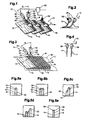
- FIG Fig. 1 A particularly preferred embodiment of the device according to the invention for counting and detecting sheet-like products (also referred to below as counting device) 10 with a transport device 12 assigned to it is shown in FIG Fig. 1 shown schematically.
- the light source 16 preferably lasers, in particular laser diodes or gas lasers, LEDs, but also classical radiation sources, such as incandescent or halogen lamps, can be used.
- the light source 16 is equipped with beam shaping optics 22 which provide a predetermined illumination beam profile 24 and define an optical axis of the light source 16.
- the illumination beam profile 24 of the light source 16 arranged laterally relative to a transport direction T along which the planar products 14 are transported has a cross section (also beam cross section) with a substantially at least partially rectilinear boundary, substantially line-like, preferably substantially rectilinear shape.
- the beam cross section is measured at right angles to the optical axis of the light source 16, hereinafter also referred to as the illumination beam axis 26.
- the line-like, preferably straight beam cross-section is also referred to as the illumination line.
- the illumination beam profile 24 with its line-like beam cross-section extends substantially in one plane.
- Elongated, essentially line-like beam cross-sections can be produced with known beam-shaping optics 22, which are equipped, for example, with cylindrical lenses, diaphragms or diffractive elements.
- the illumination beam profile 24 preferably has a higher light intensity than the ambient light, at least in a detection area defined below.
- the light source 16 preferably provides substantially monochromatic light, such as that produced by lasers, single color LEDs, or classic light sources equipped with filters. In this way, it is possible to distinguish the light generated by the light source 16 and scattered by the planar products 14 and detected by the optical sensor 18 from the ambient light, both because of its intensity and its spectral range, and thus reliable detection and counting of the sheet-like products 14 to ensure.
- an optical sensor 18 in the described embodiments of the inventive counting device 10 is an electronic camera with a plurality of photosensitive elements, such as a CCD camera, used.
- the optical sensor 18 is equipped with a detection lens 28 in the form of a camera lens, which provides a detection beam profile 30 and defines an optical axis of the optical sensor 18.
- the optical axis of the optical sensor 18 will hereinafter be referred to as the detection beam axis 32.
- the optical sensor 18 is arranged above the sheet-like products 14, so that an image of the light line projected onto the flat products 14 on the photosensitive elements of the optical sensor 18 is generated by means of the detection optics 28.
- the illumination beam profile 24 of the light source 16 and the detection beam profile 30 of the optical sensor 18 are aligned with angular offset from each other so that they overlap in a detection area in which there is at least a portion 33 of a surface profile of the sheet products 14 for counting.
- the located in the detection area and thus illuminated portion 33 of the surface profile is at least partially limited by the predetermined illumination beam profile 24.
- a scattering angle ⁇ included by the illumination beam axis 26 and the detection beam axis 32 is preferably between 10 ° and less than 180 °, more preferably between 30 ° and 45 °.
- the light source 16 may be arranged laterally with respect to the sheet-like products 14, that the longitudinal axis of the illumination line is aligned substantially parallel to the transport direction T.
- the illumination line preferably extends over an edge region of the sheet-like products 14 folded flat products 14 preferably over the collar 34th
- the optical sensor 18 can be arranged both above and laterally from the flat products 14.
- the illustrated positions of light source 16 and optical sensor 18 are also interchangeable.
- the detection beam axis 32 or the illumination beam axis 26 is preferably aligned inclined to the surface normal of the flat products 14 and at right angles to the transport direction T.
- the basic principle of the counting device 10 is that the known in their form, substantially rectilinear illumination line is projected onto an uneven by the thickness and / or arrangement of the sheet 14 products section 33 of the surface profile of the sheet products 14 and at a staggered detection, the height changes the surface profile of the sheet-like products as curvatures and paragraphs in the capture of the optical sensor 18 image of the illumination line can be detected.
- the illuminated portion 33 of the surface profile of the flat products 14 detected by the optical sensor 18 is in the considered embodiment, in which a camera is used as an optical sensor 18, as an image recording.
- the image information is forwarded by means of a detection signal via an electrical connection to the evaluation unit 20, for example a computer.
- the relevant information about the detected section 33 of the surface profile is extracted from the detection signal by means of a suitable computer program, in particular by means of an image processing program, and associated curvatures, edges and paragraphs are assigned to a specific number of planar products 14.
- a suitable computer program in particular by means of an image processing program, and associated curvatures, edges and paragraphs are assigned to a specific number of planar products 14.
- disturbing additional information still present in the images for example signs and images visible on the surface of the planar products 14 due to the ambient light, can be filtered out by known discrimination methods.
- a scanned by means of the inventive counting device surface profile is in the Fig. 1 and 3 by dashed lines, which are provided with the reference numeral A shown.
- the sheet products 14 are in Fig. 1 transported by means belonging to the counting device 10 transport 36 in the form of brackets.
- two planar products 14 are each held by a respective transporting means 36 in such a way that a flat product 14 leading in the transport direction T extends further into a clamping mouth of the transporting means 36, as a trailing further flat product 14 partially resting on the leading flat product 14.
- the respective transport means 36 themselves can, as also in Fig. 1 shown, by a further sensor 38, for example in the form of a light barrier, to be detected.
- a further sensor 38 for example in the form of a light barrier
- the number of areal products 14 detected at a specific time can now be assigned to a specific transport means 36.
- a predetermined target number of flat products which should be held by a transport means 36 is now determined whether errors in the placement of the transport means 36 or the transport have occurred, so that, for example, a corresponding control signal can be triggered to a downstream processing device ,
- the used for the assignment further sensor 38 is also in Fig. 2 shown. It can be seen in the transport direction T, both before the counting device 10 and after the counting device 10 may be arranged. At the in Fig. 2 shown embodiment of the transport device 12 are each two flat products 14 completely superimposed held by grippers trained transport 36.
- Fig. 3 is a further embodiment of a transport device 12 with a conveyor belt shown as transport 36.
- the sheet-like products 14 are transported with their collar 34 in the transport direction T leading in an imbricated formation on the transport means 36 resting through the detection area of the counting device 10.
- the surface profile A of the planar products 14 scanned by the counting device 10 is represented by a dashed line.
- the optical sensor 18 In an arrangement of the optical sensor 18 such that its detection beam axis 32 is aligned substantially along the longitudinal axis of the collar 34 of the sheet products 14, which could be in the FIGS. 5a to 5e be shown abstracted image taken.
- the illumination beam axis 26 of the light source 16 is directed from the top to the camera-side free end region of the collar 34 and advantageously extends at least nearly parallel to product pages 40 of the sheet 14.
- the illumination beam axis 26 and the detection beam axis 32 span here a plane that is in the Substantially perpendicular to the transport direction T extends.
- FIGS. 5a to 5e In addition to the illuminated by the illumination line sections 33 of the surface profiles, which are shown as dashed lines, for clarity, the side views of each sampled planar products 14 in the abstracted images are shown. On the basis of these exemplary abstracted image recordings, it is shown that planar products 14 transported in a suspended manner by means of grippers or clamps (individually Fig. 5a ), in pairs ( Fig. 5b, 5c and 5e ) or in a multiple arrangement, for example, three ( Fig. 5d ), transported and counted.
- a detection and counting is shown both with flat products 14 (FIG. Fig. 5c and Fig. 5d ), as well as in completely adjacent flat products 14 possible.
- the optical quality of the image recordings and thus the reliability of the counting that the camera acting as the optical sensor 18 records image recordings within a time that is shorter , is preferably much shorter than the time within which a sheet product 14 moves by the amount of its thickness in the detection area.
- the reliability of the counting can be increased if, as previously mentioned, the light intensity of the light source 16 is increased relative to the ambient light or a filter tuned to the wavelength of the light emitted by the light source 16 is used in the optical sensor 18 , In addition, it is by an increase in the angle ⁇ between the illumination beam axis 26 and the detection beam axis 32, it is possible to increase the curvatures, edges and heights in the images of the illuminated surface portions 33.
- the counting device 10 according to the invention and the method according to the invention for counting sheet-like products 14 make it possible to count surface products 14 that are suitable and reliable for a variety of transport formats of sheet-like products 14 with moderate equipment complexity.
- the sheet-like products 14 can be transported during detection and counting be, with the amount of transport speed is limited by the shortest possible recording time of the optical sensor 18, in which, despite resulting from the transport movement artifacts in the image recordings a reliable count possible.
- both the illumination beam profile 24 and the detection beam profile 30 can be adapted to the specific needs. It is thus possible to project a plurality of illumination lines or also time-varying patterns of illumination lines onto the surface of the planar products 14 and to detect them by means of the optical sensor 18. It is important that the located in the detection area surface portion 33 of the sheet products 14 is at least partially limited by the predetermined illumination beam profile 24.
- the device for detecting, and also counting, flat products 14, in particular printed products has a light source 16, an optical sensor 18 with detection optics 28 for forming a detection beam profile 30 and an evaluation unit 20 connected to the optical sensor 18, characterized in that in that the light source 16 is equipped with beam shaping optics 22 for shaping an illumination beam profile 24 which overlaps with the detection beam profile 30 of the optical sensor 18 in a detection area, and an angle-offset orientation of the illumination beam profile 24 relative to the detection beam profile 30 means that a section 33 of a surface profile of the planar products 14 located in the detection area and bounded at least partially by the illumination beam profile 24 can be detected by means of the optical sensor 18 and from one of the optical sensor 18 generated detection signal containing information about the detected portion 33 of the surface profile, the number of sheet products 14 in the detection area by means of the evaluation unit 20 can be determined.
- the cross-section of the illumination beam profile 24 in the detection area, measured at right angles to the optical axis 32 of the light source 16, is substantially at least partially rectilinear, preferably substantially line-like, particularly preferably substantially rectilinearly shaped to form a line of illumination.
- the optical axes 26, 32 of the light source 16 and of the optical sensor 18 enclose an angle between about 10 ° and less than 180 °, preferably between 30 ° and 45 °.
- optical axes 26, 32 of the light source 16 and / or the optical sensor 18 are inclined to the surface normal of the sheet products 14 aligned.
- planar products 14 are transported by means of an associated transport device 12 along a transport direction T, wherein the optical axis 32 of the optical Sensor 18 is oriented substantially perpendicular to the transport direction T and the longitudinal axis of a cross section of the illumination beam profile 24 in the detection region is substantially parallel to the transport direction T.
- a further sensor 38 which, when a transport means 36 of the transport device 12 passes through a monitoring area of the further sensor 38, generates a trigger signal, so that the number of areal products 14 determined at a particular time can be assigned to the respective transport means 36 ,
- the optical sensor 18 is a camera, preferably an electronic camera, particularly preferably a CCD or CMOS camera, which detects image recordings within a recording time which is shorter, preferably much shorter than the time within which a sheet product 14 is moved by the amount of its thickness in the detection area.
- the light intensity in the illumination beam profile 24 of the light source 16 in the detection area is greater than the light intensity of the ambient light and that the light source 16 preferably provides substantially monochromatic light and is particularly preferably designed as a laser.
- the invention relates to a method for detecting, and also counting, flat products 14, in particular printed products, using a device 10 for detecting sheet-like products 14 according to one of the preceding embodiments, wherein by a angularly offset alignment of the illumination beam profile 24 with respect to the detection beam profile 30, a section 33 of a surface profile of the planar products 14 which is located in the detection area and is limited at least partially by the illumination beam profile 24, is detected by means of the optical sensor 18 and wherein a detection signal generated by the optical sensor 18, contains information about the detected portion 33 of the surface profile, the number of sheet products 14 in the detection area is determined by means connected to the optical sensor 18 evaluation unit 20.
- an edge region of one of the sheet-like products 14 is located in the detection region during the detection.
- the flat products 14 are individually, partially overlapping or completely adjacent to one another in a scale formation relative to the device 10 along a transport direction T with the aid of transport means 36 of a transport device 12 associated with the device 10, in particular with the aid of clamps, grippers or a conveyor belt, transported in the detection area.
- a trigger signal when a passage from one of the transport means 36 through a monitoring area of another sensor 38, a trigger signal can be generated, so that the determined at a specific time number of sheet products 14 can be assigned to exactly one transport 36.
- the number of planar products 14 is determined from recordings recorded by the optical sensor 18 by means of an image processing program which is carried out in the evaluation unit 20.
Abstract
Description
Die vorliegende Erfindung betrifft eine Vorrichtung zum Erkennen von flächigen Produkten gemäss dem Oberbegriff des Anspruchs 1 und ein Verfahren zum Erkennen von flächigen Produkten gemäss dem Anspruch 11.The present invention relates to a device for detecting sheet-like products according to the preamble of claim 1 and a method for detecting sheet-like products according to claim 11.
Vorrichtungen zum Zählen von flächigen Produkten (kurz auch Zählvorrichtungen) sind allgemein bekannte technische Hilfsmittel, um die Anzahl flächiger Produkte zu ermitteln. Bei Feststellung einer Abweichung zwischen einer erwarteten Anzahl von flächigen Produkten und der von der Zählvorrichtung bestimmten Anzahl können entsprechende Fehlerkorrekturprozesse ausgelöst werden. In Zählvorrichtungen werden häufig optische Sensoren eingesetzt, um die Anzahl von flächigen Produkten berührungslos und schnell zu erfassen.Devices for counting flat products (in short also counting devices) are generally known technical aids to determine the number of flat products. Upon detection of a deviation between an expected number of sheets and the number determined by the meter, corresponding error correction processes may be initiated. In counting devices optical sensors are often used to detect the number of flat products contactlessly and quickly.
Zählvorrichtungen sind beispielsweise in der
Bei der bekannten Vorrichtung müssen die flächigen Produkte zusätzlich mit Identifikationsinformationen ausgestattet werden, die dann in einem häufig von der Umgebungsbeleuchtung abhängigen Bildaufnahmeprozess zu detektieren sind. Vollständig flächig aneinander anliegende Produkte sind auf diese Weise nicht oder nur mit grösserem Aufwand zählbar.In the case of the known device, the planar products must additionally be provided with identification information which is then to be detected in an image acquisition process which is frequently dependent on ambient lighting. Completely flat adjacent products are not counted in this way or only with great effort.
Aufgabe der vorliegenden Erfindung ist es, eine Vorrichtung und ein Verfahren zum Erkennen von flächigen Produkten bereitzustellen, die bzw. das es erlaubt, Fehlstellen in flächigen Produkten zu erkennen.The object of the present invention is to provide an apparatus and a method for detecting sheet-like products, which makes it possible to detect defects in sheet-like products.
Diese Aufgabe wird durch eine Vorrichtung zum Erkennen von flächigen Produkten gemäss Anspruch 1 und ein Verfahren zum Erkennen von flächigen Produkten gemäss Anspruch 11 gelöst. Besonders bevorzugte Ausführungsformen sind mit den in den abhängigen Ansprüchen aufgeführte Merkmalen ausgestattet.This object is achieved by a device for detecting sheet-like products according to claim 1 and a method for detecting sheet-like products according to claim 11. Particularly preferred embodiments are equipped with the features listed in the dependent claims.
Die erfindungsgemässe Vorrichtung zum Erkennen von flächigen Produkten, insbesondere von Druckereiprodukten, weist eine Lichtquelle, einen optischen Sensor und eine mit dem optischen Sensor verbundenen Auswerteeinheit auf. Die Lichtquelle, in einer bevorzugten Ausführungsform ein Laser, verfügt über eine Strahlformungsoptik, beispielsweise in Form von optischen Linsen, insbesondere von Zylinderlinsen, von Blenden oder diffraktiven optischen Elementen, durch welche dem ausgesendeten Licht ein vorbestimmtes Beleuchtungsstrahlprofil "aufgeprägt" wird. Innerhalb des Beleuchtungsstrahlprofils befindliche Objekte werden mit Licht bestrahlt. Der Lichtquelle kann über die Strahlformungsoptik eine optische Achse zugeordnet werden, die sich ausgehend von der Lichtquelle geradlinig im Raum erstreckt. Diese optische Achse bildet im Sinne dieser Anmeldung gleichzeitig eine zentrale Strahlachse des Beleuchtungsstrahlprofils und wird im Weiteren auch als Beleuchtungsstrahlachse bezeichnet.The device according to the invention for detecting sheet-like products, in particular printed products, has a light source, an optical sensor and an evaluation unit connected to the optical sensor. The light source, in a preferred embodiment, a laser, has a beam shaping optics, for example in the form of optical lenses, in particular of cylindrical lenses, of apertures or diffractive optical elements, through which the emitted light, a predetermined illumination beam profile "imprinted" is. Within the illumination beam profile objects are irradiated with light. The light source can be assigned via the beam shaping optical system an optical axis, which is based on the light source extends in a straight line in the room. For the purposes of this application, this optical axis simultaneously forms a central beam axis of the illumination beam profile and is also referred to below as an illumination beam axis.
Der optische Sensor, in einer bevorzugten Ausführungsform beispielsweise eine elektronische Kamera mit einer Mehrzahl von lichtempfindlichen Elementen, ist mit einer Detektionsoptik zur Formung eines Detektionsstrahlprofils ausgestattet. Als Detektionsoptik wird beispielsweise ein Kameraobjektiv eingesetzt. Das Detektionsstrahlprofil umfasst all die Orte, von denen der optische Sensor Licht detektieren kann. Bei Verwendung eines optischen Sensors mit mehreren lichtempfindlichen Elementen, wie bei der bereits erwähnten Kamera, setzt sich das Detektionsstrahlprofil des optischen Sensors aus den jedem einzelnen lichtempfindlichen Element zugeordneten einzelnen Detektionsstrahlprofilen zusammen. Das Detektionsstrahlprofil des optischen Sensors könnte beispielsweise sichtbar gemacht werden, in dem die lichtempfindlichen Elemente durch kleine Lichtquellen ersetzt werden würden. In Analogie zur Lichtquelle kann auch dem optischen Sensor über die Detektionsoptik eine optische Achse zugeordnet werden. Diese optische Achse bildet im Sinne dieser Anmeldung gleichzeitig eine zentrale Strahlachse des Detektionsstrahlprofils und wird im Weiteren auch als Detektionsstrahlachse bezeichnet.The optical sensor, in a preferred embodiment for example an electronic camera with a plurality of photosensitive elements, is equipped with a detection optical system for forming a detection beam profile. As detection optics, for example, a camera lens is used. The detection beam profile includes all the locations from which the optical sensor can detect light. When using an optical sensor having a plurality of photosensitive elements, as in the aforementioned camera, the detection beam profile of the optical sensor is composed of the individual detection beam profiles associated with each individual photosensitive element. For example, the detection beam profile of the optical sensor could be visualized by replacing the photosensitive elements with small light sources. In analogy to the light source, an optical axis can also be assigned to the optical sensor via the detection optics. For the purposes of this application, this optical axis simultaneously forms a central beam axis of the detection beam profile and is also referred to below as a detection beam axis.
Das Beleuchtungsstrahlprofil und das Detektionsstrahlprofil sind erfindungsgemäss derart winkelversetzt zueinander ausgerichtet, dass sie in einem Detektionsbereich überlappen. In einer bevorzugten Ausführungsform liegen die Beleuchtungsstrahlachse und die Detektionsstrahlachse sogar in einer Ebene. Zum Zählen der flächigen Produkte muss sich wenigstens ein Abschnitt des Oberflächenprofils der flächigen Produkte im Detektionsbereich befinden. Dieser Abschnitt ist erfindungsgemäss wenigstens teilweise durch das Beleuchtungsstrahlprofil begrenzt und mittels des optischen Sensors detektierbar. Der optische Sensor kann ein Detektionssignal mit Informationen über den detektierten Abschnitt des Oberflächenprofils erzeugen. Das Detektionssignal wird an eine nachgeschaltete Auswerteeinheit weitergeleitet. Die Auswerteeinhit, vorzugsweise ein Computer, kann aus dem Detektionssignal die Anzahl der flächigen Produkte, die sich zum Zeitpunkt der Detektion im Detektionsbereich befunden haben, bestimmen .According to the invention, the illumination beam profile and the detection beam profile are aligned with an angle offset from one another such that they overlap in a detection area. In a preferred embodiment, the illumination beam axis and the detection beam axis are even in one plane. To count the Flat products must be at least a portion of the surface profile of the sheet products in the detection area. This section is according to the invention at least partially limited by the illumination beam profile and detectable by means of the optical sensor. The optical sensor may generate a detection signal with information about the detected portion of the surface profile. The detection signal is forwarded to a downstream evaluation unit. The evaluation unit, preferably a computer, can use the detection signal to determine the number of areal products which were located in the detection area at the time of detection.
In einer besonders bevorzugten Ausführungsform ist der Vorrichtung zum Erkennen von flächigen Produkten eine Transportvorrichtung zugeordnet. Die mit Hilfe der Transportvorrichtung entlang einer Transportrichtung durch den Detektionsbereich bewegten flächige Produkte werden vorzugsweise fortlaufend gezählt, um beispielsweise deren Vollständigkeit zu kontrollieren. Die Beleuchtungsstrahlachse ist dabei bevorzugter Weise gegenüber den Flächennormalen der beispielsweise auf einem Förderband aufliegenden oder mittels Klammern oder Greifern transportierten flächigen Produkte geneigt ausgerichtet. Das Beleuchtungsstrahlprofil im Detektionsbereich ist mittels der Strahlformungsoptik vorzugsweise als ein im Wesentlichen geradliniger Bereich, insbesondere als eine sogenannte Beleuchtungslinie, ausgeformt, welche den Abschnitt des Oberflächenprofils der flächigen Produkte auf eine definierte Weise beleuchtet. Vorzugsweise erstreckt sich die Beleuchtungslinie im Wesentlichen parallel zur Transportrichtung. Unmittelbar oberhalb von den flächigen Produkten, mit seiner Detektionsstrahlachse leicht geneigt zu deren Flächennormalen und im Wesentlichen rechtwinklig zur Transportrichtung ausgerichtet, befindet sich eine Kamera als optischer Sensor. Das Detektionsstrahlprofil ist durch die Detektionsoptik derart ausgeformt, dass eine Abbildung von der durch die Lichtquelle auf die Oberfläche der flächigen Produkte projizierten Beleuchtungslinie auf den lichtempfindlichen Elementen der Kamera erzeugt wird.In a particularly preferred embodiment, the device for detecting sheet-like products is assigned a transport device. The flat products which are moved through the detection area along a transport direction by means of the transport device are preferably continuously counted in order, for example, to check their completeness. The illumination beam axis is preferably aligned inclined relative to the surface normal of, for example, resting on a conveyor belt or transported by means of brackets or grippers flat products. The illumination beam profile in the detection area is preferably formed by means of the beam shaping optics as a substantially rectilinear region, in particular as a so-called illumination line, which illuminates the section of the surface profile of the planar products in a defined manner. Preferably, the illumination line extends substantially parallel to Transport direction. Immediately above the sheet-like products, with its detection beam axis slightly inclined to the surface normal and aligned substantially perpendicular to the transport direction, there is a camera as an optical sensor. The detection beam profile is formed by the detection optics such that an image of the light line projected onto the surface of the planar products by the light source is generated on the photosensitive elements of the camera.
Aufgrund der durch die Dicke und die Anordnung der flächigen Produkte hervorgerufenen Höhenunterschiede im "abzutastenden" Oberflächenprofil, insbesondere dann, wenn sich ein Randbereich eines flächigen Produkts im Detektionsbereich befindet, wird ein von der Kamera aufgenommenes Bild von der auf diese unebene "Projektionsfläche" projizierten Beleuchtungslinie deren Krümmungen und Absätze wiedergeben. Diese Bildinformationen werden im Detektionssignal an einen elektrisch verbundenen Computer weitergeleitet. Ein auf dem Computer ausführbares Bildverarbeitungsprogramm kann dann aus dem Abbild der projizierten Beleuchtungslinie anhand der Krümmungen und Absätze die Anzahl der flächigen Produkte, die sich im Detektionsbereich befunden haben, ermitteln. Damit die Bildinformationen möglichst wenig durch Bewegungsartefakte aufgrund des Transports der flächigen Produkte während der Bildaufnahme beeinflusst werden, ist die Aufnahme- bzw. Detektionszeit kurz im Vergleich zur Zeit, innerhalb der sich ein flächiges Produkt um den Betrag seiner Dicke bewegt hat.Due to the height differences caused by the thickness and the arrangement of the sheet-like products in the "surface profile to be scanned", in particular when an edge region of a sheet product is in the detection region, an image recorded by the camera is projected from the illumination line projected onto this uneven "projection surface" whose bends and heels reflect. This image information is forwarded in the detection signal to an electrically connected computer. A computer-executable image processing program can then determine from the image of the projected illumination line on the basis of the curvatures and paragraphs the number of planar products that have been in the detection area. So that the image information is influenced as little as possible by movement artefacts due to the transport of the sheet-like products during image acquisition, the recording or detection time is short compared to the time within which a flat product has moved by the amount of its thickness.
Die Fehlstellen der sich im Detektionsbereich befindlichen flächigen Produkte wird allein aus dem detektierten Oberflächenprofil der flächigen Produkte bestimmt. Es ist nicht nötig, Identifikationsinformationen an den flächigen Produkten anzubringen. Aufgrund der gegenüber dem Umgebungslicht vergleichsweise hohen Intensität des von der Lichtquelle erzeugten Lichts im Beleuchtungsstrahlprofil, insbesondere innerhalb der Beleuchtungslinie im Detektionsbereich, ergibt sich ein ausreichender Kontrast in den Bildaufnahmen, so dass eine zuverlässige Identifizierung des angestrahlten Oberflächenprofils gewährleistet ist. Bei Verwendung einer im Wesentlichen monochromatischen Lichtquelle, beispielsweise eines Lasers, kann der optische Sensor zudem mit entsprechenden Filterelementen ausgestattet sein, um den Störeinfluss von Umgebungslicht zusätzlich zu verringern.The imperfections of the area in the detection area sheet products is determined solely from the detected surface profile of the sheet products. It is not necessary to attach identification information to the sheet products. Due to the relative to the ambient light comparatively high intensity of the light generated by the light source in the illumination beam profile, in particular within the illumination line in the detection area, there is sufficient contrast in the image recordings, so that a reliable identification of the illuminated surface profile is guaranteed. In addition, when using a substantially monochromatic light source, such as a laser, the optical sensor may be provided with corresponding filter elements to further reduce the interference of ambient light.
Die erfindungsgemässe Vorrichtung und das erfindungsgemässe Verfahren sind neben dem Erkennen von flächigen Produkten auch dazu geeignet, die flächigen Produkte zu Zählen.The device according to the invention and the method according to the invention are, in addition to the recognition of sheet-like products, also suitable for counting the sheet-like products.
Nachfolgend werden besonders bevorzugte Ausführungsformen der vorliegenden Erfindung anhand von schematischen Zeichnungen detailliert beschrieben. Es zeigen im Einzelnen:
- Fig. 1
- in einer perspektivischen Darstellung eine bevorzugte Ausführungsform der erfindungsgemässen Vorrichtung zum Zählen und Erkennen von flächigen Produkten mit einer zugeordneten, die flächigen Produkte mittels Klammern transportierenden Transportvorrichtung, wobei eine seitlich von den flächigen Produkten angeordnete Laserlichtquelle eine Beleuchtungslinie auf die Oberfläche der durch einen Detektionsbereich transportierten flächigen Produkte projiziert und einer oberhalb der flächigen Produkte befindliche Kamera das dadurch beleuchtete Oberflächenprofil detektiert;
- Fig. 2
- in einer Seitenansicht einen Abschnitt einer weiteren Ausführung einer zugeordneten Transportvorrichtung, bei welcher jeweils zwei flächige Produkte von jeweils einem Greifer gehalten entlang einer Transportrichtung transportiert werden und ein weiterer Sensor der Vorrichtung zum Zählen und Erkennen von flächigen Produkten die vorbeibewegten Greifer detektiert, um mittels eines vom weiteren Sensor erzeugten Triggersignals eine vorgängig ermittelte Anzahl von flächigen Produkten einem bestimmten Greifer zuordnen zu können;
- Fig. 3
- in einer perspektivischen Darstellung einen Abschnitt der in
Fig. 1 gezeigten Vorrichtung, wobei die transportierten flächigen Produkte nun in einer Schuppenanordnung auf einem Förderband aufliegend durch den Detektionsbereich transportiert werden; - Fig. 4
- in einer Seitenansicht einen Abschnitt einer weiteren Ausführungsform einer zugeordneten Transportvorrichtung mit einzeln oder paarweise an Greifern gehaltenen flächigen Produkten; und
- Fig. 5a-5e
- abstrahierte Bildaufnahmen von hängend an Greifern durch den Detektionsbereich transportierten flächigen Produkten, wobei von der Beleuchtungslinie angestrahlte Oberflächenprofile jeweils gestrichelt gezeichnet und die jeweils schematischen Seitenansichten der flächigen Produkte lediglich hilfsweise mit dargestellt sind.
- Fig. 1
- in a perspective view of a preferred embodiment of the inventive device for counting and detecting sheet products with an associated, the flat products by means of staples transporting transport device, wherein a laterally arranged from the planar products laser light source illuminating line on the surface of projecting a detection area transported planar products and a camera located above the sheet-like products detected thereby illuminated surface profile;
- Fig. 2
- in a side view of a portion of another embodiment of an associated transport device, in which each two-dimensional products are held by a gripper held transported along a transport direction and another sensor of the device for counting and detecting of sheet-like products detects the passing gripper to by means of a another sensor generated trigger signal to be able to assign a previously determined number of flat products a specific gripper can;
- Fig. 3
- in a perspective view a section of in
Fig. 1 the device shown, wherein the transported flat products are now transported in a scale arrangement on a conveyor belt lying through the detection area; - Fig. 4
- in a side view of a portion of another embodiment of an associated transport device with individually or in pairs held on grippers flat products; and
- Fig. 5a-5e
- Abstracted images of hanging on claws through the detection area transported flat products, wherein illuminated by the illumination line surface profiles are each drawn by dashed lines and the respective schematic side views of the sheet-like products are merely auxiliary shown.
Eine besonders bevorzugte Ausführungsform der erfindungemässen Vorrichtung zum Zählen und Erkennen von flächigen Produkten (im Folgenden auch kurz Zählvorrichtung genannt) 10 mit einer ihr zugeordneten Transportvorrichtung 12 ist in
Als Lichtquelle 16 können vorzugsweise Laser, insbesondere Laserdioden oder Gaslaser, LEDs, aber auch klassische Strahlungsquellen, wie Glüh- oder Halogenlampen, eingesetzt werden. Die Lichtquelle 16 ist mit einer Strahlformungsoptik 22 ausgestattet, die ein vorbestimmtes Beleuchtungsstrahlprofil 24 bereitstellt und eine optische Achse der Lichtquelle 16 definiert.As the
Bei der in
Längliche, im Wesentliche linienartige Strahlquerschnitte können mit bekannten Strahlformungsoptiken 22, die beispielsweise mit Zylinderlinsen, Blenden oder diffraktiven Elementen ausgestattet sind, erzeugt werden. Das Beleuchtungsstrahlprofil 24 weist vorzugsweise zumindest in einem nachfolgend definierten Detektionsbereich eine höhere Lichtintensität als das Umgebungslicht auf. Zudem stellt die Lichtquelle 16 vorzugsweise im Wesentlichen monochromatisches Licht, wie es beispielsweise von Lasern, einfarbigen LEDs oder mit Filter ausgestatteten klassischen Lichtquellen erzeugt wird, bereit. Auf diese Weise ist es möglich, dass von der Lichtquelle 16 erzeugte, an den flächigen Produkten 14 gestreute und vom optischen Sensor 18 detektierte Licht sowohl aufgrund seiner Intensität als auch seines Spektralbereichs vom Umgebungslicht zu unterscheiden und somit eine zuverlässige Detektion und Zählung der flächigen Produkte 14 zu gewährleisten.Elongated, essentially line-like beam cross-sections can be produced with known beam-shaping
Als optischer Sensor 18 wird bei der beschriebenen Ausführungsformen der erfindungsgemässen Zählvorrichtung 10 eine elektronische Kamera mit einer Mehrzahl von lichtempfindlichen Elementen, beispielsweise eine CCD-Kamera, verwendet. Der optische Sensor 18 ist mit einer Detektionsoptik 28 in Form eines Kameraobjektivs ausgestattet, die ein Detektionsstrahlprofil 30 bereitstellt und eine optische Achse des optischen Sensors 18 definiert. Die optische Achse des optischen Sensors 18 wird nachfolgend als Detektionsstrahlachse 32 bezeichnet. Der optische Sensor 18 ist oberhalb der flächigen Produkte 14 angeordnet, so dass mittels der Detektionsoptik 28 ein Bild von der auf die flächigen Produkte 14 projizierten Beleuchtungslinie auf den lichtempfindlichen Elementen des optischen Sensors 18 erzeugt wird. Das heisst, das Beleuchtungsstrahlprofil 24 der Lichtquelle 16 und das Detektionsstrahlprofil 30 des optischen Sensors 18 sind so winkelversetzt zueinander ausgerichtet, dass sie sich in einem Detektionsbereich, in dem sich zum Zählen wenigstens ein Abschnitt 33 eines Oberflächenprofils der flächigen Produkte 14 befindet, überlappen. Der im Detektionsbereich befindliche und dadurch beleuchtete Abschnitt 33 des Oberflächenprofils ist wenigstens teilweise durch das vorbestimmte Beleuchtungsstrahlprofil 24 begrenzt.As an
Ein Streuwinkel α, der von der Beleuchtungsstrahlachse 26 und der Detektionsstrahlachse 32 eingeschlossen wird, beträgt vorzugsweise zwischen 10° und weniger als 180°, besonders bevorzugt zwischen 30° und 45°. Dazu kann, wie bei der Anordnung in
Der optische Sensor 18 kann sowohl oberhalb als auch seitlich von den flächigen Produkten 14 angeordnet sein. Die gezeigten Positionen von Lichtquelle 16 und optischem Sensor 18 sind auch austauschbar. Bei einer Anordnung oberhalb von den flächigen Produkten 14 ist die Detektionsstrahlachse 32 bzw. die Beleuchtungsstrahlachse 26 vorzugsweise geneigt zu den Flächennormalen der flächigen Produkte 14 und rechtwinklig zur Transportrichtung T ausgerichtet.The
Das Grundprinzip der Zählvorrichtung 10 besteht darin, dass die in ihrer Form bekannte, im Wesentliche gradlinige Beleuchtungslinie auf einen durch die Dicke und / oder Anordnung der flächigen Produkte 14 unebenen Abschnitt 33 des Oberflächenprofils der flächigen Produkte 14 projiziert wird und bei einer winkelversetzten Detektion die Höhenänderungen des Oberflächenprofils der flächigen Produkte als Krümmungen und Absätze im vom optischen Sensor 18 erfassen Abbild der Beleuchtungslinie feststellbar sind.The basic principle of the
Der vom optischen Sensor 18 detektierte beleuchtete Abschnitt 33 des Oberflächenprofils der flächigen Produkte 14 liegt bei der betrachteten Ausführungsform, bei welcher eine Kamera als optischer Sensor 18 verwendet wird, als Bildaufnahme vor. Die Bildinformationen werden mittels eines Detektionssignals über eine elektrische Verbindung an die Auswerteeinheit 20, beispielsweise einen Computer, weitergeleitet.The illuminated
In der Auswerteinheit 20 werden mittels eines geeigneten Computerprogramms, insbesondere mittels eines Bildverarbeitungsprogramms, die relevanten Informationen über den detektierten Abschnitt 33 des Oberflächenprofils aus dem Detektionssignal extrahiert und aufgefundene Krümmungen, Kanten und Absätze einer bestimmten Anzahl flächiger Produkte 14 zugeordnet. Bei der Extraktion der relevanten Informationen über das Oberflächenprofil können noch in den Bildern vorhandene, störende Zusatzinformationen, beispielsweise aufgrund des Umgebungslichts sichtbare Zeichen und Bilder auf der Oberfläche der flächigen Produkte 14, durch bekannte Diskriminierungsverfahren herausgefiltert werden.In the
Ein mittels der erfindungsgemässen Zählvorrichtung abgetastetes Oberflächenprofil ist in den
Auch die jeweiligen Transportmittel 36 selbst können, wie ebenfalls in
Der für die Zuordnung genutzte weitere Sensor 38 ist ebenso in
In
Mittels der erfindungsgemässen Zählvorrichtung 10 können auch einzelne oder sich teilweise überlappende flächige Produkte 14, die, wie in
Bei einer Anordnung des optischen Sensors 18 derart, dass seine Detektionsstrahlachse 32 im Wesentlichen entlang der Längsachse des Bundes 34 der flächigen Produkte 14 ausgerichtet ist, könnten die in den
In den
Wie in den
Bei einer kontinuierlichen Zählung von mittels der zugeordneten Transportvorrichtung 12 fortlaufend durch den Detektionsbereich transportierten flächigen Produkten 14 ist es für die optische Qualität der Bildaufnahmen und damit die Zuverlässigkeit der Zählung bevorzugt, dass die als optischer Sensor 18 fungierende Kamera Bildaufnahmen innerhalb einer Zeit aufnimmt, die kürzer, vorzugsweise sehr viel kürzer als die Zeit ist, innerhalb welcher sich ein flächiges Produkt 14 um den Betrag seiner Dicke im Detektionsbereich bewegt.In the case of a continuous counting of
Darüber hinaus kann die Zuverlässigkeit des Zählens erhöht werden, wenn, wie vorgängig bereits erwähnt, die Lichtintensität der Lichtquelle 16 gegenüber dem Umgebungslicht vergrössert oder ein Filter, der auf die Wellenlänge des von der Lichtquelle 16 ausgestrahlten Lichts abgestimmt ist, im optischen Sensor 18 eingesetzt wird. Zudem ist es durch eine Vergrösserung des Winkels α zwischen der Beleuchtungsstrahlachse 26 und der Detektionsstrahlachse 32 möglich, die Krümmungen, Kanten und Absätze in den Abbildungen von den beleuchteten Oberflächenabschnitten 33 zu vergrössern.In addition, the reliability of the counting can be increased if, as previously mentioned, the light intensity of the
Die erfindungsgemässe Zählvorrichtung 10 und das erfindungsgemässe Verfahren zum Zählen von flächigen Produkten 14 ermöglicht eine mit moderatem apparativen Aufwand zu realisierende, zuverlässige und für verschiedenste Transportformationen von flächigen Produkten 14 geeignete Zählung von flächigen Produkten 14. Die flächigen Produkte 14 können während der Detektion und Zählung transportiert werden, wobei der Betrag der Transportgeschwindigkeit durch die kürzest mögliche Aufnahmezeit des optischen Sensors 18 begrenzt ist, bei welcher trotz aus dem Transport resultierender Bewegungsartefakte in den Bildaufnahmen eine zuverlässige Zählung möglich.The
Im Übrigen kann sowohl das Beleuchtungsstrahlprofil 24 wie auch das Detektionsstrahlprofil 30 den spezifischen Bedürfnissen angepasst werden. So ist es möglich, eine Mehrzahl von Beleuchtungslinien oder auch sich zeitlich verändernde Muster aus Beleuchtungslinien auf die Oberfläche der flächigen Produkte 14 zu projizieren und mittels des optischen Sensors 18 zu detektieren. Wichtig ist dabei, dass der sich im Detektionsbereich befindliche Oberflächenabschnitt 33 der flächigen Produkte 14 wenigstens teilweise vom vorbestimmtem Beleuchtungsstrahlprofil 24 begrenzt ist.Incidentally, both the
Neben dem Zählen von flächigen Produkten 14 und damit der Ermittlung von fehlerhaften Anzahlen ist es auch möglich, deformierte und / oder unvollständige Produkte 14 anhand des vom optischen Sensor 18 detektierten Abbildes der Beleuchtungslinie zu Erkennen. Diese Produkte 14 weisen im Vergleich zu erwarteten Höhenänderungen im Oberflächenprofil Abweichungen auf, aus denen Rückschlüsse auf eine Deformation und / oder Unvollständigkeit gezogen werden kann. Dazu werden beispielsweise in der Auswerteeinheit 20 Vergleichsoperationen zwischen detektierten und erwarteten Signalen ausgeführt. Für den Fall, dass die Abweichungen ausserhalb von vorgegebenen Toleranzbereichen liegen, erzeugt die Auswerteeinheit 20 Signale, welche vorbestimmte Fehlerbearbeitungsprozeduren auslösen. Insbesondere kann an eine in Transportrichtung T der Zählvorrichtung 10 nachgeordnete Verarbeitungseinrichtung ein Signal zum Ausschleusen deformierter und / oder unvollständiger Produkte 14 weitergeleitet werden. Natürlich ist es auf diese Weise auch möglich, verschiedenartige Produkte 14, beispielsweise aufgrund ihrer unterschiedlichen Dicke, zu Erkennen und nachfolgend, beispielsweise durch eine Auftrennung des Produktstroms, zu sortieren.In addition to the counting of
Die Vorrichtung zum Erkennen, und auch Zählen, von flächigen Produkten 14, insbesondere Druckereiprodukten, weist eine Lichtquelle 16, einen optischen Sensor 18 mit einer Detektionsoptik 28 zur Formung eines Detektionsstrahlprofils 30 und eine mit dem optischen Sensor 18 verbundene Auswerteeinheit 20, auf dadurch gekennzeichnet, dass die Lichtquelle 16 mit einer Strahlformungsoptik 22 zur Formung eines Beleuchtungsstrahlprofils 24, das mit dem Detektionsstrahlprofil 30 des optischen Sensors 18 in einem Detektionsbereich überlappt, ausgestattet ist und dass durch eine winkelversetzte Ausrichtung des Beleuchtungsstrahlprofils 24 gegenüber dem Detektionsstrahlprofil 30 ein im Detektionsbereich befindlicher Abschnitt 33 eines Oberflächenprofils der flächigen Produkte 14, der wenigstens teilweise durch das Beleuchtungsstrahlprofil 24 begrenzt ist, mittels des optischen Sensors 18 detektierbar ist und wobei aus einem vom optischen Sensor 18 erzeugten Detektionssignal, das Informationen über den detektierten Abschnitt 33 des Oberflächenprofils enthält, die Anzahl der flächigen Produkte 14 im Detektionsbereich mittels der Auswerteinheit 20 bestimmbar ist.The device for detecting, and also counting,
In einer weiteren Ausführungsform ist der Querschnitt des Beleuchtungsstrahlprofils 24 im Detektionsbereich, gemessen rechtwinklig zur optischer Achse 32 der Lichtquelle 16, im Wesentlichen wenigstens teilweise geradlinig begrenzt, vorzugsweise im Wesentlichen linienartig, besonders bevorzugt im Wesentlichen geradlinig unter Bildung einer Beleuchtungslinie ausgeformt ist.In a further embodiment, the cross-section of the
Gemäss einer weiteren Ausführungsform schliessen die optischen Achsen 26, 32 der Lichtquelle 16 und des optischen Sensors 18 einen Winkel zwischen etwa 10° und weniger als 180°, vorzugsweise zwischen 30° und 45° ein.According to a further embodiment, the
Weiter sind die optischen Achsen 26, 32 der Lichtquelle 16 und / oder des optischen Sensors 18 geneigt zur Flächennormalen der flächigen Produkte 14 ausgerichtet.Further, the
In einer weiteren Ausführungsform werden die flächigen Produkte 14 mittels einer zugeordneten Transportvorrichtung 12 entlang einer Transportrichtung T transportiert, wobei die optische Achse 32 des optischen Sensors 18 im Wesentlichen rechtwinklig zur Transportrichtung T orientiert ist und die Längsachse eines Querschnitts des Beleuchtungsstrahlprofils 24 im Detektionsbereich im Wesentlichen parallel zur Transportrichtung T verläuft.In a further embodiment, the
Gemäss einer weiteren Ausführungsform erzeugt ein weiterer Sensor 38, welcher bei einer Passage eines Transportmittels 36 der Transportvorrichtung 12 durch einen Überwachungsbereich des weiteren Sensors 38 ein Triggersignal, so dass die zu einem bestimmten Zeitpunkt ermittelte Anzahl von flächigen Produkten 14 dem jeweiligen Transportmittel 36 zugeordnet werden können.According to a further embodiment, a
In einer weiteren bevorzugten Ausführungsform ist der optische Sensor 18 eine Kamera, vorzugsweise eine elektronische Kamera, besonders bevorzugt eine CCD- oder CMOS- Kamera, welche Bildaufnahmen innerhalb einer Aufnahmezeit detektiert, die kürzer, vorzugsweise sehr viel kürzer als die Zeit ist, innerhalb welcher sich ein flächiges Produkt 14 um den Betrag seiner Dicke im Detektionsbereich bewegt.In a further preferred embodiment, the
Weiter ist die Lichtintensität im Beleuchtungsstrahlprofil 24 der Lichtquelle 16 im Detektionsbereich grösser als die Lichtintensität des Umgebungslichts und dass die Lichtquelle 16 vorzugsweise im Wesentlichen monochromatisches Licht bereitstellt und besonders bevorzugt als ein Laser ausgebildet ist.Further, the light intensity in the
Weiter betrifft die Erfindung ein Verfahren zum Erkennen, und auch Zählen, von flächigen Produkten 14, insbesondere von Druckereiprodukten, unter Verwendung einer Vorrichtung 10 zum Erkennen von flächigen Produkten 14 nach einer der vorhergehenden Ausführungsformen, wobei durch eine winkelversetzte Ausrichtung des Beleuchtungsstrahlprofils 24 gegenüber dem Detektionsstrahlprofil 30 ein im Detektionsbereich befindlicher Abschnitt 33 eines Oberflächenprofils der flächigen Produkte 14, der wenigstens teilweise durch das Beleuchtungsstrahlprofil 24 begrenzt ist, mittels des optischen Sensors 18 detektiert wird und wobei aus einem vom optischen Sensor 18 erzeugten Detektionssignal, das Informationen über den detektierten Abschnitt 33 des Oberflächenprofils enthält, die Anzahl der flächigen Produkte 14 im Detektionsbereich mittels der mit dem optischen Sensor 18 verbundenen Auswerteinheit 20 bestimmt wird.Furthermore, the invention relates to a method for detecting, and also counting,
In einer weiteren bevorzugten Ausführungsform befindet sich bei der Detektion ein Randbereich eines der flächigen Produkte 14 im Detektionsbereich.In a further preferred embodiment, an edge region of one of the sheet-
Gemäss einer weiteren bevorzugten Ausführungsform werden die flächigen Produkte 14 einzeln, in einer Schuppenformation sich teilweise überdeckend oder vollständig aneinander anliegend relativ zur Vorrichtung 10 entlang einer Transportrichtung T mit Hilfe von Transportmitteln 36 einer der Vorrichtung 10 zugeordneten Transportvorrichtung 12, insbesondere mit Hilfe von Klammern, Greifern bzw. einem Förderband, in den Detektionsbereich transportiert.According to a further preferred embodiment, the
In einer weiteren bevorzugen Ausführungsform kann bei einer Passage von einem der Transportmittel 36 durch einen Überwachungsbereich eines weiteren Sensors 38 ein Triggersignal erzeugt werden, so dass die zu einem bestimmte Zeitpunkt ermittelte Anzahl von flächigen Produkten 14 genau einem Transportmittel 36 zugeordnet werden kann.In a further preferred embodiment, when a passage from one of the transport means 36 through a monitoring area of another
Gemäss einer weiteren Ausführungsform wird mittels eines Bildverarbeitungsprogramms, das in der Auswerteeinheit 20 ausgeführt wird, die Anzahl der flächigen Produkte 14 aus Aufnahmen, die vom optischen Sensor 18 aufgenommen wurden, bestimmt .According to a further embodiment, the number of
Claims (19)
Applications Claiming Priority (2)
| Application Number | Priority Date | Filing Date | Title |
|---|---|---|---|
| CH5392007 | 2007-04-03 | ||
| EP08706386A EP2130163B1 (en) | 2007-04-03 | 2008-03-05 | Device and method for counting and detecting flat products |
Related Parent Applications (1)
| Application Number | Title | Priority Date | Filing Date |
|---|---|---|---|
| EP08706386.3 Division | 2008-03-05 |
Publications (3)
| Publication Number | Publication Date |
|---|---|
| EP2362330A2 true EP2362330A2 (en) | 2011-08-31 |
| EP2362330A3 EP2362330A3 (en) | 2011-09-14 |
| EP2362330B1 EP2362330B1 (en) | 2013-09-25 |
Family
ID=38261488
Family Applications (3)
| Application Number | Title | Priority Date | Filing Date |
|---|---|---|---|
| EP08706386A Not-in-force EP2130163B1 (en) | 2007-04-03 | 2008-03-05 | Device and method for counting and detecting flat products |
| EP11003404.8A Not-in-force EP2362330B1 (en) | 2007-04-03 | 2008-03-05 | Device and method for counting and detecting flat products |
| EP10008415A Withdrawn EP2256075A3 (en) | 2007-04-03 | 2008-03-05 | Method and device for controlling flat products |
Family Applications Before (1)
| Application Number | Title | Priority Date | Filing Date |
|---|---|---|---|
| EP08706386A Not-in-force EP2130163B1 (en) | 2007-04-03 | 2008-03-05 | Device and method for counting and detecting flat products |
Family Applications After (1)
| Application Number | Title | Priority Date | Filing Date |
|---|---|---|---|
| EP10008415A Withdrawn EP2256075A3 (en) | 2007-04-03 | 2008-03-05 | Method and device for controlling flat products |
Country Status (8)
| Country | Link |
|---|---|
| US (1) | US8324558B2 (en) |
| EP (3) | EP2130163B1 (en) |
| JP (1) | JP2010524065A (en) |
| AU (1) | AU2008234396B2 (en) |
| CA (1) | CA2682618A1 (en) |
| DK (2) | DK2362330T3 (en) |
| ES (1) | ES2387448T3 (en) |
| WO (1) | WO2008119192A1 (en) |
Cited By (1)
| Publication number | Priority date | Publication date | Assignee | Title |
|---|---|---|---|---|
| EP3364381A1 (en) * | 2017-02-21 | 2018-08-22 | Harting Systems GmbH | Goods vending machine with inventory maintenance means |
Families Citing this family (5)
| Publication number | Priority date | Publication date | Assignee | Title |
|---|---|---|---|---|
| CH701910A1 (en) | 2009-09-23 | 2011-03-31 | Ferag Ag | Optical control procedures for assessing the quality of print finishing. |
| EP2301877B1 (en) | 2009-09-23 | 2012-11-28 | Ferag AG | Optical control method for quality assurance in print finishing |
| CH705026A2 (en) | 2011-05-16 | 2012-11-30 | Ferag Ag | Apparatus and method for generating an uninterrupted imbricated stream of flat product units, in particular printed products. |
| JP6548504B2 (en) * | 2015-08-04 | 2019-07-24 | キヤノン株式会社 | Sheet processing method, sheet processing apparatus and image forming apparatus |
| CH712497A1 (en) | 2016-05-30 | 2017-11-30 | Ferag Ag | Feeding device for feeding products to a further processing device. |
Citations (2)
| Publication number | Priority date | Publication date | Assignee | Title |
|---|---|---|---|---|
| EP1661833A1 (en) | 2004-11-26 | 2006-05-31 | Ferag AG | Method and device for treating printed products |
| WO2007012206A1 (en) | 2005-07-29 | 2007-02-01 | Ferag Ag | Method and device for controlling the clamped transportation of flat products |
Family Cites Families (20)
| Publication number | Priority date | Publication date | Assignee | Title |
|---|---|---|---|---|
| US2908825A (en) * | 1956-12-10 | 1959-10-13 | Midwest Automatic Control Co | Photoelectric counter |
| US4248532A (en) * | 1978-12-26 | 1981-02-03 | Nosler John C | Electro-optical distance-measuring system |
| SE433200B (en) * | 1980-06-04 | 1984-05-14 | Dagens Nyheters Ab | SET AND DEVICE FOR CALCULATING FISH MOUNTAIN LOCATED FORMS |
| US4384195A (en) * | 1980-06-09 | 1983-05-17 | The Coe Manufacturing Company | Edge-responsive apparatus for counting conveyor-transported articles |
| JPS5977584A (en) * | 1982-10-26 | 1984-05-04 | Tokyo Kikai Seisakusho:Kk | Counter of printed matter |
| US4677302A (en) * | 1985-03-29 | 1987-06-30 | Siemens Corporate Research & Support, Inc. | Optical system for inspecting printed circuit boards wherein a ramp filter is disposed between reflected beam and photodetector |
| JPH0814840B2 (en) * | 1986-03-27 | 1996-02-14 | 株式会社東京機械製作所 | Transported object counting device |
| US4929843A (en) * | 1989-06-28 | 1990-05-29 | General Electric Company | Apparatus and method for determining a dimension of an object |
| US5132791A (en) * | 1990-09-25 | 1992-07-21 | Ball Corporation | Optical sheet inspection system |
| US5221837A (en) * | 1992-03-27 | 1993-06-22 | Faraday National Corporation | Non-contact envelope counter using distance measurement |
| CH684656A5 (en) * | 1992-05-06 | 1994-11-15 | Baumer Electric Ag | Method and apparatus for detecting and analyzing edges on objects. |
| EP0626663A1 (en) | 1993-04-29 | 1994-11-30 | COPACO GESELLSCHAFT FÜR VERPACKUNGEN mbH & Co. KG | Contacless detector |
| US6133948A (en) * | 1995-12-04 | 2000-10-17 | Virginia Tech Intellectual Properties, Inc. | Automatic identification of articles having contoured surfaces |
| JPH1134187A (en) * | 1997-07-15 | 1999-02-09 | Mitsubishi Heavy Ind Ltd | Method and device for judging bonding section of case manufacturing sheet material |
| DE19842192A1 (en) * | 1998-09-15 | 2000-03-16 | Roland Man Druckmasch | Shadow detection system monitors sheets of paper as they are fed to a printing process preventing damage from incorrect grade paper |
| DE10012138B4 (en) | 2000-03-13 | 2010-02-25 | Sick Ag | Method and device for detecting edge regions of objects |
| DE10220186A1 (en) * | 2002-05-06 | 2003-11-27 | Gramatec Gmbh | Method and device for counting edges of products |
| US6876716B2 (en) * | 2003-02-19 | 2005-04-05 | Quipp Systems, Inc. | Method and apparatus for utilizing a shadow effect for counting newspapers, magazines, books, printed products, signatures and other like printed matter |
| GB0418040D0 (en) * | 2004-08-12 | 2004-09-15 | Wessex Technology Opto Electro | Improvements in double feed mail detection |
| US7809158B2 (en) * | 2005-05-02 | 2010-10-05 | Siemens Industry, Inc. | Method and apparatus for detecting doubles in a singulated stream of flat articles |
-
2008
- 2008-03-05 JP JP2010501346A patent/JP2010524065A/en active Pending
- 2008-03-05 AU AU2008234396A patent/AU2008234396B2/en not_active Ceased
- 2008-03-05 EP EP08706386A patent/EP2130163B1/en not_active Not-in-force
- 2008-03-05 WO PCT/CH2008/000087 patent/WO2008119192A1/en active Application Filing
- 2008-03-05 CA CA002682618A patent/CA2682618A1/en not_active Abandoned
- 2008-03-05 ES ES08706386T patent/ES2387448T3/en active Active
- 2008-03-05 EP EP11003404.8A patent/EP2362330B1/en not_active Not-in-force
- 2008-03-05 EP EP10008415A patent/EP2256075A3/en not_active Withdrawn
- 2008-03-05 US US12/594,168 patent/US8324558B2/en not_active Expired - Fee Related
- 2008-03-05 DK DK11003404.8T patent/DK2362330T3/en active
- 2008-03-05 DK DK08706386.3T patent/DK2130163T3/en active
Patent Citations (2)
| Publication number | Priority date | Publication date | Assignee | Title |
|---|---|---|---|---|
| EP1661833A1 (en) | 2004-11-26 | 2006-05-31 | Ferag AG | Method and device for treating printed products |
| WO2007012206A1 (en) | 2005-07-29 | 2007-02-01 | Ferag Ag | Method and device for controlling the clamped transportation of flat products |
Cited By (1)
| Publication number | Priority date | Publication date | Assignee | Title |
|---|---|---|---|---|
| EP3364381A1 (en) * | 2017-02-21 | 2018-08-22 | Harting Systems GmbH | Goods vending machine with inventory maintenance means |
Also Published As
| Publication number | Publication date |
|---|---|
| DK2130163T3 (en) | 2012-07-30 |
| ES2387448T3 (en) | 2012-09-24 |
| WO2008119192A1 (en) | 2008-10-09 |
| AU2008234396A1 (en) | 2008-10-09 |
| US20100116975A1 (en) | 2010-05-13 |
| DK2362330T3 (en) | 2013-11-18 |
| EP2130163A1 (en) | 2009-12-09 |
| AU2008234396B2 (en) | 2012-09-13 |
| CA2682618A1 (en) | 2008-10-09 |
| US8324558B2 (en) | 2012-12-04 |
| JP2010524065A (en) | 2010-07-15 |
| EP2130163B1 (en) | 2012-06-27 |
| EP2362330B1 (en) | 2013-09-25 |
| EP2256075A2 (en) | 2010-12-01 |
| EP2256075A3 (en) | 2010-12-22 |
| EP2362330A3 (en) | 2011-09-14 |
Similar Documents
| Publication | Publication Date | Title |
|---|---|---|
| EP2130163B1 (en) | Device and method for counting and detecting flat products | |
| EP1910202B1 (en) | Method and device for controlling the clamped transportation of flat products | |
| EP2022347B1 (en) | Optical control of tobacco processing industry products | |
| EP1844865A1 (en) | Electronic marking to sort single object which are produced and inspected in connected object units | |
| DE2921862A1 (en) | MACHINE FOR AUTOMATIC QUALITY CONTROL OF FRESHLY PRINTED BANKNOTES AND SECURITIES | |
| EP3108461B1 (en) | Method for examining a value document, and means for carrying out the method | |
| DE602004005678T2 (en) | SENSOR DEVICE | |
| DE19842192A1 (en) | Shadow detection system monitors sheets of paper as they are fed to a printing process preventing damage from incorrect grade paper | |
| WO2010043358A1 (en) | Method and device for processing value documents | |
| EP1992580B1 (en) | Method and device for opening printed products | |
| EP2546177A1 (en) | Method and device for quality assurance of flat printed products | |
| DE102005008747B4 (en) | Method and device for the detection of banknotes | |
| EP2480470B1 (en) | Optical checking method for evaluating quality in print processing | |
| EP2297700B1 (en) | Optical control method for further print processing | |
| DE102007001989B4 (en) | Arrangement for detecting double prints in mail sorting machines | |
| EP2301877B1 (en) | Optical control method for quality assurance in print finishing | |
| DE102020114980B4 (en) | DEVICE AND SYSTEM FOR INSPECTING AT LEAST ONE DIFFACTIVE OPTICAL ELEMENT OF A DOCUMENT | |
| DE102019102783A1 (en) | Alignment target and method for aligning a camera | |
| DE10233052A1 (en) | Multiple document pull-off detection system for a document, especially banknote or check, processing system, whereby the documents are illuminated in their most sensitive areas and the transmitted radiation measured | |
| WO2024033197A1 (en) | Corrugated cardboard production unit and method for monitoring a corrugated cardboard production unit | |
| AT508636A1 (en) | DEVICE FOR DETECTING THE OUTLINE AND ALL-MORE FAILURE OF A FLAT GLASS PANEL | |
| AT501375B1 (en) | STAMP DETECTION DEVICE | |
| DE102015003480A1 (en) | Apparatus and method for checking value documents, in particular banknotes, as well as value document processing system | |
| EP3388376A1 (en) | Method and device for monitoring the transport of products and a system for producing, processing and/or testing products | |
| DE102008028250A1 (en) | Camera system for use in banknote processing device, has two partial camera systems with light sources, respectively, where sources are arranged on side of object plane for transmission measurement in dark field or bright field |
Legal Events
| Date | Code | Title | Description |
|---|---|---|---|
| PUAI | Public reference made under article 153(3) epc to a published international application that has entered the european phase |
Free format text: ORIGINAL CODE: 0009012 |
|
| PUAL | Search report despatched |
Free format text: ORIGINAL CODE: 0009013 |
|
| AC | Divisional application: reference to earlier application |
Ref document number: 2130163 Country of ref document: EP Kind code of ref document: P |
|
| AK | Designated contracting states |
Kind code of ref document: A2 Designated state(s): AT BE BG CH CY CZ DE DK EE ES FI FR GB GR HR HU IE IS IT LI LT LU LV MC MT NL NO PL PT RO SE SI SK TR |
|
| AK | Designated contracting states |
Kind code of ref document: A3 Designated state(s): AT BE BG CH CY CZ DE DK EE ES FI FR GB GR HR HU IE IS IT LI LT LU LV MC MT NL NO PL PT RO SE SI SK TR |
|
| RIC1 | Information provided on ipc code assigned before grant |
Ipc: B65H 43/00 20060101AFI20110808BHEP |
|
| 17P | Request for examination filed |
Effective date: 20120306 |
|
| 17Q | First examination report despatched |
Effective date: 20120912 |
|
| REG | Reference to a national code |
Ref country code: DE Ref legal event code: R079 Ref document number: 502008010733 Country of ref document: DE Free format text: PREVIOUS MAIN CLASS: G06M0007100000 Ipc: B65H0029040000 |
|
| GRAP | Despatch of communication of intention to grant a patent |
Free format text: ORIGINAL CODE: EPIDOSNIGR1 |
|
| RIC1 | Information provided on ipc code assigned before grant |
Ipc: B65H 29/66 20060101ALI20130502BHEP Ipc: B65H 43/08 20060101ALI20130502BHEP Ipc: B65H 29/04 20060101AFI20130502BHEP Ipc: G06M 1/10 20060101ALI20130502BHEP Ipc: G06M 7/06 20060101ALI20130502BHEP Ipc: B65H 43/00 20060101ALI20130502BHEP |
|
| INTG | Intention to grant announced |
Effective date: 20130531 |
|
| GRAS | Grant fee paid |
Free format text: ORIGINAL CODE: EPIDOSNIGR3 |
|
| GRAA | (expected) grant |
Free format text: ORIGINAL CODE: 0009210 |
|
| AC | Divisional application: reference to earlier application |
Ref document number: 2130163 Country of ref document: EP Kind code of ref document: P |
|
| AK | Designated contracting states |
Kind code of ref document: B1 Designated state(s): AT BE BG CH CY CZ DE DK EE ES FI FR GB GR HR HU IE IS IT LI LT LU LV MC MT NL NO PL PT RO SE SI SK TR |
|
| REG | Reference to a national code |
Ref country code: GB Ref legal event code: FG4D Free format text: NOT ENGLISH |
|
| REG | Reference to a national code |
Ref country code: CH Ref legal event code: NV Representative=s name: PATENTANWAELTE SCHAAD, BALASS, MENZL AND PARTN, CH Ref country code: CH Ref legal event code: EP |
|
| REG | Reference to a national code |
Ref country code: AT Ref legal event code: REF Ref document number: 633618 Country of ref document: AT Kind code of ref document: T Effective date: 20131015 |
|
| REG | Reference to a national code |
Ref country code: IE Ref legal event code: FG4D Free format text: LANGUAGE OF EP DOCUMENT: GERMAN |
|
| REG | Reference to a national code |
Ref country code: DK Ref legal event code: T3 Effective date: 20131115 |
|
| REG | Reference to a national code |
Ref country code: DE Ref legal event code: R096 Ref document number: 502008010733 Country of ref document: DE Effective date: 20131121 |
|
| REG | Reference to a national code |
Ref country code: SE Ref legal event code: TRGR |
|
| PG25 | Lapsed in a contracting state [announced via postgrant information from national office to epo] |
Ref country code: NO Free format text: LAPSE BECAUSE OF FAILURE TO SUBMIT A TRANSLATION OF THE DESCRIPTION OR TO PAY THE FEE WITHIN THE PRESCRIBED TIME-LIMIT Effective date: 20131225 Ref country code: LT Free format text: LAPSE BECAUSE OF FAILURE TO SUBMIT A TRANSLATION OF THE DESCRIPTION OR TO PAY THE FEE WITHIN THE PRESCRIBED TIME-LIMIT Effective date: 20130925 Ref country code: HR Free format text: LAPSE BECAUSE OF FAILURE TO SUBMIT A TRANSLATION OF THE DESCRIPTION OR TO PAY THE FEE WITHIN THE PRESCRIBED TIME-LIMIT Effective date: 20130925 |
|
| REG | Reference to a national code |
Ref country code: NL Ref legal event code: VDEP Effective date: 20130925 |
|
| REG | Reference to a national code |
Ref country code: LT Ref legal event code: MG4D |
|
| PG25 | Lapsed in a contracting state [announced via postgrant information from national office to epo] |
Ref country code: LV Free format text: LAPSE BECAUSE OF FAILURE TO SUBMIT A TRANSLATION OF THE DESCRIPTION OR TO PAY THE FEE WITHIN THE PRESCRIBED TIME-LIMIT Effective date: 20130925 Ref country code: FI Free format text: LAPSE BECAUSE OF FAILURE TO SUBMIT A TRANSLATION OF THE DESCRIPTION OR TO PAY THE FEE WITHIN THE PRESCRIBED TIME-LIMIT Effective date: 20130925 Ref country code: SI Free format text: LAPSE BECAUSE OF FAILURE TO SUBMIT A TRANSLATION OF THE DESCRIPTION OR TO PAY THE FEE WITHIN THE PRESCRIBED TIME-LIMIT Effective date: 20130925 Ref country code: GR Free format text: LAPSE BECAUSE OF FAILURE TO SUBMIT A TRANSLATION OF THE DESCRIPTION OR TO PAY THE FEE WITHIN THE PRESCRIBED TIME-LIMIT Effective date: 20131226 |
|
| PG25 | Lapsed in a contracting state [announced via postgrant information from national office to epo] |
Ref country code: RO Free format text: LAPSE BECAUSE OF FAILURE TO SUBMIT A TRANSLATION OF THE DESCRIPTION OR TO PAY THE FEE WITHIN THE PRESCRIBED TIME-LIMIT Effective date: 20130925 Ref country code: IS Free format text: LAPSE BECAUSE OF FAILURE TO SUBMIT A TRANSLATION OF THE DESCRIPTION OR TO PAY THE FEE WITHIN THE PRESCRIBED TIME-LIMIT Effective date: 20140125 Ref country code: SK Free format text: LAPSE BECAUSE OF FAILURE TO SUBMIT A TRANSLATION OF THE DESCRIPTION OR TO PAY THE FEE WITHIN THE PRESCRIBED TIME-LIMIT Effective date: 20130925 Ref country code: EE Free format text: LAPSE BECAUSE OF FAILURE TO SUBMIT A TRANSLATION OF THE DESCRIPTION OR TO PAY THE FEE WITHIN THE PRESCRIBED TIME-LIMIT Effective date: 20130925 Ref country code: CZ Free format text: LAPSE BECAUSE OF FAILURE TO SUBMIT A TRANSLATION OF THE DESCRIPTION OR TO PAY THE FEE WITHIN THE PRESCRIBED TIME-LIMIT Effective date: 20130925 Ref country code: NL Free format text: LAPSE BECAUSE OF FAILURE TO SUBMIT A TRANSLATION OF THE DESCRIPTION OR TO PAY THE FEE WITHIN THE PRESCRIBED TIME-LIMIT Effective date: 20130925 |
|
| PG25 | Lapsed in a contracting state [announced via postgrant information from national office to epo] |
Ref country code: PL Free format text: LAPSE BECAUSE OF FAILURE TO SUBMIT A TRANSLATION OF THE DESCRIPTION OR TO PAY THE FEE WITHIN THE PRESCRIBED TIME-LIMIT Effective date: 20130925 Ref country code: CY Free format text: LAPSE BECAUSE OF FAILURE TO SUBMIT A TRANSLATION OF THE DESCRIPTION OR TO PAY THE FEE WITHIN THE PRESCRIBED TIME-LIMIT Effective date: 20130925 Ref country code: ES Free format text: LAPSE BECAUSE OF FAILURE TO SUBMIT A TRANSLATION OF THE DESCRIPTION OR TO PAY THE FEE WITHIN THE PRESCRIBED TIME-LIMIT Effective date: 20130925 |
|
| REG | Reference to a national code |
Ref country code: DE Ref legal event code: R097 Ref document number: 502008010733 Country of ref document: DE |
|
| PG25 | Lapsed in a contracting state [announced via postgrant information from national office to epo] |
Ref country code: PT Free format text: LAPSE BECAUSE OF FAILURE TO SUBMIT A TRANSLATION OF THE DESCRIPTION OR TO PAY THE FEE WITHIN THE PRESCRIBED TIME-LIMIT Effective date: 20140127 |
|
| PLBE | No opposition filed within time limit |
Free format text: ORIGINAL CODE: 0009261 |
|
| STAA | Information on the status of an ep patent application or granted ep patent |
Free format text: STATUS: NO OPPOSITION FILED WITHIN TIME LIMIT |
|
| PG25 | Lapsed in a contracting state [announced via postgrant information from national office to epo] |
Ref country code: IT Free format text: LAPSE BECAUSE OF FAILURE TO SUBMIT A TRANSLATION OF THE DESCRIPTION OR TO PAY THE FEE WITHIN THE PRESCRIBED TIME-LIMIT Effective date: 20130925 |
|
| 26N | No opposition filed |
Effective date: 20140626 |
|
| REG | Reference to a national code |
Ref country code: DE Ref legal event code: R097 Ref document number: 502008010733 Country of ref document: DE Effective date: 20140626 |
|
| PG25 | Lapsed in a contracting state [announced via postgrant information from national office to epo] |
Ref country code: LU Free format text: LAPSE BECAUSE OF FAILURE TO SUBMIT A TRANSLATION OF THE DESCRIPTION OR TO PAY THE FEE WITHIN THE PRESCRIBED TIME-LIMIT Effective date: 20140305 |
|
| GBPC | Gb: european patent ceased through non-payment of renewal fee |
Effective date: 20140305 |
|
| REG | Reference to a national code |
Ref country code: FR Ref legal event code: ST Effective date: 20141128 |
|
| REG | Reference to a national code |
Ref country code: IE Ref legal event code: MM4A |
|
| PG25 | Lapsed in a contracting state [announced via postgrant information from national office to epo] |
Ref country code: FR Free format text: LAPSE BECAUSE OF NON-PAYMENT OF DUE FEES Effective date: 20140331 Ref country code: IE Free format text: LAPSE BECAUSE OF NON-PAYMENT OF DUE FEES Effective date: 20140305 Ref country code: GB Free format text: LAPSE BECAUSE OF NON-PAYMENT OF DUE FEES Effective date: 20140305 |
|
| REG | Reference to a national code |
Ref country code: AT Ref legal event code: MM01 Ref document number: 633618 Country of ref document: AT Kind code of ref document: T Effective date: 20140305 |
|
| PG25 | Lapsed in a contracting state [announced via postgrant information from national office to epo] |
Ref country code: AT Free format text: LAPSE BECAUSE OF NON-PAYMENT OF DUE FEES Effective date: 20140305 |
|
| PG25 | Lapsed in a contracting state [announced via postgrant information from national office to epo] |
Ref country code: MT Free format text: LAPSE BECAUSE OF FAILURE TO SUBMIT A TRANSLATION OF THE DESCRIPTION OR TO PAY THE FEE WITHIN THE PRESCRIBED TIME-LIMIT Effective date: 20130925 |
|
| PGFP | Annual fee paid to national office [announced via postgrant information from national office to epo] |
Ref country code: DK Payment date: 20160321 Year of fee payment: 9 |
|
| PG25 | Lapsed in a contracting state [announced via postgrant information from national office to epo] |
Ref country code: MC Free format text: LAPSE BECAUSE OF FAILURE TO SUBMIT A TRANSLATION OF THE DESCRIPTION OR TO PAY THE FEE WITHIN THE PRESCRIBED TIME-LIMIT Effective date: 20130925 Ref country code: BG Free format text: LAPSE BECAUSE OF FAILURE TO SUBMIT A TRANSLATION OF THE DESCRIPTION OR TO PAY THE FEE WITHIN THE PRESCRIBED TIME-LIMIT Effective date: 20130925 |
|
| PG25 | Lapsed in a contracting state [announced via postgrant information from national office to epo] |
Ref country code: TR Free format text: LAPSE BECAUSE OF FAILURE TO SUBMIT A TRANSLATION OF THE DESCRIPTION OR TO PAY THE FEE WITHIN THE PRESCRIBED TIME-LIMIT Effective date: 20130925 Ref country code: BE Free format text: LAPSE BECAUSE OF FAILURE TO SUBMIT A TRANSLATION OF THE DESCRIPTION OR TO PAY THE FEE WITHIN THE PRESCRIBED TIME-LIMIT Effective date: 20140331 Ref country code: HU Free format text: LAPSE BECAUSE OF FAILURE TO SUBMIT A TRANSLATION OF THE DESCRIPTION OR TO PAY THE FEE WITHIN THE PRESCRIBED TIME-LIMIT; INVALID AB INITIO Effective date: 20080305 |
|
| PGFP | Annual fee paid to national office [announced via postgrant information from national office to epo] |
Ref country code: SE Payment date: 20170321 Year of fee payment: 10 |
|
| REG | Reference to a national code |
Ref country code: DK Ref legal event code: EBP Effective date: 20170331 |
|
| PG25 | Lapsed in a contracting state [announced via postgrant information from national office to epo] |
Ref country code: DK Free format text: LAPSE BECAUSE OF NON-PAYMENT OF DUE FEES Effective date: 20170331 |
|
| PGFP | Annual fee paid to national office [announced via postgrant information from national office to epo] |
Ref country code: DE Payment date: 20180322 Year of fee payment: 11 |
|
| PG25 | Lapsed in a contracting state [announced via postgrant information from national office to epo] |
Ref country code: SE Free format text: LAPSE BECAUSE OF NON-PAYMENT OF DUE FEES Effective date: 20180306 |
|
| PGFP | Annual fee paid to national office [announced via postgrant information from national office to epo] |
Ref country code: CH Payment date: 20190605 Year of fee payment: 12 |
|
| REG | Reference to a national code |
Ref country code: DE Ref legal event code: R119 Ref document number: 502008010733 Country of ref document: DE |
|
| PG25 | Lapsed in a contracting state [announced via postgrant information from national office to epo] |
Ref country code: DE Free format text: LAPSE BECAUSE OF NON-PAYMENT OF DUE FEES Effective date: 20191001 |
|
| REG | Reference to a national code |
Ref country code: CH Ref legal event code: PL |
|
| PG25 | Lapsed in a contracting state [announced via postgrant information from national office to epo] |
Ref country code: LI Free format text: LAPSE BECAUSE OF NON-PAYMENT OF DUE FEES Effective date: 20200331 Ref country code: CH Free format text: LAPSE BECAUSE OF NON-PAYMENT OF DUE FEES Effective date: 20200331 |