EP2383117A1 - Method and apparatus for coating a sheet-shaped carrier material - Google Patents
Method and apparatus for coating a sheet-shaped carrier material Download PDFInfo
- Publication number
- EP2383117A1 EP2383117A1 EP10015373A EP10015373A EP2383117A1 EP 2383117 A1 EP2383117 A1 EP 2383117A1 EP 10015373 A EP10015373 A EP 10015373A EP 10015373 A EP10015373 A EP 10015373A EP 2383117 A1 EP2383117 A1 EP 2383117A1
- Authority
- EP
- European Patent Office
- Prior art keywords
- sheet
- carrier material
- coating material
- shaped carrier
- feed means
- Prior art date
- Legal status (The legal status is an assumption and is not a legal conclusion. Google has not performed a legal analysis and makes no representation as to the accuracy of the status listed.)
- Withdrawn
Links
Images


Classifications
-
- B—PERFORMING OPERATIONS; TRANSPORTING
- B32—LAYERED PRODUCTS
- B32B—LAYERED PRODUCTS, i.e. PRODUCTS BUILT-UP OF STRATA OF FLAT OR NON-FLAT, e.g. CELLULAR OR HONEYCOMB, FORM
- B32B37/00—Methods or apparatus for laminating, e.g. by curing or by ultrasonic bonding
- B32B37/14—Methods or apparatus for laminating, e.g. by curing or by ultrasonic bonding characterised by the properties of the layers
- B32B37/16—Methods or apparatus for laminating, e.g. by curing or by ultrasonic bonding characterised by the properties of the layers with all layers existing as coherent layers before laminating
- B32B37/22—Methods or apparatus for laminating, e.g. by curing or by ultrasonic bonding characterised by the properties of the layers with all layers existing as coherent layers before laminating involving the assembly of both discrete and continuous layers
- B32B37/223—One or more of the layers being plastic
-
- B—PERFORMING OPERATIONS; TRANSPORTING
- B32—LAYERED PRODUCTS
- B32B—LAYERED PRODUCTS, i.e. PRODUCTS BUILT-UP OF STRATA OF FLAT OR NON-FLAT, e.g. CELLULAR OR HONEYCOMB, FORM
- B32B38/00—Ancillary operations in connection with laminating processes
- B32B38/18—Handling of layers or the laminate
- B32B38/1825—Handling of layers or the laminate characterised by the control or constructional features of devices for tensioning, stretching or registration
- B32B38/1833—Positioning, e.g. registration or centering
- B32B38/1841—Positioning, e.g. registration or centering during laying up
-
- B—PERFORMING OPERATIONS; TRANSPORTING
- B32—LAYERED PRODUCTS
- B32B—LAYERED PRODUCTS, i.e. PRODUCTS BUILT-UP OF STRATA OF FLAT OR NON-FLAT, e.g. CELLULAR OR HONEYCOMB, FORM
- B32B37/00—Methods or apparatus for laminating, e.g. by curing or by ultrasonic bonding
- B32B37/12—Methods or apparatus for laminating, e.g. by curing or by ultrasonic bonding characterised by using adhesives
- B32B37/1207—Heat-activated adhesive
- B32B2037/1215—Hot-melt adhesive
-
- B—PERFORMING OPERATIONS; TRANSPORTING
- B32—LAYERED PRODUCTS
- B32B—LAYERED PRODUCTS, i.e. PRODUCTS BUILT-UP OF STRATA OF FLAT OR NON-FLAT, e.g. CELLULAR OR HONEYCOMB, FORM
- B32B37/00—Methods or apparatus for laminating, e.g. by curing or by ultrasonic bonding
- B32B37/12—Methods or apparatus for laminating, e.g. by curing or by ultrasonic bonding characterised by using adhesives
- B32B2037/1269—Methods or apparatus for laminating, e.g. by curing or by ultrasonic bonding characterised by using adhesives multi-component adhesive
-
- B—PERFORMING OPERATIONS; TRANSPORTING
- B32—LAYERED PRODUCTS
- B32B—LAYERED PRODUCTS, i.e. PRODUCTS BUILT-UP OF STRATA OF FLAT OR NON-FLAT, e.g. CELLULAR OR HONEYCOMB, FORM
- B32B2309/00—Parameters for the laminating or treatment process; Apparatus details
- B32B2309/70—Automated, e.g. using a computer or microcomputer
- B32B2309/72—For measuring or regulating, e.g. systems with feedback loops
-
- B—PERFORMING OPERATIONS; TRANSPORTING
- B32—LAYERED PRODUCTS
- B32B—LAYERED PRODUCTS, i.e. PRODUCTS BUILT-UP OF STRATA OF FLAT OR NON-FLAT, e.g. CELLULAR OR HONEYCOMB, FORM
- B32B2310/00—Treatment by energy or chemical effects
- B32B2310/14—Corona, ionisation, electrical discharge, plasma treatment
-
- B—PERFORMING OPERATIONS; TRANSPORTING
- B32—LAYERED PRODUCTS
- B32B—LAYERED PRODUCTS, i.e. PRODUCTS BUILT-UP OF STRATA OF FLAT OR NON-FLAT, e.g. CELLULAR OR HONEYCOMB, FORM
- B32B37/00—Methods or apparatus for laminating, e.g. by curing or by ultrasonic bonding
- B32B37/12—Methods or apparatus for laminating, e.g. by curing or by ultrasonic bonding characterised by using adhesives
- B32B37/1284—Application of adhesive
-
- B—PERFORMING OPERATIONS; TRANSPORTING
- B32—LAYERED PRODUCTS
- B32B—LAYERED PRODUCTS, i.e. PRODUCTS BUILT-UP OF STRATA OF FLAT OR NON-FLAT, e.g. CELLULAR OR HONEYCOMB, FORM
- B32B38/00—Ancillary operations in connection with laminating processes
- B32B38/0004—Cutting, tearing or severing, e.g. bursting; Cutter details
-
- B—PERFORMING OPERATIONS; TRANSPORTING
- B32—LAYERED PRODUCTS
- B32B—LAYERED PRODUCTS, i.e. PRODUCTS BUILT-UP OF STRATA OF FLAT OR NON-FLAT, e.g. CELLULAR OR HONEYCOMB, FORM
- B32B38/00—Ancillary operations in connection with laminating processes
- B32B38/0008—Electrical discharge treatment, e.g. corona, plasma treatment; wave energy or particle radiation
-
- B—PERFORMING OPERATIONS; TRANSPORTING
- B32—LAYERED PRODUCTS
- B32B—LAYERED PRODUCTS, i.e. PRODUCTS BUILT-UP OF STRATA OF FLAT OR NON-FLAT, e.g. CELLULAR OR HONEYCOMB, FORM
- B32B38/00—Ancillary operations in connection with laminating processes
- B32B38/14—Printing or colouring
- B32B38/145—Printing
-
- B—PERFORMING OPERATIONS; TRANSPORTING
- B32—LAYERED PRODUCTS
- B32B—LAYERED PRODUCTS, i.e. PRODUCTS BUILT-UP OF STRATA OF FLAT OR NON-FLAT, e.g. CELLULAR OR HONEYCOMB, FORM
- B32B38/00—Ancillary operations in connection with laminating processes
- B32B38/18—Handling of layers or the laminate
- B32B38/1858—Handling of layers or the laminate using vacuum
Definitions
- the invention relates to a device for coating a sheet-shaped carrier material with a sheet-like coating material.
- the invention is a further development of known laminating machines for the lamination of plastic films on sheet-shaped carrier materials.
- a generic representative of such a laminating machine is in the EP 0 586 642 B1 to find.
- Such laminating machines are characterized in that a relatively thin film is removed from a roll endlessly and in one Laminating is connected to the sheet-shaped carrier material to a laminate web. This laminate web is then separated again by a separating device into individual laminate sheets.
- the carrier material is removed from a stack by a sheet separating device and fed to the laminating unit in a shingled stream or a joint in shock.
- EP 0 586 642 B1 It is also known that for the production of a sheet sequence of single sheets on a sheet feed belt for the processing process, for example in a laminating or varnishing, the effective processing speed determined and determined by computer means the sequence of investor performance and the sheet sequence is generated by controlled mechanical means, please refer EP 0 586 642 B1 , Page 4, column 6, lines 1-8] This allows you to set, for example, the degree of under- or overshoot of a shingled stream on a transport table.
- laminating machines have an alignment station, in which the sheet is aligned at its leading edge on leading edges (sheet edge stop means) and optionally laterally by a side draw mark.
- the alignment station in this case has drive means, both the investor side as processing process side are controllable.
- the alignment station has an accelerator roller and control means for driving the accelerator roller.
- the accelerator rollers are associated with engageable and disengageable guide rollers and a controllable stop, wherein the engagement and disengagement of the stop and the stop are preferably controllably coordinated with the drive means of the feeder, [see EP 586 642 B1 , Page 5, column 8, lines 13-41].
- the disadvantage of the known alignment stations on laminating machines is that they are directly associated with the sheet separation station, for example a sheet feeder.
- the shingled stream is then fed to the laminating station via conveyor belts, the sheets undergoing various pretreatments on the transport path.
- These are usually sheet cleaning stations, such as brush cleaning plants and / or calendering plants) and / or pretreatment stations, such as a corona plant for increasing the surface tension.
- a laminating machine is less suitable.
- the conveyor belts have tolerances and also each treatment station carries the risk that the sheet position is slightly changed.
- the brushes of a brush station with different bristle lengths can easily change the position of the sheet on the conveyor belt.
- the sheet travel is easily braked by the action of a corona. The previously aligned in the alignment station stations can lose their positional accuracy on the way to the laminating.
- the WO 2006 - 102858 A2 solves the problem by the printed image on the roller conveyor and the edge of the substrate are detected by a sensor and synchronized by means of a register control, the printed image and the substrate to each other.
- This solution is very expensive and requires a constant readjustment of the feed means, which transport the carrier material in the laminating.
- the alternative option of regulating the printed roller conveyor is usually ruled out, since different expansion factors can occur due to different tensile stresses.
- Another disadvantage of edge detection is the required sensor accuracy. Precise sensors are very expensive and then fail (in terms of accuracy requirements) if edges have no exact edge or sag downward or bulge upwards.
- the detection of the carrier material edge is also problematic for highly reflective materials, such as metal panels. In this case, the detection by the rejections can be disturbed.
- Control technology such a scheme is also very critical. Two parameters are detected, which can be subject to both variations.
- the roller conveyor may have zones of different elongation due to poor reeling, and the arched carrier material may have the usual transport fluctuations.
- the feed of the sheet-shaped substrate is controlled at worst by two varying signals for the purpose of synchronization. This can lead to rocking effects and unstable control conditions.
- the aim of the invention is to achieve a very good synchronization between a printed image located on a roller conveyor and a sheet-like carrier material with a lower control effort, so that both materials are properly connected in a laminating nip a laminating machine to form a laminate.
- an alignment station is arranged immediately before the laminating gap, which has at least one mechanical leading edge stop, at which the arc at the front edge aligns.
- the sheet-shaped carrier material is pushed by a feed device directly into the laminating gap. Each arcuate carrier material is thus brought to a predefined position before the inlet.
- each sheet-shaped carrier material is aligned shortly before the liner on at least one leading edge stop and thus brought mechanically into a predefined position. From this reference position each arcuate carrier material can be introduced at a constant machine speed with a constant feed rate in the laminating gap.
- the control and control effort is significantly reduced.
- sources of error that can interfere with the detection of the leading edge of the sheet-shaped carrier material are excluded. Typical sources of error are uneven leading edges, highly reflective substrate material or vibrations, such as those at very heavy support materials, such as metal plates may occur.
- the inventively found solution therefore represents a process-technically safe and cost-effective production system.
- FIG. 1 a schematic view of a part of the laminating machine according to the invention.
- the sheet-like substrates are in a Entstapelungs worn (16), for example, a sheet feeder, with a sheet separator (17) removed from a stack (18) and fed to the machine.
- the arcuate carrier materials are then present on a feeder table (15) usually in the form of a scale flow.
- the scale flow is formed by a sequence of arcuate carrier materials which are partially underlapped or overlapped.
- the sheet-shaped carrier materials are transferred to a horizontal guided transport device (11).
- This transport device (11) can be formed, for example, by circulating conveyor belts.
- the transport device (11) may have a differential speed with respect to the transport speed of the Anchor table (15), so that the over- or underlap of the scale flow relative to the underlap or overlap on the feeder table (15) can be increased or decreased.
- the transport device (11) can be formed from a plurality of sub-conveying sections, which are arranged, for example, between the individual units.
- the arcuate carrier materials may experience different processing.
- these are a brush cleaning station (14) and a calendering station (13).
- a corona or plasma system for increasing the surface tension and cleaning the surface of the support materials, wherein the representation of such a system has been omitted here.
- a laminating unit (1) has at least one unwinding unit (4), in which a roller conveyor (6) is unrolled from a supply roll.
- the roller conveyor (6) is coated after the unwinding (4) with an adhesive applicator (5) with adhesive.
- an adhesive applicator (5) with adhesive.
- a Rollen Huaweiswerk is shown as Kleber Huaweiswerk (5).
- the glue applicator (5) may also be embodied as a spray glue applicator with nozzles, as a slot die applicator, or as a curtain applicator.
- the type of adhesive application is not essential to the invention.
- Adhesives are dispersion adhesives, one or two component polyurethane adhesives, reactive hot melt adhesives, e.g. based on polyurethane or simple hotmelt adhesives in question.
- the type of adhesive is not essential to the invention, any suitable adhesive for the application can be used.
- the coated with the adhesive roller conveyor (6), which carries at least one printed image is then scanned with an optical sensor device (7).
- This sensor device (7) can be matched to print marks, for example register marks, and / or parts of the printed image.
- the sensor device (7) may consist of one or more, for example, over the roller width juxtaposed optical sensors.
- a suitable optical sensor device (7) could for example consist of laser scanning heads.
- the sensor device (7) may alternatively or additionally comprise one or more cameras with a downstream image processing that evaluate part of the printed image or special marks.
- the signal of the sensor device (7) serves as a trigger signal for the control of the alignment station, which is arranged in the immediate vicinity of the laminating gap.
- the alignment station has at least one retractable, swing-away or in another suitable form wegbewegbaren leading edge stop (8), which projects at the time of alignment in the transport plane, that the arcuate carrier material is aligned at the front edge.
- the alignment station may also include a lateral alignment device by pulling the sheet-shaped substrate against a lateral stop by a pull mark or by pushing it to a predetermined position with a stop with a stop.
- the lateral alignment can also be done in addition or alternatively by a lateral stop projects obliquely into the transport plane and the arcuate carrier material is aligned during transport to this.
- the alignment station has at least one feed means (10), which accelerates the aligned sheet from the alignment state again.
- feed means (10) are in the Figures 2 . 3 and 4 explained.
- the opening time of the leading edge stop (8) and the speed of the feed device (10) are determined in a computer (21) taking into account at least the parameter process speed. This can be done using a calculation rule and / or stored characteristics that take into account all required parameters.
- the feed means (10) has at least one controllable drive.
- the sheet-shaped carrier material After leaving the alignment station, the sheet-shaped carrier material reaches the laminating gap, which is formed by the laminating roller (3) and the counterpressure roller (2). In the laminating gap, the sheet-shaped carrier material is bonded to the adhesive-coated roller conveyor (6) under the action of pressure and optionally heat to form a laminate web.
- This laminate web becomes after leaving the laminating slit separated again by a separating device into individual laminate sheets.
- the separator is not shown in the drawing. The separation can be done by a laser cut, by a rotating or clocking knife, a rotating or clocking hot knife or by tearing.
- the individual laminate sheets are then stacked on a discard pile or fed to another processing station.
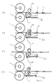
- FIG. 2 shows an expression of such an alignment station according to the invention.
- the drawings 2A to 2D show the individual process steps.
- the arcuate carrier materials (20) are fed in a scale flow of the alignment station.
- the scale flow has a bottom or overlap (19).
- the leading edge stop (8) and the leading edge stops (8) are shown in this version as a front edge stops (8) which can be pivoted into the transport plane. In the following, for simplification reasons, it is always referred to as a leading edge stop, but the leading edge stop may comprise one or more stops.
- the front edge stop (8) is pivoted into the transport plane and the first sheet in the transport direction in front of the leading edge stop (8) aligns therewith.
- the feed means (10) is designed here as two corresponding rollers (10a, 10b), which are arranged above and below the transport plane. These corresponding rolls may each be a continuous roll, profiled rolls, split rolls or a plurality of individual rolls. These are separated in process step one and have at most a slight contact with the carrier material.
- the advancing means (10) is lowered, swiveled or otherwise delivered so as to have a defined contact with the sheet-shaped carrier material located in the alignment station.
- the delivery takes place at a time prior to the removal of the leading edge stop (8) from the transport plane, ie the feed means is seated on a stationary support material and can produce an almost slip-free press contact.
- the delivery of the feed means (10) approximately simultaneously or simultaneously with the Remove the leading edge stop (8) from the transport plane.
- the delivery of the two corresponding rollers (10a, 10b) of the feed means can be done by the provision of a roller against a fixed roller or by the provision of two movable rollers to each other.
- the contact pressure of the rollers (10a, 10b) is ideally adjustable.
- the delivery can be done by adjustable springs, pneumatic or hydraulic Beistellstoff, controllable cams or electrical means (motors, etc.).
- the leading edge stop (8) is moved out of the transport plane, and a feed rate is imposed on the arcuate carrier material by means of the supplied and driven feed means.
- the pre-aligned sheet-shaped carrier material is supplied to the laminating gap, which is formed from the laminating roller (2) and the counter-pressure roller (3).
- the carrier material is bonded to the printed roller conveyor under the action of pressure and optionally heat with the aid of an adhesive.
- step 4 (2D) the leading edge stop (8) is again moved into the transport plane.
- the sheet-shaped carrier material is brought to the front edge stop (8) and the feed means (10) exerts no pressure on the carrier material.
- the two corresponding rollers (10a, 10b) of the feed means are separated.
- FIG. 3 the execution is off FIG. 2 supplemented with an additional feed means (23) which is arranged between the alignment station and the laminating gap.
- the advancing means upstream of the leading edge stop (8) in the process running direction must only take over the acceleration up to the leading edge stop (8), which feeds the further transport.
- the first feed means in the process direction can then be separated so that more time is available for alignment and force build-up.
- Feeding means (10, 23) in the form of corresponding rolls can be any roll combination of metal and elastomer-related rolls.
- One or both rollers of the feed means (10,23) can as Suction rollers be executed with openings in the lateral surface.
- a roller may be designed as a magnetic roller which exerts a magnetic force on the carrier material. Ideally, the magnetic force is switched off and / or umpolbar. This can be ensured by a solenoid roller or a switchable, eg bistable permanent magnet.
- the feed means (24) consists of at least one linear drive or with a servomotor driven belt drive.
- At the feed means is one or more suckers, which fix the carrier material pneumatically or switchable magnets for the transport of metal sheets. It can be arranged across the width of several such feed means, which can also work alternately. Alternating means that one group of feed means carries out the transport of the carrier material while another group of feed means is just running back towards the aligning station to pick up the next sheet.
- the recording of the carrier material takes place, as in FIG. 4B shown in front of the leading edge stop (8). With the lifting sucker (25) or magnet (25), the carrier material is detected and transported in the direction of laminating gap ( FIG. 4C ). Thereafter, the Hubsauger (25) or magnet (25) runs back.
- FIG. 4 In a second version of the execution in FIG. 4 (not shown) is the linear or belt drive only to accelerate the substrate. Thereafter, it is from a second feed means, for example a corresponding pair of rollers as in FIG. 3 recorded and transported by this towards laminating.
- a second feed means for example a corresponding pair of rollers as in FIG. 3 recorded and transported by this towards laminating.
- These types of drives have the advantage that they allow a very exact and predefinable carrier material transport.
- This type of feed can, as in FIG. 4 shown above the transport plane and / or be arranged below the transport plane.
- the roller conveyor advantageously consists of a transparent film material printed with at least one image or text information.
- the printed image repeats itself in fixed repeat intervals with small deviations, but may well have changing contents. This can be achieved by the film in a digital printing process, such as toner or Inkjet printing is printed.
- the film can also be printed in a printing process such as offset printing, gravure or flexographic printing with a static content.
- a combination of a printed in flexo, offset or gravure printing image with a digital printing process printed content is conceivable.
- the printed image is ideally located on the side of the film web, which is later laminated in the laminating gap against the sheet-shaped carrier material.
- the transparent film then serves as protection and refinement of the printed image.
- the film web may also be a non-transparent material, for example a metal foil or a metallized film.
- the printed image must be on the side that is not directed against the substrate in the laminating gap.
- the sensor device (7) must be rebuilt so that it is directed against the inside of the film in the departure of the film transport in the laminating (1).
- the laminating unit can also have two sensor devices (7), which are directed against both sides of the roller conveyor (6). In this case, depending on the application between the two sensor devices and switched back and forth.
- precursors for the production of folding boxes, tubes or cans can be produced. It is also conceivable plates or glass for architectural applications, automotive or for the production of household appliances with a pictorial motif equip.
Abstract
Description
Die Erfindung betrifft eine Vorrichtung zum Beschichten eines bogenförmigen Trägermaterials mit einem bahnförmigen Beschichtungsmaterial.The invention relates to a device for coating a sheet-shaped carrier material with a sheet-like coating material.
Die Erfindung ist eine Weiterentwicklung bekannter Laminiermaschinen für die Lamination von Kunststoffolien auf bogenförmigen Trägermaterialien. Ein gattungsgemässer Vertreter einer solchen Laminiermaschine ist in der
Derartige Laminiermaschinen zeichnen sich dadurch aus, dass eine relative dünne Folie von einer Rolle endlos abgenommen wird und in einem Kaschierwerk mit dem bogenförmigen Trägermaterial zu einer Laminatbahn verbunden wird. Diese Laminatbahn wird anschliessend durch eine Trenneinrichtung wieder in einzelne Laminatbogen aufgetrennt. Das Trägermaterial wird von einer Bogentrennvorrichtung von einem Stapel abgenommen und dem Kaschierwerk in einem Schuppenstrom oder Stoss an Stoss zugeführt.Such laminating machines are characterized in that a relatively thin film is removed from a roll endlessly and in one Laminating is connected to the sheet-shaped carrier material to a laminate web. This laminate web is then separated again by a separating device into individual laminate sheets. The carrier material is removed from a stack by a sheet separating device and fed to the laminating unit in a shingled stream or a joint in shock.
Aus der
Ferner ist bekannt, dass Laminiermaschinen eine Ausrichtstation aufweisen, in der der Bogen an seiner Vorderkante an Vorderkanten (Anschlagmittel für die Bogenvorderkante) und gegebenenfalls seitlich durch eine Seitenziehmarke ausgerichtet wird. Hier zeigt die
Der Nachteil der bekannten Ausrichtstationen an Laminiermaschinen ist, dass diese unmittelbar der Bogentrennstation, zum Beispiel einem Bogenanleger, zugeordnet sind. Der Schuppenstrom wird dann über Transportbänder der Kaschierstation zugeführt, wobei die Bögen auf dem Transportweg diverse Vorbehandlungen erfahren.. Dies sind üblicherweise Bogenreinigungsstationen, wie Bürstenreinigungswerke und / oder Kalanderwerke) und / oder Vorbehandlungsstationen wie zum Beispiel eine Corona -Anlage zur Erhöhung der Oberflächenspannung.The disadvantage of the known alignment stations on laminating machines is that they are directly associated with the sheet separation station, for example a sheet feeder. The shingled stream is then fed to the laminating station via conveyor belts, the sheets undergoing various pretreatments on the transport path. These are usually sheet cleaning stations, such as brush cleaning plants and / or calendering plants) and / or pretreatment stations, such as a corona plant for increasing the surface tension.
Ist das Ziel eine sehr exakte Zuführung eines Bogens in das Kaschierwerk, ist eine Laminiermaschine weniger geeignet. Die Transportbänder weisen Toleranzen auf und auch jede Behandlungsstation birgt die Gefahr, dass die Bogenlage leicht verändert wird. So können zum Beispiel die Bürsten einer Bürstenstation bei unterschiedlichen Borstenlängen die Lage des Bogens auf dem Transportband leicht verändern. Es ist zum Beispiel auch bekannt, dass der Bogenlauf durch die Einwirkung einer Corona leicht gebremst wird. Die zuvor in der Ausrichtstation ausgerichteten Stationen können auf dem Weg in das Kaschierwerk an Lagegenauigkeit verlieren.If the goal is a very precise feeding of a sheet into the laminating unit, a laminating machine is less suitable. The conveyor belts have tolerances and also each treatment station carries the risk that the sheet position is slightly changed. For example, the brushes of a brush station with different bristle lengths can easily change the position of the sheet on the conveyor belt. It is also known, for example, that the sheet travel is easily braked by the action of a corona. The previously aligned in the alignment station stations can lose their positional accuracy on the way to the laminating.
Eine sehr genaue Ausrichtung ist jedoch erforderlich, wenn ein auf Rollenmaterial befindliches Druckbild passgenau auf einem bogenförmigen Trägermaterial auflaminiert werden soll. Die Vorderkante Druckbilds muss dann in engen Toleranzen mit der Vorderkante des bogenförmigen Trägermaterials synchronisiert werden. Die erforderlichen Lagetoleranzen liegen in einem Bereich von 2/1 Omm und darunter, da ansonsten die Weiterverarbeitung der Druckprodukte (zum Beispiel Schneiden, Stanzen, Falzen etc.) nicht mehr lagegerecht möglich ist. Zu grosse Toleranzen wirken auf den Betrachter störend und das Material wird Ausschuss.However, a very precise alignment is required if a print image located on roll material is to be precisely laminated on an arcuate carrier material. The leading edge of the printed image must then be synchronized with the front edge of the sheet-like substrate in close tolerances. The required positional tolerances are within a range of 2/1 mm and below, since otherwise the further processing of the printed products (for example cutting, punching, folding etc.) is no longer possible in a correct position. Too large tolerances have a disturbing effect on the viewer and the material becomes reject.
Die
Regelungstechnisch ist eine solche Regelung auch sehr kritisch. Zwei Parameter werden erfasst, die beide Schwankungen unterliegen können. Zum Beispiel kann die Rollenbahn durch schlechte Aufrollung Zonen unterschiedlicher Dehnung aufweisen und das bogenförmige Trägermaterial die üblichen Transportschwankungen. Der Vorschub des bogenförmigen Trägermaterials wird schlimmstenfalls durch zwei variierende Signale zum Zwecke der Synchronisation gesteuert. Dies kann zu Aufschaukeleffekten und instabilen Regelungsverhältnissen führen.Control technology, such a scheme is also very critical. Two parameters are detected, which can be subject to both variations. For example, the roller conveyor may have zones of different elongation due to poor reeling, and the arched carrier material may have the usual transport fluctuations. The feed of the sheet-shaped substrate is controlled at worst by two varying signals for the purpose of synchronization. This can lead to rocking effects and unstable control conditions.
Ziel der Erfindung ist es mit einem geringeren Regelaufwand eine sehr gute Synchronisation zwischen einem auf einer Rollenbahn befindlichen Druckbild und einem bogenförmigen Trägermaterial zu erzielen, so dass beide Materialien in einem Kaschierspalt einer Laminiermaschine passgerecht zu einem Laminat verbunden werden.The aim of the invention is to achieve a very good synchronization between a printed image located on a roller conveyor and a sheet-like carrier material with a lower control effort, so that both materials are properly connected in a laminating nip a laminating machine to form a laminate.
Zur Lösung der Aufgabe führt der kennzeichnende Teil von Anspruch 1.To achieve the object of the characterizing part of claim 1.
Die von einem erfindungsgemäss hergestellten und betriebenen Laminiermaschine gebotene Vorteile liegen in erster Linie darin, dass registergenau / passgenau ein auf einer Rollenbahn befindliches Druckbild auf ein bogenförmiges Trägermaterial auflaminiert werden kann, ohne dass auf eine aufwendige, fehleranfällige Sensorik und Regelungstechnik zurückgegriffen werden muss.The advantages offered by a laminating machine produced and operated according to the invention are first and foremost that a printed image located on a roller conveyor can be laminated onto a sheet-like carrier material without the need for expensive, error-prone sensor technology and control technology.
Dieser positive Effekt wird erzielt, indem unmittelbar vor dem Kaschierspalt eine Ausrichtstation angeordnet ist, die mindestens einen mechanischen Vorderkantenanschlag aufweist, an dem sich der Bogen an der Vorderkante ausrichtet. Nach erfolgtem Ausrichtvorgang wird das bogenförmige Trägermaterial durch eine Vorschubvorrichtung direkt in den Kaschierspalt geschoben. Jedes bogenförmige Trägermaterial wird somit vor dem Einlauf auf eine vordefinierte Position gebracht.This positive effect is achieved by an alignment station is arranged immediately before the laminating gap, which has at least one mechanical leading edge stop, at which the arc at the front edge aligns. After the alignment process, the sheet-shaped carrier material is pushed by a feed device directly into the laminating gap. Each arcuate carrier material is thus brought to a predefined position before the inlet.
Dagegen müssen Systeme, die eine oder mehrere Druckmarken oder Bildbestandteile auf der Rollenbahn abtasten und gleichzeitig die Kante des bogenförmigen Trägermaterials abtasten, den Bogentransport des Trägermaterials Einzelbogen bezogen überwachen. Die bogenförmigen Trägermaterialien können sich, wie zuvor schon erwähnt, während des Transports von der Entstapelungsvorrichtung bis zu Kaschierspalt verschieben. Das heisst, die Kante des bogenförmigen Trägermaterials muss vor dem Einlauf in das Kaschierwerk erfasst und auf den einzelnen Bogen bezogen eine Vorschubgeschwindigkeit ermittelt werden, damit eine Synchronisation des Transports des bogenförmigen Trägermaterials mit dem Druckbild auf der Rollenbahn erfolgen kann. Dies bedeutet, dass das bogenförmige Trägermaterial zum Zwecke der Synchronisation beschleunigt bzw. verzögert werden muss. Dies führt bei einer nichts sehr präzisen Transport aufgrund sich gegebenenfalls ständig ändernden Schlupfverhältnissen. Eine Regelung der Rollenbahn schliesst sich in der Regel aus, da variierende Rollenbahngeschwindigkeiten zu unterschiedlichen Dehnverhältnissen führen können Dies ist insbesondere bei bedruckten, oftmals nur 10-12mm dicken Folienbahnen der Fall, wie sie in dieser Anwendung häufig eingesetzt werden.By contrast, systems which scan one or more print marks or image components on the roller conveyor and at the same time scan the edge of the sheet-shaped carrier material must monitor the sheet transport of the carrier material with respect to individual sheets. As already mentioned above, the sheet-shaped carrier materials may shift during transport from the unstacking device to the laminating gap. That is, the edge of the sheet-shaped carrier material must be detected prior to entry into the laminating and based on the individual sheet a feed rate can be determined so that a synchronization of the transport of the sheet-shaped carrier material can be done with the printed image on the roller conveyor. This means that the arcuate carrier material has to be accelerated or decelerated for the purpose of synchronization. This results in a not very precise transport due to possibly constantly changing slip conditions. A regulation of the roller conveyor usually precludes, since varying roller conveyor speeds can lead to different Dehnverhältnissen This is particularly the case with printed, often only 10-12mm thick film webs the case, as they are often used in this application.
Dagegen wird in der erfindungsgemässen Lösung jedes bogenförmige Trägermaterial kurz vor dem Kaschier an mindestens einem Vorderkantenanschlag ausgerichtet und somit mechanisch in eine vordefinierte Position gebracht. Von dieser Referenzposition kann jedes bogenförmige Trägermaterial bei einer konstanten Maschinengeschwindigkeit mit einer gleichbleibenden Vorschubgeschwindigkeit in den Kaschierspalt eingebracht werden. Mit dieser erfindungsgemässen Lösung wird der Regelungs- und Steuerungsaufwand deutlich reduziert. Ferner werden Fehlerquellen, die bei Erfassung der Vorderkante des bogenförmigen Trägermaterials störend wirken können, ausgeschlossen. Typische Fehlerquellen sind ungleichmässige Vorderkanten, stark reflektierendes Trägermaterial oder Vibrationen, wie sie bei sehr schweren Trägermaterialien, wie zum Beispiel Metallplatten, auftreten können. Die erfindungsgemäss gefundene Lösung stellt daher ein prozesstechnisch sicheres und kostengünstiges Produktionssystem dar.In contrast, in the solution according to the invention, each sheet-shaped carrier material is aligned shortly before the liner on at least one leading edge stop and thus brought mechanically into a predefined position. From this reference position each arcuate carrier material can be introduced at a constant machine speed with a constant feed rate in the laminating gap. With this inventive solution, the control and control effort is significantly reduced. Furthermore, sources of error that can interfere with the detection of the leading edge of the sheet-shaped carrier material are excluded. Typical sources of error are uneven leading edges, highly reflective substrate material or vibrations, such as those at very heavy support materials, such as metal plates may occur. The inventively found solution therefore represents a process-technically safe and cost-effective production system.
Bevorzugte Ausführungsformen, die für die Erfindung wesentliche Merkmale aufweist, werden anhand der Zeichnungen beschrieben. Es zeigen dabei die Zeichnungen:
-
Figur 1 : eine vereinfachte schematische Ansicht einer erfindungsgemässen Laminiermaschine, wobei nur der Bereich von einer Entstapelungseinrichtung bis zu einem Kaschierwerk aufgezeigt wird. Eine dem Kaschierwerk nachfolgende Bearbeitungsstationen und Abstapeleinrichtungen wurden vernachlässigt. -
Figuren 2A-2D : Detailansichten einer ersten Ausführung einer erfindungsgemässen Ausrichtstation, wobei die einzelnen Abiaufschritte des Ausrichte- und Transportablaufs in Teilzeichnungen dargelegt wird. -
Figuren 3A - 3D : Detailansichten einer zweiten Ausführung einer erfindungsgemässen Ausrichtstation, wobei die einzelnen Abiaufschritte des Ausrichte- und Transportablaufs in Teilzeichnungen dargelegt wird. -
Figuren 4A-4D : Detailansichten einer dritten Ausführung einer erfindungsgemässen Ausrichtstation, wobei die einzelnen Abiaufschritte des Ausrichte- und Transportablaufs in Teilzeichnungen dargelegt wird.
-
FIG. 1 : A simplified schematic view of a laminating machine according to the invention, wherein only the area from a destacking device to a laminating unit is shown. A processing stations and stacking devices following the laminating unit were neglected. -
Figures 2A-2D : Detailed views of a first embodiment of an inventive alignment station, the individual Abiaufschritte the alignment and transport process is set out in partial drawings. -
FIGS. 3A-3D : Detail views of a second embodiment of an inventive alignment station, wherein the individual Abiaufschritte the Ausrichte- and transport process is set out in part drawings. -
Figures 4A-4D : Detailed views of a third embodiment of an inventive alignment station, the individual Abiaufschritte the alignment and transport process is set out in partial drawings.
In den beigefügten Zeichnungen handelt es sich bei
Ein Kaschierwerk (1) weist mindestens eine Abrollung (4) auf, in der eine Rollenbahn (6) von einer Vorratsrolle abgerollt wird. Die Rollenbahn (6) wird nach der Abrollung (4) mit einem Kleberauftragswerk (5) mit Klebstoff beschichtet. In der schematischen Zeichnung ist ein Rollenauftragswerk als Kleberauftragswerk (5) dargestellt. Das Kleberauftragswerk (5) kann aber ebenfalls als ein Sprühkleberauftragswerk mit Düsen, als ein Breitschlitzdüsenauftragswerk oder als ein Vorhangauftragswerk ausgeführt sein. Die Art des Kleberauftrags ist nicht erfindungswesentlich. Als Klebstoffe kommen Dispersionsklebstoffe, Ein- oder Zweikomponenten Polyurethan Klebstoffe, Reaktive Schmelzklebstoffe, z.B. auf Polyurethan - Basis oder einfache Schmelzklebstoffe in Frage. Die Art des Klebstoffes ist nicht erfindungswesentlich, jeder für den Anwendungsfall geeignete Klebstoff kann eingesetzt werden.A laminating unit (1) has at least one unwinding unit (4), in which a roller conveyor (6) is unrolled from a supply roll. The roller conveyor (6) is coated after the unwinding (4) with an adhesive applicator (5) with adhesive. In the schematic drawing, a Rollenauftragswerk is shown as Kleberauftragswerk (5). However, the glue applicator (5) may also be embodied as a spray glue applicator with nozzles, as a slot die applicator, or as a curtain applicator. The type of adhesive application is not essential to the invention. Adhesives are dispersion adhesives, one or two component polyurethane adhesives, reactive hot melt adhesives, e.g. based on polyurethane or simple hotmelt adhesives in question. The type of adhesive is not essential to the invention, any suitable adhesive for the application can be used.
Die mit dem Klebstoff beschichtete Rollenbahn (6), die mindestens ein Druckbild trägt, wird dann mit einer optischen Sensoreinrichtung (7) abgetastet. Diese Sensoreinrichtung (7) kann auf Druckmarken, zum Beispiel Registermarken, und /oder Teile des Druckbilds abgestimmt sein. Die Sensoreinrichtung (7) kann aus einem oder mehreren, zum Beispiel über die Rollenbreite nebeneinander angeordneten optischen Sensoren bestehen. Eine geeignete optische Sensoreinrichtung (7) könnte zum Beispiel aus Laserabtastköpfen bestehen. Die Sensoreinrichtung (7) kann alternativ oder ergänzend eine oder mehreren Kameras mit einer nachgeschalteten Bildverarbeitung aufweisen, die Teil des Druckbildes oder spezielle Marken auswerten.The coated with the adhesive roller conveyor (6), which carries at least one printed image is then scanned with an optical sensor device (7). This sensor device (7) can be matched to print marks, for example register marks, and / or parts of the printed image. The sensor device (7) may consist of one or more, for example, over the roller width juxtaposed optical sensors. A suitable optical sensor device (7) could for example consist of laser scanning heads. The sensor device (7) may alternatively or additionally comprise one or more cameras with a downstream image processing that evaluate part of the printed image or special marks.
Das Signal der Sensoreinrichtung (7) dient als Triggersignal für die Ansteuerung der Ausrichtstation, die in unmittelbarer Nähe des Kaschierspalts angeordnet ist. Die Ausrichtstation weist mindestens einen versenkbaren, wegschwenkbaren oder in einer anderen geeigneten Form wegbewegbaren Vorderkantenanschlag (8) auf, der zum Zeitpunkt der Ausrichtung so in die Transportebene hereinragt, dass das bogenförmige Trägermaterial sich an der Vorderkante ausrichtet. Die Ausrichtstation kann ebenfalls eine Vorrichtung zum seitlichen Ausrichten aufweisen, indem das bogenförmige Trägermaterial durch eine Ziehmarke gegen einen seitlichen Anschlag gezogen wird oder durch eine Stossrharke mit einem Anschlag auf eine vorbestimmte Position geschoben wird. Die seitliche Ausrichtung kann ebenfalls ergänzend oder alternativ geschehen, indem ein seitlicher Anschlag schräg in die Transportebene hereinragt und das bogenförmige Trägermaterial sich während des Transports an diesem ausrichtet. Die Einrichtungen zur seitlichen Ausrichtung sind zeichnerisch nicht dargestellt. Ferner weist die Ausrichtstation mindestens ein Vorschubmittel (10) auf, die das ausgerichteten Bogen aus dem Ausrichtzustand wieder beschleunigt. Verschiedene Ausführungen eines solchen Vorschubmittels (10) werden in den
Aus dem Triggersignal der Sensoreinrichtung (7) wird in einem Rechner (21) unter Berücksichtigung mindestens des Parameters Prozessgeschwindigkeit der Öffnungszeitpunkt des Vorderkantenanschlags (8) und die Geschwindigkeit des Vorschubmittels (10) bestimmt. Dies kann anhand einer Berechnungsvorschrift und / oder hinterlegten Kennlinien erfolgen, die alle erforderlichen Parameter berücksichtigen. Das Vorschubmittel (10) weist dabei mindestens einen steuerbaren Antrieb auf.From the trigger signal of the sensor device (7), the opening time of the leading edge stop (8) and the speed of the feed device (10) are determined in a computer (21) taking into account at least the parameter process speed. This can be done using a calculation rule and / or stored characteristics that take into account all required parameters. The feed means (10) has at least one controllable drive.
Nach dem Verlassen der Ausrichtstation erreicht das bogenförmige Trägermaterial den Kaschierspalt, der aus der Kaschierwalze (3) und der Gegendruckwalze (2) gebildet wird. In dem Kaschierspalt wird das bogenförmige Trägermaterial mit der mit Klebstoff beschichteten Rollenbahn (6) unter Einwirkung von Druck und gegebenenfalls Wärme zu einer Laminatbahn verbunden. Diese Laminatbahn wird nach dem Verlassen des Kaschierspaltes durch eine Trenneinrichtung wieder in einzelne Laminatbogen aufgetrennt. Die Trenneinrichtung ist in der Zeichnung nicht dargestellt. Die Trennung kann durch einen Laserschnitt, durch ein rotierendes oder taktendes Messer, ein rotierendes oder taktendes Heisstrennmesser oder durch Reissen geschehen. Die einzelnen Laminatbogen werden dann auf einen Ablagestapel abgestapelt oder einer weiteren Bearbeitungsstation zugeführt.After leaving the alignment station, the sheet-shaped carrier material reaches the laminating gap, which is formed by the laminating roller (3) and the counterpressure roller (2). In the laminating gap, the sheet-shaped carrier material is bonded to the adhesive-coated roller conveyor (6) under the action of pressure and optionally heat to form a laminate web. This laminate web becomes after leaving the laminating slit separated again by a separating device into individual laminate sheets. The separator is not shown in the drawing. The separation can be done by a laser cut, by a rotating or clocking knife, a rotating or clocking hot knife or by tearing. The individual laminate sheets are then stacked on a discard pile or fed to another processing station.
In dem Prozessschritt 2 (2B) wird das Vorschubmittel (10) abgesenkt, angeschwenkt oder in einer anderen Art zugestellt, so dass sie einen definierten Kontakt zu dem bogenförmigen Trägermaterial haben, das sich in der Ausrichtstation befindet. Idealerweise erfolgt die Zustellung zu einem Zeitpunkt vor dem Entfernen des Vorderkantenanschlags (8) aus der Transportebene, d.h. das Vorschubmittel setzt auf einem ruhenden Trägermaterial auf und kann annährend schlupffrei einen Presskontakt herstellen. Alternativ kann die Zustellung des Vorschubmittels (10) annährend zeitgleich bzw. zeitgleich mit dem Entfernen des Vorderkantenanschlags (8) aus der Transportebene geschehen. Die Zustellung der beiden korrespondierenden Walzen (10a, 10b) des Vorschubmittels kann durch die Beistellung einer Walze gegen eine feststehende Walze oder durch die Beistellung zweier beweglicher Walzen zueinander geschehen. Die Anpresskraft der Walzen (10a, 10b) ist idealerweise einstellbar. Die Zustellung kann durch einstellbare Federn, pneumatische oder hydraulische Beistellmittel, steuerbare Kurvenscheiben oder elektrische Mittel (Motoren etc.) geschehen.In process step 2 (Fig. 2B), the advancing means (10) is lowered, swiveled or otherwise delivered so as to have a defined contact with the sheet-shaped carrier material located in the alignment station. Ideally, the delivery takes place at a time prior to the removal of the leading edge stop (8) from the transport plane, ie the feed means is seated on a stationary support material and can produce an almost slip-free press contact. Alternatively, the delivery of the feed means (10) approximately simultaneously or simultaneously with the Remove the leading edge stop (8) from the transport plane. The delivery of the two corresponding rollers (10a, 10b) of the feed means can be done by the provision of a roller against a fixed roller or by the provision of two movable rollers to each other. The contact pressure of the rollers (10a, 10b) is ideally adjustable. The delivery can be done by adjustable springs, pneumatic or hydraulic Beistellmittel, controllable cams or electrical means (motors, etc.).
In dem Prozessschritt 3 (2C) werden der Vorderkantenanschlag (8) aus der Transportebene herausbewegt und dem bogenförmige Trägermaterial wird durch die beigestellten und angetriebenen Vorschubmittel eine Vorschubgeschwindigkeit aufgeprägt. Das vorab ausgerichtete bogenförmige Trägermaterial wird dem Kaschierspalt zugeführt, der aus der Kaschierwalze (2) und der Gegendruckwalze (3) gebildet wird. In dem Kaschierspalt wird das Trägermaterial unter Einwirkung von Druck und gegebenenfalls Wärme unter Zurhilfenahme eines Klebstoffes mit der bedruckten Rollenbahn verbunden.In the process step 3 (FIG. 2C), the leading edge stop (8) is moved out of the transport plane, and a feed rate is imposed on the arcuate carrier material by means of the supplied and driven feed means. The pre-aligned sheet-shaped carrier material is supplied to the laminating gap, which is formed from the laminating roller (2) and the counter-pressure roller (3). In the laminating gap, the carrier material is bonded to the printed roller conveyor under the action of pressure and optionally heat with the aid of an adhesive.
In dem Prozessschritt 4 (2D) wird der Vorderkantenanschlag (8) wieder in die Transportebene hineinbewegt. Das bogenförmige Trägermaterial wird an den Vorderkantenanschlag (8) herangeführt und das Vorschubmittel (10) übt keinen Druck auf das Trägermaterial aus. In diesem konkreten Fall sind die zwei korrespondierenden Walzen (10a, 10b) des Vorschubmittels getrennt.In the process step 4 (2D), the leading edge stop (8) is again moved into the transport plane. The sheet-shaped carrier material is brought to the front edge stop (8) and the feed means (10) exerts no pressure on the carrier material. In this specific case, the two corresponding rollers (10a, 10b) of the feed means are separated.
In
Vorschubmittel (10,23) in Form von korrespondierenden Walzen können eine beliebige Walzenkombination aus Metall- und elastomerbezogenen Walzen darstellen. Eine oder beide Walzen des Vorschubmittels (10,23) kann / können als Saugwalzen ausgeführt sein mit Öffnungen in der Mantelfläche. In einer besonderen Ausführung für den Transport metallischer Trägermaterialien kann eine Walze als Magnetwalze ausgeführt sein, die eine Magnetkraft auf das Trägermaterial ausübt. Idealerweise ist die Magnetkraft abschaltbar und / oder, umpolbar. Dies kann durch einen Elektromagnetwalze oder einen schaltbaren, z.B. bistabilen Dauermagneten gewährleistet sein.Feeding means (10, 23) in the form of corresponding rolls can be any roll combination of metal and elastomer-related rolls. One or both rollers of the feed means (10,23) can as Suction rollers be executed with openings in the lateral surface. In a particular embodiment for the transport of metallic carrier materials, a roller may be designed as a magnetic roller which exerts a magnetic force on the carrier material. Ideally, the magnetic force is switched off and / or umpolbar. This can be ensured by a solenoid roller or a switchable, eg bistable permanent magnet.
In der
In einer zweiten Version der Ausführung in
Die Rollenbahn besteht in vorteilhafter Weise aus einem transparenten mit mindestens einer Bild- oder Textinformation bedruckten Folienmaterial. Das Druckbild wiederholt sich in festen Rapportabständen mit geringen Abweichungen, kann aber durchaus sich verändernde Inhalte aufweisen. Dies kann erreicht werden, indem die Folie in einem Digitaldruckverfahren, z.B. Toner- oder Inkjetdruck bedruckt wird. Alternativ kann die Folie auch in einem Druckverfahren wie dem Offsetdruck, Tief- oder Flexodruck mit einem statischen Inhalt bedruckt werden. Auch ist eine Kombination eines im Flexo-, Offset- oder Tiefdruck gedruckten Bildes mit einem Digitaldruckverfahren gedruckten Inhalt denkbar. Das Druckbild befindet sich idealerweise auf der Seite der Folienbahn, die in dem Kaschierspalt später gegen das bogenförmige Trägermaterial kaschiert wird. Die transparente Folie dient dann als Schutz und Veredelung des Druckbildes. Als Folienmaterial sind alle gängigen Folientypen denkbar. Besonders geeignet ist Polyester, BOPP und andere dehnungsarme Kunststoffe. Die Folienbahn kann aber auch eine nicht transparentes Material sein, z.B. eine Metallfolie oder eine metallisierte Folie. In diesem Fall muss das Druckbild sich auf der Seite befinden, die im Kaschierspalt nicht gegen das Trägermaterial gerichtet ist. In diesem Fall muss die Sensoreinrichtung (7) so umgebaut werden, dass sie gegen die Innenseite der Folie im Abgang des Folientransports im Kaschierwerk (1) gerichtet ist. Das Kaschierwerk kann auch zwei Sensoreinrichtungen (7) aufweisen, die gegen beide Seiten der Rollenbahn (6) gerichtet sind. In diesem Fall kann je nach Anwendungsfall zwischen den beiden Sensoreinrichtungen hin- und hergeschaltet werden.The roller conveyor advantageously consists of a transparent film material printed with at least one image or text information. The printed image repeats itself in fixed repeat intervals with small deviations, but may well have changing contents. This can be achieved by the film in a digital printing process, such as toner or Inkjet printing is printed. Alternatively, the film can also be printed in a printing process such as offset printing, gravure or flexographic printing with a static content. Also, a combination of a printed in flexo, offset or gravure printing image with a digital printing process printed content is conceivable. The printed image is ideally located on the side of the film web, which is later laminated in the laminating gap against the sheet-shaped carrier material. The transparent film then serves as protection and refinement of the printed image. As foil material all common types of foil are conceivable. Particularly suitable is polyester, BOPP and other low-expansion plastics. However, the film web may also be a non-transparent material, for example a metal foil or a metallized film. In this case, the printed image must be on the side that is not directed against the substrate in the laminating gap. In this case, the sensor device (7) must be rebuilt so that it is directed against the inside of the film in the departure of the film transport in the laminating (1). The laminating unit can also have two sensor devices (7), which are directed against both sides of the roller conveyor (6). In this case, depending on the application between the two sensor devices and switched back and forth.
Mit der erfindungsgemässen Vorrichtung und Verfahren können Vorprodukte für die Herstellung von Faltschachtel, Tuben oder Dosen hergestellt werden. Auch ist es denkbar Bleche oder Glas für Architekturanwendungen, Automobilbau oder für die Herstellung von Haushaltsgeräten mit einem bildhaften Motiv auszustatten.By means of the device and method according to the invention, precursors for the production of folding boxes, tubes or cans can be produced. It is also conceivable plates or glass for architectural applications, automotive or for the production of household appliances with a pictorial motif equip.
Selbstverständlich ist die Erfindung nicht auf die zuvor aufgeführten Ausführungsbeispiele beschränkt, und es können Modifikationen innerhalb des Schutzbereichs der folgenden Ansprüche ausgeführt werden. Mit der erfindungsgemäss gefundenen Lösung wurde eine kostengünstige und regelungstechnisch stabile Lösung für eine registergenaue Laminierung von auf Rollenbahnen befindlichen Druckbildern auf bogenförmigen Trägermaterialien gegeben.Of course, the invention is not limited to the above-mentioned embodiments, and modifications may be made within the scope of the following claims. With the solution found according to the invention, a cost-effective and control-technically stable solution for register-accurate lamination of printed images on roller conveyors on sheet-shaped carrier materials was provided.
Bezeichnerliste
- 1
- Laminierwerk
- 2
- Kaschierwalze
- 3
- Gegendruckwalze
- 4
- Rollenabrollung
- 5
- Kleberauftragswerk
- 6
- Rollenabrollung
- 7
- Sensoreinrichtung
- 8
- Vorderkantenanschlag
- 9
- Vorderkantenanschlagantrieb
- 10
- Vorschubmittel (10a obere Rolle, 10b untere Rolle)
- 11
- Transportebene
- 12
- Transportrichtung
- 13
- Kalanderwerk
- 14
- Bürstenreinigungsstation
- 15
- Anlegertisch
- 16
- Entstapelungsvorrichtung (Anleger)
- 17
- Bogentrenner
- 18
- Stapel
- 19
- Unterschuppung / Unterlappung
- 20
- Schuppenstrom
- 21
- Controller
- 22
- Datenleitung
- 23
- Vorschubmittel (23a obere Rolle, 23b untere Rolle)
- 24
- Linearmotor, Linearantrieb
- 25
- Halteelement
- 1
- Laminierwerk
- 2
- laminating
- 3
- Backing roll
- 4
- Rollenabrollung
- 5
- Glue applicator unit
- 6
- Rollenabrollung
- 7
- sensor device
- 8th
- Leading-edge stop
- 9
- Leading-edge stop driving
- 10
- Feed means (10a upper roll, 10b lower roll)
- 11
- transport plane
- 12
- transport direction
- 13
- calender unit
- 14
- Brush cleaning station
- 15
- feed table
- 16
- Destacking device (feeder)
- 17
- sheet separator
- 18
- stack
- 19
- Underfinging / underlapping
- 20
- shingle stream
- 21
- controller
- 22
- data line
- 23
- Feed means (23a upper roller, 23b lower roller)
- 24
- Linear motor, linear drive
- 25
- retaining element
Claims (11)
dadurch gekennzeichnet, dass
characterized in that
Applications Claiming Priority (1)
| Application Number | Priority Date | Filing Date | Title |
|---|---|---|---|
| CH6152010 | 2010-04-27 |
Publications (1)
| Publication Number | Publication Date |
|---|---|
| EP2383117A1 true EP2383117A1 (en) | 2011-11-02 |
Family
ID=43603811
Family Applications (1)
| Application Number | Title | Priority Date | Filing Date |
|---|---|---|---|
| EP10015373A Withdrawn EP2383117A1 (en) | 2010-04-27 | 2010-12-07 | Method and apparatus for coating a sheet-shaped carrier material |
Country Status (2)
| Country | Link |
|---|---|
| EP (1) | EP2383117A1 (en) |
| DE (1) | DE202010013077U1 (en) |
Cited By (9)
| Publication number | Priority date | Publication date | Assignee | Title |
|---|---|---|---|---|
| CN104417013A (en) * | 2013-09-04 | 2015-03-18 | 佑顺发机械股份有限公司 | Shaping mechanism for single-chip double-face coating-type optical film |
| DE102015221665A1 (en) * | 2015-11-04 | 2017-05-04 | Koenig & Bauer Ag | A laminating machine and a method of laminating sheets of a material |
| WO2017076948A2 (en) | 2015-11-04 | 2017-05-11 | Koenig & Bauer Ag | Separation device for separating portions of a material web, laminating machine comprising a separation device and method for separating at least one portion of a material web |
| DE102016221530A1 (en) | 2016-11-03 | 2018-05-03 | Koenig & Bauer Ag | A laminating machine and a method of laminating sheets of a material |
| DE102016221527A1 (en) | 2016-11-03 | 2018-05-03 | Koenig & Bauer Ag | Retractable lamination machine and method for laminating a material |
| DE102016015774A1 (en) | 2016-11-03 | 2018-05-03 | Koenig & Bauer Ag | laminating |
| DE102016221528A1 (en) | 2016-11-03 | 2018-05-03 | Koenig & Bauer Ag | Separating device for separating sections of a material web and a laminating machine |
| DE102016221529A1 (en) | 2016-11-03 | 2018-05-03 | Koenig & Bauer Ag | laminating |
| US10384429B2 (en) | 2015-11-04 | 2019-08-20 | Koenig & Bauer Ag | Lamination machine and a method for laminating at least one material |
Families Citing this family (2)
| Publication number | Priority date | Publication date | Assignee | Title |
|---|---|---|---|---|
| CN102294904A (en) * | 2011-05-13 | 2011-12-28 | 深圳市贤俊龙彩印有限公司 | Laminating method and device |
| DE102011117168A1 (en) * | 2011-10-28 | 2013-05-02 | Karl W. Niemann Gmbh & Co. Kg | Laminating substrate plate with plastic film, comprises applying liquid hot melt adhesive on surface of substrate plate, smoothing applied adhesive layer, applying adhesive on back side of plastic film, and laminating plastic film |
Citations (3)
| Publication number | Priority date | Publication date | Assignee | Title |
|---|---|---|---|---|
| US5480509A (en) * | 1990-07-27 | 1996-01-02 | Canon Kabushiki Kaisha | Laminating apparatus |
| EP0586642B1 (en) | 1992-03-24 | 1996-06-19 | Ulrich Steinemann Ag | Process, device and installation for producing laminates |
| WO2006102858A2 (en) | 2005-04-01 | 2006-10-05 | Billhöfer Maschinenfabrik Gmbh & Co.Kg | Device and method for coating a metallic support material |
-
2010
- 2010-12-07 EP EP10015373A patent/EP2383117A1/en not_active Withdrawn
- 2010-12-07 DE DE202010013077U patent/DE202010013077U1/en not_active Expired - Lifetime
Patent Citations (3)
| Publication number | Priority date | Publication date | Assignee | Title |
|---|---|---|---|---|
| US5480509A (en) * | 1990-07-27 | 1996-01-02 | Canon Kabushiki Kaisha | Laminating apparatus |
| EP0586642B1 (en) | 1992-03-24 | 1996-06-19 | Ulrich Steinemann Ag | Process, device and installation for producing laminates |
| WO2006102858A2 (en) | 2005-04-01 | 2006-10-05 | Billhöfer Maschinenfabrik Gmbh & Co.Kg | Device and method for coating a metallic support material |
Cited By (20)
| Publication number | Priority date | Publication date | Assignee | Title |
|---|---|---|---|---|
| CN104417013A (en) * | 2013-09-04 | 2015-03-18 | 佑顺发机械股份有限公司 | Shaping mechanism for single-chip double-face coating-type optical film |
| DE102015221665A1 (en) * | 2015-11-04 | 2017-05-04 | Koenig & Bauer Ag | A laminating machine and a method of laminating sheets of a material |
| WO2017076948A2 (en) | 2015-11-04 | 2017-05-11 | Koenig & Bauer Ag | Separation device for separating portions of a material web, laminating machine comprising a separation device and method for separating at least one portion of a material web |
| US10384429B2 (en) | 2015-11-04 | 2019-08-20 | Koenig & Bauer Ag | Lamination machine and a method for laminating at least one material |
| US10357954B2 (en) | 2015-11-04 | 2019-07-23 | Koenig & Bauer Ag | Separating device for separating sections from a material web, laminating machine comprising a separating device, and method for laminating a sheet of a material web and for separating at least one section from a material web |
| DE102015221665B4 (en) | 2015-11-04 | 2019-01-17 | Koenig & Bauer Ag | A laminating machine and a method of laminating sheets of a material |
| WO2018082888A1 (en) | 2016-11-03 | 2018-05-11 | Koenig & Bauer Ag | Lamination machine with drawing means and a method for laminating a material |
| DE102016221527A1 (en) | 2016-11-03 | 2018-05-03 | Koenig & Bauer Ag | Retractable lamination machine and method for laminating a material |
| WO2018082890A1 (en) | 2016-11-03 | 2018-05-11 | Koenig & Bauer Ag | Laminating machine, and a method for laminating sheets of a material |
| WO2018082889A1 (en) | 2016-11-03 | 2018-05-11 | Koenig & Bauer Ag | Laminating machine |
| DE102016221528A1 (en) | 2016-11-03 | 2018-05-03 | Koenig & Bauer Ag | Separating device for separating sections of a material web and a laminating machine |
| DE102016015774A1 (en) | 2016-11-03 | 2018-05-03 | Koenig & Bauer Ag | laminating |
| CN109906149A (en) * | 2016-11-03 | 2019-06-18 | 柯尼格及包尔公开股份有限公司 | Laminating machine |
| DE102016221529A1 (en) | 2016-11-03 | 2018-05-03 | Koenig & Bauer Ag | laminating |
| DE102016221530A1 (en) | 2016-11-03 | 2018-05-03 | Koenig & Bauer Ag | A laminating machine and a method of laminating sheets of a material |
| US10717258B2 (en) | 2016-11-03 | 2020-07-21 | Koenig & Bauer Ag | Laminating machine, and a method for laminating sheets of a material |
| US10766240B2 (en) | 2016-11-03 | 2020-09-08 | Koenig & Bauer Ag | Lamination machine with drawing means and a method for laminating a material |
| US10821716B2 (en) | 2016-11-03 | 2020-11-03 | Koenig & Bauer Ag | Laminating machine |
| DE102016015774B4 (en) | 2016-11-03 | 2021-07-22 | Koenig & Bauer Ag | Lamination machine |
| DE102016221528B4 (en) | 2016-11-03 | 2024-01-11 | Koenig & Bauer Ag | Lamination machine with a separating device for separating sections from a material web |
Also Published As
| Publication number | Publication date |
|---|---|
| DE202010013077U1 (en) | 2011-02-17 |
Similar Documents
| Publication | Publication Date | Title |
|---|---|---|
| EP2383117A1 (en) | Method and apparatus for coating a sheet-shaped carrier material | |
| EP3370960B1 (en) | Lamination machine and a method for laminating at least one material | |
| DE102011006905A1 (en) | Machine for making books, in particular photo books and / or picture books | |
| EP1500504B1 (en) | Apparatus for printing flat articles produced from wood-fibre material | |
| EP3370934B1 (en) | Separation device for separating portions of a material web, laminating machine comprising a separation device and method for separating at least one portion of a material web | |
| DE102007058765A1 (en) | Labeling machine for linerless labels | |
| DE102015221664B4 (en) | Laminating machine and a method for laminating a material | |
| EP3535124B1 (en) | Laminating machine | |
| DE102015221666A1 (en) | Laminating machine and a method for laminating a material | |
| DE102016015774B4 (en) | Lamination machine | |
| EP3535125A1 (en) | Lamination machine with drawing means and a method for laminating a material | |
| EP2227428B1 (en) | Method and apparatus for transporting paper in a paper-handling system from a first transport means to a second transport means | |
| EP3272548A1 (en) | Machine for the automated production of book covers | |
| DE4332186C2 (en) | Method and device for laminating flat material blanks | |
| EP1535872B1 (en) | Cross cutter for printed materials | |
| DE202005014636U1 (en) | Sheet processing installation comprises a printing station with a double printer unit which is provided with a stream of sheets cut from a continuous material strip | |
| EP3535123A1 (en) | Laminating machine, and a method for laminating sheets of a material | |
| DE10315648A1 (en) | Device for the sheet-by-sheet feeding of sheet-shaped printing materials from a stack to a transport path entrance | |
| DE19523363B4 (en) | Method and device for continuous laying of individual sheets on a strand of successive plates or on a carrier web | |
| DE102016221528B4 (en) | Lamination machine with a separating device for separating sections from a material web | |
| DE102015221662B4 (en) | Separating device for separating sections from a web of material | |
| DE102007005000A1 (en) | Application device for e.g. individual chips, has conveying device for transporting pre-cut parts of folding box from feeder to applicator with less inclination angle and conveying parts from applicator | |
| DE102022105319A1 (en) | Device for transporting substrate sheets and machine | |
| DE102019111857A1 (en) | Hot stamping press | |
| EP3994087A1 (en) | Sheet processing machine with at least one sheet storage device, and method for storing sheets |
Legal Events
| Date | Code | Title | Description |
|---|---|---|---|
| AK | Designated contracting states |
Kind code of ref document: A1 Designated state(s): AL AT BE BG CH CY CZ DE DK EE ES FI FR GB GR HR HU IE IS IT LI LT LU LV MC MK MT NL NO PL PT RO RS SE SI SK SM TR |
|
| AX | Request for extension of the european patent |
Extension state: BA ME |
|
| PUAI | Public reference made under article 153(3) epc to a published international application that has entered the european phase |
Free format text: ORIGINAL CODE: 0009012 |
|
| STAA | Information on the status of an ep patent application or granted ep patent |
Free format text: STATUS: THE APPLICATION IS DEEMED TO BE WITHDRAWN |
|
| 18D | Application deemed to be withdrawn |
Effective date: 20120503 |