EP2389984A1 - Shoulder mounted hood cooling system - Google Patents
Shoulder mounted hood cooling system Download PDFInfo
- Publication number
- EP2389984A1 EP2389984A1 EP11166615A EP11166615A EP2389984A1 EP 2389984 A1 EP2389984 A1 EP 2389984A1 EP 11166615 A EP11166615 A EP 11166615A EP 11166615 A EP11166615 A EP 11166615A EP 2389984 A1 EP2389984 A1 EP 2389984A1
- Authority
- EP
- European Patent Office
- Prior art keywords
- support
- shoulder
- blower
- cooling assembly
- user
- Prior art date
- Legal status (The legal status is an assumption and is not a legal conclusion. Google has not performed a legal analysis and makes no representation as to the accuracy of the status listed.)
- Withdrawn
Links
Images


Classifications
-
- A—HUMAN NECESSITIES
- A62—LIFE-SAVING; FIRE-FIGHTING
- A62B—DEVICES, APPARATUS OR METHODS FOR LIFE-SAVING
- A62B18/00—Breathing masks or helmets, e.g. affording protection against chemical agents or for use at high altitudes or incorporating a pump or compressor for reducing the inhalation effort
- A62B18/003—Breathing masks or helmets, e.g. affording protection against chemical agents or for use at high altitudes or incorporating a pump or compressor for reducing the inhalation effort having means for creating a fresh air curtain
-
- A—HUMAN NECESSITIES
- A41—WEARING APPAREL
- A41D—OUTERWEAR; PROTECTIVE GARMENTS; ACCESSORIES
- A41D13/00—Professional, industrial or sporting protective garments, e.g. surgeons' gowns or garments protecting against blows or punches
- A41D13/002—Professional, industrial or sporting protective garments, e.g. surgeons' gowns or garments protecting against blows or punches with controlled internal environment
- A41D13/0025—Professional, industrial or sporting protective garments, e.g. surgeons' gowns or garments protecting against blows or punches with controlled internal environment by means of forced air circulation
Definitions
- the present invention concerns a shoulder mounted hood cooling assembly.
- the assembly includes a blower support and a blower unit.
- the blower support includes shoulder mounts which rest on the shoulder of a user.
- U.S. Patent Publication 2008/0295220 Fan-based Cooler for Head-Protection Gear, Webb, discloses a cooler accessory with a hard hat or other head protecting gear having a protective shell with a rim.
- the accessory includes a housing that is attachable to the protective shell.
- Tubing extends from the housing.
- Air flow supply means in the housing supplies a flow of air that passes through the tubing and exits therefrom.
- the tubing extends below the rim of the protective shelf for directing the flow of air supplied by the airflow supply means under the rim for injection towards a space adjacent the user's body thereby cooling the user's body.
- the tubing is configured such that the air flow is injected into an air gap between the user's head and the protective shell and over the user's head, thereby actively cooling the user's head.
- the accessory's housing can be removably secured to the protective shell by many different ways including adhesive means, straps, clips, a slotted interface or other suitable fixation mechanisms.
- U.S. Patent 7,357,135 Protective Hood with Fan Assembly, Cunningham, discloses a protective hood with a vent opening and a transparent shield mounted to a front portion of the hood.
- a fan assembly is removably mounted to the hood and coupled to the vent opening to direct air flow within the hood.
- a fan assembly is selectively attachable to the vent opening or position.
- a rear flap selectively seals the vent position when the fan assembly is not attached and the rear flap partially covers a fan when the fan assembly is attached to the hood.
- the present disclosure concerns a shoulder mounted hood cooling assembly which includes a support, a blower carried by the support, and vents in fluid communication with the blower.
- a shoulder mounted hood cooling assembly which includes a support, a blower carried by the support, and vents in fluid communication with the blower.
- the support can include a first curved shoulder mount forming a portion of the support.
- the first shoulder mount defines an inwardly facing side surface.
- a second curved shoulder mount forms a portion of the support.
- the second shoulder mount defines a inwardly facing side surface.
- a first chest portion extends downward from the first curved shoulder support and at a front of the support.
- the first chest portion defines an inwardly facing side surface.
- a second chest portion extends downward from the second curved shoulder mount and at a front of the support.
- the second chest portion defines an inwardly facing side surface.
- a back portion extends downward from said first and second shoulder mounts at the back of the support.
- the back portion defines an inwardly facing side surface.
- a neck accommodating space is defined by the inwardly facing side surfaces.
- Figs. 1-9 disclose a shoulder mounted hood cooling assembly 20.
- the assembly includes a blower 22 carried by a blower support 24.
- the blower support 24 is adapted to be carried by the shoulders of a user 34 when in use.
- the blower support includes two curved shoulder mounts 26, 28.
- the mounts rest on top of a user's shoulders when in use.
- the chest portions 30, 32 which can also be referred to as chest abutments are located at the user's upper torso in an area adjacent the user's chest when the support is worn.
- the chest portions 30, 32 when around a user are coupled together by way of fasteners 36 such as magnets.
- the chest portions together form a chest mount or plate.
- the blower support includes a back portion, mount, or plate extending downward from the shoulder mounts at the back of the support.
- the back portion is made up of a first back portion 38a and a second back portion 38b.
- the back portion is located adjacent the user's upper back and shoulder blade area when the support is worn by the user.
- the shoulder mounts 26, 28, chest portions 30, 32, and back portion 38a, 38b each have inwardly facing side surfaces 40a, 40á; 40b, 40b'; 40c which together define a neck accommodating space 42. A user's neck is in the space when the support is worn by the user.
- the back plate 38a, 38b has a portion which defines an internal hollow 44 in which a blower is carried.
- the blower 22 itself is in a blower housing 46 which is in the hollow 44.
- the back plate or portion has an inlet 48 which leads into the hollow 44. The inlet allows air to be drawn into the blower housing 46.
- the back portion has an internal passage 50 leading from the hollow which directs air being exhausted from the blower to a system of internal ducts 52 formed by the blower support.
- the ducts lead to vents 54a, 54b, 54c in the side surfaces defining the neck opening. The vents exhaust air towards a user's head and neck.
- the hollow, passage, ducts and vents are formed between support base 202 and support shell 200.
- Figs. 5 , 6 show the shell 200 removed from the base 202.
- the Figs. 5 , 6 help show the location of the hollow, passage, ducts and vents.
- the support when resting on the shoulder's of a user positions the vents so that a drape 56 of a protective hood 58 falls over and beyond the vents. Air exiting the vents is confined by the drape and forced into open space between the hood and the user's neck and head.
- the vents 54a in the chest portion's side surfaces direct air at the user's face and front neck.
- the vent in the back portion 54b directs air at the back neck and back of the head.
- the vents 54c in the shoulder mounts direct air to each lateral side of the neck and head.
- the blower does not have a housing distinct from the portion of the back plate which forms the hollow.
- the blower would be mounted within the hollow 44 without its housing.
- the back plate inlet 48, hollow 44 and passage 50 would direct the air to and from the blower.
- the blower in this case is an impeller.
- the blower could be any air conveyor such as a rotatary vane, piston, screw or claw.
- the hinge 60 joins a first portion of the support to a second portion.
- the first portion of the support includes first shoulder mount, 26 first chest portion 30 extending from the first shoulder mount, and first back portion 3 8 a of the extending from the first shoulder mount.
- the second portion of the support includes second shoulder mount 28 second chest portion 32 extending from the second shoulder mount and second back portion 38b extending from the second shoulder mount.
- the hinge joins the first and second support portions together at the first 38a and second 38b back portions.
- first shoulder mount 26 and first chest portion 30 allows a user to separate the first shoulder mount 26 and first chest portion 30 from the second shoulder mount 28 and second chest portion 32 in the lateral direction.
- the separation increases the size of the neck accommodating space making it easier for the user to install the support on the user's body.
- a flexible tube 62 joins a first portion of the passage 50 in the first back portion 38a to a second portion of the passage 50 in the second back portion 38b.
- the tube helps ensure no air leaks from the passage.
- the support has adjustable abutment assemblies 64.
- Each chest portion on its internal side, carries an adjustable abutment assembly 64.
- the abutment 65 of each assembly is spring loaded so when the spring member is in an uncompressed state, the abutment is spaced a maximum distance from chest portions towards the back portion.
- a lock mechanism allows a user to lock the abutment at the front of the support.
- the support is constructed so that it retains it shape when not in use.
- the support is made of material which includes hard plastic.
- the external surface 200 of the support and base 202 are made of hard plastic.
- Shell 200 is made up of a first seamless monolithic piece of plastic and a second seamless monolithic piece of plastic joined to the first piece with hinge 60.
- Base 202 is made up of a first seamless piece of monolithic plastic and a second piece of monolithic plastic. Each piece is joined to the other by hinge 60.
- the hard plastic defines the ducts, passage, and hollow. To maintain its shape the support needs to be at least framed by a hard material such as hard plastic. Padding can line the interior of at least some of the base 202 for comfort.
- One of the chest portions carry a switch 206 which allows a user to turn the blower on and off.
- Another of the chest portions carries batteries 204 which power the blower. Accordingly, the batteries 204 and switch 206 are electronically coupled to a motor which powers the blower.
- a charge port can be disposed on the support. The charge port is electrically coupled to the batteries.
- the support can include straps extending from the chest portions and from the back plate.
- the straps allow a user to further secure the support to their body during use.
- Figs. 10a, 10b; 11a, 11b ; 12; and 13 show more basic examples of a shoulder mounted hood cooling assembly. All of the supports shown in these figures have shoulder mounts 70 chest portions 72 and a back portion 74. These features are clearly shown in Figs. 10a and 10b .
- the supports do not have an internal hollow housing the blower or a system of internal ducts with vents to direct air to the user's neck and head.
- the support 76 in Figs. 10a, 10b carries a blower and blower housing 78 at the support's back portion.
- the housing has vents 80 to direct air to the back of the neck.
- the support 82 in Figs. 11 a, 11b carries a blower and blower housing 86 at its back portion with vent tubes 84 extending from the blower housing to direct air around a user's head.
- the support 90 of Fig. 12 includes a horizontal torso strap 88 to help secure the support to the user.
- the support 90 carries the blower and blower housing 92 at its back portion.
- Fig. 13 shows a support 94 which carries a blower and blower housing 96 at the supports front portion.
- Figs. 14a, 14b show a support with two shoulder straps 98 carrying a bag 100 at the back.
- the back carries a blower assembly.
- Each of the two straps include first and second strap portions which are fastened together by fasteners such a Velcro 104.
- Figs. 15a, 15b show a fabric crushable support 106 carrying a blower assembly 112 at its back portion.
- the back portion 108 is pinned to a user's clothing.
- the shoulder mounts 110 extend from the back portion and are pinned to the user's clothing.
- the term user encompasses an adult male or female around the age of 40 with an average build.
Abstract
Description
- The present invention concerns a shoulder mounted hood cooling assembly. The assembly includes a blower support and a blower unit. The blower support includes shoulder mounts which rest on the shoulder of a user.
- Workers are required to wear an arc protection hood to protect against the potentially devastating affects of arc flash.
-
U.S. Patent Publication 2008/0295220 , Fan-based Cooler for Head-Protection Gear, Webb, discloses a cooler accessory with a hard hat or other head protecting gear having a protective shell with a rim. The accessory includes a housing that is attachable to the protective shell. Tubing extends from the housing. Air flow supply means in the housing supplies a flow of air that passes through the tubing and exits therefrom. During use, the tubing extends below the rim of the protective shelf for directing the flow of air supplied by the airflow supply means under the rim for injection towards a space adjacent the user's body thereby cooling the user's body. Preferably the tubing is configured such that the air flow is injected into an air gap between the user's head and the protective shell and over the user's head, thereby actively cooling the user's head. The accessory's housing can be removably secured to the protective shell by many different ways including adhesive means, straps, clips, a slotted interface or other suitable fixation mechanisms. -
U.S. Patent 7,357,135 , Protective Hood with Fan Assembly, Cunningham, discloses a protective hood with a vent opening and a transparent shield mounted to a front portion of the hood. In a basic configuration a fan assembly is removably mounted to the hood and coupled to the vent opening to direct air flow within the hood. In another configuration a fan assembly is selectively attachable to the vent opening or position. Optionally a rear flap selectively seals the vent position when the fan assembly is not attached and the rear flap partially covers a fan when the fan assembly is attached to the hood. - The present disclosure concerns a shoulder mounted hood cooling assembly which includes a support, a blower carried by the support, and vents in fluid communication with the blower. When a user wears the support at least a portion of the support is adjacent the user's shoulder's and the vents are positioned to direct air exhausted from the blower to a neck or to a head or both the neck and the head of the user.
- In more detail the support can include a first curved shoulder mount forming a portion of the support. The first shoulder mount defines an inwardly facing side surface. Additionally, a second curved shoulder mount forms a portion of the support. The second shoulder mount defines a inwardly facing side surface. A first chest portion extends downward from the first curved shoulder support and at a front of the support. The first chest portion defines an inwardly facing side surface. A second chest portion extends downward from the second curved shoulder mount and at a front of the support. The second chest portion defines an inwardly facing side surface. A back portion extends downward from said first and second shoulder mounts at the back of the support. The back portion defines an inwardly facing side surface. A neck accommodating space is defined by the inwardly facing side surfaces. When the support is worn by a user, the shoulder mounts rest on top of the user's shoulders. The vents open through one of the side surfaces.
-
-
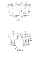
Fig. 1 is an isometric front view of a shoulder mounted hood cooling assembly embodying the features of my invention; -
Fig. 2 is an isometric front view of the assembly ofFig. 1 shown in an open position; -
Fig. 3 is a front view of the assembly shown inFig. 1 ; -
Fig. 4 is a back view of the assembly shown inFig. 1 ; -
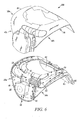
Fig. 5 is an isometric front view of the assembly shown inFig. 1 with an upper shell removed to show the internal passages and ducts formed in the support of the assembly; the dashed lines show air flow in and out of the support; -
Fig. 6 is a back isometric view of the structure shown inFig. 5 ; the dashed lines show airflow in and out of the support; -
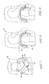
Fig. 7 is a front isometric view of the assembly as worn by a person when the users is wearing an arc protection hood; -
Fig. 8 is a side view of the person inFig. 7 wearing the assembly and hood; the assembly has its abutment in the locked position; -
Fig. 9 is the same side view shown inFig. 8 except the abutment has been deployed; -
Figs. 10a and 10b show an alternative embodiment of a shoulder mounted hood cooling assembly embodying my invention; -
Figs. 11 a and 11b are of a third embodiment of my invention showing a shoulder mounted hood cooling assembly with vent tubes to direct air around a users head; -
Fig. 12 is a fourth embodiment of my invention showing a shoulder mounted hood cooling assembly with a horizontal torso strap. -
Fig. 13 is a fifth embodiment of my invention showing a shoulder mounted assembly; the assembly has the blower mounted to a front of the support; -
Figs. 14a and 14b are a sixth embodiment of my invention showing a support with straps carrying a bag at the back; the bag carries a blower assembly; -
Figs. 15a and 15b are a seventh embodiment of my invention showing a support with a blower assembly at its back; the supports back and front are pinned to the user; the front carries a battery and switch for the blower. -
Figs. 1-9 disclose a shoulder mountedhood cooling assembly 20. The assembly includes ablower 22 carried by ablower support 24. Theblower support 24 is adapted to be carried by the shoulders of auser 34 when in use. - The blower support includes two
curved shoulder mounts chest portions chest portions fasteners 36 such as magnets. The chest portions together form a chest mount or plate. - The blower support includes a back portion, mount, or plate extending downward from the shoulder mounts at the back of the support. The back portion is made up of a
first back portion 38a and asecond back portion 38b. The back portion is located adjacent the user's upper back and shoulder blade area when the support is worn by the user. The shoulder mounts 26, 28,chest portions portion side surfaces 40a, 40á; 40b, 40b'; 40c which together define aneck accommodating space 42. A user's neck is in the space when the support is worn by the user. - The
back plate blower 22 itself is in ablower housing 46 which is in the hollow 44. The back plate or portion has aninlet 48 which leads into the hollow 44. The inlet allows air to be drawn into theblower housing 46. The back portion has aninternal passage 50 leading from the hollow which directs air being exhausted from the blower to a system ofinternal ducts 52 formed by the blower support. The ducts lead tovents support base 202 andsupport shell 200.Figs. 5 ,6 show theshell 200 removed from thebase 202. TheFigs. 5 ,6 help show the location of the hollow, passage, ducts and vents. - The support when resting on the shoulder's of a user positions the vents so that a
drape 56 of aprotective hood 58 falls over and beyond the vents. Air exiting the vents is confined by the drape and forced into open space between the hood and the user's neck and head. Thevents 54a in the chest portion's side surfaces direct air at the user's face and front neck. The vent in theback portion 54b directs air at the back neck and back of the head. Thevents 54c in the shoulder mounts direct air to each lateral side of the neck and head. - It is also possible that the blower does not have a housing distinct from the portion of the back plate which forms the hollow. The blower would be mounted within the hollow 44 without its housing. The
back plate inlet 48, hollow 44 andpassage 50 would direct the air to and from the blower. The blower in this case is an impeller. The blower could be any air conveyor such as a rotatary vane, piston, screw or claw. - To facilitate the user's ability to put on the support, the support is hinged. The
hinge 60 joins a first portion of the support to a second portion. The first portion of the support includes first shoulder mount, 26first chest portion 30 extending from the first shoulder mount, and first back portion 3 8 a of the extending from the first shoulder mount. The second portion of the support includessecond shoulder mount 28second chest portion 32 extending from the second shoulder mount andsecond back portion 38b extending from the second shoulder mount. The hinge joins the first and second support portions together at the first 38a and second 38b back portions. - Having the portions hinged together allows a user to separate the
first shoulder mount 26 andfirst chest portion 30 from thesecond shoulder mount 28 andsecond chest portion 32 in the lateral direction. The separation increases the size of the neck accommodating space making it easier for the user to install the support on the user's body. - A
flexible tube 62 joins a first portion of thepassage 50 in thefirst back portion 38a to a second portion of thepassage 50 in thesecond back portion 38b. The tube helps ensure no air leaks from the passage. - To improve fit on a user, the support has
adjustable abutment assemblies 64. Each chest portion, on its internal side, carries anadjustable abutment assembly 64. Theabutment 65 of each assembly is spring loaded so when the spring member is in an uncompressed state, the abutment is spaced a maximum distance from chest portions towards the back portion. - The spring loaded spacing means the abutment will move from back to front of the support depending on the size of a user's chest. A user with a big chest will push the abutment more towards the front than a user with a small chest.
- A lock mechanism allows a user to lock the abutment at the front of the support. The support is constructed so that it retains it shape when not in use. The support is made of material which includes hard plastic. The
external surface 200 of the support andbase 202 are made of hard plastic.Shell 200 is made up of a first seamless monolithic piece of plastic and a second seamless monolithic piece of plastic joined to the first piece withhinge 60.Base 202 is made up of a first seamless piece of monolithic plastic and a second piece of monolithic plastic. Each piece is joined to the other byhinge 60. The hard plastic defines the ducts, passage, and hollow. To maintain its shape the support needs to be at least framed by a hard material such as hard plastic. Padding can line the interior of at least some of thebase 202 for comfort. - One of the chest portions carry a
switch 206 which allows a user to turn the blower on and off. Another of the chest portions carriesbatteries 204 which power the blower. Accordingly, thebatteries 204 and switch 206 are electronically coupled to a motor which powers the blower. A charge port can be disposed on the support. The charge port is electrically coupled to the batteries. - The support can include straps extending from the chest portions and from the back plate. The straps allow a user to further secure the support to their body during use.
-
Figs. 10a, 10b; 11a, 11b ;12; and 13 show more basic examples of a shoulder mounted hood cooling assembly. All of the supports shown in these figures have shoulder mounts 70chest portions 72 and aback portion 74. These features are clearly shown inFigs. 10a and 10b . The supports do not have an internal hollow housing the blower or a system of internal ducts with vents to direct air to the user's neck and head. - The
support 76 inFigs. 10a, 10b carries a blower andblower housing 78 at the support's back portion. The housing hasvents 80 to direct air to the back of the neck. - The
support 82 inFigs. 11 a, 11b carries a blower andblower housing 86 at its back portion withvent tubes 84 extending from the blower housing to direct air around a user's head. - The
support 90 ofFig. 12 includes ahorizontal torso strap 88 to help secure the support to the user. Thesupport 90 carries the blower andblower housing 92 at its back portion. -
Fig. 13 shows asupport 94 which carries a blower andblower housing 96 at the supports front portion. -
Figs. 14a, 14b show a support with twoshoulder straps 98 carrying abag 100 at the back. The back carries a blower assembly. Each of the two straps include first and second strap portions which are fastened together by fasteners such aVelcro 104. -
Figs. 15a, 15b show a fabriccrushable support 106 carrying ablower assembly 112 at its back portion. Theback portion 108 is pinned to a user's clothing. The shoulder mounts 110 extend from the back portion and are pinned to the user's clothing. - The term user encompasses an adult male or female around the age of 40 with an average build.
- Attention is directed to all papers and documents which are filed concurrently with or previous to this specification in connection with this application and which are open to public inspection with this specification, and the contents of all such papers and documents are incorporated herein by reference.
- All of the features disclosed in this specification (including any accompanying claims, abstract and drawings), and/or all of the steps of any method or process so disclosed, may be combined in any combination, except combinations where at least some of such features and/or steps are mutually exclusive.
- Each feature disclosed in this specification (including any accompanying claims, abstract and drawings) may be replaced by alternative features serving the same, equivalent or similar purpose, unless expressly stated otherwise. Thus, unless expressly stated otherwise, each feature disclosed is one example only of a generic series of equivalent or similar features.
- The invention is not restricted to the details of the foregoing embodiment(s). The invention extends to any novel one, or any novel combination, of the features disclosed in this specification (including any accompanying claims, abstract and drawings), or to any novel one, or any novel combination, of the steps of any method or process so disclosed.
- Although an example of the invention has been disclosed, it will be appreciated by those skilled in the art that various changes and modifications might be made without departing from the spirit and scope of the invention.
Claims (15)
- A shoulder mounted hood cooling assembly comprising:a support;a blower carried by said support;a first curved shoulder mount forming a portion of said support, said first shoulder mount defining an inwardly facing side surface;a second curved shoulder mount forming a portion of said support, said second shoulder mount defining a inwardly facing side surface;a first chest portion extending downward from said first curved shoulder support and at a front of said support, said first chest portion defining an inwardly facing side surface;a second chest portion extending downward from second said curved shoulder mount and at a front of said support, said second chest portion defining an inwardly facing side surface;a back portion extending downward from said first and second shoulder mounts at the back of the support, said back portion defining an inwardly facing side surface;a neck accommodating space defmed by said inwardly facing side surfaces;a vent in fluid communication with said blower;wherein when said support is worn by a user, the shoulder mounts rest on top of the user's shoulders and the support positions the vent to direct air exhausted from the blower at a neck or a head or both the neck or head of the user.
- The shoulder mounted cooling assembly of claim 1 wherein said vent opens through one of said side surfaces.
- The shoulder mounted cooling assembly of claim 2 further comprising:an internal passage formed within said support, said passage in fluid communication with said blower and said vent.
- The shoulder mounted hood cooling assembly of claim 3 further comprising:an internal hollow formed in said back portion, said blower in said hollow.
- The shoulder mounted hood cooling assembly of claim 4 wherein said passage is in fluid communication with said hollow.
- The shoulder mounted hood cooling assembly of claim 5 wherein said blower itself is in a housing distinct from said support.
- The shoulder mounted hood cooling assembly of claim 1 further comprising:a hinge joining a first portion of the support to a second portion of the support.
- The shoulder mounted hood cooling assembly of claim 7 wherein said first portion of the support includes said first shoulder mount, said first chest portion and a first portion of said back portion and wherein said second portion of the support includes said second shoulder mount, said second chest portion and a second back portion of said back portion.
- The shoulder mounted hood cooling assembly of claim 8 wherein said hinge joins the first and second support portions together at the first and second back portions.
- The shoulder mounted hood cooling assembly of claim 1 further comprising an adjustable abutment assembly on a internal side of said first chest portion, said abutment assembly having an abutment movable from back to front and from front to back of the support.
- The shoulder mounted hood cooling assembly of claim 9 having a lock mechanism to lock the abutment assembly so the abutment will be locked in a position at the front of the support.
- The shoulder mounted hood cooling assembly of claim 1 wherein at least said first shoulder mount, first chest portion and a portion of said back portion are made from a seamless monothilic shell coupled to a seamless monothilic base.
- The shoulder mounted hood cooling assembly of claim 12 wherein said portion formed by said shell and said base have a duct formed therein; and
wherein said vent is formed in said shell and base and is in fluid communication said duct and said duct is in fluid communication with said blower. - A shoulder mounted hood cooling assembly comprising:a support;a blower carried by said support;vents in fluid communication with said blower;a worn position wherein when in said worn position at least a portion of said support is adjacent a user's shoulders and the support positions the vent to direct air exhausted from the blower to a neck or to a head or both the neck and the head of a user.
- The shoulder mounted hood cooling assembly of claim 13 wherein said support comprises a first shoulder strap and a second shoulder strap.
Applications Claiming Priority (1)
| Application Number | Priority Date | Filing Date | Title |
|---|---|---|---|
| US12/790,397 US8230852B2 (en) | 2010-05-28 | 2010-05-28 | Shoulder mounted hood cooling system |
Publications (1)
| Publication Number | Publication Date |
|---|---|
| EP2389984A1 true EP2389984A1 (en) | 2011-11-30 |
Family
ID=44117820
Family Applications (1)
| Application Number | Title | Priority Date | Filing Date |
|---|---|---|---|
| EP11166615A Withdrawn EP2389984A1 (en) | 2010-05-28 | 2011-05-18 | Shoulder mounted hood cooling system |
Country Status (3)
| Country | Link |
|---|---|
| US (1) | US8230852B2 (en) |
| EP (1) | EP2389984A1 (en) |
| CA (1) | CA2740517A1 (en) |
Cited By (1)
| Publication number | Priority date | Publication date | Assignee | Title |
|---|---|---|---|---|
| GB2598157A (en) * | 2020-08-21 | 2022-02-23 | Manchester Univ Nhs Foundation Trust | Respirator |
Families Citing this family (17)
| Publication number | Priority date | Publication date | Assignee | Title |
|---|---|---|---|---|
| US9480290B2 (en) | 2011-03-22 | 2016-11-01 | Medline Industries, Inc. | Protective apparel and support apparatus and method of use |
| AU2012230853B2 (en) | 2011-03-22 | 2015-09-03 | Medline Industries, Lp | Protective apparel and support apparatus |
| US10448685B2 (en) | 2011-03-22 | 2019-10-22 | Medline Industries, Inc. | Protective apparel and support apparatus and method of use |
| US11493998B2 (en) | 2012-01-17 | 2022-11-08 | Ultrahaptics IP Two Limited | Systems and methods for machine control |
| GB2523049B (en) * | 2012-11-30 | 2017-08-02 | Koken Kk | Air blower and protective suit including the same |
| AU2013260673A1 (en) * | 2012-12-10 | 2014-06-26 | Medline Industries, Inc. | Protective Apparel and SUpport Apparatus and Method of Use |
| US10241639B2 (en) | 2013-01-15 | 2019-03-26 | Leap Motion, Inc. | Dynamic user interactions for display control and manipulation of display objects |
| US10620709B2 (en) | 2013-04-05 | 2020-04-14 | Ultrahaptics IP Two Limited | Customized gesture interpretation |
| US9436288B2 (en) | 2013-05-17 | 2016-09-06 | Leap Motion, Inc. | Cursor mode switching |
| US10620775B2 (en) | 2013-05-17 | 2020-04-14 | Ultrahaptics IP Two Limited | Dynamic interactive objects |
| US9747696B2 (en) | 2013-05-17 | 2017-08-29 | Leap Motion, Inc. | Systems and methods for providing normalized parameters of motions of objects in three-dimensional space |
| US9795758B2 (en) | 2013-06-25 | 2017-10-24 | Breathe Technologies, Inc. | Ventilator with integrated cooling system |
| US10470505B2 (en) * | 2014-05-07 | 2019-11-12 | Medline Industries, Inc. | Protective apparel system with impervious protection |
| US9861152B1 (en) * | 2014-11-05 | 2018-01-09 | Robert Rumfelt | Method and apparatus for improved helmet |
| WO2016159889A1 (en) | 2015-04-02 | 2016-10-06 | Hill-Rom Services Pte. Ltd. | Manifold for respiratory device |
| US11875012B2 (en) | 2018-05-25 | 2024-01-16 | Ultrahaptics IP Two Limited | Throwable interface for augmented reality and virtual reality environments |
| FR3108479A1 (en) * | 2020-03-27 | 2021-10-01 | Abyssnaut | Full face protection helmet |
Citations (6)
| Publication number | Priority date | Publication date | Assignee | Title |
|---|---|---|---|---|
| CH556664A (en) * | 1972-10-19 | 1974-12-13 | Mathys Robert | Face-masks for use in operating-theatres - is partly transparent, ventilated by battery driven fan and coupled to filter unit |
| EP0490347A1 (en) * | 1990-12-12 | 1992-06-17 | F.I.M.A.C. Fabbrica Italiana Macchine Aria Compressa S.p.A. | Cooling garment, particularly of the jacket type or the like |
| EP0791301A2 (en) * | 1996-02-21 | 1997-08-27 | Surgical Specialty Products, Inc. | Surgical suit |
| US20070163600A1 (en) * | 2006-01-11 | 2007-07-19 | Leslie Hoffman | User interface and head gear for a continuous positive airway pressure device |
| US7357135B2 (en) | 2004-09-08 | 2008-04-15 | Steel Grip, Inc. | Protective hood with fan assembly |
| US20080295220A1 (en) | 2007-05-31 | 2008-12-04 | Webb Nicholas J | Fan-Based Cooler for Head-Protection Gear |
Family Cites Families (11)
| Publication number | Priority date | Publication date | Assignee | Title |
|---|---|---|---|---|
| US1360A (en) * | 1839-10-09 | Improvement in plows | ||
| US2171337A (en) * | 1938-10-17 | 1939-08-29 | Hellmann John | Air conditioned garment |
| US3049896A (en) * | 1960-04-27 | 1962-08-21 | Environment Inc | Personnel isolation and protection systems |
| US3525334A (en) * | 1966-04-07 | 1970-08-25 | Richard J Braman | Garment assembly |
| US4019508A (en) * | 1976-05-21 | 1977-04-26 | Research Development Systems, Inc. | Wearable, self-contained fully mobile personal breathing apparatus for surgeons and operating room personnel |
| US4158242A (en) * | 1977-06-06 | 1979-06-19 | A-T-O Inc. | Shoulder pad |
| FR2673380B1 (en) * | 1991-02-28 | 1993-06-18 | Intertechnique Sa | PERSONAL RESPIRATORY PROTECTION EQUIPMENT. |
| USH1360H (en) * | 1991-04-24 | 1994-10-04 | The United States Of America, As Represented By The Secretary Of The Army | Lightweight protective gas mask and hood |
| DE29909732U1 (en) * | 1999-06-04 | 1999-09-09 | Draeger Sicherheitstech Gmbh | Carrying device for a breathing apparatus |
| US7832396B2 (en) * | 2005-06-10 | 2010-11-16 | Radium Incorporated | High air flow powered air purifying anti-contamination device |
| US7516743B2 (en) * | 2006-04-20 | 2009-04-14 | Viasys Sleep Systems, Llc | Continuous positive airway pressure device and configuration for employing same |
-
2010
- 2010-05-28 US US12/790,397 patent/US8230852B2/en active Active
-
2011
- 2011-05-18 EP EP11166615A patent/EP2389984A1/en not_active Withdrawn
- 2011-05-19 CA CA2740517A patent/CA2740517A1/en not_active Abandoned
Patent Citations (6)
| Publication number | Priority date | Publication date | Assignee | Title |
|---|---|---|---|---|
| CH556664A (en) * | 1972-10-19 | 1974-12-13 | Mathys Robert | Face-masks for use in operating-theatres - is partly transparent, ventilated by battery driven fan and coupled to filter unit |
| EP0490347A1 (en) * | 1990-12-12 | 1992-06-17 | F.I.M.A.C. Fabbrica Italiana Macchine Aria Compressa S.p.A. | Cooling garment, particularly of the jacket type or the like |
| EP0791301A2 (en) * | 1996-02-21 | 1997-08-27 | Surgical Specialty Products, Inc. | Surgical suit |
| US7357135B2 (en) | 2004-09-08 | 2008-04-15 | Steel Grip, Inc. | Protective hood with fan assembly |
| US20070163600A1 (en) * | 2006-01-11 | 2007-07-19 | Leslie Hoffman | User interface and head gear for a continuous positive airway pressure device |
| US20080295220A1 (en) | 2007-05-31 | 2008-12-04 | Webb Nicholas J | Fan-Based Cooler for Head-Protection Gear |
Cited By (1)
| Publication number | Priority date | Publication date | Assignee | Title |
|---|---|---|---|---|
| GB2598157A (en) * | 2020-08-21 | 2022-02-23 | Manchester Univ Nhs Foundation Trust | Respirator |
Also Published As
| Publication number | Publication date |
|---|---|
| US8230852B2 (en) | 2012-07-31 |
| CA2740517A1 (en) | 2011-11-28 |
| US20110289954A1 (en) | 2011-12-01 |
Similar Documents
| Publication | Publication Date | Title |
|---|---|---|
| EP2389984A1 (en) | Shoulder mounted hood cooling system | |
| US8082596B2 (en) | Garment for personal air-conditioning | |
| JP6766288B2 (en) | clothes | |
| JP6233674B1 (en) | Cooling clothing | |
| US7357135B2 (en) | Protective hood with fan assembly | |
| JP6908910B2 (en) | Garment and cooling system | |
| WO2020090483A1 (en) | Garment | |
| JP2007524436A (en) | Rigid air duct for respiratory hood and helmet | |
| US20130160195A1 (en) | Portable fan and battery box for clearing fog/particles in goggles or for cooling masks and helmets | |
| WO2013181398A2 (en) | Cooling unit | |
| JP6078937B1 (en) | Cooling clothing | |
| JP2020070502A5 (en) | ||
| JP6963802B2 (en) | Rucksack type human body blower | |
| JP2018009264A (en) | Cooling garment | |
| US20230404184A1 (en) | Air blowing device and air-conditioned clothing | |
| JP3217144U (en) | Cooling clothing | |
| JP7122150B2 (en) | Push units for push-pull ventilators and push-pull ventilators | |
| JP2021066985A (en) | Clothing with fan holder | |
| JP2012180606A (en) | Helmet having ventilating function | |
| JP2017040017A (en) | Fan device for human body | |
| CN112703095B (en) | Human robot | |
| CN212911911U (en) | Protective helmet | |
| JP6955772B2 (en) | Clothes body and clothes | |
| WO2021221037A1 (en) | Garment body for fan-equipped garment, and fan-equipped garment | |
| CN203435771U (en) | Protective helmet |
Legal Events
| Date | Code | Title | Description |
|---|---|---|---|
| 17P | Request for examination filed |
Effective date: 20110518 |
|
| AK | Designated contracting states |
Kind code of ref document: A1 Designated state(s): AL AT BE BG CH CY CZ DE DK EE ES FI FR GB GR HR HU IE IS IT LI LT LU LV MC MK MT NL NO PL PT RO RS SE SI SK SM TR |
|
| AX | Request for extension of the european patent |
Extension state: BA ME |
|
| PUAI | Public reference made under article 153(3) epc to a published international application that has entered the european phase |
Free format text: ORIGINAL CODE: 0009012 |
|
| RAP1 | Party data changed (applicant data changed or rights of an application transferred) |
Owner name: HONEYWELL INTERNATIONAL INC. |
|
| 17Q | First examination report despatched |
Effective date: 20180508 |
|
| GRAP | Despatch of communication of intention to grant a patent |
Free format text: ORIGINAL CODE: EPIDOSNIGR1 |
|
| INTG | Intention to grant announced |
Effective date: 20181221 |
|
| STAA | Information on the status of an ep patent application or granted ep patent |
Free format text: STATUS: THE APPLICATION IS DEEMED TO BE WITHDRAWN |
|
| 18D | Application deemed to be withdrawn |
Effective date: 20190501 |