EP2398102A1 - Fuel cell - Google Patents
Fuel cell Download PDFInfo
- Publication number
- EP2398102A1 EP2398102A1 EP11169769A EP11169769A EP2398102A1 EP 2398102 A1 EP2398102 A1 EP 2398102A1 EP 11169769 A EP11169769 A EP 11169769A EP 11169769 A EP11169769 A EP 11169769A EP 2398102 A1 EP2398102 A1 EP 2398102A1
- Authority
- EP
- European Patent Office
- Prior art keywords
- layer
- barrier layer
- buffer
- barrier
- fuel cell
- Prior art date
- Legal status (The legal status is an assumption and is not a legal conclusion. Google has not performed a legal analysis and makes no representation as to the accuracy of the status listed.)
- Granted
Links
Images


Classifications
-
- H—ELECTRICITY
- H01—ELECTRIC ELEMENTS
- H01M—PROCESSES OR MEANS, e.g. BATTERIES, FOR THE DIRECT CONVERSION OF CHEMICAL ENERGY INTO ELECTRICAL ENERGY
- H01M4/00—Electrodes
- H01M4/86—Inert electrodes with catalytic activity, e.g. for fuel cells
- H01M4/8647—Inert electrodes with catalytic activity, e.g. for fuel cells consisting of more than one material, e.g. consisting of composites
- H01M4/8657—Inert electrodes with catalytic activity, e.g. for fuel cells consisting of more than one material, e.g. consisting of composites layered
-
- H—ELECTRICITY
- H01—ELECTRIC ELEMENTS
- H01M—PROCESSES OR MEANS, e.g. BATTERIES, FOR THE DIRECT CONVERSION OF CHEMICAL ENERGY INTO ELECTRICAL ENERGY
- H01M4/00—Electrodes
- H01M4/86—Inert electrodes with catalytic activity, e.g. for fuel cells
- H01M4/88—Processes of manufacture
- H01M4/8878—Treatment steps after deposition of the catalytic active composition or after shaping of the electrode being free-standing body
- H01M4/8882—Heat treatment, e.g. drying, baking
- H01M4/8885—Sintering or firing
-
- H—ELECTRICITY
- H01—ELECTRIC ELEMENTS
- H01M—PROCESSES OR MEANS, e.g. BATTERIES, FOR THE DIRECT CONVERSION OF CHEMICAL ENERGY INTO ELECTRICAL ENERGY
- H01M4/00—Electrodes
- H01M4/86—Inert electrodes with catalytic activity, e.g. for fuel cells
- H01M4/90—Selection of catalytic material
- H01M4/9016—Oxides, hydroxides or oxygenated metallic salts
-
- H—ELECTRICITY
- H01—ELECTRIC ELEMENTS
- H01M—PROCESSES OR MEANS, e.g. BATTERIES, FOR THE DIRECT CONVERSION OF CHEMICAL ENERGY INTO ELECTRICAL ENERGY
- H01M8/00—Fuel cells; Manufacture thereof
- H01M8/10—Fuel cells with solid electrolytes
- H01M8/12—Fuel cells with solid electrolytes operating at high temperature, e.g. with stabilised ZrO2 electrolyte
- H01M8/1213—Fuel cells with solid electrolytes operating at high temperature, e.g. with stabilised ZrO2 electrolyte characterised by the electrode/electrolyte combination or the supporting material
-
- H—ELECTRICITY
- H01—ELECTRIC ELEMENTS
- H01M—PROCESSES OR MEANS, e.g. BATTERIES, FOR THE DIRECT CONVERSION OF CHEMICAL ENERGY INTO ELECTRICAL ENERGY
- H01M8/00—Fuel cells; Manufacture thereof
- H01M8/10—Fuel cells with solid electrolytes
- H01M8/12—Fuel cells with solid electrolytes operating at high temperature, e.g. with stabilised ZrO2 electrolyte
- H01M8/124—Fuel cells with solid electrolytes operating at high temperature, e.g. with stabilised ZrO2 electrolyte characterised by the process of manufacturing or by the material of the electrolyte
- H01M8/1246—Fuel cells with solid electrolytes operating at high temperature, e.g. with stabilised ZrO2 electrolyte characterised by the process of manufacturing or by the material of the electrolyte the electrolyte consisting of oxides
- H01M8/1253—Fuel cells with solid electrolytes operating at high temperature, e.g. with stabilised ZrO2 electrolyte characterised by the process of manufacturing or by the material of the electrolyte the electrolyte consisting of oxides the electrolyte containing zirconium oxide
-
- H—ELECTRICITY
- H01—ELECTRIC ELEMENTS
- H01M—PROCESSES OR MEANS, e.g. BATTERIES, FOR THE DIRECT CONVERSION OF CHEMICAL ENERGY INTO ELECTRICAL ENERGY
- H01M8/00—Fuel cells; Manufacture thereof
- H01M8/10—Fuel cells with solid electrolytes
- H01M8/12—Fuel cells with solid electrolytes operating at high temperature, e.g. with stabilised ZrO2 electrolyte
- H01M2008/1293—Fuel cells with solid oxide electrolytes
-
- Y—GENERAL TAGGING OF NEW TECHNOLOGICAL DEVELOPMENTS; GENERAL TAGGING OF CROSS-SECTIONAL TECHNOLOGIES SPANNING OVER SEVERAL SECTIONS OF THE IPC; TECHNICAL SUBJECTS COVERED BY FORMER USPC CROSS-REFERENCE ART COLLECTIONS [XRACs] AND DIGESTS
- Y02—TECHNOLOGIES OR APPLICATIONS FOR MITIGATION OR ADAPTATION AGAINST CLIMATE CHANGE
- Y02E—REDUCTION OF GREENHOUSE GAS [GHG] EMISSIONS, RELATED TO ENERGY GENERATION, TRANSMISSION OR DISTRIBUTION
- Y02E60/00—Enabling technologies; Technologies with a potential or indirect contribution to GHG emissions mitigation
- Y02E60/30—Hydrogen technology
- Y02E60/50—Fuel cells
-
- Y—GENERAL TAGGING OF NEW TECHNOLOGICAL DEVELOPMENTS; GENERAL TAGGING OF CROSS-SECTIONAL TECHNOLOGIES SPANNING OVER SEVERAL SECTIONS OF THE IPC; TECHNICAL SUBJECTS COVERED BY FORMER USPC CROSS-REFERENCE ART COLLECTIONS [XRACs] AND DIGESTS
- Y02—TECHNOLOGIES OR APPLICATIONS FOR MITIGATION OR ADAPTATION AGAINST CLIMATE CHANGE
- Y02P—CLIMATE CHANGE MITIGATION TECHNOLOGIES IN THE PRODUCTION OR PROCESSING OF GOODS
- Y02P70/00—Climate change mitigation technologies in the production process for final industrial or consumer products
- Y02P70/50—Manufacturing or production processes characterised by the final manufactured product
Definitions
- the present invention relates to a fuel cell, and in particular, relates to a solid-oxide fuel cell.
- Patent Literature 1 discloses a fuel cell stack that includes a solid electrolyte layer, and an anode and a cathode that are opposed through the solid electrolyte layer.
- a fuel cell that includes at least two layers having a different composition is associated with the disadvantage that the coefficient of thermal expansion and/or the firing contraction amount in the respective layers differs in response to heat produced during manufacture and/or use. More specifically, this disadvantage includes the production of a crack in one of the layers and peeling of one layer from the other layer as a result of a distortion caused by thermal stress.
- the present invention is proposed in light of the above problems, and has the object of suppressing the production of such a disadvantage in a fuel cell.
- a fuel cell includes an anode, a cathode, a solid electrolyte layer, a barrier layer, and an buffer layer.
- the solid electrolyte layer includes zirconium and is provided between the anode and the cathode.
- the barrier layer includes cerium and is provided between the solid electrolyte layer and the cathode.
- the barrier layer has pores.
- the buffer layer includes zirconium and cerium and is provided between the barrier layer and the solid electrolyte layer.
- the barrier layer has a first barrier layer provided near to the buffer layer with a first pore ratio and a second barrier layer provided between the first barrier layer and the cathode with a second pore ratio. The first pore ratio of the first barrier layer is larger than the second pore ratio of the second barrier layer.
- the fuel cell according to the present invention has a barrier layer that includes pores, heat stress between the barrier layer and the solid electrolyte layer is reduced, and the attachment strength between the barrier layer and the solid electrolyte layer is increased by the buffer layer to thereby suppress peeling between the barrier layer and the solid electrolyte layer.
- a solid oxide fuel cell is an example of a fuel cell.
- the following description mainly relates to a SOFC that includes a cell-stack structure in which a plurality of fuel cells is stacked.
- a fuel cell stack 10 includes a fuel cell (simply termed a "cell") 1 and a current collecting member 4.
- the fuel cell stack 10 is a vertically-striped fuel cell, the present invention can also be applied to configurations other than a segmented-in-series configuration as described below.
- a plurality of cells 1 in the fuel cell stack 10 is stacked in the y-axis direction through the current collecting member 4. That is to say, the fuel cell stack 10 includes a plurality of stacked cells 1.
- the cell 1 is a thin ceramic plate.
- the thickness of the cell 1 is for example 30 ⁇ m to 300 ⁇ m, and the diameter of the cell 1 is for example 5 mm to 50 mm.
- the cell 1 as illustrated in FIG. 1 includes an anode 11, a barrier layer 13, a cathode 14, an electrolyte layer 15, and an buffer layer 16.
- the electrolyte layer 15 is disposed between the anode 11 and the cathode 14.
- the barrier layer 13 is disposed between the electrolyte layer 15 and the cathode 14.
- the buffer layer 16 is disposed between the electrolyte layer 15 and the barrier layer 13.
- the buffer layer 16 makes contact with the electrolyte layer 15, and the buffer layer 16 makes contact with the barrier layer 13.
- the interface between the barrier layer 13 and the buffer layer 16 is termed a barrier-buffer interface layer 17, and the interface between the electrolyte layer 15 and the buffer layer 16 is termed an buffer-electrolyte interface layer 18.
- the material used in the anode 11 for example includes a material used in the anode in a known fuel cell. More specifically, the material used in the anode 11 may include NiO - YSZ (nickel oxide - yttria-stabilized zirconia) and/or NiO-Y 2 O 3 (nickel oxide - yttria).
- the anode 11 may include these materials as a main component.
- the anode 11 may function as a base plate (in other words, a support body) that supports the other layers included in the cell 1. That is to say, the thickness of the anode 11 may represent the maximum thickness in the plurality of layers contained in the cell 1. More specifically, the thickness of the anode 11 is of the order of 10 ⁇ m to 300 ⁇ m.
- the anode 11 can be imparted conductive properties by application of a reduction treatment (for example, a treatment of reducing NiO to Ni).
- composition A includes material B as a main component
- composition A preferably means that the content of material B in composition A is at least 60 wt%, and still more preferably, means that the content of material B in composition A is at least 70wt%.
- the anode 11 may include at least two layers.
- the anode 11 may have two layers, that is to say, a base plate and an anode-active layer (fuel side electrode) formed thereon.
- the material in the base plate and the anode-active layer may be selected from the materials for the anode 11 as described above. More specifically, a combination may be used in which the base plate is formed from NiO-Y 2 O 3 and the anode-active layer is formed from NiO -YSZ.
- the barrier layer 13 includes cerium.
- the barrier layer may include cerium in the form of ceria (cerium oxide). More specifically, materials that are used in the barrier layer 13 include ceria and ceria-based materials including rare-earth metal oxides configured as a solid solution into ceria.
- the barrier layer 13 may include a ceria-based material as a main component. More specifically, the ceria-based material includes GDC ((Ce, Gd)O 2 : gadolinium doped ceria), SDC ((Ce, Sm)O 2 : samarium doped ceria). For example, the mol composition ratio of the rare earth metal oxide to ceria may be 5 to 95 - 20 to 80.
- the barrier layer 13 may include additives in addition to a ceria-based material.
- the thickness of the barrier layer 13 for example may be 40 ⁇ m or less, may be 30 ⁇ m or less, or may be 20 ⁇ m or less.
- the barrier layer 13 suppresses formation of a high resistance layer by suppressing the diffusion of cations from the cathode 14 into the electrolyte layer 15. As a result, the barrier layer 13 enables suppression of a reduction in the output density, and increases the product life of the cell 1.
- the barrier layer 13 includes a first barrier layer 131 and a second barrier layer 132.
- the first barrier layer 131 includes pores, and is present in a range within 2.0 pm from the barrier-buffer interface 17.
- the region from the barrier-buffer interface 17 to the intermediate surface 13a corresponds to the first barrier layer 131, and the distance from the barrier-buffer interface 17 to the intermediate surface 13a is no more than 2.0 ⁇ m. That is to say, in the present embodiment, the thickness of the first barrier layer 131 is no more than 2.0 ⁇ m.
- the first barrier layer 131 includes a plurality of pores 13c.
- the shape of the pores 13c there is no limitation on the shape of the pores 13c, and the cross sectional shape of the pores 13c may be substantially oval (including circular).
- the major-axis diameter R of the pore 13c preferably satisfies the relationship R ⁇ 1 ⁇ m, and the major-axis diameter R preferably satisfies the relationship 0.05 ⁇ m ⁇ R.
- the pores 13c may be closed pores. Furthermore all of the pores 13c contained in the first barrier layer 131 may be closed pores.
- the closed pores may be disposed in the cell 1, that is to say, in the first barrier layer 131, and the inner portion of the closed pores may be isolated from the outer air of the cell 1.
- the inclusion of closed pores in the first barrier layer 131 enables the first barrier layer 131 to exhibit an effect that substantially mitigates the distortion, that is to say, an effect that substantially mitigates thermal stress. Furthermore, even when a crack is generated in the barrier layer 13, the inclusion of closed pores suppresses increase in crack width.
- the second barrier layer 132 may include pores, and at least a portion of the pores may be closed pores.
- the pore ratio P1 of the first barrier layer 131 preferably satisfies the relationship P1 ⁇ 15%, and the pore ratio P1 preferably satisfies the relationship 1% ⁇ P1.
- the pore ratio may be expressed as a space ratio.
- the pore ratio P1 is expressed by the ratio of the volume V2 of the space (including the pores 13c) with respect to the total volume V1 of the first barrier layer 131 (V2/V1), it may be expressed as the surface area of the pores 13c per unit area in cross section of the first barrier layer.
- the pore ratio P for example is acquired by
- the number of pores per 10 ⁇ m length with respect to a direction that is parallel to the interface direction between layers in a cross section that is parallel to the thickness direction of the first barrier layer 131 is preferably 5 or less.
- the coefficient of thermal expansion and firing contraction amount of the barrier layer 13 is different from the coefficient of thermal expansion and firing contraction amount of the electrolyte layer 15. Since the barrier layer 13 and the electrolyte layer 15 are fired in a stacked configuration during manufacture of the cell 1, a distortion is formed in an inner portion of the barrier layer 13 and the electrolyte layer 15. The cell 1 is then subjected to a high temperature during operation, and returns to an ambient temperature during a non-operational period.
- the a barrier 13 that includes a first barrier layer 131 that has pores 13c mitigates the stress, and suppresses peeling.
- the first barrier layer 131 may contain zirconium.
- the average content amount of zirconium in the first barrier layer 131 (that is to say, the concentration of zirconium) is preferably lower than the average content amount of cerium (that is to say, the concentration of cerium). More specifically, "concentration” as used herein is a value that is obtained by line analysis based on an atomic concentration profile as described hereafter.
- the second barrier layer 132 is disposed between the first barrier layer 131 and the cathode 14. More specifically, the second barrier layer 132 occupies the area from the intermediate surface 13a that is the upper surface of the first barrier layer 131 to the upper surface of the barrier layer 13 (in FIG. 1 , the interface 13b between the barrier layer 13 and the cathode 14).
- the pore ratio P2 of the second barrier layer 132 is preferably lower than the pore ratio P1 of the first barrier layer 131. More specifically, the pore ratio P2 of the second barrier layer 132 preferably satisfies the relationship P2 ⁇ 10%.
- the ratio of the pore ratio P2 of the second barrier layer 132 to the pore ratio P1 of the first barrier layer 131 preferably satisfies the relationship P2/P1 ⁇ 0.7.
- the average value of the major-axis diameter of the pores contained in the second barrier layer 132 is preferably smaller than the average value of the major-axis diameter of the pores 13c contained in the first barrier layer 131.
- the effect of suppressing cation diffusion by the second barrier layer 132 is enhanced by configuring the pore ratio of the second barrier layer 132 to take a small value, and/or making the pores in the second barrier layer 132 small. Furthermore the electrical resistance value of the cell 1 is suppressed to a low value by providing the second barrier layer 132 in a dense configuration.
- the pore ratio of the second barrier layer 132 is calculated in the same manner as the pore ratio of the first barrier layer 131.
- a cathode material for a known fuel cell is used as the material of the cathode 14. More specifically, the material in the cathode 14 includes LSCF (lanthanum strontium cobalt ferrite: (LaSr)(CoFe)O 3 ).
- the composition of LSCF for example includes La 0.6 Sr 0 . 4 Co 0.2 Fe 0.8 O 3 .
- the cathode 14 may include the above materials as a main component.
- the thickness of the cathode 14 may be of the order of 5 ⁇ m - 50 ⁇ m.
- the electrolyte layer 15 is an example of a solid electrolyte layer, and contains zirconium.
- the electrolyte layer 15 may include zirconium in the form of zirconia (ZrO 2 ). More specifically, the electrolyte layer 15 may include zirconia as a main component.
- the electrolyte layer 15 may include an additive such as Y 2 O 3 and/or Sc 2 O 3 in addition to zirconia. These additives may function as a stabilizer. In the electrolyte layer 15, the stabilizer may have a mol composition ratio with respect to zirconia of 3:97 - 20:80.
- the material used in the electrolyte layer 15 includes zirconia-based materials such as yttria-stabilized zirconia including 3YSZ, 8YSZ, and 10YSZ, and ScSZ (scandia-stablized zirconia) or the like.
- the thickness of the electrolyte layer 15 may be 30 ⁇ m or less.
- the pore ratio of the electrolyte layer 15 is preferably less than the pore ratio of the first barrier layer 131, and preferably less than the pore ratio of the second barrier layer 132. More specifically, the pore ratio of the electrolyte layer 15 may be no more than 7%, or no more than 5%, or no more than 3%. The pore ratio of the electrolyte layer 15 is calculated in the same manner as the pore ratio of the first barrier layer 131 as described above.
- the buffer layer 16 includes zirconium and cerium.
- the zirconium and cerium may be in the form of ceria and zirconia, and may be included in the buffer layer 16.
- the zirconium (or zirconia) and cerium (or ceria) in the buffer layer 16 may be mixed, and the buffer layer 16 is preferably a solid solution of ceria and zirconia.
- the buffer layer 16 may include a material other than cerium and zirconium.
- the buffer layer 16 may include for example a material (additive or the like) that is included in the barrier layer 13 or the electrolyte layer 15. When the electrolyte layer 15 contains yttrium (Y), the buffer layer 16 also contains yttrium.
- the buffer layer 16 also contains gadolinium.
- the buffer layer 16 increases the attachment strength between the barrier layer 13 and the electrolyte layer 15 and suppresses peeling.
- the barrier layer 13, the electrolyte layer 15, and the buffer layer 16 may be co-fired.
- the cerium concentration D1 and the zirconium concentration D2 may satisfy (1) to (8) below.
- any one of the conditions in conditions (1) to (8) may be satisfied, or two or more conditions may be satisfied.
- concentration in the each overall layer that is to say, the average content amount of a component (for example, zirconium or cerium and so on) in each layer.
- concentration is obtained by line analysis using a atomic concentration profile, that is to say, it is obtained by a comparison between the characteristic X-ray intensity using an EPMA (electron probe micro analyzer).
- EPMA electron probe micro analyzer
- EPMA Quantitative analysis using EPMA is known to a person skilled in the art.
- EPMA is an apparatus that detects and identifies the component elements in a minute region (approximately 1 ⁇ m 3 ) onto which an electron beam is illuminated based on the characteristic X-ray spectrum that is irradiated by illumination of an electron beam onto a target object, and then analyzes the ratio (concentration) of each component element.
- Quantitative analysis using EPMA is executed by comparison of the characteristic X-ray intensity of a reference test material that has a clear element concentration and a characteristic X-ray intensity of an unknown test material.
- concentration distribution data for each element is acquired by line analysis with respect to a thickness dimension (y direction) using EPMA in a cross section that is substantially parallel to the thickness dimension (y axial direction) in the cell 1.
- the concentration D1 - D4 can be determined by element mapping using an EPMA (electron problem micro analyzer).
- EPMA is a concept that includes EDS (energy dispersive x-ray spectroscopy).
- the position of the barrier-buffer interface 17 can be specified as described hereafter with reference to a cross section of a cell 1 that is substantially parallel to the thickness dimension (y axial direction).
- the concentration distribution data for each element can be acquired by executing a line analysis in the layer thickness dimension (y direction) using EPMA in a cross section that is substantially parallel thickness dimension (y direction).
- This concentration distribution data can be used to determine the position of the line that corresponds with the concentration of cerium and the concentration of zirconium as the position of the barrier-buffer interface 17. That is to say, the concentration of zirconium and the concentration of cerium is substantially the same in proximity to the barrier-buffer interface 17.
- the position of the buffer-electrolyte interface 18 is specified as the line position that demonstrates 80% concentration of the maximum concentration of zirconium in the cross section (the maximum zirconium concentration in the electrolyte layer).
- the distribution of the cerium concentration and the zirconium concentration in the buffer layer 16 may satisfy the conditions (a) to (e) below.
- any one of the conditions in conditions (a) to (d) may be satisfied, or two or more conditions may be satisfied. The greater a number of conditions is satisfied, the more it is preferred.
- the cell 1 has a concentration gradient that shows a gradually decreasing cerium concentration and a gradually increasing zirconium concentration from the lower surface of the barrier layer 13 to the upper surface of the electrolyte layer 15.
- the cerium concentration and the zirconium concentration in (a) to (d) above may be a value that is obtained by line analysis using EPMA.
- the thickness of the buffer layer 16, that is to say, the distance from the buffer-electrolyte interface 18 to the barrier-buffer interface 17 is preferably at least 0.5 ⁇ m and preferably no more than 2 ⁇ m.
- the ratio of the pore ratio P3 in the buffer layer 16 relative to the pore ratio P1 in the first barrier layer 131 (P3/P1) is preferably no more than 0.3.
- the coefficient of thermal expansion of the buffer layer 16 (that is to say, the coefficient of linear expansion) is a value between the coefficient of thermal expansion of the electrolyte layer 15 and the coefficient of thermal expansion of the barrier layer 13.
- the coefficient of thermal expansion of the buffer layer 16 when the coefficient of thermal expansion of the barrier layer 13 is higher than the coefficient of thermal expansion of the electrolyte layer 15, the coefficient of thermal expansion of the buffer layer 16 is higher than the electrolyte layer 15, and lower than the coefficient of thermal expansion of the barrier layer 13.
- the coefficient of thermal expansion of the buffer layer 16 may be greater than the coefficient of thermal expansion of YSZ that is an example of the electrolyte layer 15, and smaller than the coefficient of thermal expansion of GDC that is an example of the barrier layer 13.
- the fuel cell may include an anode, an electrolyte layer and a cathode. That is to say, the cell 1 as described above is merely an example of a fuel cell. Thus in the cell 1, further additions of component elements, or variation to the shape, material and dimensions or the like of the component elements in the cell 1 are possible. For example, in the cell 1, a layer in addition to the layers described above may be further provided between the anode 11 and the electrolyte layer 15 and/or the cathode 14 and the barrier layer 13.
- a second barrier layer may be further provided between the barrier layer 13 and the cathode layer 14.
- FIG. 4 shows the fuel cell (hereinafter simply referred to as a "cell") 20 that includes a second barrier layer.
- the cell 20 includes the barrier layer 13 as a first barrier layer, and a second barrier layer 21 that is provided between the barrier layer 13 and the cathode 14.
- the material that configures the second barrier layer 21 may be the same material as the barrier layer 13.
- the density of the second barrier layer 21 may be lower than the density of the first barrier layer 13.
- the second barrier layer 21 includes pores, and the pore ratio of the second barrier layer 21 may be greater than the pore ratio of the first barrier layer 13.
- the configuration of the fuel cell may be varied in the following manner.
- a current collecting pore (not shown) and a conductive connection portion 41 are provided in the current collecting member 4.
- a plurality of conductive connection portions 41 is provided in the current collecting member 4.
- the conductive connection portions 41 are configured as an indented portion provided in the current collecting member 4, and the bottom portion thereof is connected through a conductive adhesive 411 to the cathode 14. As illustrated in FIG. 1 , a non-connected position is provided between the conductive connection portions 41 and its periphery in the current collecting member 4. In that manner, as described hereafter, air is supplied to the cathode 14.
- fuel gas is supplied to the anode 11.
- the supply of air to the cathode 14 draws air from the side surface of the cell stack structure (the front of the face of the page in FIG. 1 ).
- the fuel cell stack 10 further includes a member such as a lead that sends a current generated by the cell stack to an external apparatus and a gas reforming unit that includes an enzyme or the like for reforming the fuel gas.
- a member such as a lead that sends a current generated by the cell stack to an external apparatus
- a gas reforming unit that includes an enzyme or the like for reforming the fuel gas.
- the fuel cell stack 10 described above includes a plurality of stacked cells 1 and a current collecting member 4 connecting the cells 1 electrically
- the fuel cell stack 10 is a vertically-striped fuel cell.
- the present invention may also be applied to a segmented-in-series fuel cell. A segmented-in-series fuel cell will be described below.
- the segmented-in-series fuel cell (hereinafter simply referred to as a "fuel cell stack”) 100 includes a support base plate 102, an anode 103, an electrolyte layer 104, a cathode 106, an interconnector 107, a current collector 108, a barrier layer 13 and an buffer layer 16.
- the fuel cell stack 100 includes a cell 110.
- Those component elements that are the same as the component elements already described above are denoted by the same reference numerals, and such description will not be repeated.
- the current collector 108 is not illustrated.
- the fuel cell stack 100 includes a plurality of cells 110 disposed on the support base plate 102 and an interconnector 107 that is electrically connected between the cells 110.
- the cells 110 include an anode 103 and a cathode 106 that corresponds to the anode 103. More specifically, the cells 110 include an anode 103, an electrolyte layer 104 and a cathode 106 stacked with reference to the thickness direction (y axis direction) of the support base plate 102.
- the support base plate 102 is flat and elongated in one direction (z axis direction).
- the support base plate 102 is a porous body that has insulating properties.
- the support base plate 102 may include nickel. More specically, the support base plate 102 may contain Ni-Y 2 O 3 (nickel yttria) as a main component.
- the nickel may be included as an oxide (NiO). During power generation, NiO may be reduced to N by oxygen gas.
- a flow path 123 is provided in an inner portion of the support base plate 102.
- the flow path 123 extends along the longitudinal direction (z axis direction) of the support base plate 102.
- fuel gas flows into the flow path 123, through the hole that is provided in the support base plate 102 to thereby supply fuel gas to the anode 103 described below.
- the anode 103 is provided on the support base plate 102.
- a plurality of anodes 103 is disposed on a single support base plate 102 and arranged in the longitudinal direction (z axial direction) of the support base plate 102. That is to say, a space is provided between adjacent anodes 103 in the longitudinal direction (z axis direction) of the support base plate 102.
- the composition of the anode 103 may be the same as the composition of the anode 11.
- the anode 103 may include an anode current collecting layer and an anode active layer.
- the anode current collecting layer is provided on the support base plate 102, and the anode active layer is provided to avoid superimposition with respect to the interconnector 107 on the anode current collecting layer.
- the anode 103 may include an anode current collecting layer and an anode active layer.
- the anode current collecting layer is provided on the support base plate 102 and the anode active layer is provided on the anode current collecting layer.
- the composition of the anode current collecting layer and the anode active layer has been described above.
- the electrolyte layer 104 is also termed a solid electrolyte layer. As illustrated in FIG. 6 , the electrolyte layer 104 is provided on the anode 103. In a region that is not provided with the anode 103 on the support base plate 102, the electrolyte layer 104 may be provided on the support base plate 102.
- the electrolyte layer 104 includes a non-connected position in the longitudinal direction (z axis direction) of the support base plate 102.
- a plurality of electrolyte layers 104 is disposed at an interval in the z axis direction.
- the plurality of electrolyte layers 104 are provided along the longitudinal direction (z axis direction) of the support base plate 102.
- Electrolyte layers 104 adjacent in the z axis direction are connected by an interconnector 107.
- the electrolyte layers 104 are connected from an interconnector 107 to an interconnector 107 that is adjacent to the interconnector 107 in the longitudinal direction (z axis direction) of the support base plate 102.
- the interconnector 107 and the electrolyte layer 104 have a dense structure in comparison to the support base plate 102 and the anode 103. Therefore, the interconnector 107 and the electrolyte layer 104 function as a seal portion that partitions air and fuel gas by the provision of a connected structure in the z axis direction in the fuel cell stack 100.
- the composition of the electrolyte layer 104 includes a composition that is the same as the electrolyte layer 15 as described above.
- the buffer layer 16 is provided on the electrolyte layer 104.
- the buffer layer 16 is not provided at a position without the electrolyte layer 104. That is to say, one buffer layer 16 is provided corresponding to one anode 103.
- the barrier layer 13 is provided between the buffer layer 16 and the cathode 106.
- the cathode 106 is disposed on the barrier layer 13 without projecting from the outer edge of the barrier layer 13.
- One cathode 106 is stacked on one anode 103. That is to say, a plurality of cathodes 106 is provided along the longitudinal direction (z axis direction) of the support base plate 102 on a single support base plate 102.
- the composition of the cathode 106 includes the composition of the cathode 14 as described above.
- the interconnector 107 may be disposed to configure electrical contact between the cells 110.
- the interconnector 107 is stacked onto the anode 103.
- the interconnector 107 may be directly connected onto the anode 103.
- stack includes the disposition of two elements in connection and a disposition that provides an overlap in the y axis direction although there is not a connection.
- the interconnector 107 is disposed to connect the electrolyte layers 104 in the longitudinal direction (z axis direction) of the support base plate 102. In this manner, cells 110 that are adjacent in the longitudinal direction (z axis direction) of the support base plate 102 are electrically connected.
- the interconnector 107 is a dense layer in comparison to the support base plate 102 and the anode 103.
- the interconnector 107 contains a perovskite composite oxide as a main component.
- a chromite-based material is an example of a perovskite composite oxide.
- the current collector 108 is disposed to electrically connect the interconnector 107 and the cell 110. More specifically, the current collector 108 provides a connection from the cathode 106 to the interconnector 107 in a cell 110 that is adjacent to a cell 110 with the cathode 106.
- the current collector 108 may have conductive properties, and for example, may be configured from the same material as the interconnector 107.
- a layer that contains at least one type of element of the elements that configure the anode 103 and at least one element of the elements that configure the interconnector 107 may be disposed between the anode 103 and the interconnector 107.
- the cathode 106 contained in the cell 110 is electrically connector with the anode 103 of the adjacent cell 110 by the current collector 108 and the interconnector 107. That is to say, in addition to the interconnector 107, the current collector 108 also may participate in the connection between the cells 110. This configuration is also included in the configuration of "the interconnector is electrically connected between the cells”.
- each portion of the fuel cell stack 100 may be set as described hereafter.
- Width W1 of Support Base Plate 102 1 - 10 cm
- Thickness W2 of Support Base Plate 102 1 - 10 mm
- Length W3 of Support Base Plate 102 5 - 50 cm
- the method of manufacture as described below is merely exemplary of the method of manufacture of the cell 1.
- the various conditions in relation to the devices used, the time, temperature, pressure, and materials as described above may be varied.
- the anode 11 may be formed by stacking a plurality of ceramic green sheets and applying thermo-compression bonding.
- the ceramic green sheet that configures the anode 11 for example may be formed from nickel oxide (NiO), zirconium-based materials (for example, 8YSZ), and a pore forming agent (for example, PMMA poly(methyl methacrylate resin).
- the method of manufacturing the cell 1 includes a step of forming the buffer layer 16.
- the method of manufacturing the cell 1 includes a step of forming a layer that includes cerium and zirconium and pores. This step may be realized by a step of stacking the layer that includes a zirconium-based material as a main component (zirconia-based material layer) and a layer that includes a ceria-based material as a main component (ceria-based material layer), and a step of co-firing the stacked layers.
- a solid solution of ceria and zirconia is formed in the contact surface between the ceria-based material layer and the zirconia-based material layer as a result of the co-firing.
- the method of forming the buffer layer 16 is not limited to the above method, and for example, formation is also possible by stacking a material that has an adjusted concentration of cerium and zirconium.
- the step of forming the barrier layer 13 includes a step of forming a ceria-based material layer.
- the step of forming the barrier layer 13 may include a step of stacking a ceria-based material layer with another layer having a different composition, and co-firing.
- the other layer includes for example a zirconia-based material layer. Pores can be formed in the ceria-based material layer by stacking layers having a different composition in the above manner and co-firing.
- the step of forming the electrolyte layer 15 includes a step of forming a zirconia-based material layer.
- the respective layers may include an additive in addition to a ceria-based material layer and a zirconia-based material layer.
- the step of forming the ceria-based material layer may include the stacking of a ceramic green sheet that includes a ceria-based material with another layer (for example, a zirconia-based material layer, or a material layer forming the buffer layer).
- the step of forming the zirconia-based material layer may include the stacking of a ceramic green sheet that includes a zirconia-based material with another layer (for example, the anode 11).
- the stacked material layer is contact bonded with the other layer using a method such as CIP (cold isostatic press) or thermo-compression bonding.
- the ceria-based material layer and the zirconia-based material layer may form one or both of the barrier layer 13 and the electrolyte layer 15 using another method such as a slurry dip method, a brush coating method, a stamping method and/or a printing method.
- a stacked body can be obtained by stacking in order a zirconia-based material layer and a ceria-based material layer on a material layer forming the anode 11.
- a fired member can be obtained by degreasing and firing the laminated body. The firing forms the zirconia-based material layer into the electrolyte layer 15, and forms the ceria-based material layer into the barrier layer 13.
- An buffer layer 16 is formed between the zirconia-based material layer and the ceria-based material layer. The co-firing of the zirconia-based material layer and the ceria-based material layer enables formation of a barrier layer 13 including pores.
- a cathode 14 is formed on the fired body.
- the cathode 14 is formed by firing after imparting the fired body with a cathode material using a printing method or the like. The above series of steps completes the cell 1.
- a ceramic green sheet (thickness 100 ⁇ m) formed from nickel oxide (NiO), a zirconia-based material (8YSZ), and a pore forming agent (PMMA) are stacked to 300 ⁇ m, and then integrated by thermo-compression bonding (60° C, 3MPa).
- the resulting stacked body includes a separately manufactured ceramic green sheet that is formed from 3YSZ and a ceramic green sheet that is formed from GDC that are stacked in order and subjected to thermo-compression bonding.
- a stacked body is obtained by sequential stacking of the anode, the zirconia-based material layer and the ceria-based material layer.
- the resulting stacked body is co-fired at 1150 - 1450° C for 1 - 20 hours.
- LSCF film (30 ⁇ m) is applied to the ceria-based material layer (barrier layer) as a cathode, and fired for two hours at 1000 - 1150° C.
- a cell test material is prepared by the above operations.
- test material obtained in the above step A is cut vertically with respect to the direction of layer thickness.
- An image of the resulting cross section is observed using SEM-EDS (scanning electron microscopy-energy dispersive x-ray spectroscopy).
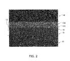
- FIG. 2 shows an example of a cross section.
- element mapping is performed in relation to the 20 cross sections.
- the element mapping is executed using FE-EPMA (a field-emission electron probe microanalyzer).
- the name of the apparatus that is employed is an field emission analytic electronic microscope (JXA-8500F) manufactured by JEOL Ltd.
- JXA-8500F field emission analytic electronic microscope
- the position at which the cerium concentration coincides with the zirconium concentration is specified as the position of the barrier-buffer interface 17 based on the resulting signal strength.
- a position on the line that shows a value that is 80% of the maximum value of the zirconium concentration in the electrolyte layer is specified as the position of the buffer-electrolyte layer 18.
- the respective concentration of Gd and Y atoms is calculated based on the signal intensity. Furthermore, the concentration of CeO 2 , Gd 2 O 3 , ZrO 2 and Y 2 O 3 is calculated from the atomic concentration.
- the concentration on each line that is to say, the concentration at a position that differs with respect to the thickness direction (concentration distribution) is calculated.
- FIG. 3 illustrates an example of the concentration distribution is the distribution of each substance obtained in the field of vision in FIG. 2 .
- the horizontal axis shows the distance from the proximity to the upper surface of the barrier layer 13, and the vertical axis illustrates the concentration of the substance at each position.
- the reliability of the contact interface was evaluated by testing of the cell represented by the stacked body configured from different materials through application of thermal cycle test.
- the testing sequence will be described below.
- a cell test material was prepared in the sequence that is the same as A above. However, the cathode was not formed.
- Thermal cycle test (100 times continuously) is performed in which the cell test material is heated under a condition of 700° C for 5 minutes in an infrared lamp-type electrical furnace in Air, and then cooled for 20 minutes by furnace cooling. After completion of testing, the presence or absence of film peeling in the cell test material is evaluated visually and by microscopic observation.
- the buffer layer 16 that is disposed between the anode 11, the barrier layer 13, the electrolyte layer 15, the barrier layer 13, and the electrolyte layer 15 is observed in cross section.
- a plurality of pores (indicated by the arrows in FIG. 2 ) is observed in the barrier layer 13.
- a pore with a relatively large diameter in the barrier layer 13 is present in a range within 1.2 ⁇ m in the direction of thickness from the barrier-buffer interface 17.
- a portion having a thickness of 1.2 ⁇ m is deemed to be a first barrier layer 131.
- the major-axis diameter of the pores contained in the first barrier layer 131 in the 20 fields of vision is between 0.05 ⁇ m - 1 ⁇ m, and the average value is 0.3 ⁇ m.
- the pore ratio of the first barrier layer 131 is 10%.
- the average value of the major-axis pore diameter in the second barrier layer 132 is 0.2 ⁇ m, and is smaller than the average value of the major-axis diameter in the first barrier layer 131. Furthermore, the pore ratio of the second barrier layer 132 is 7%, and is lower than that of the first barrier layer 131.
- the pore ratio of the electrolyte layer 15 and the buffer layer 16 is 0.2%.
- the second barrier layer 132 has a high density.
- the first barrier layer 131 suppresses peeling of the barrier layer 13 from the electrolyte layer 15, and the second barrier layer 132 imparts low electrical resistance and a superior barrier function.
- the thickness of the buffer layer 16 in the field of vision within FIG. 2 is approximately 1 ⁇ m.
- the scope of the composition of the buffer layer 16 is 3.2 mol% ⁇ Y 2 O 3 ⁇ 6mol%, 44 mol% ⁇ ZrO 2 ⁇ 74mol%, 4.0 mol% ⁇ Gd 2 O 3 ⁇ 10 mol%, and 16 mol% ⁇ CeO 2 ⁇ 44 mol%.
- the buffer layer 16 includes a concentration gradient for components included in the barrier layer 13, and a concentration gradient in particular of CeO 2 .
- the CeO 2 concentration shows a substantially monotonic decrease from the barrier-buffer interface 17 to the buffer-electrolyte interface 18.
- the CeO 2 concentration in the buffer layer 16 shows 16 mol% that is the minimum value in the buffer-electrolyte interface 18, and shows 44 mol% that is the maximum value in the barrier-buffer interface 17.
- the buffer layer 16 includes a concentration gradient for components included in the electrolyte layer 15, and a concentration gradient in particular of ZrO 2 .
- the ZrO 2 concentration shows a substantially monotonic increase from the barrier-buffer interface 17 to the buffer-electrolyte interface 18.
- the ZrO 2 concentration in the buffer layer 16 shows 74 mol% that is the maximum value in the buffer-electrolyte interface 18, and shows 44 mol% that is the minimum value in the barrier-buffer interface 17.
- the first barrier layer 131 also has a CeO 2 concentration gradient and a ZrO 2 concentration gradient.
- CeO 2 concentration shows a substantially monotonic increase in relation to the distance from the barrier-buffer interface 17
- the ZrO 2 concentration shows a substantially monotonic decrease in relation to the distance from the barrier-buffer interface 17 in the first barrier layer 131.
Landscapes
- Chemical & Material Sciences (AREA)
- Engineering & Computer Science (AREA)
- Chemical Kinetics & Catalysis (AREA)
- Electrochemistry (AREA)
- General Chemical & Material Sciences (AREA)
- Manufacturing & Machinery (AREA)
- Life Sciences & Earth Sciences (AREA)
- Sustainable Development (AREA)
- Sustainable Energy (AREA)
- Composite Materials (AREA)
- Materials Engineering (AREA)
- Physics & Mathematics (AREA)
- Thermal Sciences (AREA)
- Fuel Cell (AREA)
- Inert Electrodes (AREA)
Abstract
Description
- This application claims priority under 35 U.S.C. § 119 to Japanese Patent Application No.
2010-136372, filed on June 15, 2010 2011-96518, filed on April 22, 2011 2010-136372 2011-96518 - The present invention relates to a fuel cell, and in particular, relates to a solid-oxide fuel cell.
- In recent years, fuel cells have attracted attention in light of effective use of energy resources and environmental problems. A fuel cell stack includes a fuel cell and an interconnector.
Patent Literature 1 discloses a fuel cell stack that includes a solid electrolyte layer, and an anode and a cathode that are opposed through the solid electrolyte layer. - A fuel cell that includes at least two layers having a different composition is associated with the disadvantage that the coefficient of thermal expansion and/or the firing contraction amount in the respective layers differs in response to heat produced during manufacture and/or use. More specifically, this disadvantage includes the production of a crack in one of the layers and peeling of one layer from the other layer as a result of a distortion caused by thermal stress.
- The present invention is proposed in light of the above problems, and has the object of suppressing the production of such a disadvantage in a fuel cell.
- A fuel cell according to a first aspect of the present invention is provided that includes an anode, a cathode, a solid electrolyte layer, a barrier layer, and an buffer layer. The solid electrolyte layer includes zirconium and is provided between the anode and the cathode. The barrier layer includes cerium and is provided between the solid electrolyte layer and the cathode. The barrier layer has pores. The buffer layer includes zirconium and cerium and is provided between the barrier layer and the solid electrolyte layer. The barrier layer has a first barrier layer provided near to the buffer layer with a first pore ratio and a second barrier layer provided between the first barrier layer and the cathode with a second pore ratio. The first pore ratio of the first barrier layer is larger than the second pore ratio of the second barrier layer.
- Since the fuel cell according to the present invention has a barrier layer that includes pores, heat stress between the barrier layer and the solid electrolyte layer is reduced, and the attachment strength between the barrier layer and the solid electrolyte layer is increased by the buffer layer to thereby suppress peeling between the barrier layer and the solid electrolyte layer.
-
-
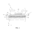
FIG. 1 is a cross sectional view illustrating the main components of a fuel cell stack. -
FIG. 2 is an SEM image illustrating a cross sectional view of a cell test material in the present embodiment. -
FIG. 3 is a graph illustrating the concentration distribution of each component illustrated inFIG. 2 . -
FIG. 4 is a cross sectional view of a fuel cell including a second barrier layer. -
FIG. 5 is a perspective view illustrating the outer appearance of a segmented-in-series fuel cell. -
FIG. 6 is a cross sectional view along the arrow I-I of the segmented-in-series fuel cell inFIG. 5 . - A solid oxide fuel cell (SOFC) is an example of a fuel cell. In particular, the following description mainly relates to a SOFC that includes a cell-stack structure in which a plurality of fuel cells is stacked.
- As illustrated in
FIG. 1 , afuel cell stack 10 includes a fuel cell (simply termed a "cell") 1 and acurrent collecting member 4. Although thefuel cell stack 10 is a vertically-striped fuel cell, the present invention can also be applied to configurations other than a segmented-in-series configuration as described below. A plurality ofcells 1 in thefuel cell stack 10 is stacked in the y-axis direction through thecurrent collecting member 4. That is to say, thefuel cell stack 10 includes a plurality of stackedcells 1. - The
cell 1 is a thin ceramic plate. The thickness of thecell 1 is for example 30 µm to 300 µm, and the diameter of thecell 1 is for example 5 mm to 50 mm. Thecell 1 as illustrated inFIG. 1 includes ananode 11, abarrier layer 13, acathode 14, anelectrolyte layer 15, and anbuffer layer 16. - The
electrolyte layer 15 is disposed between theanode 11 and thecathode 14. Thebarrier layer 13 is disposed between theelectrolyte layer 15 and thecathode 14. Thebuffer layer 16 is disposed between theelectrolyte layer 15 and thebarrier layer 13. Thebuffer layer 16 makes contact with theelectrolyte layer 15, and thebuffer layer 16 makes contact with thebarrier layer 13. The interface between thebarrier layer 13 and thebuffer layer 16 is termed a barrier-buffer interface layer 17, and the interface between theelectrolyte layer 15 and thebuffer layer 16 is termed an buffer-electrolyte interface layer 18. - The material used in the
anode 11 for example includes a material used in the anode in a known fuel cell. More specifically, the material used in theanode 11 may include NiO - YSZ (nickel oxide - yttria-stabilized zirconia) and/or NiO-Y2O3 (nickel oxide - yttria). Theanode 11 may include these materials as a main component. Furthermore, theanode 11 may function as a base plate (in other words, a support body) that supports the other layers included in thecell 1. That is to say, the thickness of theanode 11 may represent the maximum thickness in the plurality of layers contained in thecell 1. More specifically, the thickness of theanode 11 is of the order of 10 µm to 300 µm. Theanode 11 can be imparted conductive properties by application of a reduction treatment (for example, a treatment of reducing NiO to Ni). - The term "composition A includes material B as a main component" preferably means that the content of material B in composition A is at least 60 wt%, and still more preferably, means that the content of material B in composition A is at least 70wt%.
- The
anode 11 may include at least two layers. For example, theanode 11 may have two layers, that is to say, a base plate and an anode-active layer (fuel side electrode) formed thereon. The material in the base plate and the anode-active layer may be selected from the materials for theanode 11 as described above. More specifically, a combination may be used in which the base plate is formed from NiO-Y2O3 and the anode-active layer is formed from NiO -YSZ. - The
barrier layer 13 includes cerium. The barrier layer may include cerium in the form of ceria (cerium oxide). More specifically, materials that are used in thebarrier layer 13 include ceria and ceria-based materials including rare-earth metal oxides configured as a solid solution into ceria. Thebarrier layer 13 may include a ceria-based material as a main component. More specifically, the ceria-based material includes GDC ((Ce, Gd)O2: gadolinium doped ceria), SDC ((Ce, Sm)O2: samarium doped ceria). For example, the mol composition ratio of the rare earth metal oxide to ceria may be 5 to 95 - 20 to 80. Thebarrier layer 13 may include additives in addition to a ceria-based material. - The thickness of the
barrier layer 13 for example may be 40 µm or less, may be 30 µm or less, or may be 20 µm or less. - The
barrier layer 13 suppresses formation of a high resistance layer by suppressing the diffusion of cations from thecathode 14 into theelectrolyte layer 15. As a result, thebarrier layer 13 enables suppression of a reduction in the output density, and increases the product life of thecell 1. - The
barrier layer 13 includes afirst barrier layer 131 and asecond barrier layer 132. - The
first barrier layer 131 includes pores, and is present in a range within 2.0 pm from the barrier-buffer interface 17. In the present embodiment, as illustrated inFIG. 1 , the region from the barrier-buffer interface 17 to theintermediate surface 13a corresponds to thefirst barrier layer 131, and the distance from the barrier-buffer interface 17 to theintermediate surface 13a is no more than 2.0 µm. That is to say, in the present embodiment, the thickness of thefirst barrier layer 131 is no more than 2.0 µm. - The
first barrier layer 131 includes a plurality ofpores 13c. There is no limitation on the shape of thepores 13c, and the cross sectional shape of thepores 13c may be substantially oval (including circular). The major-axis diameter R of thepore 13c preferably satisfies the relationship R ≤ 1 µm, and the major-axis diameter R preferably satisfies the relationship 0.05 µm ≤ R. - At least a portion of the
pores 13c may be closed pores. Furthermore all of thepores 13c contained in thefirst barrier layer 131 may be closed pores. The closed pores may be disposed in thecell 1, that is to say, in thefirst barrier layer 131, and the inner portion of the closed pores may be isolated from the outer air of thecell 1. The inclusion of closed pores in thefirst barrier layer 131 enables thefirst barrier layer 131 to exhibit an effect that substantially mitigates the distortion, that is to say, an effect that substantially mitigates thermal stress. Furthermore, even when a crack is generated in thebarrier layer 13, the inclusion of closed pores suppresses increase in crack width. Thesecond barrier layer 132 may include pores, and at least a portion of the pores may be closed pores. - The pore ratio P1 of the
first barrier layer 131 preferably satisfies the relationship P1 ≤ 15%, and the pore ratio P1 preferably satisfies therelationship 1% ≤ P1. The pore ratio may be expressed as a space ratio. Although the pore ratio P1 is expressed by the ratio of the volume V2 of the space (including thepores 13c) with respect to the total volume V1 of the first barrier layer 131 (V2/V1), it may be expressed as the surface area of thepores 13c per unit area in cross section of the first barrier layer. - The pore ratio P for example is acquired by
- acquiring a scanning electron microscope (SEM) image in cross section with respect to the thickness dimension of the
first barrier layer 131, - specifying the
pores 13c in the image (field of vision), - acquiring the surface area of the
first barrier layer 131 in the image, - acquiring the sum of the surface area of the
pores 13c in the image, and - calculating "the sum of the surface area of the
pores 13c divided by surface area of thefirst barrier layer 131" in the image. - With respect to the
first barrier layer 131, the number of pores per 10 µm length with respect to a direction that is parallel to the interface direction between layers in a cross section that is parallel to the thickness direction of thefirst barrier layer 131 is preferably 5 or less. - Since the composition of the
barrier layer 13 is different from the composition of theelectrolyte layer 15, the coefficient of thermal expansion and firing contraction amount of thebarrier layer 13 is different from the coefficient of thermal expansion and firing contraction amount of theelectrolyte layer 15. Since thebarrier layer 13 and theelectrolyte layer 15 are fired in a stacked configuration during manufacture of thecell 1, a distortion is formed in an inner portion of thebarrier layer 13 and theelectrolyte layer 15. Thecell 1 is then subjected to a high temperature during operation, and returns to an ambient temperature during a non-operational period. When thebarrier layer 13 and theelectrolyte layer 15 repetitively shift between an ambient temperature state and a high temperature state when a distortion is present, peeling may result on the interface between thebarrier layer 13 and theelectrolyte layer 15 as a result of the distortion. The abarrier 13 that includes afirst barrier layer 131 that haspores 13c mitigates the stress, and suppresses peeling. - The
first barrier layer 131 may contain zirconium. The average content amount of zirconium in the first barrier layer 131 (that is to say, the concentration of zirconium) is preferably lower than the average content amount of cerium (that is to say, the concentration of cerium). More specifically, "concentration" as used herein is a value that is obtained by line analysis based on an atomic concentration profile as described hereafter. - The
second barrier layer 132 is disposed between thefirst barrier layer 131 and thecathode 14. More specifically, thesecond barrier layer 132 occupies the area from theintermediate surface 13a that is the upper surface of thefirst barrier layer 131 to the upper surface of the barrier layer 13 (inFIG. 1 , theinterface 13b between thebarrier layer 13 and the cathode 14). - The pore ratio P2 of the
second barrier layer 132 is preferably lower than the pore ratio P1 of thefirst barrier layer 131. More specifically, the pore ratio P2 of thesecond barrier layer 132 preferably satisfies the relationship P2 ≤ 10%. - The ratio of the pore ratio P2 of the
second barrier layer 132 to the pore ratio P1 of the first barrier layer 131 (P2/P1) preferably satisfies the relationship P2/P1 ≤ 0.7. - The average value of the major-axis diameter of the pores contained in the
second barrier layer 132 is preferably smaller than the average value of the major-axis diameter of thepores 13c contained in thefirst barrier layer 131. - The effect of suppressing cation diffusion by the
second barrier layer 132 is enhanced by configuring the pore ratio of thesecond barrier layer 132 to take a small value, and/or making the pores in thesecond barrier layer 132 small. Furthermore the electrical resistance value of thecell 1 is suppressed to a low value by providing thesecond barrier layer 132 in a dense configuration. The pore ratio of thesecond barrier layer 132 is calculated in the same manner as the pore ratio of thefirst barrier layer 131. - A cathode material for a known fuel cell is used as the material of the
cathode 14. More specifically, the material in thecathode 14 includes LSCF (lanthanum strontium cobalt ferrite: (LaSr)(CoFe)O3). The composition of LSCF for example includes La0.6Sr0.4Co0.2Fe0.8O3. Thecathode 14 may include the above materials as a main component. The thickness of thecathode 14 may be of the order of 5 µm - 50 µm. - The
electrolyte layer 15 is an example of a solid electrolyte layer, and contains zirconium. Theelectrolyte layer 15 may include zirconium in the form of zirconia (ZrO2). More specifically, theelectrolyte layer 15 may include zirconia as a main component. Theelectrolyte layer 15 may include an additive such as Y2O3 and/or Sc2O3 in addition to zirconia. These additives may function as a stabilizer. In theelectrolyte layer 15, the stabilizer may have a mol composition ratio with respect to zirconia of 3:97 - 20:80. In other words, the material used in theelectrolyte layer 15 includes zirconia-based materials such as yttria-stabilized zirconia including 3YSZ, 8YSZ, and 10YSZ, and ScSZ (scandia-stablized zirconia) or the like. - The thickness of the
electrolyte layer 15 may be 30 µm or less. - The pore ratio of the
electrolyte layer 15 is preferably less than the pore ratio of thefirst barrier layer 131, and preferably less than the pore ratio of thesecond barrier layer 132. More specifically, the pore ratio of theelectrolyte layer 15 may be no more than 7%, or no more than 5%, or no more than 3%. The pore ratio of theelectrolyte layer 15 is calculated in the same manner as the pore ratio of thefirst barrier layer 131 as described above. - The
buffer layer 16 includes zirconium and cerium. The zirconium and cerium may be in the form of ceria and zirconia, and may be included in thebuffer layer 16. The zirconium (or zirconia) and cerium (or ceria) in thebuffer layer 16 may be mixed, and thebuffer layer 16 is preferably a solid solution of ceria and zirconia. Thebuffer layer 16 may include a material other than cerium and zirconium. Thebuffer layer 16 may include for example a material (additive or the like) that is included in thebarrier layer 13 or theelectrolyte layer 15. When theelectrolyte layer 15 contains yttrium (Y), thebuffer layer 16 also contains yttrium. When thebarrier layer 13 includes gadolinium (Gd), thebuffer layer 16 also contains gadolinium.
Thebuffer layer 16 increases the attachment strength between thebarrier layer 13 and theelectrolyte layer 15 and suppresses peeling.
Thebarrier layer 13, theelectrolyte layer 15, and thebuffer layer 16 may be co-fired. - In the
buffer layer 16, the cerium concentration D1 and the zirconium concentration D2 (D2/D1) may satisfy (1) to (8) below. - (1) The ratio of the cerium concentration D1 to the zirconium concentration D2 (D2/D1) is preferably 0.1 ≤ D1/D2.
- (2) D1/D2 preferably satisfies D1/D2 ≤ 1.
- (3) The concentration D1 of cerium preferably satisfies D1 ≤ 40 mol%.
- (4) The concentration D1 preferably satisfies 10 mol% ≤ D1.
- (5) The concentration D2 of zirconium preferably satisfies D2 ≤ 80 mol%.
- (6) The concentration D2 preferably satisfies 50 mol% ≤ D2.
- (7) The ratio (D1/D3) of the concentration D1 of cerium in the
buffer layer 16 relative to the concentration D3 of cerium in thebarrier layer 13 may satisfy D1/D3 ≤ 0.5. - (8) The ratio (D2/D4) of the concentration D2 of zirconium in the
buffer layer 16 relative to the concentration D4 of zirconium in theelectrolyte layer 15 may satisfy D2/D4 ≤ 0.9. - Any one of the conditions in conditions (1) to (8) may be satisfied, or two or more conditions may be satisfied.
Furthermore, in the absence of a specific limitation on the "concentration" of the components in each layer discussed in this document and the concentrations D1 to D4, it is the concentration in the each overall layer, that is to say, the average content amount of a component (for example, zirconium or cerium and so on) in each layer. - More specifically, "concentration" is obtained by line analysis using a atomic concentration profile, that is to say, it is obtained by a comparison between the characteristic X-ray intensity using an EPMA (electron probe micro analyzer).
- Quantitative analysis using EPMA is known to a person skilled in the art. EPMA is an apparatus that detects and identifies the component elements in a minute region (approximately 1 µm3) onto which an electron beam is illuminated based on the characteristic X-ray spectrum that is irradiated by illumination of an electron beam onto a target object, and then analyzes the ratio (concentration) of each component element. Quantitative analysis using EPMA is executed by comparison of the characteristic X-ray intensity of a reference test material that has a clear element concentration and a characteristic X-ray intensity of an unknown test material.
- In other words, concentration distribution data for each element is acquired by line analysis with respect to a thickness dimension (y direction) using EPMA in a cross section that is substantially parallel to the thickness dimension (y axial direction) in the
cell 1. - That is to say, the concentration D1 - D4 can be determined by element mapping using an EPMA (electron problem micro analyzer).
In the present specification, EPMA is a concept that includes EDS (energy dispersive x-ray spectroscopy). - The position of the barrier-
buffer interface 17 can be specified as described hereafter with reference to a cross section of acell 1 that is substantially parallel to the thickness dimension (y axial direction). In other words, when the position of the barrier-buffer interface 17 is determined, the concentration distribution data for each element can be acquired by executing a line analysis in the layer thickness dimension (y direction) using EPMA in a cross section that is substantially parallel thickness dimension (y direction). This concentration distribution data can be used to determine the position of the line that corresponds with the concentration of cerium and the concentration of zirconium as the position of the barrier-buffer interface 17.
That is to say, the concentration of zirconium and the concentration of cerium is substantially the same in proximity to the barrier-buffer interface 17. - The position of the buffer-
electrolyte interface 18 is specified as the line position that demonstrates 80% concentration of the maximum concentration of zirconium in the cross section (the maximum zirconium concentration in the electrolyte layer). - The distribution of the cerium concentration and the zirconium concentration in the
buffer layer 16 may satisfy the conditions (a) to (e) below. - (a) The
buffer layer 16 preferably includes a cerium concentration gradient. The horizontal axis of the graph showing the cerium concentration gradient includes that shows the distance from the barrier-buffer interface 17 to the portion at an arbitrary position in thebuffer layer 16, the maximum distance value is the distance from the barrier-buffer interface 17 to the buffer-electrolyte interface 18. The vertical axis shows the cerium concentration in that portion. The graph preferably shows a monotonic decrease in the cerium concentration in response to an increase in the distance.
That is to say, when the concentration gradient is present, and if thebuffer layer 16 is divided into a plurality of portions in a cross section that is parallel to the buffer-electrolyte interface 18, the portion that is in proximity to the barrier-buffer interface 17 in thebuffer layer 16 shows a tendency to have a higher cerium concentration than a portion in proximity to the buffer-electrolyte interface 18 in thebuffer layer 16. - (b) The cerium concentration in a portion that is positioned in proximity to the barrier-
buffer interface 17 in a portion of thebuffer layer 16 preferably is close to the cerium concentration of thebarrier layer 13. More specifically, the cerium concentration of the portion that is positioned in proximity to the barrier-buffer interface 17 and is a portion of thebuffer layer 16 is preferably substantially the same as the cerium concentration in a portion that is positioned in proximity to the barrier-buffer interface 17 and is a portion of thebarrier layer 13. - (c) The
buffer layer 16 is preferably includes a zirconium concentration gradient. The horizontal axis of the graph illustrating the zirconium concentration gradient shows the distance from the barrier-buffer interface 17 in the same manner as the graph in (a) above. When the vertical axis shows the zirconium concentration, the zirconium concentration in this graph preferably increases in a monotonic manner substantially in response to the increase in the distance. - (d) The zirconium concentration of the position in proximity to the buffer-
electrolyte interface 18 and is a portion of thebuffer layer 16 is preferably close to the zirconium concentration of theelectrolyte layer 15. More specifically, the zirconium concentration of the portion that is positioned in proximity to the buffer-electrolyte interface 18 and is a portion of thebuffer layer 16 is preferably substantially the same as the zirconium concentration in a portion that is positioned in proximity to the buffer-electrolyte interface 18 and is a portion of theelectrolyte layer 15. - Any one of the conditions in conditions (a) to (d) may be satisfied, or two or more conditions may be satisfied. The greater a number of conditions is satisfied, the more it is preferred.
- For example, when (a) to (d) are satisfied, the
cell 1 has a concentration gradient that shows a gradually decreasing cerium concentration and a gradually increasing zirconium concentration from the lower surface of thebarrier layer 13 to the upper surface of theelectrolyte layer 15. - In the region from the
barrier layer 13 to theelectrolyte layer 15, the result is obtained that peeling between thebarrier layer 13 and theelectrolyte layer 15 is prevented by the gradual variation in the composition in response to the distance from the barrier layer 13 (this may also be expressed as the distance from the electrolyte layer 15). - The cerium concentration and the zirconium concentration in (a) to (d) above may be a value that is obtained by line analysis using EPMA.
- The thickness of the
buffer layer 16, that is to say, the distance from the buffer-electrolyte interface 18 to the barrier-buffer interface 17 is preferably at least 0.5 µm and preferably no more than 2 µm. - The ratio of the pore ratio P3 in the
buffer layer 16 relative to the pore ratio P1 in the first barrier layer 131 (P3/P1) is preferably no more than 0.3. - The coefficient of thermal expansion of the buffer layer 16 (that is to say, the coefficient of linear expansion) is a value between the coefficient of thermal expansion of the
electrolyte layer 15 and the coefficient of thermal expansion of thebarrier layer 13. In other words, when the coefficient of thermal expansion of thebarrier layer 13 is higher than the coefficient of thermal expansion of theelectrolyte layer 15, the coefficient of thermal expansion of thebuffer layer 16 is higher than theelectrolyte layer 15, and lower than the coefficient of thermal expansion of thebarrier layer 13. For example, the coefficient of thermal expansion of thebuffer layer 16 may be greater than the coefficient of thermal expansion of YSZ that is an example of theelectrolyte layer 15, and smaller than the coefficient of thermal expansion of GDC that is an example of thebarrier layer 13. - The fuel cell may include an anode, an electrolyte layer and a cathode. That is to say, the
cell 1 as described above is merely an example of a fuel cell. Thus in thecell 1, further additions of component elements, or variation to the shape, material and dimensions or the like of the component elements in thecell 1 are possible. For example, in thecell 1, a layer in addition to the layers described above may be further provided between theanode 11 and theelectrolyte layer 15 and/or thecathode 14 and thebarrier layer 13. - For example, a second barrier layer may be further provided between the
barrier layer 13 and thecathode layer 14. -
FIG. 4 shows the fuel cell (hereinafter simply referred to as a "cell") 20 that includes a second barrier layer. InFIG. 4 , those component elements that are the same as the component elements in the cell illustrated inFIG. 1 are denoted by the same reference numbers and the corresponding description will not be repeated.
As illustrated inFIG. 4 , thecell 20 includes thebarrier layer 13 as a first barrier layer, and asecond barrier layer 21 that is provided between thebarrier layer 13 and thecathode 14. The material that configures thesecond barrier layer 21 may be the same material as thebarrier layer 13. Furthermore the density of thesecond barrier layer 21 may be lower than the density of thefirst barrier layer 13. In other words, thesecond barrier layer 21 includes pores, and the pore ratio of thesecond barrier layer 21 may be greater than the pore ratio of thefirst barrier layer 13. - The configuration of the fuel cell may be varied in the following manner.
- (1) The shape of the cell may includes an anode-supporting configuration, a flat-plate configuration, a cylindrical configuration, a vertically-striped configuration, a segmented-in-series configuration, a single-end support stack configuration or a double-end support stack configuration. The cross sectional surface of the cell may be oval.
- (2) In another configuration, the anode in the
cell - (3) A configuration in another aspect is possible by combination of the above.
- A current collecting pore (not shown) and a
conductive connection portion 41 are provided in the current collectingmember 4. A plurality ofconductive connection portions 41 is provided in the current collectingmember 4. - As illustrated in
FIG. 1 , theconductive connection portions 41 are configured as an indented portion provided in the current collectingmember 4, and the bottom portion thereof is connected through aconductive adhesive 411 to thecathode 14. As illustrated inFIG. 1 , a non-connected position is provided between theconductive connection portions 41 and its periphery in the current collectingmember 4. In that manner, as described hereafter, air is supplied to thecathode 14. - During power generation, fuel gas is supplied to the
anode 11. The supply of air to thecathode 14 draws air from the side surface of the cell stack structure (the front of the face of the page inFIG. 1 ). - Although this is not shown, the
fuel cell stack 10 further includes a member such as a lead that sends a current generated by the cell stack to an external apparatus and a gas reforming unit that includes an enzyme or the like for reforming the fuel gas. - The
fuel cell stack 10 described above includes a plurality ofstacked cells 1 and acurrent collecting member 4 connecting thecells 1 electrically In other words, thefuel cell stack 10 is a vertically-striped fuel cell. However, the present invention may also be applied to a segmented-in-series fuel cell. A segmented-in-series fuel cell will be described below. - The segmented-in-series fuel cell (hereinafter simply referred to as a "fuel cell stack") 100 includes a
support base plate 102, ananode 103, anelectrolyte layer 104, acathode 106, aninterconnector 107, acurrent collector 108, abarrier layer 13 and anbuffer layer 16. Thefuel cell stack 100 includes acell 110. Those component elements that are the same as the component elements already described above are denoted by the same reference numerals, and such description will not be repeated. InFIG. 5 , for sake of convenience of description, thecurrent collector 108 is not illustrated. - The
fuel cell stack 100 includes a plurality ofcells 110 disposed on thesupport base plate 102 and aninterconnector 107 that is electrically connected between thecells 110. Thecells 110 include ananode 103 and acathode 106 that corresponds to theanode 103. More specifically, thecells 110 include ananode 103, anelectrolyte layer 104 and acathode 106 stacked with reference to the thickness direction (y axis direction) of thesupport base plate 102. - The
support base plate 102 is flat and elongated in one direction (z axis direction). Thesupport base plate 102 is a porous body that has insulating properties. Thesupport base plate 102 may include nickel. More specically, thesupport base plate 102 may contain Ni-Y2O3 (nickel yttria) as a main component. The nickel may be included as an oxide (NiO). During power generation, NiO may be reduced to N by oxygen gas. - As illustrated in
FIG. 5 andFIG. 6 , aflow path 123 is provided in an inner portion of thesupport base plate 102. Theflow path 123 extends along the longitudinal direction (z axis direction) of thesupport base plate 102. During power generation, fuel gas flows into theflow path 123, through the hole that is provided in thesupport base plate 102 to thereby supply fuel gas to theanode 103 described below. - The
anode 103 is provided on thesupport base plate 102. A plurality ofanodes 103 is disposed on a singlesupport base plate 102 and arranged in the longitudinal direction (z axial direction) of thesupport base plate 102. That is to say, a space is provided betweenadjacent anodes 103 in the longitudinal direction (z axis direction) of thesupport base plate 102. - The composition of the
anode 103 may be the same as the composition of theanode 11. Theanode 103 may include an anode current collecting layer and an anode active layer. The anode current collecting layer is provided on thesupport base plate 102, and the anode active layer is provided to avoid superimposition with respect to theinterconnector 107 on the anode current collecting layer. - The
anode 103 may include an anode current collecting layer and an anode active layer. The anode current collecting layer is provided on thesupport base plate 102 and the anode active layer is provided on the anode current collecting layer. The composition of the anode current collecting layer and the anode active layer has been described above. - The
electrolyte layer 104 is also termed a solid electrolyte layer. As illustrated inFIG. 6 , theelectrolyte layer 104 is provided on theanode 103. In a region that is not provided with theanode 103 on thesupport base plate 102, theelectrolyte layer 104 may be provided on thesupport base plate 102. - The
electrolyte layer 104 includes a non-connected position in the longitudinal direction (z axis direction) of thesupport base plate 102. In other words, a plurality of electrolyte layers 104 is disposed at an interval in the z axis direction. Namely, the plurality of electrolyte layers 104 are provided along the longitudinal direction (z axis direction) of thesupport base plate 102.
Electrolyte layers 104 adjacent in the z axis direction are connected by aninterconnector 107. In other words, the electrolyte layers 104 are connected from aninterconnector 107 to aninterconnector 107 that is adjacent to theinterconnector 107 in the longitudinal direction (z axis direction) of thesupport base plate 102. Theinterconnector 107 and theelectrolyte layer 104 have a dense structure in comparison to thesupport base plate 102 and theanode 103. Therefore, theinterconnector 107 and theelectrolyte layer 104 function as a seal portion that partitions air and fuel gas by the provision of a connected structure in the z axis direction in thefuel cell stack 100. - The composition of the
electrolyte layer 104 includes a composition that is the same as theelectrolyte layer 15 as described above. - The same description provided in relation to the vertically-striped fuel cell applies to the configuration of the
barrier layer 13 and thebuffer layer 16. - The
buffer layer 16 is provided on theelectrolyte layer 104. InFIG. 6 , thebuffer layer 16 is not provided at a position without theelectrolyte layer 104. That is to say, onebuffer layer 16 is provided corresponding to oneanode 103.
Thebarrier layer 13 is provided between thebuffer layer 16 and thecathode 106. - The
cathode 106 is disposed on thebarrier layer 13 without projecting from the outer edge of thebarrier layer 13. Onecathode 106 is stacked on oneanode 103. That is to say, a plurality ofcathodes 106 is provided along the longitudinal direction (z axis direction) of thesupport base plate 102 on a singlesupport base plate 102. - The composition of the
cathode 106 includes the composition of thecathode 14 as described above. - As described above, the
interconnector 107 may be disposed to configure electrical contact between thecells 110. InFIG. 6 , theinterconnector 107 is stacked onto theanode 103. Theinterconnector 107 may be directly connected onto theanode 103. - In the present specification, "stack" includes the disposition of two elements in connection and a disposition that provides an overlap in the y axis direction although there is not a connection.
- In
FIG. 6 , as described above, theinterconnector 107 is disposed to connect the electrolyte layers 104 in the longitudinal direction (z axis direction) of thesupport base plate 102. In this manner,cells 110 that are adjacent in the longitudinal direction (z axis direction) of thesupport base plate 102 are electrically connected. - The
interconnector 107 is a dense layer in comparison to thesupport base plate 102 and theanode 103. Theinterconnector 107 contains a perovskite composite oxide as a main component. In particular, a chromite-based material is an example of a perovskite composite oxide. - The
current collector 108 is disposed to electrically connect theinterconnector 107 and thecell 110. More specifically, thecurrent collector 108 provides a connection from thecathode 106 to theinterconnector 107 in acell 110 that is adjacent to acell 110 with thecathode 106. Thecurrent collector 108 may have conductive properties, and for example, may be configured from the same material as theinterconnector 107. - A layer that contains at least one type of element of the elements that configure the
anode 103 and at least one element of the elements that configure theinterconnector 107 may be disposed between theanode 103 and theinterconnector 107. - The
cathode 106 contained in thecell 110 is electrically connector with theanode 103 of theadjacent cell 110 by thecurrent collector 108 and theinterconnector 107. That is to say, in addition to theinterconnector 107, thecurrent collector 108 also may participate in the connection between thecells 110. This configuration is also included in the configuration of "the interconnector is electrically connected between the cells". - More specifically, the dimensions of each portion of the
fuel cell stack 100 may be set as described hereafter.
Width W1 of Support Base Plate 102: 1 - 10 cm
Thickness W2 of Support Base Plate 102: 1 - 10 mm
Length W3 of Support Base Plate 102: 5 - 50 cm
Distance W4 from outer surface of Support Base Plate 102 (interface between thesupport base plate 102 and the anode) to Flow path 123: 0.1 - 4 mm
Thickness of Anode 103: 50 - 500 µm
(When theanode 103 includes an anode current collecting layer and an anode active layer: - Thickness of anode current collecting layer: 50 - 500 µm
- Thickness of anode active layer: 5 - 30 µm)
- Thickness of electrolyte layer 104: 3 - 50 µm
- Thickness of cathode 106: 10 - 100 µm
- Thickness of interconnector 107: 10 - 100 µm
- Thickness of current collector 108: 50 - 500 µm
- The method of manufacture as described below is merely exemplary of the method of manufacture of the
cell 1. In other words, the various conditions in relation to the devices used, the time, temperature, pressure, and materials as described above may be varied. - The
anode 11 may be formed by stacking a plurality of ceramic green sheets and applying thermo-compression bonding. The ceramic green sheet that configures theanode 11 for example may be formed from nickel oxide (NiO), zirconium-based materials (for example, 8YSZ), and a pore forming agent (for example, PMMA poly(methyl methacrylate resin). - The method of manufacturing the
cell 1 includes a step of forming thebuffer layer 16. In other words, the method of manufacturing thecell 1 includes a step of forming a layer that includes cerium and zirconium and pores. This step may be realized by a step of stacking the layer that includes a zirconium-based material as a main component (zirconia-based material layer) and a layer that includes a ceria-based material as a main component (ceria-based material layer), and a step of co-firing the stacked layers. A solid solution of ceria and zirconia is formed in the contact surface between the ceria-based material layer and the zirconia-based material layer as a result of the co-firing. - The method of forming the
buffer layer 16 is not limited to the above method, and for example, formation is also possible by stacking a material that has an adjusted concentration of cerium and zirconium. - The step of forming the
barrier layer 13 includes a step of forming a ceria-based material layer. The step of forming thebarrier layer 13 may include a step of stacking a ceria-based material layer with another layer having a different composition, and co-firing. The other layer includes for example a zirconia-based material layer. Pores can be formed in the ceria-based material layer by stacking layers having a different composition in the above manner and co-firing.
The step of forming theelectrolyte layer 15 includes a step of forming a zirconia-based material layer. The respective layers may include an additive in addition to a ceria-based material layer and a zirconia-based material layer. - The step of forming the ceria-based material layer may include the stacking of a ceramic green sheet that includes a ceria-based material with another layer (for example, a zirconia-based material layer, or a material layer forming the buffer layer). The step of forming the zirconia-based material layer may include the stacking of a ceramic green sheet that includes a zirconia-based material with another layer (for example, the anode 11). The stacked material layer is contact bonded with the other layer using a method such as CIP (cold isostatic press) or thermo-compression bonding.
- In addition to stacking of a ceramic green sheet, the ceria-based material layer and the zirconia-based material layer may form one or both of the
barrier layer 13 and theelectrolyte layer 15 using another method such as a slurry dip method, a brush coating method, a stamping method and/or a printing method. - The precise flow of the manufacturing method will now be described.
A stacked body can be obtained by stacking in order a zirconia-based material layer and a ceria-based material layer on a material layer forming theanode 11. A fired member can be obtained by degreasing and firing the laminated body. The firing forms the zirconia-based material layer into theelectrolyte layer 15, and forms the ceria-based material layer into thebarrier layer 13. Anbuffer layer 16 is formed between the zirconia-based material layer and the ceria-based material layer. The co-firing of the zirconia-based material layer and the ceria-based material layer enables formation of abarrier layer 13 including pores. - Next, a
cathode 14 is formed on the fired body. Thecathode 14 is formed by firing after imparting the fired body with a cathode material using a printing method or the like. The above series of steps completes thecell 1. - A ceramic green sheet (
thickness 100 µm) formed from nickel oxide (NiO), a zirconia-based material (8YSZ), and a pore forming agent (PMMA) are stacked to 300 µm, and then integrated by thermo-compression bonding (60° C, 3MPa). - The resulting stacked body includes a separately manufactured ceramic green sheet that is formed from 3YSZ and a ceramic green sheet that is formed from GDC that are stacked in order and subjected to thermo-compression bonding. In this manner, a stacked body is obtained by sequential stacking of the anode, the zirconia-based material layer and the ceria-based material layer.
The resulting stacked body is co-fired at 1150 - 1450° C for 1 - 20 hours. - Thereafter an LSCF film (30 µm) is applied to the ceria-based material layer (barrier layer) as a cathode, and fired for two hours at 1000 - 1150° C.
A cell test material is prepared by the above operations. - The test material obtained in the above step A is cut vertically with respect to the direction of layer thickness. An image of the resulting cross section is observed using SEM-EDS (scanning electron microscopy-energy dispersive x-ray spectroscopy).
- More specifically, an image is obtained in 20 different fields of view in relation to positions on a single cross section using a scanning electron microscope. Use of imaging software enables specification of pores in the resulting image (in the field of vision of the microscope) and enables determination of both position and size.
FIG. 2 shows an example of a cross section. - Furthermore, element mapping is performed in relation to the 20 cross sections. The element mapping is executed using FE-EPMA (a field-emission electron probe microanalyzer). The name of the apparatus that is employed is an field emission analytic electronic microscope (JXA-8500F) manufactured by JEOL Ltd. The position at which the cerium concentration coincides with the zirconium concentration is specified as the position of the barrier-
buffer interface 17 based on the resulting signal strength. Furthermore, a position on the line that shows a value that is 80% of the maximum value of the zirconium concentration in the electrolyte layer is specified as the position of the buffer-electrolyte layer 18. - The respective concentration of Gd and Y atoms is calculated based on the signal intensity.
Furthermore, the concentration of CeO2, Gd2O3, ZrO2 and Y2O3 is calculated from the atomic concentration. The concentration on each line, that is to say, the concentration at a position that differs with respect to the thickness direction (concentration distribution) is calculated.FIG. 3 illustrates an example of the concentration distribution is the distribution of each substance obtained in the field of vision inFIG. 2 . InFIG. 3 , the horizontal axis shows the distance from the proximity to the upper surface of thebarrier layer 13, and the vertical axis illustrates the concentration of the substance at each position. - The reliability of the contact interface was evaluated by testing of the cell represented by the stacked body configured from different materials through application of thermal cycle test. The testing sequence will be described below.
A cell test material was prepared in the sequence that is the same as A above. However, the cathode was not formed. Thermal cycle test (100 times continuously) is performed in which the cell test material is heated under a condition of 700° C for 5 minutes in an infrared lamp-type electrical furnace in Air, and then cooled for 20 minutes by furnace cooling.
After completion of testing, the presence or absence of film peeling in the cell test material is evaluated visually and by microscopic observation. - As illustrated in
FIG. 2 , thebuffer layer 16 that is disposed between theanode 11, thebarrier layer 13, theelectrolyte layer 15, thebarrier layer 13, and theelectrolyte layer 15 is observed in cross section. - A plurality of pores (indicated by the arrows in
FIG. 2 ) is observed in thebarrier layer 13. A pore with a relatively large diameter in thebarrier layer 13 is present in a range within 1.2 µm in the direction of thickness from the barrier-buffer interface 17. A portion having a thickness of 1.2 µm is deemed to be afirst barrier layer 131. - The major-axis diameter of the pores contained in the
first barrier layer 131 in the 20 fields of vision is between 0.05 µm - 1 µm, and the average value is 0.3 µm. When the number of pores included in thefirst barrier layer 131 in the 20 fields of vision is measured, an average number of four pores per 10 µm length was identified in a direction that is parallel to the barrier-buffer interface 17. The pore ratio of thefirst barrier layer 131 is 10%. - The average value of the major-axis pore diameter in the
second barrier layer 132 is 0.2 µm, and is smaller than the average value of the major-axis diameter in thefirst barrier layer 131. Furthermore, the pore ratio of thesecond barrier layer 132 is 7%, and is lower than that of thefirst barrier layer 131. - Almost no pores are observed in the
electrolyte layer 15 and thebuffer layer 16. The pore ratio of theelectrolyte layer 15 and thebuffer layer 16 is 0.2%. - That is to say, although pores are evident in the
first barrier layer 131, thesecond barrier layer 132 has a high density. Thefirst barrier layer 131 suppresses peeling of thebarrier layer 13 from theelectrolyte layer 15, and thesecond barrier layer 132 imparts low electrical resistance and a superior barrier function. - As illustrated in
FIG. 3 , the thickness of thebuffer layer 16 in the field of vision withinFIG. 2 is approximately 1 µm. The scope of the composition of thebuffer layer 16 is 3.2 mol% < Y2O3 ≤ 6mol%, 44 mol% < ZrO2 ≤ 74mol%, 4.0 mol% < Gd2O3 ≤ 10 mol%, and 16 mol% < CeO2 ≤ 44 mol%. - As illustrated in
FIG. 3 , thebuffer layer 16 includes a concentration gradient for components included in thebarrier layer 13, and a concentration gradient in particular of CeO2. In thebuffer layer 16, the CeO2 concentration shows a substantially monotonic decrease from the barrier-buffer interface 17 to the buffer-electrolyte interface 18. InFIG. 3 , the CeO2 concentration in thebuffer layer 16 shows 16 mol% that is the minimum value in the buffer-electrolyte interface 18, and shows 44 mol% that is the maximum value in the barrier-buffer interface 17. - The
buffer layer 16 includes a concentration gradient for components included in theelectrolyte layer 15, and a concentration gradient in particular of ZrO2. In thebuffer layer 16, the ZrO2 concentration shows a substantially monotonic increase from the barrier-buffer interface 17 to the buffer-electrolyte interface 18. For example, inFIG. 3 , the ZrO2 concentration in thebuffer layer 16 shows 74 mol% that is the maximum value in the buffer-electrolyte interface 18, and shows 44 mol% that is the minimum value in the barrier-buffer interface 17. - As clearly illustrated in
FIG. 3 , thefirst barrier layer 131 also has a CeO2 concentration gradient and a ZrO2 concentration gradient. In other words, CeO2 concentration shows a substantially monotonic increase in relation to the distance from the barrier-buffer interface 17, and the ZrO2 concentration shows a substantially monotonic decrease in relation to the distance from the barrier-buffer interface 17 in thefirst barrier layer 131. - As a result of the thermal cycle test, the peeling of the
barrier layer 13 from theelectrolyte layer 15 is not observed in the cell testing material obtained. In other words, a high quality cell is obtained that is adapted for use in a fuel cell. - Although the results described above are related to only one of the cell testing material obtained under the above manufacturing conditions, the same results are obtained in relation to other cell testing materials.
-
- 1
- FUEL CELL
- 10
- FUEL CELL STACK
- 11
- ANODE
- 13
- BARRIER LAYER
- 13a
- INTERMEDIATE SURFACE
- 13b
- INTERFACE
- 13c
- PORE
- 131
- FIRST BARRIER LAYER
- 132
- SECOND BARRIER LAYER
- 14
- CATHODE
- 15
- ELECTROLYTE LAYER
- 16
- BUFFER LAYER
- 17
- BARRIER-BUFFER INTERFACE
- 18
- BUFFER-ELECTROLYTE INTERFACE
- 4
- CURRENT COLLECTING MEMBER
- 41
- CONDUCTIVE CONNECTION PORTION
- 411
- CONDUCTIVE ADHESIVE
The pore ratio that is calculated in one field of vision may be taken as the pore ratio of the entire first barrier layer, or the pore ratio may be calculated using the same procedure for a plurality of fields of vision, and an average value may be taken to be the pore ratio of the whole first barrier layer.
The fuel cell according to the various aspects described making reference to
Claims (9)
- A fuel cell comprising:an anode,a cathode,a solid electrolyte layer including zirconium and provided between the anode and the cathode,a barrier layer including cerium and provided between the solid electrolyte layer and the cathode, the barrier layer having pores,an buffer layer including zirconium and cerium and provided between the barrier layer and the solid electrolyte layer,the barrier layer having a first barrier layer provided near to the buffer layer with a first pore ratio and a second barrier layer provided between the first barrier layer and the cathode with a second pore ratio, andthe first pore ratio of the first barrier layer being larger than the second pore ratio of the second barrier layer.
- The fuel cell according to claim 1, wherein
the barrier layer has an interface that makes contact with the buffer layer, and
the first barrier layer is positioned within 2.0 µm from the interface. - The fuel cell according to claim 1, wherein
the ratio of the second pore ratio to the first pore ratio is no more than 0.7. - The fuel cell according to claim 1, wherein
a ratio of a third pore ratio in the buffer layer to the first pore ratio is no more than 0.3. - The fuel cell according to claim 1, wherein
the first barrier layer include pores,
the second barrier layer include pores, and
the average value of the major-axis diameter of the pores in the second barrier layer is smaller than the average value of the major-axis diameter of the pores in the first barrier layer. - The fuel cell according to claim 1, wherein
the cerium concentration coincides with the zirconium concentration in the interface. - The fuel cell according to claim 1, wherein
the pores of the first barrier layer includes a closed pore. - The fuel cell according to claim 1, wherein
a coefficient of thermal expansion of the buffer layer has a value between a coefficient of thermal expansion of the solid electrolyte layer and a coefficient of thermal expansion of the barrier layer. - The fuel cell according to claim 1, wherein
the solid electrolyte layer, the buffer layer and the barrier layer are co-fired.
Applications Claiming Priority (2)
| Application Number | Priority Date | Filing Date | Title |
|---|---|---|---|
| JP2010136372 | 2010-06-15 | ||
| JP2011096518A JP4773589B1 (en) | 2010-06-15 | 2011-04-22 | Fuel cell |
Publications (2)
| Publication Number | Publication Date |
|---|---|
| EP2398102A1 true EP2398102A1 (en) | 2011-12-21 |
| EP2398102B1 EP2398102B1 (en) | 2013-05-29 |
Family
ID=44693659
Family Applications (1)
| Application Number | Title | Priority Date | Filing Date |
|---|---|---|---|
| EP11169769.4A Active EP2398102B1 (en) | 2010-06-15 | 2011-06-14 | Fuel cell |
Country Status (3)
| Country | Link |
|---|---|
| US (1) | US8940455B2 (en) |
| EP (1) | EP2398102B1 (en) |
| JP (1) | JP4773589B1 (en) |
Cited By (1)
| Publication number | Priority date | Publication date | Assignee | Title |
|---|---|---|---|---|
| EP2495790A1 (en) * | 2011-03-03 | 2012-09-05 | NGK Insulators, Ltd. | Solid oxide fuel cell |
Families Citing this family (12)
| Publication number | Priority date | Publication date | Assignee | Title |
|---|---|---|---|---|
| CN101971397B (en) * | 2007-12-04 | 2015-06-03 | 陶瓷技术有限责任公司 | Blocking layer |
| JP4913260B1 (en) * | 2011-03-03 | 2012-04-11 | 日本碍子株式会社 | Solid oxide fuel cell |
| US20120321994A1 (en) * | 2011-06-15 | 2012-12-20 | Zhien Liu | Fuel cell system with interconnect |
| JP5122013B1 (en) * | 2011-09-12 | 2013-01-16 | 日本碍子株式会社 | Fuel cell |
| JP5198675B1 (en) * | 2011-10-25 | 2013-05-15 | 日本碍子株式会社 | Fuel cell structure |
| JP5699911B2 (en) * | 2011-11-16 | 2015-04-15 | トヨタ自動車株式会社 | Electrolyte membrane and method for producing the same |
| WO2013085087A1 (en) | 2011-12-09 | 2013-06-13 | 주식회사 포스코 | Solid oxide fuel cell comprising reaction preventing layer and method for manufacturing same |
| WO2014126716A1 (en) * | 2013-02-13 | 2014-08-21 | Phillips 66 Company | Electrolyte formation for a solid oxide fuel cell device |
| JP5746399B2 (en) * | 2013-08-22 | 2015-07-08 | 日本碍子株式会社 | Solid oxide fuel cell |
| WO2015054024A1 (en) | 2013-10-08 | 2015-04-16 | Phillips 66 Company | Gas phase modification of solid oxide fuel cells |
| US10418657B2 (en) | 2013-10-08 | 2019-09-17 | Phillips 66 Company | Formation of solid oxide fuel cells by spraying |
| WO2015054065A1 (en) | 2013-10-08 | 2015-04-16 | Phillips 66 Company | Liquid phase modification of electrodes of solid oxide fuel cells |
Citations (6)
| Publication number | Priority date | Publication date | Assignee | Title |
|---|---|---|---|---|
| US6492051B1 (en) * | 2000-09-01 | 2002-12-10 | Siemens Westinghouse Power Corporation | High power density solid oxide fuel cells having improved electrode-electrolyte interface modifications |
| US20060099473A1 (en) * | 2003-07-15 | 2006-05-11 | Hart Nigel T | Solid oxide fuel cell |
| EP2061108A1 (en) * | 2006-08-24 | 2009-05-20 | Kyocera Corporation | Fuel battery cell, fuel battery cell stack, and fuel battery |
| WO2010040182A1 (en) * | 2008-10-09 | 2010-04-15 | Ceramic Fuel Cells Limited | A solid oxide fuel cell or solid oxide fuel cell sub-component and methods of preparing same |
| JP2010136372A (en) | 2008-12-05 | 2010-06-17 | Thales | Antenna including shared power-feed part for generating multi-beam, and method of manufacturing the same |
| JP2011096518A (en) | 2009-10-29 | 2011-05-12 | Nissha Printing Co Ltd | Three-dimensional conductive molding and method of manufacturing the same |
Family Cites Families (10)
| Publication number | Priority date | Publication date | Assignee | Title |
|---|---|---|---|---|
| JP3692623B2 (en) | 1996-05-20 | 2005-09-07 | 株式会社デンソー | Ceramic laminate and manufacturing method thereof |
| JP4743949B2 (en) * | 2000-10-27 | 2011-08-10 | 京セラ株式会社 | Solid electrolyte fuel cell |
| KR100716100B1 (en) | 2003-06-13 | 2007-05-09 | 가부시끼가이샤 도꾸야마 | Aluminum Nitride Conjugate Body and Method of Producing the Same |
| JP2005022966A (en) | 2003-06-13 | 2005-01-27 | Tokuyama Corp | Aluminum nitride joined body and its producing method |
| JP2005310737A (en) * | 2004-03-23 | 2005-11-04 | Toto Ltd | Solid oxide fuel cell |
| AU2006210103B2 (en) * | 2005-02-02 | 2010-07-15 | Technical University Of Denmark | A method for producing a reversible solid oxide fuel cell |
| JP2006344543A (en) * | 2005-06-10 | 2006-12-21 | Tokyo Electric Power Co Inc:The | Manufacturing method of cell for solid oxide fuel battery |
| JP4999316B2 (en) | 2005-11-15 | 2012-08-15 | 京セラ株式会社 | Fuel cell |
| JP5361143B2 (en) * | 2007-05-29 | 2013-12-04 | 新光電気工業株式会社 | Solid oxide fuel cell and method for producing the same |
| JP5590281B2 (en) * | 2008-06-19 | 2014-09-17 | 日産自動車株式会社 | Solid oxide fuel cell and method for producing the same |
-
2011
- 2011-04-22 JP JP2011096518A patent/JP4773589B1/en active Active
- 2011-06-14 US US13/159,833 patent/US8940455B2/en active Active
- 2011-06-14 EP EP11169769.4A patent/EP2398102B1/en active Active
Patent Citations (6)
| Publication number | Priority date | Publication date | Assignee | Title |
|---|---|---|---|---|
| US6492051B1 (en) * | 2000-09-01 | 2002-12-10 | Siemens Westinghouse Power Corporation | High power density solid oxide fuel cells having improved electrode-electrolyte interface modifications |
| US20060099473A1 (en) * | 2003-07-15 | 2006-05-11 | Hart Nigel T | Solid oxide fuel cell |
| EP2061108A1 (en) * | 2006-08-24 | 2009-05-20 | Kyocera Corporation | Fuel battery cell, fuel battery cell stack, and fuel battery |
| WO2010040182A1 (en) * | 2008-10-09 | 2010-04-15 | Ceramic Fuel Cells Limited | A solid oxide fuel cell or solid oxide fuel cell sub-component and methods of preparing same |
| JP2010136372A (en) | 2008-12-05 | 2010-06-17 | Thales | Antenna including shared power-feed part for generating multi-beam, and method of manufacturing the same |
| JP2011096518A (en) | 2009-10-29 | 2011-05-12 | Nissha Printing Co Ltd | Three-dimensional conductive molding and method of manufacturing the same |
Cited By (2)
| Publication number | Priority date | Publication date | Assignee | Title |
|---|---|---|---|---|
| EP2495790A1 (en) * | 2011-03-03 | 2012-09-05 | NGK Insulators, Ltd. | Solid oxide fuel cell |
| US8715880B2 (en) | 2011-03-03 | 2014-05-06 | Ngk Insulators, Ltd. | Solid oxide fuel cell |
Also Published As
| Publication number | Publication date |
|---|---|
| US8940455B2 (en) | 2015-01-27 |
| JP2012023018A (en) | 2012-02-02 |
| JP4773589B1 (en) | 2011-09-14 |
| US20110305973A1 (en) | 2011-12-15 |
| EP2398102B1 (en) | 2013-05-29 |
Similar Documents
| Publication | Publication Date | Title |
|---|---|---|
| US8349511B2 (en) | Fuel cell | |
| EP2398102B1 (en) | Fuel cell | |
| EP2380230B1 (en) | Sofc cathode and method for cofired cells and stacks | |
| JP5560381B1 (en) | Fuel cell | |
| EP2410598A1 (en) | Electrode Material and Solid Oxide Fuel Cell Containing the Electrode Material | |
| JP5055463B1 (en) | Fuel cell | |
| US9954232B2 (en) | Fuel cell | |
| JP2016174004A (en) | Solid oxide fuel cell | |
| JP5023250B1 (en) | Fuel cell | |
| JP5122013B1 (en) | Fuel cell | |
| JP5281950B2 (en) | Horizontally-striped fuel cell stack, manufacturing method thereof, and fuel cell | |
| US8349522B2 (en) | Fuel cell | |
| KR20190103393A (en) | Electrochemical Reaction Single Cell and Electrochemical Reaction Cell Stack | |
| JP6808010B2 (en) | Electrochemical cell | |
| KR101492118B1 (en) | Solid-oxide Fuel Cells and Method for fabricating of the same | |
| JP6134086B1 (en) | Electrochemical cell | |
| JP6130445B2 (en) | Fuel cell | |
| JP2012074304A (en) | Power generation cell for solid oxide fuel cell |
Legal Events
| Date | Code | Title | Description |
|---|---|---|---|
| AK | Designated contracting states |
Kind code of ref document: A1 Designated state(s): AL AT BE BG CH CY CZ DE DK EE ES FI FR GB GR HR HU IE IS IT LI LT LU LV MC MK MT NL NO PL PT RO RS SE SI SK SM TR |
|
| AX | Request for extension of the european patent |
Extension state: BA ME |
|
| PUAI | Public reference made under article 153(3) epc to a published international application that has entered the european phase |
Free format text: ORIGINAL CODE: 0009012 |
|
| 17P | Request for examination filed |
Effective date: 20120308 |
|
| GRAP | Despatch of communication of intention to grant a patent |
Free format text: ORIGINAL CODE: EPIDOSNIGR1 |
|
| GRAS | Grant fee paid |
Free format text: ORIGINAL CODE: EPIDOSNIGR3 |
|
| GRAA | (expected) grant |
Free format text: ORIGINAL CODE: 0009210 |
|
| AK | Designated contracting states |
Kind code of ref document: B1 Designated state(s): AL AT BE BG CH CY CZ DE DK EE ES FI FR GB GR HR HU IE IS IT LI LT LU LV MC MK MT NL NO PL PT RO RS SE SI SK SM TR |
|
| REG | Reference to a national code |
Ref country code: GB Ref legal event code: FG4D |
|
| REG | Reference to a national code |
Ref country code: CH Ref legal event code: EP |
|
| REG | Reference to a national code |
Ref country code: AT Ref legal event code: REF Ref document number: 614903 Country of ref document: AT Kind code of ref document: T Effective date: 20130615 |
|
| REG | Reference to a national code |
Ref country code: IE Ref legal event code: FG4D |
|
| REG | Reference to a national code |
Ref country code: DE Ref legal event code: R096 Ref document number: 602011001792 Country of ref document: DE Effective date: 20130725 |
|
| REG | Reference to a national code |
Ref country code: AT Ref legal event code: MK05 Ref document number: 614903 Country of ref document: AT Kind code of ref document: T Effective date: 20130529 |
|
| REG | Reference to a national code |
Ref country code: LT Ref legal event code: MG4D |
|
| PG25 | Lapsed in a contracting state [announced via postgrant information from national office to epo] |
Ref country code: ES Free format text: LAPSE BECAUSE OF FAILURE TO SUBMIT A TRANSLATION OF THE DESCRIPTION OR TO PAY THE FEE WITHIN THE PRESCRIBED TIME-LIMIT Effective date: 20130909 Ref country code: SI Free format text: LAPSE BECAUSE OF FAILURE TO SUBMIT A TRANSLATION OF THE DESCRIPTION OR TO PAY THE FEE WITHIN THE PRESCRIBED TIME-LIMIT Effective date: 20130529 Ref country code: PT Free format text: LAPSE BECAUSE OF FAILURE TO SUBMIT A TRANSLATION OF THE DESCRIPTION OR TO PAY THE FEE WITHIN THE PRESCRIBED TIME-LIMIT Effective date: 20130930 Ref country code: AT Free format text: LAPSE BECAUSE OF FAILURE TO SUBMIT A TRANSLATION OF THE DESCRIPTION OR TO PAY THE FEE WITHIN THE PRESCRIBED TIME-LIMIT Effective date: 20130529 Ref country code: SE Free format text: LAPSE BECAUSE OF FAILURE TO SUBMIT A TRANSLATION OF THE DESCRIPTION OR TO PAY THE FEE WITHIN THE PRESCRIBED TIME-LIMIT Effective date: 20130529 Ref country code: LT Free format text: LAPSE BECAUSE OF FAILURE TO SUBMIT A TRANSLATION OF THE DESCRIPTION OR TO PAY THE FEE WITHIN THE PRESCRIBED TIME-LIMIT Effective date: 20130529 Ref country code: FI Free format text: LAPSE BECAUSE OF FAILURE TO SUBMIT A TRANSLATION OF THE DESCRIPTION OR TO PAY THE FEE WITHIN THE PRESCRIBED TIME-LIMIT Effective date: 20130529 Ref country code: IS Free format text: LAPSE BECAUSE OF FAILURE TO SUBMIT A TRANSLATION OF THE DESCRIPTION OR TO PAY THE FEE WITHIN THE PRESCRIBED TIME-LIMIT Effective date: 20130929 Ref country code: NO Free format text: LAPSE BECAUSE OF FAILURE TO SUBMIT A TRANSLATION OF THE DESCRIPTION OR TO PAY THE FEE WITHIN THE PRESCRIBED TIME-LIMIT Effective date: 20130829 Ref country code: GR Free format text: LAPSE BECAUSE OF FAILURE TO SUBMIT A TRANSLATION OF THE DESCRIPTION OR TO PAY THE FEE WITHIN THE PRESCRIBED TIME-LIMIT Effective date: 20130830 |
|
| REG | Reference to a national code |
Ref country code: NL Ref legal event code: VDEP Effective date: 20130529 |
|
| PG25 | Lapsed in a contracting state [announced via postgrant information from national office to epo] |
Ref country code: PL Free format text: LAPSE BECAUSE OF FAILURE TO SUBMIT A TRANSLATION OF THE DESCRIPTION OR TO PAY THE FEE WITHIN THE PRESCRIBED TIME-LIMIT Effective date: 20130529 Ref country code: HR Free format text: LAPSE BECAUSE OF FAILURE TO SUBMIT A TRANSLATION OF THE DESCRIPTION OR TO PAY THE FEE WITHIN THE PRESCRIBED TIME-LIMIT Effective date: 20130529 Ref country code: RS Free format text: LAPSE BECAUSE OF FAILURE TO SUBMIT A TRANSLATION OF THE DESCRIPTION OR TO PAY THE FEE WITHIN THE PRESCRIBED TIME-LIMIT Effective date: 20130529 Ref country code: BG Free format text: LAPSE BECAUSE OF FAILURE TO SUBMIT A TRANSLATION OF THE DESCRIPTION OR TO PAY THE FEE WITHIN THE PRESCRIBED TIME-LIMIT Effective date: 20130829 |
|
| PG25 | Lapsed in a contracting state [announced via postgrant information from national office to epo] |
Ref country code: LV Free format text: LAPSE BECAUSE OF FAILURE TO SUBMIT A TRANSLATION OF THE DESCRIPTION OR TO PAY THE FEE WITHIN THE PRESCRIBED TIME-LIMIT Effective date: 20130529 |
|
| PG25 | Lapsed in a contracting state [announced via postgrant information from national office to epo] |
Ref country code: SK Free format text: LAPSE BECAUSE OF FAILURE TO SUBMIT A TRANSLATION OF THE DESCRIPTION OR TO PAY THE FEE WITHIN THE PRESCRIBED TIME-LIMIT Effective date: 20130529 Ref country code: DK Free format text: LAPSE BECAUSE OF FAILURE TO SUBMIT A TRANSLATION OF THE DESCRIPTION OR TO PAY THE FEE WITHIN THE PRESCRIBED TIME-LIMIT Effective date: 20130529 Ref country code: EE Free format text: LAPSE BECAUSE OF FAILURE TO SUBMIT A TRANSLATION OF THE DESCRIPTION OR TO PAY THE FEE WITHIN THE PRESCRIBED TIME-LIMIT Effective date: 20130529 Ref country code: CZ Free format text: LAPSE BECAUSE OF FAILURE TO SUBMIT A TRANSLATION OF THE DESCRIPTION OR TO PAY THE FEE WITHIN THE PRESCRIBED TIME-LIMIT Effective date: 20130529 Ref country code: BE Free format text: LAPSE BECAUSE OF FAILURE TO SUBMIT A TRANSLATION OF THE DESCRIPTION OR TO PAY THE FEE WITHIN THE PRESCRIBED TIME-LIMIT Effective date: 20130529 |
|
| PG25 | Lapsed in a contracting state [announced via postgrant information from national office to epo] |
Ref country code: IT Free format text: LAPSE BECAUSE OF FAILURE TO SUBMIT A TRANSLATION OF THE DESCRIPTION OR TO PAY THE FEE WITHIN THE PRESCRIBED TIME-LIMIT Effective date: 20130529 Ref country code: MC Free format text: LAPSE BECAUSE OF FAILURE TO SUBMIT A TRANSLATION OF THE DESCRIPTION OR TO PAY THE FEE WITHIN THE PRESCRIBED TIME-LIMIT Effective date: 20130529 Ref country code: RO Free format text: LAPSE BECAUSE OF FAILURE TO SUBMIT A TRANSLATION OF THE DESCRIPTION OR TO PAY THE FEE WITHIN THE PRESCRIBED TIME-LIMIT Effective date: 20130529 Ref country code: NL Free format text: LAPSE BECAUSE OF FAILURE TO SUBMIT A TRANSLATION OF THE DESCRIPTION OR TO PAY THE FEE WITHIN THE PRESCRIBED TIME-LIMIT Effective date: 20130529 |
|
| REG | Reference to a national code |
Ref country code: IE Ref legal event code: MM4A |
|
| PLBE | No opposition filed within time limit |
Free format text: ORIGINAL CODE: 0009261 |
|
| STAA | Information on the status of an ep patent application or granted ep patent |
Free format text: STATUS: NO OPPOSITION FILED WITHIN TIME LIMIT |
|
| PG25 | Lapsed in a contracting state [announced via postgrant information from national office to epo] |
Ref country code: IE Free format text: LAPSE BECAUSE OF NON-PAYMENT OF DUE FEES Effective date: 20130614 |
|
| 26N | No opposition filed |
Effective date: 20140303 |
|
| REG | Reference to a national code |
Ref country code: FR Ref legal event code: ST Effective date: 20140410 |
|
| REG | Reference to a national code |
Ref country code: DE Ref legal event code: R097 Ref document number: 602011001792 Country of ref document: DE Effective date: 20140303 |
|
| PG25 | Lapsed in a contracting state [announced via postgrant information from national office to epo] |
Ref country code: FR Free format text: LAPSE BECAUSE OF NON-PAYMENT OF DUE FEES Effective date: 20130729 |
|
| REG | Reference to a national code |
Ref country code: CH Ref legal event code: PL |
|
| PG25 | Lapsed in a contracting state [announced via postgrant information from national office to epo] |
Ref country code: MT Free format text: LAPSE BECAUSE OF FAILURE TO SUBMIT A TRANSLATION OF THE DESCRIPTION OR TO PAY THE FEE WITHIN THE PRESCRIBED TIME-LIMIT Effective date: 20130529 |
|
| PG25 | Lapsed in a contracting state [announced via postgrant information from national office to epo] |
Ref country code: CH Free format text: LAPSE BECAUSE OF NON-PAYMENT OF DUE FEES Effective date: 20140630 Ref country code: LI Free format text: LAPSE BECAUSE OF NON-PAYMENT OF DUE FEES Effective date: 20140630 |
|
| PG25 | Lapsed in a contracting state [announced via postgrant information from national office to epo] |
Ref country code: SM Free format text: LAPSE BECAUSE OF FAILURE TO SUBMIT A TRANSLATION OF THE DESCRIPTION OR TO PAY THE FEE WITHIN THE PRESCRIBED TIME-LIMIT Effective date: 20130529 |
|
| PG25 | Lapsed in a contracting state [announced via postgrant information from national office to epo] |
Ref country code: TR Free format text: LAPSE BECAUSE OF FAILURE TO SUBMIT A TRANSLATION OF THE DESCRIPTION OR TO PAY THE FEE WITHIN THE PRESCRIBED TIME-LIMIT Effective date: 20130529 Ref country code: CY Free format text: LAPSE BECAUSE OF FAILURE TO SUBMIT A TRANSLATION OF THE DESCRIPTION OR TO PAY THE FEE WITHIN THE PRESCRIBED TIME-LIMIT Effective date: 20130529 |
|
| PG25 | Lapsed in a contracting state [announced via postgrant information from national office to epo] |
Ref country code: MK Free format text: LAPSE BECAUSE OF FAILURE TO SUBMIT A TRANSLATION OF THE DESCRIPTION OR TO PAY THE FEE WITHIN THE PRESCRIBED TIME-LIMIT Effective date: 20130529 Ref country code: HU Free format text: LAPSE BECAUSE OF FAILURE TO SUBMIT A TRANSLATION OF THE DESCRIPTION OR TO PAY THE FEE WITHIN THE PRESCRIBED TIME-LIMIT; INVALID AB INITIO Effective date: 20110614 Ref country code: LU Free format text: LAPSE BECAUSE OF NON-PAYMENT OF DUE FEES Effective date: 20130614 |
|
| GBPC | Gb: european patent ceased through non-payment of renewal fee |
Effective date: 20150614 |
|
| PG25 | Lapsed in a contracting state [announced via postgrant information from national office to epo] |
Ref country code: GB Free format text: LAPSE BECAUSE OF NON-PAYMENT OF DUE FEES Effective date: 20150614 |
|
| PG25 | Lapsed in a contracting state [announced via postgrant information from national office to epo] |
Ref country code: AL Free format text: LAPSE BECAUSE OF FAILURE TO SUBMIT A TRANSLATION OF THE DESCRIPTION OR TO PAY THE FEE WITHIN THE PRESCRIBED TIME-LIMIT Effective date: 20130529 |
|
| PGFP | Annual fee paid to national office [announced via postgrant information from national office to epo] |
Ref country code: DE Payment date: 20230502 Year of fee payment: 13 |