EP2433871A2 - Sterile filling machine having needle filling station within e-beam chamber - Google Patents
Sterile filling machine having needle filling station within e-beam chamber Download PDFInfo
- Publication number
- EP2433871A2 EP2433871A2 EP11194608A EP11194608A EP2433871A2 EP 2433871 A2 EP2433871 A2 EP 2433871A2 EP 11194608 A EP11194608 A EP 11194608A EP 11194608 A EP11194608 A EP 11194608A EP 2433871 A2 EP2433871 A2 EP 2433871A2
- Authority
- EP
- European Patent Office
- Prior art keywords
- devices
- conveyor
- substance
- stopper
- penetrable
- Prior art date
- Legal status (The legal status is an assumption and is not a legal conclusion. Google has not performed a legal analysis and makes no representation as to the accuracy of the status listed.)
- Withdrawn
Links
Images
Classifications
-
- B—PERFORMING OPERATIONS; TRANSPORTING
- B65—CONVEYING; PACKING; STORING; HANDLING THIN OR FILAMENTARY MATERIAL
- B65B—MACHINES, APPARATUS OR DEVICES FOR, OR METHODS OF, PACKAGING ARTICLES OR MATERIALS; UNPACKING
- B65B3/00—Packaging plastic material, semiliquids, liquids or mixed solids and liquids, in individual containers or receptacles, e.g. bags, sacks, boxes, cartons, cans, or jars
- B65B3/04—Methods of, or means for, filling the material into the containers or receptacles
-
- A—HUMAN NECESSITIES
- A61—MEDICAL OR VETERINARY SCIENCE; HYGIENE
- A61L—METHODS OR APPARATUS FOR STERILISING MATERIALS OR OBJECTS IN GENERAL; DISINFECTION, STERILISATION OR DEODORISATION OF AIR; CHEMICAL ASPECTS OF BANDAGES, DRESSINGS, ABSORBENT PADS OR SURGICAL ARTICLES; MATERIALS FOR BANDAGES, DRESSINGS, ABSORBENT PADS OR SURGICAL ARTICLES
- A61L2/00—Methods or apparatus for disinfecting or sterilising materials or objects other than foodstuffs or contact lenses; Accessories therefor
- A61L2/02—Methods or apparatus for disinfecting or sterilising materials or objects other than foodstuffs or contact lenses; Accessories therefor using physical phenomena
- A61L2/08—Radiation
- A61L2/087—Particle radiation, e.g. electron-beam, alpha or beta radiation
-
- B—PERFORMING OPERATIONS; TRANSPORTING
- B65—CONVEYING; PACKING; STORING; HANDLING THIN OR FILAMENTARY MATERIAL
- B65B—MACHINES, APPARATUS OR DEVICES FOR, OR METHODS OF, PACKAGING ARTICLES OR MATERIALS; UNPACKING
- B65B3/00—Packaging plastic material, semiliquids, liquids or mixed solids and liquids, in individual containers or receptacles, e.g. bags, sacks, boxes, cartons, cans, or jars
- B65B3/003—Filling medical containers such as ampoules, vials, syringes or the like
-
- B—PERFORMING OPERATIONS; TRANSPORTING
- B65—CONVEYING; PACKING; STORING; HANDLING THIN OR FILAMENTARY MATERIAL
- B65B—MACHINES, APPARATUS OR DEVICES FOR, OR METHODS OF, PACKAGING ARTICLES OR MATERIALS; UNPACKING
- B65B55/00—Preserving, protecting or purifying packages or package contents in association with packaging
- B65B55/02—Sterilising, e.g. of complete packages
- B65B55/025—Packaging in aseptic tunnels
-
- B—PERFORMING OPERATIONS; TRANSPORTING
- B65—CONVEYING; PACKING; STORING; HANDLING THIN OR FILAMENTARY MATERIAL
- B65B—MACHINES, APPARATUS OR DEVICES FOR, OR METHODS OF, PACKAGING ARTICLES OR MATERIALS; UNPACKING
- B65B55/00—Preserving, protecting or purifying packages or package contents in association with packaging
- B65B55/02—Sterilising, e.g. of complete packages
- B65B55/04—Sterilising wrappers or receptacles prior to, or during, packaging
- B65B55/08—Sterilising wrappers or receptacles prior to, or during, packaging by irradiation
-
- B—PERFORMING OPERATIONS; TRANSPORTING
- B65—CONVEYING; PACKING; STORING; HANDLING THIN OR FILAMENTARY MATERIAL
- B65B—MACHINES, APPARATUS OR DEVICES FOR, OR METHODS OF, PACKAGING ARTICLES OR MATERIALS; UNPACKING
- B65B55/00—Preserving, protecting or purifying packages or package contents in association with packaging
- B65B55/02—Sterilising, e.g. of complete packages
- B65B55/12—Sterilising contents prior to, or during, packaging
- B65B55/16—Sterilising contents prior to, or during, packaging by irradiation
-
- B—PERFORMING OPERATIONS; TRANSPORTING
- B65—CONVEYING; PACKING; STORING; HANDLING THIN OR FILAMENTARY MATERIAL
- B65B—MACHINES, APPARATUS OR DEVICES FOR, OR METHODS OF, PACKAGING ARTICLES OR MATERIALS; UNPACKING
- B65B7/00—Closing containers or receptacles after filling
- B65B7/16—Closing semi-rigid or rigid containers or receptacles not deformed by, or not taking-up shape of, contents, e.g. boxes or cartons
- B65B7/161—Sealing filled ampoules
-
- A—HUMAN NECESSITIES
- A61—MEDICAL OR VETERINARY SCIENCE; HYGIENE
- A61L—METHODS OR APPARATUS FOR STERILISING MATERIALS OR OBJECTS IN GENERAL; DISINFECTION, STERILISATION OR DEODORISATION OF AIR; CHEMICAL ASPECTS OF BANDAGES, DRESSINGS, ABSORBENT PADS OR SURGICAL ARTICLES; MATERIALS FOR BANDAGES, DRESSINGS, ABSORBENT PADS OR SURGICAL ARTICLES
- A61L2/00—Methods or apparatus for disinfecting or sterilising materials or objects other than foodstuffs or contact lenses; Accessories therefor
- A61L2/24—Apparatus using programmed or automatic operation
-
- A—HUMAN NECESSITIES
- A61—MEDICAL OR VETERINARY SCIENCE; HYGIENE
- A61L—METHODS OR APPARATUS FOR STERILISING MATERIALS OR OBJECTS IN GENERAL; DISINFECTION, STERILISATION OR DEODORISATION OF AIR; CHEMICAL ASPECTS OF BANDAGES, DRESSINGS, ABSORBENT PADS OR SURGICAL ARTICLES; MATERIALS FOR BANDAGES, DRESSINGS, ABSORBENT PADS OR SURGICAL ARTICLES
- A61L2202/00—Aspects relating to methods or apparatus for disinfecting or sterilising materials or objects
- A61L2202/10—Apparatus features
- A61L2202/14—Means for controlling sterilisation processes, data processing, presentation and storage means, e.g. sensors, controllers, programs
Definitions
- the present invention relates to apparatus and methods for filling medicaments or other substances into containers, and more particularly, to apparatus and methods for sterile filling medicaments or other substances into hermetically sealed containers, such as vials or syringes.
- a typical medicament dispenser includes a body defining a storage chamber, a fill opening in fluid communication with the body, and a stopper or cap for sealing the fill opening after filling the storage chamber to hermetically seal the medicament within the dispenser.
- a sterile fluid or other substance such as a medicament
- it is typically necessary to sterilize the unassembled components of the dispenser such as by autoclaving the components and/or exposing the components to gamma radiation.
- the sterilized components then must be filled and assembled in an aseptic isolator of a sterile filling machine.
- the sterilized components are contained within multiple sealed bags or other sterile enclosures for transportation to the sterile filling machine.
- the sterilization equipment is located within the isolator of the sterile filling machine.
- the storage chamber is filled with the fluid or other substance, and then the sterilized stopper is assembled to the dispenser to plug the fill opening and hermetically seal the fluid or other substance in the dispenser.
- the present inventor has recognized the advantages of sterilizing a sealed, empty dispenser, and then filling the sterilized, sealed, empty dispenser under a laminar flow to maintain aseptic conditions during filling.
- U.S. Patent Application Serial No. 09/781,846, filed November 25, 2002 entitled “Medicament Vial Having a Heat-Sealable Cap, and Apparatus and Method for Filling the Vial”
- a vial including a resealable stopper.
- the resealable stopper is first sealed to the empty vial, and then the empty vial/stopper assembly is sterilized, such as by applying gamma radiation thereto.
- the sterilized, sealed, empty vial/stopper assembly is then filled by piercing the resealable stopper with a needle, and introducing the fluid or other substance through the needle and into the chamber of the vial. Then, the needle is withdrawn, and laser radiation is transmitted onto the penetrated region of the stopper to seal the needle hole and hermetically seal the sterile fluid or other substance within the vial/stopper assembly.
- this resealable stopper, apparatus and method overcome many of the drawbacks and disadvantages associated with prior art equipment and processes for sterile filling, in certain applications it may be desirable to further avoid the possibility of contaminating the container between sterilization and filling of the container.
- the present invention is directed to an apparatus for sterile filling a container with a substance, wherein the container includes a heat resealable stopper and a chamber for receiving the substance therein.
- the apparatus comprises an e-beam chamber for receiving the container therein; and an e-beam source for directing an electron beam within the e-beam chamber onto a penetrable surface of the stopper to sterilize the penetrable surface.
- a filling member such as a needle, is mounted within the e-beam chamber and is movable into and out of engagement with the resealable stopper for piercing the resealable stopper and introducing a substance through the stopper and into the sealed chamber of the container.
- the e-beam source and the needle located within the e-beam chamber are positioned relative to each other to cause e-beam radiation from the e-beam source to impinge on the needle and maintain needle sterility during filling of a plurality of containers.
- An energy source such as a laser, is connectable in thermal communication with the penetrable surface of the resealable stopper for applying energy to the penetrable surface after withdrawing the needle therefrom to hermetically seal the penetrated surface.
- the apparatus further comprises a radiation source, such as a gamma source, located external to the e-beam chamber, for generating radiation capable of penetrating through the stopper and chamber of the container and sterilizing the container prior to transporting the container through the e-beam chamber.
- a radiation source such as a gamma source
- the apparatus further comprises a conveyor extending within the e-beam chamber, a motor drivingly coupled to the conveyor for moving the conveyor and, in turn, transporting the container on the conveyor through the e-beam chamber, and a control unit coupled to the e-beam source and the motor.
- the control unit controls at least one of the current, scan width, and energy of the e-beam source and the speed of the conveyor to achieve at least about a 3 log reduction, and preferably at least about a 6 log reduction, in bio-burden on the penetrable surface of the stopper.
- the apparatus comprises a laser source for transmitting laser radiation at a predetermined wavelength and power, and a container including a heat resealable stopper and a chamber for receiving the substance therein.
- the resealable stopper includes a thermoplastic body defining (i) a predetermined wall thickness in an axial direction thereof, (ii) a predetermined color and opacity that substantially absorbs the laser radiation at the predetermined wavelength and substantially prevents the passage of the radiation through the predetermined wall thickness thereof, and (iii) a predetermined color and opacity that causes the laser radiation at the predetermined wavelength and power to hermetically seal a needle aperture formed in the needle penetration region thereof in a predetermined time period.
- the present invention also is directed to a method for sterile filling a container with a substance, wherein the container includes a heat resealable stopper and a chamber for receiving the substance therein.
- the method comprises the steps of:
- the method further comprises the step of subjecting the sealed, empty container to radiation, such as gamma radiation, that is capable of penetrating through the stopper and chamber and sterilizing the container, prior to transporting the container through the e-beam chamber.
- radiation such as gamma radiation
- One advantage of the apparatus and method of the present invention is that it substantially eliminates any risk of contaminating the containers between sterilization and filling because the needle or like filling member is located within the e-beam chamber.
- a sterile filling machine embodying the present invention is indicated generally by the reference numeral 10.
- the SFM 10 is used to fill vials or syringes for containing medicaments, such as vaccines or pharmaceutical products.
- the SFM 10 equally may be used for filling any of numerous other types of containers or delivery devices with the same or other substances, such as cosmetics and food products.
- the SFM 10 comprises an infeed unit 12 for holding the vials, syringes or other containers 14 to be delivered into the SFM.
- the infeed unit 12 is in the form of a rotary table that holds a plurality of vials, syringes or other containers 14, and delivers the containers at a predetermined rate into the SFM.
- the infeed unit 12 may take the form of any of numerous devices that are currently, or later become known for performing the function of the infeed unit 12, such as any of numerous different types of vibratory feed drives, or "pick and place" robotic systems.
- the sealed containers Prior to installing the vials or other containers 14 on the infeed unit 12, the sealed containers (e.g., the empty vials with the stoppers sealed thereto) are preferably sterilized, such as by exposing the containers to gamma radiation, in a manner known to those of ordinary skill in the pertinent art.
- the vial assemblies or other sealed, empty containers may be enclosed, sterilized, and transported to the SFM 10 in accordance with the teachings of U.S. Patent No. 5,186,772 , entitled "Method of Transferring Articles, Transfer Pocket And Enclosure", and U.S. Patent Application Serial No.
- a conveyor 16 is coupled to the infeed unit 12 for receiving the vials or other containers 14 delivered by the infeed unit and for transporting the vials or other containers at a predetermined rate through the SFM 10 in the directions indicated by the arrows in FIG. 1 .
- the conveyor 16 preferably transports the containers 14 in a single file relative to each other.
- each vial preferably defines a substantially "diabolo" shape formed by a base, a cap and a body extending between the base and cap, wherein the base and cap define a diameter or width that is greater than that of the body. The diabolo shape may facilitate securing and otherwise transporting the vials through the SFM 10.
- the conveyor 16 may take the form of any of numerous different types of conveyers that are currently, or later become known, for performing the functions of the conveyor described herein.
- the conveyor may take the form of a vibratory feed drive, or may take the form of an endless conveyor belt including, for example, a plurality of receptacles, such as cleats, for receiving or otherwise holding the vials or other containers 14 at predetermined positions on the conveyor.
- the conveyor 16 is drivingly connected to a motor or other suitable drive source 15, which is controlled by a computer or other control unit 17 to start, stop, control the speed, and otherwise coordinate operation of the conveyor with the other components of the SFM.
- the SFM 10 further includes an e-beam and needle filling assembly 18 comprising an e-beam housing 20, at least one e-beam source 22, and a needle filling station 24 mounted within the e-beam housing.
- the e-beam source 22 may be any of numerous different types of e-beam sources that are currently, or later become known, for performing the function of the e-beam source 22 described herein.
- E-beam radiation is a form of ionizing energy that is generally characterized by its low penetration and high dose rates.
- the e-beam source 22 produces an electron beam 26 that is formed by a concentrated, highly charged stream of electrons generated by the acceleration and conversion of electricity.
- the electron beam 26 is focused onto a penetrable surface of each container 14 for piercing by a needle to thereby fill the container with a medicament or other substance.
- the electron beam 26 is focused onto the upper surface of the stopper to sterilize the penetrable surface of the stopper prior to insertion of the filling needle therethrough.
- reflective surfaces may be mounted on opposite sides of the conveyor relative to each other, or otherwise in a manner known to those of ordinary skill in the pertinent art based on the teachings herein, to reflect the e-beam, and/or the reflected and scattered electrons of the e-beam, onto the sides of the vials or other containers 14 to sterilize these surfaces as well.
- each e-beam source 22 may be employed, wherein each e-beam source is focused onto a respective surface or surface portion of the vials or other containers 14 to ensure sterilization of each surface or surface area of interest.
- the e-beam housing 20 is constructed in a manner known to those of ordinary skill in the pertinent art based on the teachings herein to define an e-beam chamber 28 and means for preventing leakage of the electrons out of the chamber in accordance with applicable safety standards.
- the conveyor 16 defines an approximately U-shaped path within the e-beam chamber 28, wherein the first leg of the U defines an inlet section and the portion of the chamber onto which the e-beam 26 is directed.
- the current, scan width, position and energy of the e-beam 26, the speed of the conveyor 16, and/or the orientation and position of any reflective surfaces are selected to achieve at least about a 3 log reduction, and preferably at least about a 6 log reduction in bio-burden testing on the upper surface of the vial's or other container's resealable stopper, i.e., the surface of the stopper defining the penetrable region that is pierced by a filling needle to fill the vial.
- one or more of the foregoing variables also are preferably selected to achieve at least about a 3 log reduction on the sides of the vial or other container, i.e., on the surfaces of the vial that are not pierced by the needle during filling.
- These specific levels of sterility are only exemplary, however, and the sterility levels may be set as desired or otherwise required to validate a particular product under, for example, United States FDA or applicable European standards, such as the applicable Sterility Assurance Levels ("SAL").
- the e-beam and needle filling assembly 18 also preferably includes means 25 for visually inspecting the filling station 24.
- This means may take the form of a beta-barrier window (i.e., a window that blocks any e-beam radiation but permits visual inspection therethrough), and/or a CCD, video or other camera mounted within the housing for transmitting to an external monitor (not shown) images of the filling station 24.
- a beta-barrier window i.e., a window that blocks any e-beam radiation but permits visual inspection therethrough
- CCD, video or other camera mounted within the housing for transmitting to an external monitor (not shown) images of the filling station 24.
- these particular devices are only exemplary, and any of numerous other devices that are currently, or later become known, for performing the function of permitting visual inspection equally may be employed.
- the needle filling station 24 is mounted on the opposite leg, or outlet side of the U-shaped conveyor path within the e-beam chamber 28.
- the needle station 24 includes a plurality of needles 30 or other filling members mounted over the conveyor 16, wherein each needle is drivingly mounted over the conveyor in the same manner as described, for example, in the above-mentioned co-pending patent applications. Accordingly, each needle 30 is movable into and out of engagement with the resealable stoppers to pierce the stoppers and fill the vials or other containers 14 with a medicament or other substance to be contained therein, and to then withdraw the needle upon filling the vial or other container.
- the needle filling station 24 includes a bank of six needles 30 mounted in line with each other and overlying the conveyor 16 to allow the simultaneous piercing and in-line filling of six vials or other containers.
- the needles 30 may be mounted on a common drive unit, or each needle may be individually actuatable into and out of engagement with the resealable stoppers of the vials or other containers 14.
- the needle filling station 24 may include any desired number of needles 30, or may be mounted or driven in any of numerous different ways that are currently, or later become known, for performing the functions of the needle filling station described herein.
- the SFM 10 may include a plurality of needle filling stations 24 mounted within the same e-beam chamber 28, or a plurality of e-beam and needle filling assemblies, in order to increase or otherwise adjust the overall throughput of the SFM 10.
- the e-beam housing 20 defines a port 31 or other removable passageway to allow access to and/or repair and replacement of the needle filling station 24.
- Each needle 30 is connected in fluid communication to a substance source 33 by one or more filling lines 35 for receiving therefrom a medicament of other substance to be filled into the vials or other containers 14.
- the substance source 33 is preferably mounted external to the e-beam chamber 28, and the filling line(s) 35 connected between the substance source 33 and needles 30 are protected by suitable shielding, an electron trap, and/or other arrangement that is currently, or later becomes known to those of ordinary skill in the pertinent art, to prevent radiation within the e-beam chamber 28 from degrading or otherwise damaging the substance flowing through the line(s) 35 from the substance source 31 to the needles 30.
- the e-beam and needle filling assembly 18 is configured so that the needles 30 of the needle filling station are mounted within the e-beam chamber 28. As a result, the free electrons within the e-beam chamber will impinge upon the needles 30. This, in combination with operation of the e-beam 26 which sterilizes the air throughout the e-beam chamber, functions to sterilize the needles and/or maintain the sterility of the needles throughout the filling process.
- the current, scan width, relative position and energy of the e-beam 26, and/or the orientation and position of any reflective surfaces are selected to achieve at least about a 3 log reduction, and preferably at least about a 6 log reduction in bio-burden testing on the external surfaces of the needles 30, including but not necessarily limited to, the surfaces of the needles that contact the resealable stoppers of the vials or other containers 14.
- these levels of sterility are achievable within the shadows of the needles 30 relative to the e-beam source 22 due to the electronic cloud of e-beam radiation formed within and around the needles.
- These specific levels of sterility are only exemplary, however, and the sterility levels may be set as desired or otherwise required to validate a particular product under, for example, United States FDA or applicable European standards, such as the applicable SAL.
- the air within the e-beam chamber may be ionized to promote multiplication of the free electrons and further enhance the sterility of the filling station.
- Another advantage of the SFM of the present invention is that a laminar flow of air over the needles during filling may be unnecessary to achieve the requisite level of sterility.
- this feature of the present invention may further obviate the need for a laminar flow of air over the resealable stoppers during laser or other thermal sealing of the stoppers.
- the SFM 10 further includes a laser sealing station 32 mounted over the conveyor 16 immediately downstream the outlet of the e-beam and needle filling assembly 18.
- the laser sealing station 32 preferably includes a plurality of lasers, each mounted over a respective vial or other container 14 for transmitting a respective laser beam 34 onto the vial to heat seal the needle aperture in the resealable stopper.
- each laser is a diode laser fiber-optically coupled to a respective outlet port overlying the conveyor and focused onto a respective stopper position on the conveyor.
- the lasers may take the form of the fiber coupled diode laser units manufactured by Semiconductor Laser International Corp. of Binghamton, NY, USA.
- the laser sealing station 32 also preferably includes a smoke removal unit of a type known to those of ordinary skill in the pertinent art for removing any smoke, vapors or gases generated upon heat sealing the stoppers.
- a smoke removal unit of a type known to those of ordinary skill in the pertinent art for removing any smoke, vapors or gases generated upon heat sealing the stoppers.
- other types of laser, radiation, or other energy sources that are currently or later become known equally may be used to heat seal the penetrated regions of the stoppers.
- each resealable stopper is formed of a thermoplastic material defining a needle penetration region that is pierceable with a needle to form a needle aperture therethrough, and is heat resealable to hermetically seal the needle aperture by applying laser radiation at a predetermined wavelength and power thereto.
- Each stopper comprises a thermoplastic body defining (i) a predetermined wall thickness in an axial direction thereof, (ii) a predetermined color and opacity that substantially absorbs the laser radiation at the predetermined wavelength and substantially prevents the passage of the radiation through the predetermined wall thickness thereof, and (iii) a predetermined color and opacity that causes the laser radiation at the predetermined wavelength and power to hermetically seal the needle aperture formed in the needle penetration region thereof in a predetermined time period and substantially without burning the needle penetration region (i.e., without creating an irreversible change in molecular structure or chemical properties of the material).
- the predetermined time period is approximately 2 seconds, and is most preferably less than or equal to about 1.5 seconds.
- the predetermined wavelength of the laser radiation is about 980 nm, and the predetermined power of each laser is preferably less than about 30 Watts, and most preferably less than or equal to about 10 Watts, or within the range of about 8 to about 10 Watts.
- the predetermined color of the material is gray, and the predetermined opacity is defined by a dark gray colorant added to the stopper material in an amount within the range of about 0.3% to about 0.6% by weight.
- thermoplastic material may be a blend of a first material that is preferably a styrene block copolymer, such as the materials sold under either the trademarks KRATON or DYNAFLEX, and a second material that is preferably an olefin, such as the materials sold under either the trademarks ENGAGE or EXACT.
- first and second materials are blended within the range of about 50:50 by weight to about 90:10 by weight (i.e., first material : second material). In one embodiment of the invention, the blend of first and second materials is about 50:50 by weight.
- the benefits of the preferred blend over the first material by itself are improved water or vapor barrier properties, and thus improved product shelf life; improved heat sealability; a reduced coefficient of friction; improved moldability or mold flow rates; and a reduction in hystereses losses.
- the material may include a medical grade silicone or other suitable lubricant to facilitate preventing the formation of particles upon penetrating the resealable stoppers with the needles. As may be recognized by those skilled in the pertinent art, however, these numbers and materials are only exemplary, and may be changed if desired or otherwise required in a particular system.
- the SFM 10 includes one or more other stations 36 located downstream of the laser sealing station 32.
- the other stations 36 may include a vision system of a type known to those of ordinary skill in the pertinent art for inspecting each laser or other seal, a level detection system for detecting the level of fluid or other substance within each vial or other container 14 to ensure that it is filled to the correct level, and a labeling station.
- the SFM 10 includes a rejection unit 38 for pulling off of the conveyer any vials or other containers 14 that are defective as detected, for example, by the laser or other seal inspection, level detection inspection, or due to mislabeling or defective labeling.
- the rejection and discharge units may take the forms of star wheels, pick and place robots, or any of numerous other devices that are currently or later become known for performing the functions of these units described herein.
- a significant advantage of the present invention is that it enables true sterile filling and not only aseptic filling.
- Another advantage of the present invention is that the medicament or other substance is filled after subjecting the containers to gamma and direct e-beam radiation, thus preventing the radiation from degrading the medicament or other substance to be contained within the container.
- Yet another advantage of the present invention is that there is substantially zero possibility of contaminating the vials or other containers between the sterilization and filling steps.
Abstract
Description
- The present invention relates to apparatus and methods for filling medicaments or other substances into containers, and more particularly, to apparatus and methods for sterile filling medicaments or other substances into hermetically sealed containers, such as vials or syringes.
- This patent application claims priority on
U.S. Provisional Application Serial No. 60/390,212, filed June 19, 2002 - A typical medicament dispenser includes a body defining a storage chamber, a fill opening in fluid communication with the body, and a stopper or cap for sealing the fill opening after filling the storage chamber to hermetically seal the medicament within the dispenser. In order to fill such prior art dispensers with a sterile fluid or other substance, such as a medicament, it is typically necessary to sterilize the unassembled components of the dispenser, such as by autoclaving the components and/or exposing the components to gamma radiation. The sterilized components then must be filled and assembled in an aseptic isolator of a sterile filling machine. In some cases, the sterilized components are contained within multiple sealed bags or other sterile enclosures for transportation to the sterile filling machine. In other cases, the sterilization equipment is located within the isolator of the sterile filling machine. In the isolator, the storage chamber is filled with the fluid or other substance, and then the sterilized stopper is assembled to the dispenser to plug the fill opening and hermetically seal the fluid or other substance in the dispenser.
- One of the drawbacks of such prior art dispensers, and processes and equipment for filling such dispensers, is that the filling process is time consuming, and the processes and equipment are expensive. Further, the relatively complex nature of the filling processes and equipment can lead to more defectively filled dispensers than otherwise desired.
- The present inventor has recognized the advantages of sterilizing a sealed, empty dispenser, and then filling the sterilized, sealed, empty dispenser under a laminar flow to maintain aseptic conditions during filling. For example, co-pending
U.S. Patent Application Serial No. 09/781,846, filed November 25, 2002 U.S. Provisional Application Serial No. 60/442,526, filed January 28, 2003 - Although this resealable stopper, apparatus and method overcome many of the drawbacks and disadvantages associated with prior art equipment and processes for sterile filling, in certain applications it may be desirable to further avoid the possibility of contaminating the container between sterilization and filling of the container.
- Accordingly, it is an object of the present invention to overcome one or more of the above-described drawbacks and/or disadvantages, and to provide an apparatus and method for needle filling a container including a resealable stopper in an e-beam chamber.
- The present invention is directed to an apparatus for sterile filling a container with a substance, wherein the container includes a heat resealable stopper and a chamber for receiving the substance therein. The apparatus comprises an e-beam chamber for receiving the container therein; and an e-beam source for directing an electron beam within the e-beam chamber onto a penetrable surface of the stopper to sterilize the penetrable surface. A filling member, such as a needle, is mounted within the e-beam chamber and is movable into and out of engagement with the resealable stopper for piercing the resealable stopper and introducing a substance through the stopper and into the sealed chamber of the container. Preferably, the e-beam source and the needle located within the e-beam chamber are positioned relative to each other to cause e-beam radiation from the e-beam source to impinge on the needle and maintain needle sterility during filling of a plurality of containers. An energy source, such as a laser, is connectable in thermal communication with the penetrable surface of the resealable stopper for applying energy to the penetrable surface after withdrawing the needle therefrom to hermetically seal the penetrated surface.
- In one embodiment of the present invention, the apparatus further comprises a radiation source, such as a gamma source, located external to the e-beam chamber, for generating radiation capable of penetrating through the stopper and chamber of the container and sterilizing the container prior to transporting the container through the e-beam chamber.
- In one embodiment of the present invention, the apparatus further comprises a conveyor extending within the e-beam chamber, a motor drivingly coupled to the conveyor for moving the conveyor and, in turn, transporting the container on the conveyor through the e-beam chamber, and a control unit coupled to the e-beam source and the motor. The control unit controls at least one of the current, scan width, and energy of the e-beam source and the speed of the conveyor to achieve at least about a 3 log reduction, and preferably at least about a 6 log reduction, in bio-burden on the penetrable surface of the stopper.
- In one embodiment of the present invention, the apparatus comprises a laser source for transmitting laser radiation at a predetermined wavelength and power, and a container including a heat resealable stopper and a chamber for receiving the substance therein. The resealable stopper includes a thermoplastic body defining (i) a predetermined wall thickness in an axial direction thereof, (ii) a predetermined color and opacity that substantially absorbs the laser radiation at the predetermined wavelength and substantially prevents the passage of the radiation through the predetermined wall thickness thereof, and (iii) a predetermined color and opacity that causes the laser radiation at the predetermined wavelength and power to hermetically seal a needle aperture formed in the needle penetration region thereof in a predetermined time period.
- The present invention also is directed to a method for sterile filling a container with a substance, wherein the container includes a heat resealable stopper and a chamber for receiving the substance therein. The method comprises the steps of:
- (i) sealing the stopper to the container;
- (ii) transporting the sealed, empty containers through an e-beam chamber;
- (iii) directing an electron beam within the e-beam chamber onto a penetrable surface of the stopper to sterilize the penetrable surface;
- (iv) introducing a needle within the e-beam chamber through the sterilized penetrable surface of the stopper;
- (v) introducing through the needle a substance into the chamber of the container;
- (vi) withdrawing the needle from the stopper upon introducing the substance through the needle and into the chamber;
- (vii) transporting the filled containers out of the e-beam chamber; and
- (viii) applying energy to the penetrated surface of the stopper and hermetically sealing same.
- In one embodiment of the present invention, the method further comprises the step of subjecting the sealed, empty container to radiation, such as gamma radiation, that is capable of penetrating through the stopper and chamber and sterilizing the container, prior to transporting the container through the e-beam chamber.
- One advantage of the apparatus and method of the present invention is that it substantially eliminates any risk of contaminating the containers between sterilization and filling because the needle or like filling member is located within the e-beam chamber.
- Other advantages of the present invention will become more readily apparent in view of the following detailed description of the currently preferred embodiment and the accompanying drawing.
-
-
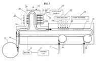
FIG. 1 is a somewhat schematic plan view of a sterile filling machine embodying the present invention. - In
FIG. 1 , a sterile filling machine ("SFM") embodying the present invention is indicated generally by the reference numeral 10. In the currently preferred embodiment of the invention, the SFM 10 is used to fill vials or syringes for containing medicaments, such as vaccines or pharmaceutical products. However, as may be recognized by those of ordinary skill in the pertinent art based on the teachings herein, the SFM 10 equally may be used for filling any of numerous other types of containers or delivery devices with the same or other substances, such as cosmetics and food products. The SFM 10 comprises aninfeed unit 12 for holding the vials, syringes orother containers 14 to be delivered into the SFM. In the illustrated embodiment of the present invention, the infeedunit 12 is in the form of a rotary table that holds a plurality of vials, syringes orother containers 14, and delivers the containers at a predetermined rate into the SFM. As may be recognized by those of ordinary skill in the pertinent art based on the teachings herein, the infeedunit 12 may take the form of any of numerous devices that are currently, or later become known for performing the function of the infeedunit 12, such as any of numerous different types of vibratory feed drives, or "pick and place" robotic systems. - Prior to installing the vials or
other containers 14 on the infeedunit 12, the sealed containers (e.g., the empty vials with the stoppers sealed thereto) are preferably sterilized, such as by exposing the containers to gamma radiation, in a manner known to those of ordinary skill in the pertinent art. In addition, the vial assemblies or other sealed, empty containers, may be enclosed, sterilized, and transported to the SFM 10 in accordance with the teachings ofU.S. Patent No. 5,186,772 , entitled "Method of Transferring Articles, Transfer Pocket And Enclosure", andU.S. Patent Application Serial No. 10/241,249, filed September 10, 2002 other containers 14 are sterilized again by e-beam radiation in order to further ensure absolute sterility of the requisite surfaces prior to filling and sealing, as described further below. - A
conveyor 16 is coupled to the infeedunit 12 for receiving the vials orother containers 14 delivered by the infeed unit and for transporting the vials or other containers at a predetermined rate through the SFM 10 in the directions indicated by the arrows inFIG. 1 . In the illustrated embodiment of the present invention, theconveyor 16 preferably transports thecontainers 14 in a single file relative to each other. In the event thecontainers 14 are vials, each vial preferably defines a substantially "diabolo" shape formed by a base, a cap and a body extending between the base and cap, wherein the base and cap define a diameter or width that is greater than that of the body. The diabolo shape may facilitate securing and otherwise transporting the vials through the SFM 10. Vials of this type are disclosed in co-pendingU.S. Provisional Patent Application Serial No. 60/408,068, filed September 3, 2002 U.S. Patent Application Serial No. 29/166,810, filed September 3, 2002 - The
conveyor 16 may take the form of any of numerous different types of conveyers that are currently, or later become known, for performing the functions of the conveyor described herein. For example, the conveyor may take the form of a vibratory feed drive, or may take the form of an endless conveyor belt including, for example, a plurality of receptacles, such as cleats, for receiving or otherwise holding the vials orother containers 14 at predetermined positions on the conveyor. Theconveyor 16 is drivingly connected to a motor or othersuitable drive source 15, which is controlled by a computer orother control unit 17 to start, stop, control the speed, and otherwise coordinate operation of the conveyor with the other components of the SFM. - The SFM 10 further includes an e-beam and
needle filling assembly 18 comprising ane-beam housing 20, at least onee-beam source 22, and aneedle filling station 24 mounted within the e-beam housing. Thee-beam source 22 may be any of numerous different types of e-beam sources that are currently, or later become known, for performing the function of thee-beam source 22 described herein. E-beam radiation is a form of ionizing energy that is generally characterized by its low penetration and high dose rates. The electrons alter various chemical and molecular bonds upon contact with an exposed product, including the reproductive cells of microorganisms, and therefore e-beam radiation is particularly suitable for sterilizing vials, syringes and other containers for medicaments or other sterile substances. As indicated by the arrows inFIG. 1 , thee-beam source 22 produces anelectron beam 26 that is formed by a concentrated, highly charged stream of electrons generated by the acceleration and conversion of electricity. Preferably, theelectron beam 26 is focused onto a penetrable surface of eachcontainer 14 for piercing by a needle to thereby fill the container with a medicament or other substance. For example, in the case of vials, such as the vials including resealable stoppers as described, for example, in the above-mentioned co-pending patent applications, theelectron beam 26 is focused onto the upper surface of the stopper to sterilize the penetrable surface of the stopper prior to insertion of the filling needle therethrough. In addition, reflective surfaces may be mounted on opposite sides of the conveyor relative to each other, or otherwise in a manner known to those of ordinary skill in the pertinent art based on the teachings herein, to reflect the e-beam, and/or the reflected and scattered electrons of the e-beam, onto the sides of the vials orother containers 14 to sterilize these surfaces as well. Alternatively, or in combination with such reflective surfaces, more than onee-beam source 22 may be employed, wherein each e-beam source is focused onto a respective surface or surface portion of the vials orother containers 14 to ensure sterilization of each surface or surface area of interest. - The
e-beam housing 20 is constructed in a manner known to those of ordinary skill in the pertinent art based on the teachings herein to define ane-beam chamber 28 and means for preventing leakage of the electrons out of the chamber in accordance with applicable safety standards. As shown inFIG. 1 , theconveyor 16 defines an approximately U-shaped path within thee-beam chamber 28, wherein the first leg of the U defines an inlet section and the portion of the chamber onto which the e-beam 26 is directed. In the currently preferred embodiment of the present invention, the current, scan width, position and energy of the e-beam 26, the speed of theconveyor 16, and/or the orientation and position of any reflective surfaces, are selected to achieve at least about a 3 log reduction, and preferably at least about a 6 log reduction in bio-burden testing on the upper surface of the vial's or other container's resealable stopper, i.e., the surface of the stopper defining the penetrable region that is pierced by a filling needle to fill the vial. In addition, as an added measure of caution, one or more of the foregoing variables also are preferably selected to achieve at least about a 3 log reduction on the sides of the vial or other container, i.e., on the surfaces of the vial that are not pierced by the needle during filling. These specific levels of sterility are only exemplary, however, and the sterility levels may be set as desired or otherwise required to validate a particular product under, for example, United States FDA or applicable European standards, such as the applicable Sterility Assurance Levels ("SAL"). - The e-beam and
needle filling assembly 18 also preferably includes means 25 for visually inspecting the fillingstation 24. This means may take the form of a beta-barrier window (i.e., a window that blocks any e-beam radiation but permits visual inspection therethrough), and/or a CCD, video or other camera mounted within the housing for transmitting to an external monitor (not shown) images of the fillingstation 24. As may be recognized by those of ordinary skill in the pertinent art based on the teachings herein, these particular devices are only exemplary, and any of numerous other devices that are currently, or later become known, for performing the function of permitting visual inspection equally may be employed. - As shown in
FIG. 1 , theneedle filling station 24 is mounted on the opposite leg, or outlet side of the U-shaped conveyor path within thee-beam chamber 28. In the illustrated embodiment of the present invention, theneedle station 24 includes a plurality ofneedles 30 or other filling members mounted over theconveyor 16, wherein each needle is drivingly mounted over the conveyor in the same manner as described, for example, in the above-mentioned co-pending patent applications. Accordingly, eachneedle 30 is movable into and out of engagement with the resealable stoppers to pierce the stoppers and fill the vials orother containers 14 with a medicament or other substance to be contained therein, and to then withdraw the needle upon filling the vial or other container. In the illustrated embodiment, theneedle filling station 24 includes a bank of sixneedles 30 mounted in line with each other and overlying theconveyor 16 to allow the simultaneous piercing and in-line filling of six vials or other containers. Theneedles 30 may be mounted on a common drive unit, or each needle may be individually actuatable into and out of engagement with the resealable stoppers of the vials orother containers 14. As may be recognized by those of ordinary skill in the pertinent art based on the teachings herein, theneedle filling station 24 may include any desired number ofneedles 30, or may be mounted or driven in any of numerous different ways that are currently, or later become known, for performing the functions of the needle filling station described herein. Similarly, the SFM 10 may include a plurality ofneedle filling stations 24 mounted within thesame e-beam chamber 28, or a plurality of e-beam and needle filling assemblies, in order to increase or otherwise adjust the overall throughput of the SFM 10. Preferably, thee-beam housing 20 defines a port 31 or other removable passageway to allow access to and/or repair and replacement of theneedle filling station 24. Eachneedle 30 is connected in fluid communication to asubstance source 33 by one ormore filling lines 35 for receiving therefrom a medicament of other substance to be filled into the vials orother containers 14. Thesubstance source 33 is preferably mounted external to thee-beam chamber 28, and the filling line(s) 35 connected between thesubstance source 33 and needles 30 are protected by suitable shielding, an electron trap, and/or other arrangement that is currently, or later becomes known to those of ordinary skill in the pertinent art, to prevent radiation within thee-beam chamber 28 from degrading or otherwise damaging the substance flowing through the line(s) 35 from the substance source 31 to theneedles 30. - As can be seen in
FIG. 1 , the e-beam andneedle filling assembly 18 is configured so that theneedles 30 of the needle filling station are mounted within thee-beam chamber 28. As a result, the free electrons within the e-beam chamber will impinge upon theneedles 30. This, in combination with operation of the e-beam 26 which sterilizes the air throughout the e-beam chamber, functions to sterilize the needles and/or maintain the sterility of the needles throughout the filling process. Preferably, the current, scan width, relative position and energy of the e-beam 26, and/or the orientation and position of any reflective surfaces, are selected to achieve at least about a 3 log reduction, and preferably at least about a 6 log reduction in bio-burden testing on the external surfaces of theneedles 30, including but not necessarily limited to, the surfaces of the needles that contact the resealable stoppers of the vials orother containers 14. Further, these levels of sterility are achievable within the shadows of theneedles 30 relative to thee-beam source 22 due to the electronic cloud of e-beam radiation formed within and around the needles. These specific levels of sterility are only exemplary, however, and the sterility levels may be set as desired or otherwise required to validate a particular product under, for example, United States FDA or applicable European standards, such as the applicable SAL. - Since the containers or other vials are filled within the
e-beam chamber 28, there is virtually no risk that the containers will become contaminated between e-beam sterilization and filling. If desired, the air within the e-beam chamber may be ionized to promote multiplication of the free electrons and further enhance the sterility of the filling station. Another advantage of the SFM of the present invention is that a laminar flow of air over the needles during filling may be unnecessary to achieve the requisite level of sterility. In addition, this feature of the present invention may further obviate the need for a laminar flow of air over the resealable stoppers during laser or other thermal sealing of the stoppers. In the illustrated embodiment of the present invention, there may be little, if any concern, that the filled vials or other containers will become contaminated during the brief period of transportation between the needle filling and laser sealing stations. Furthermore, this feature of the invention obviates any need for an isolator, as found in many prior art sterile filling machines. - The SFM 10 further includes a
laser sealing station 32 mounted over theconveyor 16 immediately downstream the outlet of the e-beam andneedle filling assembly 18. In the illustrated embodiment of the invention, thelaser sealing station 32 preferably includes a plurality of lasers, each mounted over a respective vial orother container 14 for transmitting arespective laser beam 34 onto the vial to heat seal the needle aperture in the resealable stopper. In the illustrated embodiment of the present invention, each laser is a diode laser fiber-optically coupled to a respective outlet port overlying the conveyor and focused onto a respective stopper position on the conveyor. For example, the lasers may take the form of the fiber coupled diode laser units manufactured by Semiconductor Laser International Corp. of Binghamton, NY, USA. A significant advantage of this type of laser system is that the lasers may be mounted remote from thelaser sealing station 32 and mounted, for example, outside of any enclosure for the laser sealing station. As a result, any laser repair or replacement may be performed outside of the laser sealing or other enclosure facilitating a significantly less expensive and time consuming procedure than if the laser were mounted within the enclosure. Thelaser sealing station 32 also preferably includes a smoke removal unit of a type known to those of ordinary skill in the pertinent art for removing any smoke, vapors or gases generated upon heat sealing the stoppers. As may be recognized by those of ordinary skill in the pertinent art based on the teachings herein, other types of laser, radiation, or other energy sources that are currently or later become known equally may be used to heat seal the penetrated regions of the stoppers. - In the illustrated embodiment of the invention, each resealable stopper is formed of a thermoplastic material defining a needle penetration region that is pierceable with a needle to form a needle aperture therethrough, and is heat resealable to hermetically seal the needle aperture by applying laser radiation at a predetermined wavelength and power thereto. Each stopper comprises a thermoplastic body defining (i) a predetermined wall thickness in an axial direction thereof, (ii) a predetermined color and opacity that substantially absorbs the laser radiation at the predetermined wavelength and substantially prevents the passage of the radiation through the predetermined wall thickness thereof, and (iii) a predetermined color and opacity that causes the laser radiation at the predetermined wavelength and power to hermetically seal the needle aperture formed in the needle penetration region thereof in a predetermined time period and substantially without burning the needle penetration region (i.e., without creating an irreversible change in molecular structure or chemical properties of the material). In a currently preferred embodiment, the predetermined time period is approximately 2 seconds, and is most preferably less than or equal to about 1.5 seconds. Also in a currently preferred embodiment, the predetermined wavelength of the laser radiation is about 980 nm, and the predetermined power of each laser is preferably less than about 30 Watts, and most preferably less than or equal to about 10 Watts, or within the range of about 8 to about 10 Watts. Also in the currently preferred embodiment, the predetermined color of the material is gray, and the predetermined opacity is defined by a dark gray colorant added to the stopper material in an amount within the range of about 0.3% to about 0.6% by weight. In addition, the thermoplastic material may be a blend of a first material that is preferably a styrene block copolymer, such as the materials sold under either the trademarks KRATON or DYNAFLEX, and a second material that is preferably an olefin, such as the materials sold under either the trademarks ENGAGE or EXACT. In one embodiment of the invention, the first and second materials are blended within the range of about 50:50 by weight to about 90:10 by weight (i.e., first material : second material). In one embodiment of the invention, the blend of first and second materials is about 50:50 by weight. The benefits of the preferred blend over the first material by itself are improved water or vapor barrier properties, and thus improved product shelf life; improved heat sealability; a reduced coefficient of friction; improved moldability or mold flow rates; and a reduction in hystereses losses. Further, if desired, the material may include a medical grade silicone or other suitable lubricant to facilitate preventing the formation of particles upon penetrating the resealable stoppers with the needles. As may be recognized by those skilled in the pertinent art, however, these numbers and materials are only exemplary, and may be changed if desired or otherwise required in a particular system.
- As shown in
FIG. 1 , the SFM 10 includes one or moreother stations 36 located downstream of thelaser sealing station 32. Theother stations 36 may include a vision system of a type known to those of ordinary skill in the pertinent art for inspecting each laser or other seal, a level detection system for detecting the level of fluid or other substance within each vial orother container 14 to ensure that it is filled to the correct level, and a labeling station. In addition, as shown inFIG. 1 , the SFM 10 includes a rejection unit 38 for pulling off of the conveyer any vials orother containers 14 that are defective as detected, for example, by the laser or other seal inspection, level detection inspection, or due to mislabeling or defective labeling. Then, the acceptable vials or other containers are removed by adischarge unit 40 for discharging the vials or other containers into acollection unit 42 for packing and shipping. The rejection and discharge units may take the forms of star wheels, pick and place robots, or any of numerous other devices that are currently or later become known for performing the functions of these units described herein. - A significant advantage of the present invention is that it enables true sterile filling and not only aseptic filling. Another advantage of the present invention is that the medicament or other substance is filled after subjecting the containers to gamma and direct e-beam radiation, thus preventing the radiation from degrading the medicament or other substance to be contained within the container. Yet another advantage of the present invention is that there is substantially zero possibility of contaminating the vials or other containers between the sterilization and filling steps.
- As may be recognized by those of ordinary skill in the pertinent art based on the teachings herein, numerous changes and modifications may be made to the above-described and other embodiments of the invention without departing from its scope as defined in the claims. For example, the form and configuration of many of the components of the SFM disclosed herein may change, or any number of stations may be added to the SFM to provide additional functionality. In addition, the containers may take the form of any of numerous different vials, syringes or other containers. Accordingly, this detailed description of preferred embodiments is to be taken in an illustrative as opposed to a limiting sense.
- The application is showing the following aspects:
- 1. A method for sterile filling a container with a substance, wherein the container includes a heat resealable stopper and a chamber for receiving the substance therein, the method comprising the steps of: sealing the stopper to the container; transporting the sealed, empty containers through an e-beam chamber; directing an electron beam within the e-beam chamber onto a penetrable surface of the stopper to sterilize the penetrable surface; introducing a needle within the e-beam chamber through the sterilized penetrable surface of the stopper; introducing through the needle a substance into the chamber of the container; withdrawing the needle from the stopper upon introducing the substance through the needle and into the chamber; transporting the filled containers out of the e-beam chamber; and applying energy to the penetrated surface of the stopper and hermetically sealing same.
- 2. A method as defined in aspect 1, further comprising the step of subjecting the sealed, empty container to radiation capable of penetrating through the stopper and chamber and sterilizing the container prior to transporting the container through the e-beam chamber.
- 3. A method as defined in aspect 2, wherein the step of subjecting the sealed container to radiation capable of penetrating through the stopper and chamber includes subjecting the container to gamma radiation.
- 4. A method as defined in aspect 1, further including the step of impinging e-beam radiation onto the needle within the e-beam chamber to maintain the needle sterile during filling of a plurality of containers.
- 5. A method as defined in aspect 1, wherein the step of applying energy to the penetrated surface of the stopper includes transmitting radiation onto the penetrated surface of the stopper to hermetically seal any needle aperture formed within the stopper.
- 6. A method as defined in aspect 1, wherein the substance is a medicament.
- 7. A method as defined in aspect 1, wherein at least one of the current, scan width, position and energy of the electron beam is selected to achieve at least about a 3 log reduction in bio-burden on the penetrable surface of the stopper.
- 8. A method as defined in aspect 7, wherein at least one of the current, scan width, position and energy of the electron beam is selected to achieve at least about a 6 log reduction in bio-burden on the penetrable surface of the stopper.
- 9. A method as defined in aspect 1, further comprising the step of introducing a preservative-free medicament through the needle and into the chamber of the container.
- 10. A method as defined in aspect 1, further comprising the step of providing a stopper having a needle penetration region that defines a predetermined color and opacity that substantially absorbs laser radiation at a predetermined wavelength and substantially prevents the passage of said laser radiation through a predetermined wall thickness thereof.
- 11. A method as defined in aspect 1, further comprising the step of providing a stopper having a needle penetration region defining a predetermined color and opacity that causes laser radiation at a predetermined wavelength and power to hermetically seal a needle aperture formed in the needle penetration region thereof in a predetermined time period.
- 12. A method as defined in aspect 1, further comprising the step of providing a conveyor within the e-beam chamber and transporting the container on the conveyor through the e-beam chamber, and providing at least one reflective surface adjacent to the conveyor for reflecting electron beam radiation onto at least one side of the container.
- 13. A method as defined in aspect 1, further comprising the step of providing a plurality of e-beam sources and directing an electron beam from each e-beam source into a respective region of the e-beam chamber.
- 14. A method as defined in aspect 13, further comprising the step of focusing each of a plurality of e-beam sources onto a respective surface area of the container.
- 15. A method as defined in aspect 1, further comprising the step of transporting the container through the e-beam chamber along a path defining a first leg and a second leg, focusing the electron beam onto the penetrable surface of the stopper within the first leg of the path, and introducing the needle through the sterilized penetrable surface of the stopper within the second leg of the path.
- 16. A method as defined in
aspect 15, wherein the path is approximately u-shaped, the first leg is a one leg of the u-shaped path, and the second leg is another leg of the u-shaped path. - 17. A method as defined in aspect 1, further comprising the step of drivingly mounting a plurality of needles within the e-beam chamber, driving the plurality of needles into engagement with a plurality of resealable stoppers and piercing the stoppers, and introducing the substance through the needles and into the chambers of the containers.
- 18. A method as defined in aspect 1, further comprising the step of ionizing air within the e-beam chamber for sterilizing a surface of the needle.
- 19. An apparatus for sterile filling a container with a substance, wherein the container includes a heat resealable stopper and a chamber for receiving the substance therein, the apparatus comprising: an e-beam chamber for receiving the container therein; an e-beam source for directing an electron beam within the e-beam chamber onto a penetrable surface of the stopper to sterilize the penetrable surface; a needle movably mounted within the e-beam chamber, wherein the needle is movable into and out of engagement with the resealable stopper for piercing the resealable stopper and introducing a substance through the stopper and into the sealed chamber of the container; and an energy source connectable in thermal communication with the penetrable surface of the resealable stopper for applying energy to the penetrable surface after withdrawing the needle therefrom to hermetically seal same.
- 20. An apparatus as defined in aspect 19, further comprising a first radiation source located external to the e-beam chamber for generating radiation capable of penetrating through the stopper and chamber of the container and sterilizing the container prior to transporting the container through the e-beam chamber.
- 21. An apparatus as defined in
aspect 20,wherein the radiation source is a gamma radiation source. - 22. An apparatus as defined in aspect 19, wherein the e-beam source and the needle located within the e-beam chamber are positioned relative to each other to cause e-beam radiation from the e-beam source to impinge on the needle and maintain needle sterility during filling of a plurality of containers.
- 23. An apparatus as defined in aspect 19, further comprising a second radiation source located outside of the e-beam chamber and configured to transmit radiation at a predetermined wavelength and power onto the stopper to hermetically seal a region of the stopper penetrated by the needle.
- 24. An apparatus as defined in aspect 23, wherein the second radiation source is a laser that transmits laser radiation at a predetermined wavelength.
- 25. An apparatus as defined in aspect 23, further comprising a container including a heat resealable stopper and a chamber for receiving the substance therein, wherein the stopper includes a needle penetration region that defines a predetermined color and opacity that substantially absorbs laser radiation at said predetermined wavelength and substantially prevents the passage of said laser radiation through a predetermined wall thickness thereof.
- 26. An apparatus as defined in
aspect 25, wherein the needle penetration region of the stopper defines a predetermined color and opacity that causes laser radiation at the predetermined wavelength and power to hermetically seal a needle aperture formed in the needle penetration region thereof in a predetermined time period. - 27. An apparatus defined in aspect 19, further comprising a conveyor extending within the e-beam chamber, a motor drivingly coupled to the conveyor for moving the conveyor and, in turn, transporting the container on the conveyor through the e-beam chamber, and a control unit coupled to the e-beam source and the motor, wherein the control unit controls at least one of the current, scan width, and energy of the e-beam source and the speed of the conveyor to achieve at least about a 3 log reduction in bio-burden on the penetrable surface of the stopper.
- 28. An apparatus defined in
aspect 24, wherein the control unit controls at least one of the current, scan width, and energy of the e-beam source and the speed of the conveyor to achieve at least about a 6 log reduction in bio-burden on the penetrable surface of the stopper. - 29. An apparatus as defined in aspect 19, further comprising a conveyor extending within the e-beam chamber for transporting a container on the conveyor through the e-beam chamber, and at least one reflective surface located adjacent to the conveyor for reflecting electron beam radiation onto at least one side of the container.
- 30. An apparatus as defined in aspect 19, further comprising a plurality of e-beam sources, each directing an electron beam into a respective region of the e-beam chamber.
- 31. An apparatus as defined in
aspect 30, wherein each e-beam source focuses its electron beam onto a respective surface area of the container. - 32. An apparatus as defined in aspect 19, further comprising a container path extending within the e-beam chamber for transporting the container along the path and through the e-beam chamber, wherein the path defines a first leg and a second leg, the electron beam is focused onto the penetrable surface of the stopper within the first leg of the path, and the needle is movably mounted on the second leg of the path for penetrating the sterilized penetrable surface of the stopper within the second leg of the path.
- 33. An apparatus as defined in
aspect 32, wherein the path is approximately u- shaped, the first leg is a one leg of the u-shaped path, and the second leg is another leg of the u- shaped path. - 34. An apparatus as defined in aspect 19, further comprising a plurality of needles drivingly mounted within the e-beam chamber, wherein each needle is drivable into and out of engagement with a resealable stopper of a respective container.
- 35. An apparatus as defined in aspect 19, further comprising a laser source for transmitting laser radiation at a predetermined wavelength and power, and a container including a heat resealable stopper and a chamber for receiving the substance therein, wherein the resealable stopper includes a thermoplastic body defining (i) a predetermined wall thickness in an axial direction thereof, (ii) a predetermined color and opacity that substantially absorbs the laser radiation at the predetermmed wavelength and substantially prevents the passage of the radiation through the predetermined wall thickness thereof, and (iii) a predetermined color and opacity that causes the laser radiation at the predetermined wavelength and power to hermetically seal a needle aperture formed in the needle penetration region thereof in a predetermined time period.
- 36. An apparatus as defined in
aspect 35, wherein the predetermined time period is less than or equal to approximately 2 seconds. - 37. An apparatus as defined in
aspect 35, wherein the predetermined color of the material is gray, and the predetermined opacity is defined by a dark gray colorant added to the stopper material in an amount within the range of about 0.3 percent to about 0.6 percent by weight. - 38. An apparatus for sterile filling a container with a substance, wherein the container includes a heat resealable stopper and a chamber for receiving the substance therein, the apparatus comprising: an e-beam chamber for receiving the container therein; first means for directing an e-beam beam within the e-beam chamber onto a penetrable surface of the stopper to sterilize the penetrable surface; second means located within the e-beam chamber and movable into and out of engagement with the resealable stopper for piercing the resealable stopper and introducing a substance through the stopper and into the sealed chamber of the container; and third means for applying energy to the penetrable surface of the resealable stopper after with drawing the second means therefrom to hermetically reseal the penetrable surface.
- 39. An apparatus as defined in aspect 38, wherein the first means is an e-beam source.
- 40. An apparatus as defined in aspect 38, wherein the second means is a needle.
- 41. An apparatus as defined in aspect 38, wherein the third means is a laser.
- 42. An apparatus as defined in aspect 38, further comprising fourth means for subjecting the sealed, empty container to radiation capable of penetrating through the stopper and chamber and sterilizing the container prior to transporting the container through the e- beam chamber.
- 43. An apparatus as defined in aspect 38, wherein the first means and the second means are configured relative to each other to achieve at least about a 3 log reduction in bio- burden on an external surface of the second means
Claims (23)
- A method comprising the following steps:providing a plurality of devices (14), wherein each device (14) includes a penetrable and resealable portion, and a sealed empty chamber in fluid communication with the penetrable and resealable portion;transporting the plurality of devices (14) on a conveyor (16) and performing the steps of:sterilizing at least a portion or surface of the devices (14) with an electron beam (26);introducing at least one filling member (30) through the penetrable and resealable portions of the devices (14);introducing through the at least one filling member (30) a substance into the chambers of the devices (14);withdrawing the at least one filling member (30) from the penetrable and resealable portions; andresealing the penetrable and resealable portions and sealing the substance within the devices (14).
- A method as defined in claim 1, further comprising moving the conveyor (16) and holding the devices (14) in predetermined positions thereon.
- A method as defined in claim 2, further comprising holding the devices (14) in the predetermined positions on the conveyor (16) with a plurality of receptacles or cleats.
- A method as defined in claim 2 or 3, further comprising moving the conveyor (16) with a drive source, such as a motor, drivingly connected to the conveyor (16), and controlling the drive source with a control unit to start, stop and control the speed of the conveyor (16).
- A method as defined in any of claims 1-4, wherein the resealing step includes transmitting or applying radiation or energy onto the penetrated surfaces of the penetrable and resealable portions of the devices (14).
- A method as defined in claim 5, further comprising transporting the devices (14) on the conveyor (16) to a filling station (24) including therein the at least one filling member (30), and transporting the devices on the conveyor (16) from the filling station (24) to a resealing station (32) and transmitting or applying the radiation or energy onto the penetrated surfaces within the resealing station (32) and resealing same.
- A method as defined in claim 5 or 6, further comprising the step of providing at least one laser for transmitting or applying the radiation or energy onto the penetrated surfaces.
- A method as defined in any of claims 5-7, further comprising providing the penetrable and resealable portion with a penetration region defining a predetermined color and opacity that causes laser radiation at a predetermined wavelength and power to hermetically seal an aperture formed in the penetration region thereof in a predetermined time period of less than or equal to about 2 seconds.
- A method as defined in any of claims 1-8, wherein the step of sterilizing at least a portion of the devices (14) includes directing the electron beam (26) onto said portion or surface of the devices (14).
- A method as defined in any of claims 1-9, further comprising drivingly mounting the at least one filling member (30) over the conveyor (16), and wherein the step of introducing the at least one filling member (30) through the penetrable and resealable portions comprises driving the at least one filling member (30) into engagement with the plurality of penetrable and resealable portions and piercing such.
- A method as defined in any of claims 1-10, wherein the step of introducing a substance into the chambers of the devices (14) comprises introducing a sterile substance, such as a sterile medicament, for example, a vaccine or pharmaceutical product, a cosmetic and/or a food product.
- A method as defined in any of claims 1-11, wherein each device (14) defines a base, a cap, and a body extending between the base and cap, wherein each of the base and cap defines a diameter or width that is greater than that of the body.
- A system for sterile filling devices (14) with a substance, wherein each device (14) includes a penetrable and resealable portion and a chamber for receiving the substance therein, comprising:a motorized conveyor (16) that transports the devices along a conveyor path;at least one e-beam source (22) located along the conveyor path that sterilizes at least a portion or surface of the devices (14);at least one filling member (30) movably mounted relative to the conveyor path, wherein the at least one filling member (30) is movable into and out of engagement with the penetrable and resealable portions of the devices (14) and is configured to pierce such penetrable and resealable portions and introduce a substance therethrough and into the sealed chambers of the device (14); andat least one radiation or energy source for sealing resulting penetration holes formed by the at least one filling member.
- A system as defined in claim 13, wherein the at least one e-beam source (22) is located in an e-beam chamber (28) and directs an electron beam (26) onto said portions or surfaces of the devices (14) to be sterilized.
- A system as defined in any of claims 13 or 14, wherein the at least one radiation or energy source is configured to transmit laser radiation at a predetermined wavelength and power onto the penetrated surfaces of the devices (14).
- A system as defined in any of claims 13-15, further comprising a plurality of said devices (14).
- A system as defined in any of claims 13-16, wherein each penetrable and resealable portion includes a thermoplastic body defining (i) a predetermined wall thickness in an axial direction thereof, (ii) a predetermined color and opacity that substantially absorbs laser radiation at the predetermined wavelength and substantially prevents the passage of the radiation through the predetermined wall thickness thereof, and (iii) a predetermined color and opacity that causes the laser radiation at the predetermined wavelength and power to hermetically seal a needle aperture formed in the needle penetration region thereof in a predetermined time period.
- A system as defined in any of claims 13-17, wherein each device (14) defines a base, a cap, and a body extending between the base and cap, wherein each of the base and cap defines a diameter or width that is greater than that of the body.
- A system as defined in any of claims 13-18, wherein the conveyor (16) holds the devices (14) in predetermined positions thereon, wherein preferably the conveyor (16) includes a plurality of receptacles or cleats for receiving or otherwise holding the devices (14) in the predetermined positions thereon.
- A system as defined in any of claims 13-19, wherein the at least one filling member (30) is mounted over the conveyor (16).
- A system as defined in any of claims 13-20, further comprising a substance source (33) connectible in fluid communication with the at least one filling member (30) for providing substance to be introduced therethrough and into the chambers of the devices (14), wherein preferably the substance is a sterile substance, such as a sterile medicament, for example, a vaccine or pharmaceutical product, a cosmetic and/or a food product.
- A system as defined in any of claims 13-21, further comprising a filling station (24) including a plurality of said at least one filling member (30).
- A system as defined in any of claims 13-22, further comprising a resealing station (32) including a plurality of said at least one radiation or energy source.
Applications Claiming Priority (2)
| Application Number | Priority Date | Filing Date | Title |
|---|---|---|---|
| US39021202P | 2002-06-19 | 2002-06-19 | |
| EP03761225A EP1517834B1 (en) | 2002-06-19 | 2003-06-19 | Sterile filling machine having needle filling station within e-beam chamber |
Related Parent Applications (1)
| Application Number | Title | Priority Date | Filing Date |
|---|---|---|---|
| EP03761225.6 Division | 2003-06-19 |
Publications (2)
| Publication Number | Publication Date |
|---|---|
| EP2433871A2 true EP2433871A2 (en) | 2012-03-28 |
| EP2433871A3 EP2433871A3 (en) | 2012-07-11 |
Family
ID=30000527
Family Applications (2)
| Application Number | Title | Priority Date | Filing Date |
|---|---|---|---|
| EP03761225A Expired - Lifetime EP1517834B1 (en) | 2002-06-19 | 2003-06-19 | Sterile filling machine having needle filling station within e-beam chamber |
| EP11194608A Withdrawn EP2433871A3 (en) | 2002-06-19 | 2003-06-19 | Sterile filling machine having needle filling station within e-beam chamber |
Family Applications Before (1)
| Application Number | Title | Priority Date | Filing Date |
|---|---|---|---|
| EP03761225A Expired - Lifetime EP1517834B1 (en) | 2002-06-19 | 2003-06-19 | Sterile filling machine having needle filling station within e-beam chamber |
Country Status (6)
| Country | Link |
|---|---|
| US (6) | US6929040B2 (en) |
| EP (2) | EP1517834B1 (en) |
| JP (2) | JP4782417B2 (en) |
| AU (1) | AU2003251594A1 (en) |
| CA (1) | CA2489804C (en) |
| WO (1) | WO2004000100A2 (en) |
Families Citing this family (51)
| Publication number | Priority date | Publication date | Assignee | Title |
|---|---|---|---|---|
| US7669390B2 (en) | 2004-03-08 | 2010-03-02 | Medical Instill Technologies, Inc. | Method for molding and assembling containers with stoppers and filling same |
| US20160068283A1 (en) * | 2000-02-11 | 2016-03-10 | Daniel Py | Method for Molding and Assembling Containers With Stoppers and Filling Same |
| US7707807B2 (en) | 2004-03-08 | 2010-05-04 | Medical Instill Technologies, Inc. | Apparatus for molding and assembling containers with stoppers and filling same |
| US6801070B2 (en) * | 2002-05-16 | 2004-10-05 | Micron Technology, Inc. | Measure-controlled circuit with frequency control |
| EP1517834B1 (en) | 2002-06-19 | 2012-05-23 | Medical Instill Technologies, Inc. | Sterile filling machine having needle filling station within e-beam chamber |
| CA2638781C (en) | 2002-09-03 | 2010-02-02 | Medical Instill Technologies, Inc. | Sealed containers and methods of making and filling same |
| GB0304386D0 (en) * | 2003-02-25 | 2003-04-02 | Glaxosmithkline Biolog Sa | Novel process |
| US7077176B2 (en) | 2003-04-28 | 2006-07-18 | Medical Instill Technologies, Inc. | Container with valve assembly for filling and dispensing substances, and apparatus and method for filling |
| EP1861313A2 (en) | 2005-03-11 | 2007-12-05 | Medical Instill Technologies, Inc. | Sterile de-molding apparatus and method |
| ES2524774T3 (en) | 2005-10-17 | 2014-12-12 | Medical Instill Technologies, Inc. | Apparatus and method of sterile demoulding |
| US7780023B2 (en) * | 2006-04-10 | 2010-08-24 | Medical Instill Technologies, Inc. | Ready to drink container with nipple and needle penetrable and laser resealable portion, and related method |
| EP2013113B1 (en) | 2006-04-24 | 2018-03-21 | Medical Instill Technologies, Inc. | Needle penetrable and resealable lyophilization device and related method |
| US7520108B2 (en) * | 2006-06-13 | 2009-04-21 | Tetra Laval Holdings & Finance Sa | Method of sterilizing packages |
| JP4940944B2 (en) * | 2006-12-28 | 2012-05-30 | 澁谷工業株式会社 | Container filling system |
| DE102007001970A1 (en) * | 2007-01-13 | 2008-07-17 | Khs Ag | Method and device for the sterilization of containers made of metal |
| DE102007003334A1 (en) * | 2007-01-17 | 2008-08-07 | Khs Ag | Method and device for the continuous sterilization of pouches |
| CN101284387B (en) * | 2007-04-12 | 2011-10-05 | 清华大学 | Method and apparatus using electron beam to perform log quarantine irradiation |
| DE102007017938C5 (en) * | 2007-04-13 | 2017-09-21 | Khs Gmbh | Container manufacturing apparatus and mold production method |
| DE102007029567A1 (en) * | 2007-06-26 | 2009-01-02 | Krones Ag | Sterilization with β radiation |
| EP2207427B1 (en) * | 2007-10-04 | 2017-05-03 | Medical Instill Technologies, Inc. | Apparatus and method for formulating and aseptically filling liquid products |
| DE102008001282A1 (en) * | 2008-04-21 | 2009-10-22 | Robert Bosch Gmbh | Method for closing containers by means of a closure in a gripping device |
| EP2657183B1 (en) * | 2008-05-20 | 2016-04-06 | Dai Nippon Printing Co., Ltd. | Beverage filling method |
| JP5270248B2 (en) * | 2008-08-01 | 2013-08-21 | タカタ株式会社 | Pretensioner, seat belt retractor having the pre tensioner, and seat belt device having the same |
| US8498729B2 (en) * | 2008-08-29 | 2013-07-30 | Smp Logic Systems Llc | Manufacturing execution system for use in manufacturing baby formula |
| DE102008045187A1 (en) * | 2008-08-30 | 2010-03-04 | Krones Ag | Electron beam sterilization for containers |
| IT1391065B1 (en) * | 2008-10-17 | 2011-11-18 | Co Ri M A S R L | MACHINE FOR FILLING VIALS |
| PL2456864T3 (en) | 2009-05-01 | 2016-04-29 | Promega Corp | Synthetic oplophorus luciferases with enhanced light output |
| CN102460179B (en) * | 2009-06-24 | 2014-07-16 | 株式会社Afc | Blood collection tube stocker and device for preparing blood collection tubes |
| GB2476288B (en) * | 2009-12-18 | 2014-05-14 | Univet Res Ltd | A method of manufacturing a medicinal product |
| FR2954935B1 (en) * | 2010-01-06 | 2012-04-20 | Hema | METHOD AND DEVICE FOR PROCESSING CONTAINERS |
| FR2956974B1 (en) * | 2010-03-05 | 2013-07-05 | Hema | METHOD AND DEVICE FOR MANUFACTURING FLEXIBLE STERILE POCKETS FILLED WITH A PRODUCT, IN PARTICULAR A THERAPEUTIC LIQUID |
| US20110265429A1 (en) * | 2010-04-28 | 2011-11-03 | Marietta Corporation | System and Method for Assembly of Packettes Having Closures |
| MX2013000382A (en) * | 2010-07-16 | 2013-09-02 | Stevanato Group Internat As | Manufacturing process for packing of injectables. |
| DE102010031800A1 (en) * | 2010-07-20 | 2012-01-26 | Krones Aktiengesellschaft | Arrangement and method for coupling a plurality of machine assemblies of a container treatment machine |
| DE102010049263A1 (en) * | 2010-10-25 | 2012-04-26 | Khs Gmbh | Method and equipment for sterile or aseptic filling and sealing of packaging |
| US9289522B2 (en) | 2012-02-28 | 2016-03-22 | Life Technologies Corporation | Systems and containers for sterilizing a fluid |
| EP2836433B1 (en) * | 2012-04-13 | 2018-10-03 | Dr. Py Institute, LLC | Modular filling apparatus and method |
| CN102991739B (en) * | 2012-10-11 | 2014-04-16 | 常熟威玛乳品机械有限公司 | Filling mechanism of automatic paper-cup ice cream filling machine |
| BR112015023625A2 (en) | 2013-03-15 | 2020-05-19 | Dr. Py Institute Llc | controlled unrated filling device and method |
| US9415885B2 (en) | 2013-03-15 | 2016-08-16 | Dr. Py Institute Llc | Device with sliding stopper and related method |
| DE102013106742A1 (en) * | 2013-06-27 | 2014-12-31 | Khs Gmbh | Device for forming packaging units |
| AU2014312012B2 (en) * | 2013-09-02 | 2018-08-09 | B.Braun Medical Inc. | Flexible container, system and method of manufacture |
| US9587215B2 (en) | 2014-08-07 | 2017-03-07 | General Electric Company | Devices, systems and methods for automated transfer of a sample |
| ITUB20151794A1 (en) * | 2015-07-01 | 2017-01-01 | Guala Pack Spa | STERILIZATION SYSTEM FOR FLEXIBLE BODY PACKAGING (POUCH) |
| USD829896S1 (en) | 2015-09-15 | 2018-10-02 | Dr. Py Institute Llc | Septum |
| EP3349713B1 (en) | 2015-09-15 | 2023-11-01 | Dr. Py Institute LLC | Septum that decontaminates by interaction with penetrating element |
| IT201800004068A1 (en) * | 2018-03-29 | 2019-09-29 | Marchesini Group Spa | MACHINE FOR FILLING AND CLOSING PHARMACEUTICAL CONTAINERS, SUCH AS SYRINGES, BOTTLES AND SIMILAR |
| KR20210006423A (en) * | 2018-05-07 | 2021-01-18 | 센트로닉스 인코포레이티드 | Generative fragrance design system |
| WO2019241014A1 (en) * | 2018-06-14 | 2019-12-19 | Curium Us Llc | Evacuation/fill station for radioactive fluid container production |
| CN112407469A (en) * | 2020-11-10 | 2021-02-26 | 北京图腾猎技科技有限公司 | Efficient food sterilization device and food sterilization method |
| DE102022107540A1 (en) | 2021-04-07 | 2022-10-13 | Guido Knobel | Process for filling a medicinal product |
Citations (1)
| Publication number | Priority date | Publication date | Assignee | Title |
|---|---|---|---|---|
| US5186772A (en) | 1985-11-30 | 1993-02-16 | Sumitomo Rubber Industries, Ltd. | Run-flat tire and rim assemblies for ATV |
Family Cites Families (155)
| Publication number | Priority date | Publication date | Assignee | Title |
|---|---|---|---|---|
| US2734649A (en) | 1956-02-14 | Moistureproof vial closure | ||
| US2061958A (en) | 1935-01-08 | 1936-11-24 | Chapman Harold Eric | Air filtering appliance for bottles |
| US2191447A (en) | 1937-04-21 | 1940-02-27 | Emery S Beardsley | Container closure |
| US2260997A (en) | 1937-08-20 | 1941-10-28 | Budd Edward G Mfg Co | Door for closed vehicles, especially for automobiles |
| US2503147A (en) | 1944-12-21 | 1950-04-04 | Applezweig Norman | Carpule filling machine |
| US2667986A (en) | 1951-12-22 | 1954-02-02 | Harold N Perelson | Self-sealing dispensing device |
| US2804224A (en) | 1954-04-15 | 1957-08-27 | Mead Johnson & Co | Blood bottle closure |
| US2797837A (en) | 1954-04-19 | 1957-07-02 | Roberts Charles Buford | Stopper for ampoules and the like |
| US2842276A (en) | 1955-08-02 | 1958-07-08 | Cutter Lab | Container closure |
| US2876775A (en) | 1955-10-03 | 1959-03-10 | Sr Courtland H Barr | Blood sample collection apparatus |
| US3092278A (en) | 1957-09-20 | 1963-06-04 | Astra Apotekarnes Kem Fab | Cap for a container for an injection liquid |
| US3193128A (en) | 1962-06-12 | 1965-07-06 | West Co | Container closure |
| US3278063A (en) | 1963-02-02 | 1966-10-11 | Faensen Kleinmetall | Sealing device |
| US3136440A (en) | 1963-06-25 | 1964-06-09 | Becton Dickinson Co | Self sealing pierceable stopper for sealed containers |
| US3340671A (en) | 1964-08-10 | 1967-09-12 | Carnation Co | Method of filling containers under aseptic conditions |
| US3358865A (en) | 1965-09-22 | 1967-12-19 | West Co | Container closure |
| US3392859A (en) | 1966-04-22 | 1968-07-16 | Albert M. Fischer | Perforable self-sealing container closure |
| US3480171A (en) | 1966-12-30 | 1969-11-25 | West Co | Container closure |
| US3424329A (en) | 1967-06-21 | 1969-01-28 | Schering Corp | Sealed injection vial |
| BE741479A (en) | 1969-11-10 | 1970-04-16 | ||
| US3637102A (en) | 1970-05-25 | 1972-01-25 | Continental Can Co | Closures for aseptic filled containers |
| US3780308A (en) * | 1971-06-07 | 1973-12-18 | Energy Sciences Inc | Process and apparatus for surface sterilization of materials |
| US3792794A (en) | 1971-10-04 | 1974-02-19 | Cutter Lab | Closure for containers |
| US3811591A (en) | 1971-10-19 | 1974-05-21 | New England Nuclear Corp | Dually sealable, non-leaking vial for shipping radioactive materials |
| US3826059A (en) | 1971-10-19 | 1974-07-30 | New England Nuclear Corp | Method of packaging radioactive materials |
| US3875012A (en) | 1974-01-30 | 1975-04-01 | Wadley Res Inst & Blood Bank | Apparatus and method for the detection of microbial pathogens |
| US4009654A (en) * | 1974-12-20 | 1977-03-01 | General Electric Company | Automatic modification of the print control in a printing device |
| JPS5217469U (en) | 1975-07-25 | 1977-02-07 | ||
| US3969527A (en) | 1975-07-28 | 1976-07-13 | E. R. Squibb & Sons, Inc. | CNS active compounds |
| US4048255A (en) | 1975-08-26 | 1977-09-13 | Abbott Laboratories | Blend of thermoelastic polymers with block radial polymers used as pharmaceutical sealing and resealing materials |
| US4041994A (en) | 1975-09-22 | 1977-08-16 | Horwitz Norman H | Dose dispenser for radioactive gas |
| US4039011A (en) * | 1976-03-26 | 1977-08-02 | Northwest Hardwoods, Inc. | Chipper saw |
| FI66807C (en) | 1977-05-09 | 1984-12-10 | Asicomo As | CAPSULE FOR BEHAOLLARLOCK AND FOAR FARANDE FOER TILLVERKNING AV DETSAMMA |
| CA1123792A (en) | 1977-07-05 | 1982-05-18 | Joseph D. Trizisky | Mercury sealable plug |
| US4235725A (en) | 1978-08-16 | 1980-11-25 | Owens-Illinois, Inc. | Sterile blood-collecting and separating device |
| JPS5749739Y2 (en) | 1978-08-25 | 1982-10-30 | ||
| US4251003A (en) | 1979-01-19 | 1981-02-17 | Toni Casutt | Bottle closing device |
| US4250611A (en) | 1979-04-19 | 1981-02-17 | Alza Corporation | Process for making drug delivery device with reservoir |
| JPS56119254A (en) | 1980-02-25 | 1981-09-18 | Takeda Chemical Industries Ltd | Rubber stopper for vial |
| GB2091229B (en) | 1980-12-19 | 1984-04-26 | Seven Holdings Ltd | Fitments for containers from which liquid is intended to be withdrawn by a hollow needle or tube |
| US4358539A (en) | 1981-03-20 | 1982-11-09 | Becton, Dickinson And Company | Throw-away subculturing device |
| US4364485A (en) | 1981-05-15 | 1982-12-21 | Schering Corporation | Injectable fluid container and method |
| FR2509689A1 (en) | 1981-07-17 | 1983-01-21 | Ceca Sa | Steam sterilised tap for aseptic transfer of contained liquid to flask - uses hollow piston to locate flask and push it onto hypodermic needle |
| US4423819A (en) | 1981-08-19 | 1984-01-03 | U.S. Clinical Products, Inc. | Flexible sterile closure system for containers |
| JPS5858057A (en) | 1981-10-02 | 1983-04-06 | テルモ株式会社 | Gasket body for therapeutic container |
| JPS5859749U (en) | 1981-10-16 | 1983-04-22 | オリンパス光学工業株式会社 | container cap |
| US4390111A (en) | 1982-02-08 | 1983-06-28 | Robbins Scientific Corporation | Sealable vial |
| FR2529531A1 (en) | 1982-07-01 | 1984-01-06 | Lyonnaise Bouchage | MEANS FOR CLOSING A CONTAINER OF THE TYPE COMPRISING AN ALUMINUM SHEET OR LIKE OPENER, FIXED BY BONDING OR WELDING ON THE SURROUNDING OF THE ORIFICE OF THE CONTAINER |
| USD279651S (en) | 1983-01-03 | 1985-07-16 | Carlisle Corporation, having a division Continental Carlisle | Combined container and closure |
| US4499148A (en) | 1983-01-10 | 1985-02-12 | Canton Bio-Medical Products, Inc. | Composite materials of silicone elastomers and polyolefin films, and method of making |
| US4664277A (en) | 1983-03-14 | 1987-05-12 | The West Company | Bonded closure assembly |
| US4635807A (en) | 1983-03-17 | 1987-01-13 | Schering Corporation | Stopper for sterile fluid containers |
| US4471879A (en) | 1983-08-04 | 1984-09-18 | The West Company | Metal overcap for pharmaceutical and similar containers |
| DE3579893D1 (en) | 1984-05-16 | 1990-10-31 | Cosmonor Sa | METHOD FOR COMPOSING UNIT QUANTITIES WITH PRE-FILLED SYRINGES OR PRE-FILLED SPRAYERS. |
| JPS6164253A (en) | 1984-09-07 | 1986-04-02 | テルモ株式会社 | Stopcock for medical container |
| US4652763A (en) * | 1985-03-29 | 1987-03-24 | Energy Sciences, Inc. | Electron-beam irradiation sterilization process |
| JPS61247459A (en) | 1985-04-25 | 1986-11-04 | テルモ株式会社 | Plug body for medical container |
| US4834152A (en) | 1986-02-27 | 1989-05-30 | Intelligent Medicine, Inc. | Storage receptacle sealing and transfer apparatus |
| SE456080B (en) | 1987-01-15 | 1988-09-05 | Rexinell Ab | DEVICE FOR CLOSING CONTAINERS |
| US4842028A (en) | 1987-05-13 | 1989-06-27 | Baxter International Inc. | Fluid transfer apparatus |
| US4815619A (en) | 1987-07-13 | 1989-03-28 | Turner Thomas R | Medicament vial safety cap |
| US4863453A (en) | 1987-12-22 | 1989-09-05 | Sherwood Medical Company | Sterile closure device |
| US4968625A (en) | 1988-02-01 | 1990-11-06 | Difco Laboratories | Centrifrugation vial and cluster tray |
| US5038839A (en) * | 1988-07-18 | 1991-08-13 | Takeda Chemical Industries, Ltd. | Filling apparatus |
| US4910435A (en) | 1988-07-20 | 1990-03-20 | American International Technologies, Inc. | Remote ion source plasma electron gun |
| US5247015A (en) | 1988-12-22 | 1993-09-21 | The West Company, Incorporated | Molded thermoplastic elastomer |
| US5009654A (en) | 1989-03-10 | 1991-04-23 | Baxter International Inc. | Sterile product and method for sterilizing and assembling such product |
| IT1229165B (en) | 1989-04-07 | 1991-07-22 | Leopardi Francesco Paoletti Se | DEVICE FOR CLOSING VACUUM TUBES FOR BLOOD COLLECTION. |
| US5341854A (en) | 1989-09-28 | 1994-08-30 | Alberta Research Council | Robotic drug dispensing system |
| US5088995A (en) | 1990-06-22 | 1992-02-18 | Baxter International Inc. | Port and closure assembly including a resealing injection site for a container |
| DE4103041A1 (en) | 1990-10-12 | 1992-04-16 | Alfred Von Schuckmann | CAP FOR AN INFUSION BOTTLE |
| US5129212A (en) * | 1990-11-08 | 1992-07-14 | Liqui-Box/B-Bar-B Corporation | Method and apparatus for automatically filling and sterilizing containers |
| US5085332B1 (en) | 1991-04-11 | 1994-04-05 | Gettig Technologies Inc | Closure assembly |
| DE4135470C2 (en) | 1991-10-28 | 1993-09-30 | Fes Kunststoff Gmbh | Plastic closure cap, in particular for glass containers in various fields of application |
| US5088612A (en) | 1991-06-10 | 1992-02-18 | Comar, Inc. | Vial cap |
| US5226462A (en) | 1991-07-26 | 1993-07-13 | Carl Richard A | Introducing measured amounts of liquid into receptacles |
| JPH0516659U (en) | 1991-08-06 | 1993-03-02 | 石田プレス工業株式会社 | Medicinal bottle lid |
| US5344036A (en) | 1992-06-04 | 1994-09-06 | Akzo N.V. | Container system |
| TW252081B (en) * | 1992-07-14 | 1995-07-21 | Eizai Co Ltd | |
| US5464111A (en) | 1993-03-03 | 1995-11-07 | Sterling Winthrop | Closure for medication container |
| US5612588A (en) | 1993-05-26 | 1997-03-18 | American International Technologies, Inc. | Electron beam device with single crystal window and expansion-matched anode |
| US5414267A (en) | 1993-05-26 | 1995-05-09 | American International Technologies, Inc. | Electron beam array for surface treatment |
| JP2702059B2 (en) | 1993-07-09 | 1998-01-21 | 扶桑薬品工業株式会社 | Method of closing mouth of synthetic resin infusion container |
| USD383214S (en) | 1993-08-18 | 1997-09-02 | Brennan V Jack | Combined cap and vial |
| USD389586S (en) | 1993-08-18 | 1998-01-20 | Brennan V Jack | Combined cap and vial |
| JPH0734858U (en) | 1993-12-09 | 1995-06-27 | 忠男 佐々 | Floating bag with Styrofoam |
| US5411065A (en) | 1994-01-10 | 1995-05-02 | Kvm Technologies, Inc. | Liquid specimen transfer apparatus and method |
| EP0746501B1 (en) | 1994-03-02 | 2001-07-04 | Tl Systems Corporation | Sterile vial filling apparatus |
| US5484566A (en) | 1994-03-07 | 1996-01-16 | Wheaton Inc. | Method of manufacture of a partially laminated rubber closure |
| FR2719018B1 (en) * | 1994-04-26 | 1996-07-12 | Py Daniel C | Method for filling a closed container under aseptic conditions. |
| CA2125811A1 (en) | 1994-06-14 | 1995-12-15 | Victor Daykin | Perforable cap for a biological specimen container |
| US5549141A (en) | 1994-07-19 | 1996-08-27 | Kvm Technologies, Inc. | Liquid container sample transfer method and apparatus |
| US5744087A (en) | 1994-09-26 | 1998-04-28 | Becton, Dickinson And Company | Medical articles and method therefor |
| US5647939A (en) | 1994-12-05 | 1997-07-15 | Integrated Liner Technologies, Inc. | Method of bonding a cured elastomer to plastic and metal surfaces |
| US5909032A (en) | 1995-01-05 | 1999-06-01 | American International Technologies, Inc. | Apparatus and method for a modular electron beam system for the treatment of surfaces |
| WO1996026702A1 (en) | 1995-03-02 | 1996-09-06 | Novo Nordisk A/S | Kit for storage and mixing of agents of which at least one is liquid |
| US5904677A (en) | 1995-07-13 | 1999-05-18 | Drummey; Thomas Hartnett | Sterile specimen capture device |
| FR2738232B1 (en) | 1995-09-04 | 1997-11-14 | Py Daniel C | METHOD FOR TRANSFERRING ARTICLES, POCKET AND ENCLOSURE FOR TRANSFER |
| CA2185494A1 (en) | 1995-09-27 | 1997-03-28 | Jean-Pierre Grimard | Resealable vial with connector assembly having a membrane and pusher |
| US5702019A (en) | 1995-09-27 | 1997-12-30 | Becton Dickinson France S.A. | Vial having resealable membrane assembly activated by a medical delivery device |
| DE29515681U1 (en) | 1995-10-02 | 1995-12-07 | Braun Melsungen Ag | Safety cap for containers |
| ES2159374T3 (en) | 1995-10-18 | 2001-10-01 | Daikyo Seiko Ltd | PLASTIC COVER AND ITS MANUFACTURING PROCEDURE. |
| SE506058C2 (en) * | 1996-02-28 | 1997-11-03 | Tetra Laval Holdings & Finance | Ways to sterilize closed packages |
| IT1287402B1 (en) | 1996-02-29 | 1998-08-06 | Bormioli Metalplast Spa | CAPSULE FOR THE SAFETY CLOSURE OF CONTAINERS |
| JPH1033636A (en) * | 1996-05-03 | 1998-02-10 | Yuyama Seisakusho:Kk | Medicine separately wrapping device, medicine bottle, and medicine testing method |
| DE19622689A1 (en) | 1996-06-05 | 1997-12-11 | Fresenius Ag | Tamper-evident closure for nozzle-like openings in containers |
| US6145688A (en) | 1996-07-17 | 2000-11-14 | Smith; James C. | Closure device for containers |
| JPH1045116A (en) * | 1996-07-30 | 1998-02-17 | Mitsubishi Heavy Ind Ltd | Equipment for sterilization/disinfection |
| AT404317B (en) | 1996-08-02 | 1998-10-27 | Greiner & Soehne C A | LOCKING DEVICE, DISCONNECTING DEVICE AND RECEIVING CONTAINER FOR A RECEIVING DEVICE |
| US5842321A (en) * | 1996-08-06 | 1998-12-01 | Advanced Mechanical Technologies, Inc. | System and apparatus for filling and capping a vial |
| US5931828A (en) | 1996-09-04 | 1999-08-03 | The West Company, Incorporated | Reclosable vial closure |
| US5901866A (en) | 1998-02-13 | 1999-05-11 | Comar Inc. | Break away overcap |
| US5718348A (en) | 1996-09-12 | 1998-02-17 | Comar, Inc. | Overcap assembly for gear finish vial |
| US5803284A (en) | 1996-09-27 | 1998-09-08 | Becton Dickinson And Company | Sterile closure assembly for sealing a medicament container |
| IT1289760B1 (en) * | 1996-12-17 | 1998-10-16 | Hospal Dasco Spa | SYSTEM FOR STERILIZATION OF MEDICAL PRODUCTS THROUGH BETA RAYS RADIATION. |
| JPH10234819A (en) | 1997-02-20 | 1998-09-08 | Nissho Corp | Rubber plug slipping prevention mechanism for vial |
| US6050435A (en) | 1997-03-28 | 2000-04-18 | Rexam Plastics, Inc. | Closure with integral self-sealing silicone valve and method for making same |
| DE19716846C1 (en) * | 1997-04-22 | 1998-11-19 | Bosch Gmbh Robert | Evacuation and closing device |
| USD439345S1 (en) | 1997-05-22 | 2001-03-20 | Abbott Laboratories | Container for use with an automatic analyzer |
| US5829594A (en) | 1997-06-27 | 1998-11-03 | Pro-Tech-Tube, Inc. | Protective enclosure for shipping and storing hazardous materials |
| JPH1143118A (en) | 1997-07-25 | 1999-02-16 | Dainippon Printing Co Ltd | Aseptic filling method for paper container for liquid |
| KR20010022303A (en) | 1997-07-30 | 2001-03-15 | 쿡 인코포레이티드 | Medical Fluid Flow Control Valve |
| US5902298A (en) | 1997-11-07 | 1999-05-11 | Bracco Research Usa | Medicament container stopper with integral spike access means |
| US5985962A (en) | 1997-12-05 | 1999-11-16 | Becton, Dickinson And Company | Composition and article of improved compression set |
| US6752965B2 (en) | 1998-03-06 | 2004-06-22 | Abner Levy | Self resealing elastomeric closure |
| EP1061975B1 (en) * | 1998-03-13 | 2004-02-11 | Becton, Dickinson and Company | Method for assembling and packaging medical devices |
| JP3649902B2 (en) * | 1998-04-08 | 2005-05-18 | 松下電器産業株式会社 | Manufacturing method of dome cover |
| US6681475B2 (en) | 1998-04-20 | 2004-01-27 | Becton Dickinson And Company | Method of sealing a medical container with a plastic closure |
| US5921419A (en) | 1998-05-04 | 1999-07-13 | Bracco Research Usa | Universal stopper |
| US6168039B1 (en) * | 1998-05-08 | 2001-01-02 | First Preference Products Corp. | Household product package |
| EP1044135B1 (en) | 1998-07-14 | 2002-10-09 | Amersham Health AS | Package comprising a container with a mouth |
| US7264771B2 (en) * | 1999-04-20 | 2007-09-04 | Baxter International Inc. | Method and apparatus for manipulating pre-sterilized components in an active sterile field |
| JP3142521B2 (en) | 1998-11-04 | 2001-03-07 | 大成プラス株式会社 | Needlestick stopcock and its manufacturing method |
| US6068150A (en) | 1999-01-27 | 2000-05-30 | Coulter International Corp. | Enclosure cap for multiple piercing |
| US6140657A (en) | 1999-03-17 | 2000-10-31 | American International Technologies, Inc. | Sterilization by low energy electron beam |
| US6568439B1 (en) | 1999-04-20 | 2003-05-27 | Jms Co., Ltd. | Container cap and liquid communication adapter |
| US6364864B1 (en) | 1999-06-03 | 2002-04-02 | Baxter International Inc. | Plastic containers having inner pouches and methods for making such containers |
| US6604561B2 (en) * | 2000-02-11 | 2003-08-12 | Medical Instill Technologies, Inc. | Medicament vial having a heat-sealable cap, and apparatus and method for filling the vial |
| JP2001235850A (en) * | 2000-02-24 | 2001-08-31 | Sony Corp | Method for designing photomask pattern, method for forming resist pattern and method for manufacturing semiconductor device |
| US6382441B1 (en) | 2000-03-22 | 2002-05-07 | Becton, Dickinson And Company | Plastic tube and resealable closure having protective collar |
| US6343711B1 (en) * | 2000-06-05 | 2002-02-05 | Scriptpro, Llc | Medicament dispensing cell |
| GB0013690D0 (en) | 2000-06-06 | 2000-07-26 | Advanced Biotech Ltd | Improved closure |
| US7571234B2 (en) * | 2000-06-08 | 2009-08-04 | Aol Llc | Authentication of electronic data |
| US6361505B1 (en) | 2000-06-30 | 2002-03-26 | Becton, Dickinson And Company | Sample collection assembly for collection of a bulk and drop sample |
| US6269976B1 (en) | 2000-08-17 | 2001-08-07 | Saint-Gobain Calmar Inc. | Vial access spike adapter for pump sprayer |
| JP2002065809A (en) | 2000-08-25 | 2002-03-05 | Daikyo Seiko Ltd | Plug for vial |
| JP2002104334A (en) * | 2000-09-28 | 2002-04-10 | Ishikawajima Harima Heavy Ind Co Ltd | Sterilization method and apparatus of vessel |
| US6702133B1 (en) | 2000-10-12 | 2004-03-09 | Crown Cork & Seal Technologies Corporation | Plastic retorable container system having a closure with an improved conformable liner |
| JP2002173114A (en) * | 2000-12-07 | 2002-06-18 | Ishikawajima Harima Heavy Ind Co Ltd | Method for sterilizing vessel |
| US20020172615A1 (en) | 2001-03-08 | 2002-11-21 | Archie Woodworth | Apparatus for and method of manufacturing a prefilled sterile container |
| US20030098286A1 (en) | 2001-11-27 | 2003-05-29 | Bloom Kenneth S. | Plastic closure, method of manufacture, and closure and container package for high-temperature applications |
| EP1517834B1 (en) * | 2002-06-19 | 2012-05-23 | Medical Instill Technologies, Inc. | Sterile filling machine having needle filling station within e-beam chamber |
| CA2638781C (en) * | 2002-09-03 | 2010-02-02 | Medical Instill Technologies, Inc. | Sealed containers and methods of making and filling same |
| ITBO20030542A1 (en) | 2003-09-18 | 2005-03-19 | Ecocap S Srl | GLUED OR WELDED CAPSULES FOR THE SEALING OF TUBES FOR CLINICAL ANALYSIS. |
| US6829040B1 (en) * | 2003-11-07 | 2004-12-07 | Advanced Micro Devices, Inc. | Lithography contrast enhancement technique by varying focus with wavelength modulation |
-
2003
- 2003-06-19 EP EP03761225A patent/EP1517834B1/en not_active Expired - Lifetime
- 2003-06-19 EP EP11194608A patent/EP2433871A3/en not_active Withdrawn
- 2003-06-19 WO PCT/US2003/019656 patent/WO2004000100A2/en active Application Filing
- 2003-06-19 JP JP2004516089A patent/JP4782417B2/en not_active Expired - Fee Related
- 2003-06-19 US US10/600,525 patent/US6929040B2/en not_active Expired - Fee Related
- 2003-06-19 CA CA002489804A patent/CA2489804C/en not_active Expired - Fee Related
- 2003-06-19 AU AU2003251594A patent/AU2003251594A1/en not_active Abandoned
-
2005
- 2005-04-11 US US11/103,803 patent/US7111649B2/en not_active Expired - Fee Related
-
2006
- 2006-09-25 US US11/527,775 patent/US7556066B2/en not_active Expired - Fee Related
-
2009
- 2009-07-02 US US12/496,985 patent/US7905257B2/en not_active Expired - Fee Related
-
2011
- 2011-03-11 US US13/045,655 patent/US8448674B2/en not_active Expired - Fee Related
- 2011-05-31 JP JP2011122204A patent/JP2011201602A/en active Pending
-
2013
- 2013-05-28 US US13/903,435 patent/US9296498B2/en not_active Expired - Fee Related
Patent Citations (1)
| Publication number | Priority date | Publication date | Assignee | Title |
|---|---|---|---|---|
| US5186772A (en) | 1985-11-30 | 1993-02-16 | Sumitomo Rubber Industries, Ltd. | Run-flat tire and rim assemblies for ATV |
Also Published As
| Publication number | Publication date |
|---|---|
| EP1517834A2 (en) | 2005-03-30 |
| US20090308485A1 (en) | 2009-12-17 |
| JP2005529817A (en) | 2005-10-06 |
| US6929040B2 (en) | 2005-08-16 |
| US20070079896A1 (en) | 2007-04-12 |
| US7111649B2 (en) | 2006-09-26 |
| US20130318926A1 (en) | 2013-12-05 |
| US7905257B2 (en) | 2011-03-15 |
| WO2004000100A3 (en) | 2004-04-22 |
| US9296498B2 (en) | 2016-03-29 |
| AU2003251594A1 (en) | 2004-01-06 |
| JP2011201602A (en) | 2011-10-13 |
| US8448674B2 (en) | 2013-05-28 |
| US20050173020A1 (en) | 2005-08-11 |
| JP4782417B2 (en) | 2011-09-28 |
| WO2004000100A2 (en) | 2003-12-31 |
| AU2003251594A8 (en) | 2004-01-06 |
| US20040060261A1 (en) | 2004-04-01 |
| US20120011812A1 (en) | 2012-01-19 |
| CA2489804C (en) | 2008-03-25 |
| EP2433871A3 (en) | 2012-07-11 |
| EP1517834A4 (en) | 2009-09-02 |
| EP1517834B1 (en) | 2012-05-23 |
| CA2489804A1 (en) | 2003-12-31 |
| US7556066B2 (en) | 2009-07-07 |
Similar Documents
| Publication | Publication Date | Title |
|---|---|---|
| US6929040B2 (en) | Sterile filling machine having needle filling station within e-beam chamber | |
| US7032631B2 (en) | Medicament vial having a heat-sealable cap, and apparatus and method for filling the vial | |
| US9549874B2 (en) | Device with penetrable and resealable portion and related method | |
| JP4425140B2 (en) | Liquid medicine bottle assembly | |
| US7669390B2 (en) | Method for molding and assembling containers with stoppers and filling same |
Legal Events
| Date | Code | Title | Description |
|---|---|---|---|
| PUAI | Public reference made under article 153(3) epc to a published international application that has entered the european phase |
Free format text: ORIGINAL CODE: 0009012 |
|
| 17P | Request for examination filed |
Effective date: 20111220 |
|
| AC | Divisional application: reference to earlier application |
Ref document number: 1517834 Country of ref document: EP Kind code of ref document: P |
|
| AK | Designated contracting states |
Kind code of ref document: A2 Designated state(s): AT BE BG CH CY CZ DE DK EE ES FI FR GB GR HU IE IT LI LU MC NL PT RO SE SI SK TR |
|
| RIC1 | Information provided on ipc code assigned before grant |
Ipc: B65B 55/08 20060101ALI20120420BHEP Ipc: A61L 2/08 20060101ALI20120420BHEP Ipc: B65B 7/16 20060101ALI20120420BHEP Ipc: B65B 3/00 20060101AFI20120420BHEP Ipc: B65B 55/02 20060101ALI20120420BHEP Ipc: B65B 55/16 20060101ALI20120420BHEP |
|
| RIC1 | Information provided on ipc code assigned before grant |
Ipc: B65B 3/00 20060101AFI20120503BHEP Ipc: B65B 55/08 20060101ALI20120503BHEP Ipc: B65B 7/16 20060101ALI20120503BHEP Ipc: A61L 2/08 20060101ALI20120503BHEP Ipc: B65B 55/02 20060101ALI20120503BHEP Ipc: B65B 55/16 20060101ALI20120503BHEP |
|
| PUAL | Search report despatched |
Free format text: ORIGINAL CODE: 0009013 |
|
| RIC1 | Information provided on ipc code assigned before grant |
Ipc: B65B 7/16 20060101ALI20120523BHEP Ipc: B65B 55/16 20060101ALI20120523BHEP Ipc: B65B 55/02 20060101ALI20120523BHEP Ipc: B65B 3/00 20060101AFI20120523BHEP Ipc: B65B 55/08 20060101ALI20120523BHEP Ipc: A61L 2/08 20060101ALI20120523BHEP |
|
| AK | Designated contracting states |
Kind code of ref document: A3 Designated state(s): AT BE BG CH CY CZ DE DK EE ES FI FR GB GR HU IE IT LI LU MC NL PT RO SE SI SK TR |
|
| RIC1 | Information provided on ipc code assigned before grant |
Ipc: B65B 7/16 20060101ALI20120604BHEP Ipc: B65B 55/02 20060101ALI20120604BHEP Ipc: B65B 3/00 20060101AFI20120604BHEP Ipc: B65B 55/08 20060101ALI20120604BHEP Ipc: B65B 55/16 20060101ALI20120604BHEP Ipc: A61L 2/08 20060101ALI20120604BHEP |
|
| 17Q | First examination report despatched |
Effective date: 20130624 |
|
| STAA | Information on the status of an ep patent application or granted ep patent |
Free format text: STATUS: THE APPLICATION IS DEEMED TO BE WITHDRAWN |
|
| 18D | Application deemed to be withdrawn |
Effective date: 20141118 |