EP2436076B1 - System and method of altering temperature of an electrical energy storage device or an electrochemical energy generation device using microchannels - Google Patents
System and method of altering temperature of an electrical energy storage device or an electrochemical energy generation device using microchannels Download PDFInfo
- Publication number
- EP2436076B1 EP2436076B1 EP10780937.8A EP10780937A EP2436076B1 EP 2436076 B1 EP2436076 B1 EP 2436076B1 EP 10780937 A EP10780937 A EP 10780937A EP 2436076 B1 EP2436076 B1 EP 2436076B1
- Authority
- EP
- European Patent Office
- Prior art keywords
- microchannels
- electrical energy
- energy storage
- storage device
- housing
- Prior art date
- Legal status (The legal status is an assumption and is not a legal conclusion. Google has not performed a legal analysis and makes no representation as to the accuracy of the status listed.)
- Not-in-force
Links
Images


Classifications
-
- H—ELECTRICITY
- H01—ELECTRIC ELEMENTS
- H01M—PROCESSES OR MEANS, e.g. BATTERIES, FOR THE DIRECT CONVERSION OF CHEMICAL ENERGY INTO ELECTRICAL ENERGY
- H01M10/00—Secondary cells; Manufacture thereof
- H01M10/60—Heating or cooling; Temperature control
- H01M10/65—Means for temperature control structurally associated with the cells
- H01M10/659—Means for temperature control structurally associated with the cells by heat storage or buffering, e.g. heat capacity or liquid-solid phase changes or transition
-
- F—MECHANICAL ENGINEERING; LIGHTING; HEATING; WEAPONS; BLASTING
- F28—HEAT EXCHANGE IN GENERAL
- F28D—HEAT-EXCHANGE APPARATUS, NOT PROVIDED FOR IN ANOTHER SUBCLASS, IN WHICH THE HEAT-EXCHANGE MEDIA DO NOT COME INTO DIRECT CONTACT
- F28D15/00—Heat-exchange apparatus with the intermediate heat-transfer medium in closed tubes passing into or through the conduit walls ; Heat-exchange apparatus employing intermediate heat-transfer medium or bodies
-
- F—MECHANICAL ENGINEERING; LIGHTING; HEATING; WEAPONS; BLASTING
- F28—HEAT EXCHANGE IN GENERAL
- F28F—DETAILS OF HEAT-EXCHANGE AND HEAT-TRANSFER APPARATUS, OF GENERAL APPLICATION
- F28F21/00—Constructions of heat-exchange apparatus characterised by the selection of particular materials
- F28F21/02—Constructions of heat-exchange apparatus characterised by the selection of particular materials of carbon, e.g. graphite
-
- F—MECHANICAL ENGINEERING; LIGHTING; HEATING; WEAPONS; BLASTING
- F28—HEAT EXCHANGE IN GENERAL
- F28F—DETAILS OF HEAT-EXCHANGE AND HEAT-TRANSFER APPARATUS, OF GENERAL APPLICATION
- F28F3/00—Plate-like or laminated elements; Assemblies of plate-like or laminated elements
- F28F3/02—Elements or assemblies thereof with means for increasing heat-transfer area, e.g. with fins, with recesses, with corrugations
- F28F3/04—Elements or assemblies thereof with means for increasing heat-transfer area, e.g. with fins, with recesses, with corrugations the means being integral with the element
- F28F3/048—Elements or assemblies thereof with means for increasing heat-transfer area, e.g. with fins, with recesses, with corrugations the means being integral with the element in the form of ribs integral with the element or local variations in thickness of the element, e.g. grooves, microchannels
-
- F—MECHANICAL ENGINEERING; LIGHTING; HEATING; WEAPONS; BLASTING
- F28—HEAT EXCHANGE IN GENERAL
- F28F—DETAILS OF HEAT-EXCHANGE AND HEAT-TRANSFER APPARATUS, OF GENERAL APPLICATION
- F28F3/00—Plate-like or laminated elements; Assemblies of plate-like or laminated elements
- F28F3/12—Elements constructed in the shape of a hollow panel, e.g. with channels
-
- H—ELECTRICITY
- H01—ELECTRIC ELEMENTS
- H01G—CAPACITORS; CAPACITORS, RECTIFIERS, DETECTORS, SWITCHING DEVICES OR LIGHT-SENSITIVE DEVICES, OF THE ELECTROLYTIC TYPE
- H01G11/00—Hybrid capacitors, i.e. capacitors having different positive and negative electrodes; Electric double-layer [EDL] capacitors; Processes for the manufacture thereof or of parts thereof
- H01G11/14—Arrangements or processes for adjusting or protecting hybrid or EDL capacitors
- H01G11/18—Arrangements or processes for adjusting or protecting hybrid or EDL capacitors against thermal overloads, e.g. heating, cooling or ventilating
-
- H—ELECTRICITY
- H01—ELECTRIC ELEMENTS
- H01G—CAPACITORS; CAPACITORS, RECTIFIERS, DETECTORS, SWITCHING DEVICES OR LIGHT-SENSITIVE DEVICES, OF THE ELECTROLYTIC TYPE
- H01G11/00—Hybrid capacitors, i.e. capacitors having different positive and negative electrodes; Electric double-layer [EDL] capacitors; Processes for the manufacture thereof or of parts thereof
- H01G11/78—Cases; Housings; Encapsulations; Mountings
-
- H—ELECTRICITY
- H01—ELECTRIC ELEMENTS
- H01G—CAPACITORS; CAPACITORS, RECTIFIERS, DETECTORS, SWITCHING DEVICES OR LIGHT-SENSITIVE DEVICES, OF THE ELECTROLYTIC TYPE
- H01G2/00—Details of capacitors not covered by a single one of groups H01G4/00-H01G11/00
- H01G2/08—Cooling arrangements; Heating arrangements; Ventilating arrangements
-
- H—ELECTRICITY
- H01—ELECTRIC ELEMENTS
- H01G—CAPACITORS; CAPACITORS, RECTIFIERS, DETECTORS, SWITCHING DEVICES OR LIGHT-SENSITIVE DEVICES, OF THE ELECTROLYTIC TYPE
- H01G9/00—Electrolytic capacitors, rectifiers, detectors, switching devices, light-sensitive or temperature-sensitive devices; Processes of their manufacture
- H01G9/0003—Protection against electric or thermal overload; cooling arrangements; means for avoiding the formation of cathode films
-
- H—ELECTRICITY
- H01—ELECTRIC ELEMENTS
- H01G—CAPACITORS; CAPACITORS, RECTIFIERS, DETECTORS, SWITCHING DEVICES OR LIGHT-SENSITIVE DEVICES, OF THE ELECTROLYTIC TYPE
- H01G9/00—Electrolytic capacitors, rectifiers, detectors, switching devices, light-sensitive or temperature-sensitive devices; Processes of their manufacture
- H01G9/004—Details
- H01G9/08—Housing; Encapsulation
-
- H—ELECTRICITY
- H01—ELECTRIC ELEMENTS
- H01M—PROCESSES OR MEANS, e.g. BATTERIES, FOR THE DIRECT CONVERSION OF CHEMICAL ENERGY INTO ELECTRICAL ENERGY
- H01M10/00—Secondary cells; Manufacture thereof
- H01M10/42—Methods or arrangements for servicing or maintenance of secondary cells or secondary half-cells
- H01M10/425—Structural combination with electronic components, e.g. electronic circuits integrated to the outside of the casing
-
- H—ELECTRICITY
- H01—ELECTRIC ELEMENTS
- H01M—PROCESSES OR MEANS, e.g. BATTERIES, FOR THE DIRECT CONVERSION OF CHEMICAL ENERGY INTO ELECTRICAL ENERGY
- H01M10/00—Secondary cells; Manufacture thereof
- H01M10/42—Methods or arrangements for servicing or maintenance of secondary cells or secondary half-cells
- H01M10/48—Accumulators combined with arrangements for measuring, testing or indicating the condition of cells, e.g. the level or density of the electrolyte
- H01M10/486—Accumulators combined with arrangements for measuring, testing or indicating the condition of cells, e.g. the level or density of the electrolyte for measuring temperature
-
- H—ELECTRICITY
- H01—ELECTRIC ELEMENTS
- H01M—PROCESSES OR MEANS, e.g. BATTERIES, FOR THE DIRECT CONVERSION OF CHEMICAL ENERGY INTO ELECTRICAL ENERGY
- H01M10/00—Secondary cells; Manufacture thereof
- H01M10/60—Heating or cooling; Temperature control
- H01M10/61—Types of temperature control
- H01M10/613—Cooling or keeping cold
-
- H—ELECTRICITY
- H01—ELECTRIC ELEMENTS
- H01M—PROCESSES OR MEANS, e.g. BATTERIES, FOR THE DIRECT CONVERSION OF CHEMICAL ENERGY INTO ELECTRICAL ENERGY
- H01M10/00—Secondary cells; Manufacture thereof
- H01M10/60—Heating or cooling; Temperature control
- H01M10/61—Types of temperature control
- H01M10/615—Heating or keeping warm
-
- H—ELECTRICITY
- H01—ELECTRIC ELEMENTS
- H01M—PROCESSES OR MEANS, e.g. BATTERIES, FOR THE DIRECT CONVERSION OF CHEMICAL ENERGY INTO ELECTRICAL ENERGY
- H01M10/00—Secondary cells; Manufacture thereof
- H01M10/60—Heating or cooling; Temperature control
- H01M10/62—Heating or cooling; Temperature control specially adapted for specific applications
- H01M10/623—Portable devices, e.g. mobile telephones, cameras or pacemakers
-
- H—ELECTRICITY
- H01—ELECTRIC ELEMENTS
- H01M—PROCESSES OR MEANS, e.g. BATTERIES, FOR THE DIRECT CONVERSION OF CHEMICAL ENERGY INTO ELECTRICAL ENERGY
- H01M10/00—Secondary cells; Manufacture thereof
- H01M10/60—Heating or cooling; Temperature control
- H01M10/62—Heating or cooling; Temperature control specially adapted for specific applications
- H01M10/625—Vehicles
-
- H—ELECTRICITY
- H01—ELECTRIC ELEMENTS
- H01M—PROCESSES OR MEANS, e.g. BATTERIES, FOR THE DIRECT CONVERSION OF CHEMICAL ENERGY INTO ELECTRICAL ENERGY
- H01M10/00—Secondary cells; Manufacture thereof
- H01M10/60—Heating or cooling; Temperature control
- H01M10/63—Control systems
-
- H—ELECTRICITY
- H01—ELECTRIC ELEMENTS
- H01M—PROCESSES OR MEANS, e.g. BATTERIES, FOR THE DIRECT CONVERSION OF CHEMICAL ENERGY INTO ELECTRICAL ENERGY
- H01M10/00—Secondary cells; Manufacture thereof
- H01M10/60—Heating or cooling; Temperature control
- H01M10/63—Control systems
- H01M10/633—Control systems characterised by algorithms, flow charts, software details or the like
-
- H—ELECTRICITY
- H01—ELECTRIC ELEMENTS
- H01M—PROCESSES OR MEANS, e.g. BATTERIES, FOR THE DIRECT CONVERSION OF CHEMICAL ENERGY INTO ELECTRICAL ENERGY
- H01M10/00—Secondary cells; Manufacture thereof
- H01M10/60—Heating or cooling; Temperature control
- H01M10/64—Heating or cooling; Temperature control characterised by the shape of the cells
- H01M10/647—Prismatic or flat cells, e.g. pouch cells
-
- H—ELECTRICITY
- H01—ELECTRIC ELEMENTS
- H01M—PROCESSES OR MEANS, e.g. BATTERIES, FOR THE DIRECT CONVERSION OF CHEMICAL ENERGY INTO ELECTRICAL ENERGY
- H01M10/00—Secondary cells; Manufacture thereof
- H01M10/60—Heating or cooling; Temperature control
- H01M10/65—Means for temperature control structurally associated with the cells
- H01M10/654—Means for temperature control structurally associated with the cells located inside the innermost case of the cells, e.g. mandrels, electrodes or electrolytes
-
- H—ELECTRICITY
- H01—ELECTRIC ELEMENTS
- H01M—PROCESSES OR MEANS, e.g. BATTERIES, FOR THE DIRECT CONVERSION OF CHEMICAL ENERGY INTO ELECTRICAL ENERGY
- H01M10/00—Secondary cells; Manufacture thereof
- H01M10/60—Heating or cooling; Temperature control
- H01M10/65—Means for temperature control structurally associated with the cells
- H01M10/655—Solid structures for heat exchange or heat conduction
- H01M10/6551—Surfaces specially adapted for heat dissipation or radiation, e.g. fins or coatings
-
- H—ELECTRICITY
- H01—ELECTRIC ELEMENTS
- H01M—PROCESSES OR MEANS, e.g. BATTERIES, FOR THE DIRECT CONVERSION OF CHEMICAL ENERGY INTO ELECTRICAL ENERGY
- H01M10/00—Secondary cells; Manufacture thereof
- H01M10/60—Heating or cooling; Temperature control
- H01M10/65—Means for temperature control structurally associated with the cells
- H01M10/656—Means for temperature control structurally associated with the cells characterised by the type of heat-exchange fluid
- H01M10/6561—Gases
- H01M10/6562—Gases with free flow by convection only
-
- H—ELECTRICITY
- H01—ELECTRIC ELEMENTS
- H01M—PROCESSES OR MEANS, e.g. BATTERIES, FOR THE DIRECT CONVERSION OF CHEMICAL ENERGY INTO ELECTRICAL ENERGY
- H01M10/00—Secondary cells; Manufacture thereof
- H01M10/60—Heating or cooling; Temperature control
- H01M10/65—Means for temperature control structurally associated with the cells
- H01M10/656—Means for temperature control structurally associated with the cells characterised by the type of heat-exchange fluid
- H01M10/6567—Liquids
-
- H—ELECTRICITY
- H01—ELECTRIC ELEMENTS
- H01M—PROCESSES OR MEANS, e.g. BATTERIES, FOR THE DIRECT CONVERSION OF CHEMICAL ENERGY INTO ELECTRICAL ENERGY
- H01M16/00—Structural combinations of different types of electrochemical generators
- H01M16/003—Structural combinations of different types of electrochemical generators of fuel cells with other electrochemical devices, e.g. capacitors, electrolysers
- H01M16/006—Structural combinations of different types of electrochemical generators of fuel cells with other electrochemical devices, e.g. capacitors, electrolysers of fuel cells with rechargeable batteries
-
- H—ELECTRICITY
- H01—ELECTRIC ELEMENTS
- H01M—PROCESSES OR MEANS, e.g. BATTERIES, FOR THE DIRECT CONVERSION OF CHEMICAL ENERGY INTO ELECTRICAL ENERGY
- H01M4/00—Electrodes
- H01M4/02—Electrodes composed of, or comprising, active material
-
- H—ELECTRICITY
- H01—ELECTRIC ELEMENTS
- H01M—PROCESSES OR MEANS, e.g. BATTERIES, FOR THE DIRECT CONVERSION OF CHEMICAL ENERGY INTO ELECTRICAL ENERGY
- H01M4/00—Electrodes
- H01M4/86—Inert electrodes with catalytic activity, e.g. for fuel cells
-
- H—ELECTRICITY
- H01—ELECTRIC ELEMENTS
- H01M—PROCESSES OR MEANS, e.g. BATTERIES, FOR THE DIRECT CONVERSION OF CHEMICAL ENERGY INTO ELECTRICAL ENERGY
- H01M50/00—Constructional details or processes of manufacture of the non-active parts of electrochemical cells other than fuel cells, e.g. hybrid cells
- H01M50/10—Primary casings, jackets or wrappings of a single cell or a single battery
-
- H—ELECTRICITY
- H01—ELECTRIC ELEMENTS
- H01M—PROCESSES OR MEANS, e.g. BATTERIES, FOR THE DIRECT CONVERSION OF CHEMICAL ENERGY INTO ELECTRICAL ENERGY
- H01M8/00—Fuel cells; Manufacture thereof
- H01M8/02—Details
- H01M8/0202—Collectors; Separators, e.g. bipolar separators; Interconnectors
- H01M8/0258—Collectors; Separators, e.g. bipolar separators; Interconnectors characterised by the configuration of channels, e.g. by the flow field of the reactant or coolant
-
- H—ELECTRICITY
- H01—ELECTRIC ELEMENTS
- H01M—PROCESSES OR MEANS, e.g. BATTERIES, FOR THE DIRECT CONVERSION OF CHEMICAL ENERGY INTO ELECTRICAL ENERGY
- H01M8/00—Fuel cells; Manufacture thereof
- H01M8/02—Details
- H01M8/0202—Collectors; Separators, e.g. bipolar separators; Interconnectors
- H01M8/0267—Collectors; Separators, e.g. bipolar separators; Interconnectors having heating or cooling means, e.g. heaters or coolant flow channels
-
- H—ELECTRICITY
- H01—ELECTRIC ELEMENTS
- H01M—PROCESSES OR MEANS, e.g. BATTERIES, FOR THE DIRECT CONVERSION OF CHEMICAL ENERGY INTO ELECTRICAL ENERGY
- H01M8/00—Fuel cells; Manufacture thereof
- H01M8/04—Auxiliary arrangements, e.g. for control of pressure or for circulation of fluids
- H01M8/04007—Auxiliary arrangements, e.g. for control of pressure or for circulation of fluids related to heat exchange
- H01M8/04029—Heat exchange using liquids
-
- H—ELECTRICITY
- H01—ELECTRIC ELEMENTS
- H01M—PROCESSES OR MEANS, e.g. BATTERIES, FOR THE DIRECT CONVERSION OF CHEMICAL ENERGY INTO ELECTRICAL ENERGY
- H01M8/00—Fuel cells; Manufacture thereof
- H01M8/04—Auxiliary arrangements, e.g. for control of pressure or for circulation of fluids
- H01M8/04007—Auxiliary arrangements, e.g. for control of pressure or for circulation of fluids related to heat exchange
- H01M8/04067—Heat exchange or temperature measuring elements, thermal insulation, e.g. heat pipes, heat pumps, fins
- H01M8/04074—Heat exchange unit structures specially adapted for fuel cell
-
- H—ELECTRICITY
- H01—ELECTRIC ELEMENTS
- H01M—PROCESSES OR MEANS, e.g. BATTERIES, FOR THE DIRECT CONVERSION OF CHEMICAL ENERGY INTO ELECTRICAL ENERGY
- H01M8/00—Fuel cells; Manufacture thereof
- H01M8/04—Auxiliary arrangements, e.g. for control of pressure or for circulation of fluids
- H01M8/04298—Processes for controlling fuel cells or fuel cell systems
- H01M8/04313—Processes for controlling fuel cells or fuel cell systems characterised by the detection or assessment of variables; characterised by the detection or assessment of failure or abnormal function
- H01M8/0432—Temperature; Ambient temperature
- H01M8/04365—Temperature; Ambient temperature of other components of a fuel cell or fuel cell stacks
-
- H—ELECTRICITY
- H01—ELECTRIC ELEMENTS
- H01M—PROCESSES OR MEANS, e.g. BATTERIES, FOR THE DIRECT CONVERSION OF CHEMICAL ENERGY INTO ELECTRICAL ENERGY
- H01M8/00—Fuel cells; Manufacture thereof
- H01M8/04—Auxiliary arrangements, e.g. for control of pressure or for circulation of fluids
- H01M8/04298—Processes for controlling fuel cells or fuel cell systems
- H01M8/04313—Processes for controlling fuel cells or fuel cell systems characterised by the detection or assessment of variables; characterised by the detection or assessment of failure or abnormal function
- H01M8/04537—Electric variables
- H01M8/04544—Voltage
- H01M8/04559—Voltage of fuel cell stacks
-
- H—ELECTRICITY
- H01—ELECTRIC ELEMENTS
- H01M—PROCESSES OR MEANS, e.g. BATTERIES, FOR THE DIRECT CONVERSION OF CHEMICAL ENERGY INTO ELECTRICAL ENERGY
- H01M8/00—Fuel cells; Manufacture thereof
- H01M8/04—Auxiliary arrangements, e.g. for control of pressure or for circulation of fluids
- H01M8/04298—Processes for controlling fuel cells or fuel cell systems
- H01M8/04313—Processes for controlling fuel cells or fuel cell systems characterised by the detection or assessment of variables; characterised by the detection or assessment of failure or abnormal function
- H01M8/04537—Electric variables
- H01M8/04574—Current
- H01M8/04589—Current of fuel cell stacks
-
- H—ELECTRICITY
- H01—ELECTRIC ELEMENTS
- H01M—PROCESSES OR MEANS, e.g. BATTERIES, FOR THE DIRECT CONVERSION OF CHEMICAL ENERGY INTO ELECTRICAL ENERGY
- H01M8/00—Fuel cells; Manufacture thereof
- H01M8/04—Auxiliary arrangements, e.g. for control of pressure or for circulation of fluids
- H01M8/04298—Processes for controlling fuel cells or fuel cell systems
- H01M8/04694—Processes for controlling fuel cells or fuel cell systems characterised by variables to be controlled
- H01M8/04701—Temperature
- H01M8/04731—Temperature of other components of a fuel cell or fuel cell stacks
-
- H—ELECTRICITY
- H01—ELECTRIC ELEMENTS
- H01M—PROCESSES OR MEANS, e.g. BATTERIES, FOR THE DIRECT CONVERSION OF CHEMICAL ENERGY INTO ELECTRICAL ENERGY
- H01M8/00—Fuel cells; Manufacture thereof
- H01M8/24—Grouping of fuel cells, e.g. stacking of fuel cells
- H01M8/2465—Details of groupings of fuel cells
- H01M8/247—Arrangements for tightening a stack, for accommodation of a stack in a tank or for assembling different tanks
- H01M8/2475—Enclosures, casings or containers of fuel cell stacks
-
- H—ELECTRICITY
- H02—GENERATION; CONVERSION OR DISTRIBUTION OF ELECTRIC POWER
- H02J—CIRCUIT ARRANGEMENTS OR SYSTEMS FOR SUPPLYING OR DISTRIBUTING ELECTRIC POWER; SYSTEMS FOR STORING ELECTRIC ENERGY
- H02J7/00—Circuit arrangements for charging or depolarising batteries or for supplying loads from batteries
- H02J7/0029—Circuit arrangements for charging or depolarising batteries or for supplying loads from batteries with safety or protection devices or circuits
- H02J7/00309—Overheat or overtemperature protection
-
- H—ELECTRICITY
- H05—ELECTRIC TECHNIQUES NOT OTHERWISE PROVIDED FOR
- H05K—PRINTED CIRCUITS; CASINGS OR CONSTRUCTIONAL DETAILS OF ELECTRIC APPARATUS; MANUFACTURE OF ASSEMBLAGES OF ELECTRICAL COMPONENTS
- H05K7/00—Constructional details common to different types of electric apparatus
- H05K7/20—Modifications to facilitate cooling, ventilating, or heating
- H05K7/20218—Modifications to facilitate cooling, ventilating, or heating using a liquid coolant without phase change in electronic enclosures
- H05K7/20254—Cold plates transferring heat from heat source to coolant
-
- F—MECHANICAL ENGINEERING; LIGHTING; HEATING; WEAPONS; BLASTING
- F28—HEAT EXCHANGE IN GENERAL
- F28D—HEAT-EXCHANGE APPARATUS, NOT PROVIDED FOR IN ANOTHER SUBCLASS, IN WHICH THE HEAT-EXCHANGE MEDIA DO NOT COME INTO DIRECT CONTACT
- F28D15/00—Heat-exchange apparatus with the intermediate heat-transfer medium in closed tubes passing into or through the conduit walls ; Heat-exchange apparatus employing intermediate heat-transfer medium or bodies
- F28D15/02—Heat-exchange apparatus with the intermediate heat-transfer medium in closed tubes passing into or through the conduit walls ; Heat-exchange apparatus employing intermediate heat-transfer medium or bodies in which the medium condenses and evaporates, e.g. heat pipes
- F28D2015/0225—Microheat pipes
-
- F—MECHANICAL ENGINEERING; LIGHTING; HEATING; WEAPONS; BLASTING
- F28—HEAT EXCHANGE IN GENERAL
- F28D—HEAT-EXCHANGE APPARATUS, NOT PROVIDED FOR IN ANOTHER SUBCLASS, IN WHICH THE HEAT-EXCHANGE MEDIA DO NOT COME INTO DIRECT CONTACT
- F28D21/00—Heat-exchange apparatus not covered by any of the groups F28D1/00 - F28D20/00
- F28D2021/0019—Other heat exchangers for particular applications; Heat exchange systems not otherwise provided for
- F28D2021/0028—Other heat exchangers for particular applications; Heat exchange systems not otherwise provided for for cooling heat generating elements, e.g. for cooling electronic components or electric devices
- F28D2021/0029—Heat sinks
-
- F—MECHANICAL ENGINEERING; LIGHTING; HEATING; WEAPONS; BLASTING
- F28—HEAT EXCHANGE IN GENERAL
- F28F—DETAILS OF HEAT-EXCHANGE AND HEAT-TRANSFER APPARATUS, OF GENERAL APPLICATION
- F28F13/00—Arrangements for modifying heat-transfer, e.g. increasing, decreasing
- F28F2013/005—Thermal joints
- F28F2013/006—Heat conductive materials
-
- F—MECHANICAL ENGINEERING; LIGHTING; HEATING; WEAPONS; BLASTING
- F28—HEAT EXCHANGE IN GENERAL
- F28F—DETAILS OF HEAT-EXCHANGE AND HEAT-TRANSFER APPARATUS, OF GENERAL APPLICATION
- F28F2260/00—Heat exchangers or heat exchange elements having special size, e.g. microstructures
- F28F2260/02—Heat exchangers or heat exchange elements having special size, e.g. microstructures having microchannels
-
- H—ELECTRICITY
- H01—ELECTRIC ELEMENTS
- H01M—PROCESSES OR MEANS, e.g. BATTERIES, FOR THE DIRECT CONVERSION OF CHEMICAL ENERGY INTO ELECTRICAL ENERGY
- H01M8/00—Fuel cells; Manufacture thereof
- H01M8/04—Auxiliary arrangements, e.g. for control of pressure or for circulation of fluids
- H01M8/04298—Processes for controlling fuel cells or fuel cell systems
- H01M8/04313—Processes for controlling fuel cells or fuel cell systems characterised by the detection or assessment of variables; characterised by the detection or assessment of failure or abnormal function
- H01M8/0432—Temperature; Ambient temperature
-
- Y—GENERAL TAGGING OF NEW TECHNOLOGICAL DEVELOPMENTS; GENERAL TAGGING OF CROSS-SECTIONAL TECHNOLOGIES SPANNING OVER SEVERAL SECTIONS OF THE IPC; TECHNICAL SUBJECTS COVERED BY FORMER USPC CROSS-REFERENCE ART COLLECTIONS [XRACs] AND DIGESTS
- Y02—TECHNOLOGIES OR APPLICATIONS FOR MITIGATION OR ADAPTATION AGAINST CLIMATE CHANGE
- Y02E—REDUCTION OF GREENHOUSE GAS [GHG] EMISSIONS, RELATED TO ENERGY GENERATION, TRANSMISSION OR DISTRIBUTION
- Y02E60/00—Enabling technologies; Technologies with a potential or indirect contribution to GHG emissions mitigation
- Y02E60/10—Energy storage using batteries
-
- Y—GENERAL TAGGING OF NEW TECHNOLOGICAL DEVELOPMENTS; GENERAL TAGGING OF CROSS-SECTIONAL TECHNOLOGIES SPANNING OVER SEVERAL SECTIONS OF THE IPC; TECHNICAL SUBJECTS COVERED BY FORMER USPC CROSS-REFERENCE ART COLLECTIONS [XRACs] AND DIGESTS
- Y02—TECHNOLOGIES OR APPLICATIONS FOR MITIGATION OR ADAPTATION AGAINST CLIMATE CHANGE
- Y02E—REDUCTION OF GREENHOUSE GAS [GHG] EMISSIONS, RELATED TO ENERGY GENERATION, TRANSMISSION OR DISTRIBUTION
- Y02E60/00—Enabling technologies; Technologies with a potential or indirect contribution to GHG emissions mitigation
- Y02E60/13—Energy storage using capacitors
-
- Y—GENERAL TAGGING OF NEW TECHNOLOGICAL DEVELOPMENTS; GENERAL TAGGING OF CROSS-SECTIONAL TECHNOLOGIES SPANNING OVER SEVERAL SECTIONS OF THE IPC; TECHNICAL SUBJECTS COVERED BY FORMER USPC CROSS-REFERENCE ART COLLECTIONS [XRACs] AND DIGESTS
- Y02—TECHNOLOGIES OR APPLICATIONS FOR MITIGATION OR ADAPTATION AGAINST CLIMATE CHANGE
- Y02E—REDUCTION OF GREENHOUSE GAS [GHG] EMISSIONS, RELATED TO ENERGY GENERATION, TRANSMISSION OR DISTRIBUTION
- Y02E60/00—Enabling technologies; Technologies with a potential or indirect contribution to GHG emissions mitigation
- Y02E60/30—Hydrogen technology
- Y02E60/50—Fuel cells
-
- Y—GENERAL TAGGING OF NEW TECHNOLOGICAL DEVELOPMENTS; GENERAL TAGGING OF CROSS-SECTIONAL TECHNOLOGIES SPANNING OVER SEVERAL SECTIONS OF THE IPC; TECHNICAL SUBJECTS COVERED BY FORMER USPC CROSS-REFERENCE ART COLLECTIONS [XRACs] AND DIGESTS
- Y02—TECHNOLOGIES OR APPLICATIONS FOR MITIGATION OR ADAPTATION AGAINST CLIMATE CHANGE
- Y02P—CLIMATE CHANGE MITIGATION TECHNOLOGIES IN THE PRODUCTION OR PROCESSING OF GOODS
- Y02P70/00—Climate change mitigation technologies in the production process for final industrial or consumer products
- Y02P70/50—Manufacturing or production processes characterised by the final manufactured product
-
- Y—GENERAL TAGGING OF NEW TECHNOLOGICAL DEVELOPMENTS; GENERAL TAGGING OF CROSS-SECTIONAL TECHNOLOGIES SPANNING OVER SEVERAL SECTIONS OF THE IPC; TECHNICAL SUBJECTS COVERED BY FORMER USPC CROSS-REFERENCE ART COLLECTIONS [XRACs] AND DIGESTS
- Y02—TECHNOLOGIES OR APPLICATIONS FOR MITIGATION OR ADAPTATION AGAINST CLIMATE CHANGE
- Y02T—CLIMATE CHANGE MITIGATION TECHNOLOGIES RELATED TO TRANSPORTATION
- Y02T10/00—Road transport of goods or passengers
- Y02T10/60—Other road transportation technologies with climate change mitigation effect
- Y02T10/70—Energy storage systems for electromobility, e.g. batteries
Definitions
- microchannel cooling has been conventionally applied to devices such as integrated circuit devices and laser diodes.
- microchannel cooling has been limited application in cooling of electrical energy storage devices or electrochemical energy generation devices.
- US 2007/184320 discloses a cooling device for a PEM-type fuel cell, which comprises a finned radiator of a specific type, in which the water circulates in a laminar flow (see US 2007/184320 , paragraph [0033]).
- a cooling device for a PEM-type fuel cell which comprises a finned radiator of a specific type, in which the water circulates in a laminar flow (see US 2007/184320 , paragraph [0033]).
- US 2007/184320 dsicloses that such a cell comprises a stack of cells which are each formed by a proton-conducting polymer membrane (in particular that sold under the trade mark Nafion(R) by Dupont de Nemours) and an oxidation catalyst film (platinum), sandwiched between two permeable electrodes.
- a proton-conducting polymer membrane in particular that sold under the trade mark Nafion(R) by Dupont de Nemours
- platinum oxidation
- a bipolar plate is arranged, with high electrical and thermal conductivities and provided with grooved faces. These grooves constitute ducts intended to ensure the hydrogen supply to the anode of the membrane of a given cell, the air supply to the cathode of the membrane of an adjacent cell and the evacuation of the water vapor produced.
- their center section is passed over by numerous parallel mini-channels, which the cooling water of the cell is intended to run through. For this purpose, they are often made of a highly conductive material which is easy to machine, for example graphite.
- the membrane operates at a maximum temperature comprised between 80 and 85° C., with an maximum average yield of approximately 50%.
- Each cell generates a voltage of approximately 0.8 volts and an electrical power of at most 0.4 W/cm 2 , i.e. with a surface area of 25 dm 2 , a power of the order of a kilowatt. Under these conditions, the density of heat flow to be evacuated by the heat dissipation zone of each bipolar plate is approximately 0.4 W/cm 2 , which is very low.
- JP H09 50821 A discloses a plurality of battery cells laminated into a battery module contained within a an insulating polyester film.
- an electrical energy strorage device or an electrochemical energy generation device comprises: a housing having an external surface and an internal surface; at least one component within the housing, at least one component being configured to generate electrical power in combination with at least one of other components, chemicals, or materials residing within the housing, wherein at least one component within the housing is either a cathode and an anode; a plurality of microchannels integrated into the at least one component,wherein the mircochannels are a sealed fluid conduit; a thermal sink coupled to the microchannels, the thermal sink being configured to transfer heat to or from fluid flowing through the microchannels, wherein the fluid is at least partially circulated by means of a pump; a controller coupled to the pump and configured to control the pump.
- a method of operating the electrochemical energy storage device or the electrochemical energy generation device comprises: placing an electrical load to draw current from the device; generating electricity by the at least one component within the housing; altering the temperature of the device by transferring heat to the plurality of microchannels integrated into the at least one component, wherein the at least one internal component is one of a cathode and an anode; and rejecting the collected heat through a thermal sink coupled to the microchannels, the thermal sink being configured to transfer heat energy from a fluid and to receive fluid flowing through the microchannels wherein the fluid is at least partially circulated by means of a pump controlled by a controller.
- Microchannels used to cool integrated circuits have been understood since the early 1980s and disclosed in research published by professors Dr. David Tuckerman and Dr. Fabian Pease. Pease published research showing that microchannels etched into silicon may provide densities as high as 1000 W per square centimeter.
- Such microchannel structures have been shown to be put into practical use by cooling integrated circuits, such as those described in U.S. Patent Nos. 4,541,040 ; 7,156,159 ; 7,185,697 ; and U.S. Patent Application Publication No.2006/0231233 .
- practical application to thermal control of electrical energy storage devices and electrochemical energy generation devices has not been accomplished or suggested.
- microchannel structures may particularly be suited for removing heat from such devices especially in the case of ultrahigh power density batteries or other electrical storage devices, for example hyper capacitors, or electrochemical energy generation devices such as, but not limited to fuel cells.
- Microchannel coolers and passive high thermal conductivity materials such as, but not limited to diamond films, micro heat pipes, microchannel plates, etc., may be used to aid in thermal control of ultra-high performance nano structured batteries, and the like, which will generate high thermal loads and high thermal power densities, particularly during rapid charging, and/or during rapid discharging.
- Such devices may be exemplified by the electrical energy storage device as described in U.S. Published Patent Application No. 2008/0044725 .
- the reference also describes some of the demands which may be fulfilled by such high power density electrical energy storage devices.
- Efficiency of microstructure microchannel heat collectors and thermal sinks may be attributed to the heat generated by the energy storage or electrochemical energy generation devices travelling a relatively small distance from the heat generation point in the electrical energy storage device, or electrochemical energy generation device, where the heat is generated and transferred through the walls of the microchannel. Also, the heat from the walls of the microchannel conducts a very small distance into the fluid before the heat energy is carried away to a thermal sink, such as a radiator, or the like. Because of the structure of the microchannels where the height of the microchannel is typically much greater than the width, it may be incorporated into various portions internally of the electrical energy storage device or the electrochemical energy generation device.
- the microchannel thermal control structures may be incorporated into the anode, or the cathode of a battery or electrochemical energy generation device. Further, the microchannel structures may be integrated into walls of the housing of an electrical energy storage device or an electrochemical energy generation device. Further, the microchannel structures may be incorporated into other portions internally of the electrical energy storage device or electrochemical energy generation device.
- microchannel structures neither require nor create turbulent flow.
- Conventional macrochannels require turbulence to increase cooling efficiency otherwise the fluid flowing in the middle of the channel stays relatively cool. Turbulent flow within the fluid channel mixes the hot fluid next to the wall of the channel with the cooler fluid in the middle of the channel. However, such turbulence and mixing decreases the efficiency of cooling.
- Microchannels instead, have the advantage that the heat transfer coefficient "h” is inversely proportional to the width of the channel. As "h” decreases efficiency increases. A very narrow channel completely heats a very thin layer of fluid as it travels through the collector.
- a compact thermal control system for electrical energy storage devices and electrochemical energy generation devices which may be used in applications such as, but not limited to mobile devices, electric vehicles, hybrid electric vehicles, etc. maybe based on micro heat exchangers having microchannel heat collectors or heat collectors at least partially formed of high thermal conductivity materals.
- microchannel heat collectors may be machined or fabricated in silicon or other metals, or other materials including high thermal conductivity materials and use active pumps systems or passive systems including, but not limited to electro osmotic pumps or other pumps, etc.
- a system such as this may be a hermetically closed system that may be arranged in a modular fashion in which a portion of microchannels or a portion of a high thermal conductivity material heat collector is disposed within the housing of the electrical energy storage device or the electrochemical energy generation device.
- Other configurations may be such that the microchannels or other heat collector are incorporated or machined directly into portions of the electrical energy storage device or electrochemical energy generation device.
- Such microchannel heat exchangers, and such systems as described may be formed as extremely compact and power efficient systems such that the total system offers increased performance characteristics heat pipes, vapor chambers, and other heat transfer devices which are conventionally used for removing heat from similar types of electrical energy storage devices and electrochemical energy generation devices.
- Electrical energy storage device or electrochemical energy generation device 110 may include, but is not limited to any of a variety of batteries or electrochemical cells such as, but not limited to lithium based batteries, lithium ion batteries, lithium ion nano phosphate batteries, lithium sulfur batteries, lithium ion polymer batteries, sodium sulfur batteries, etc.
- thermal control technology could be applied to any typical type of electro-chemical cell in existence today or to be developed.
- capacitor devices including, but not limited to capacitive storage devices, inductive storage devices, electrolytic capacitors, hyper capacitors (as described in U.S. Published Patent Application No. 2004/0071944 and U.S. Patent No. 7428137 ), polyvinylidene fluoride (PVDF) based capacitors carbon nanotube based capacitors, other conductive polymer based capacitors, carbon aerogel based capacitors, etc.
- energy storage or electrochemical energy generation device 110 may be representative of a fuel cell (as described in U.S. Published Patent Application No. 2009/0068521 ), or other electrochemical energy generation devices which may be known, or developed.
- Electrical energy storage device or electrochemical energy generation device 110 includes a housing having a housing wall with an interior wall surface 114 and exterior wall surface 112. Interior wall surface 114 of the housing may be filled with an electrolyte 124 or other material depending on the structure of either the electrical energy storage device or the electrochemical energy generation device 110.
- Electrical energy storage device or electrochemical energy generation device 110 may include, a cathode 120 coupled to a positive terminal 127 by a conductor 126.
- load 120 may include a number of microchannel structures 132. Microchannel structures 132 are integrated into cathode 120 such that heat emanating from cathode 120 may be collected by the microchannel structures 132.
- microchannel structures 132 may be formed by any of a variety of methods including etching, micromachining, and the like. Various materials for forming cathode 120 may be used, as is well known in the art depending on the type of electrical energy storage device or electrochemical energy generation device 110.
- a fluid connection 136 is coupled to microchannels 132. Fluid connections 136 are coupled to a thermal sink 138 through a pump 140. Such a thermal sink 138 may be a radiator or other form of heatsink.
- a pump 140 may also be coupled to a fluid circuit 136 in order to move fluid through microchannels 132. In one embodiment, a pump is used. In alternative embodiments, the fluid may be moved by osmotic pressure or the like without use of a pump 140.
- an anode 122 is electrically coupled to a negative terminal 129 of electrical energy storage device or electrochemical energy generation device 110 by a conductor 128. Similar to cathode 120, anode 122 includes a microchannel structure 130 integrated into anode 122. Microchannel structure 130 is fluidly coupled, by a fluid connection 134, to thermal sink 138 in much the same way that fluid connection 136 is coupled to thermal sink 138.
- a load or a charge source 120 is electrically coupled to positive terminal 127 and negative terminal 129 of electrical energy storage device or electrochemical energy generation device 110.
- Load 120 may be any of a variety of possible devices using energy from electrical energy storage device or electrochemical energy generation device 110.
- Charge source 120 may be any type of charging device that is used to charge electrical energy storage device 110. During charging, or during discharging by use of a load, large amounts of heat may be generated within electrical energy storage device or electrochemical energy generation device 110. Accordingly, it may be advantageous to use a microchannel thermal control system as described.
- a controller 160 may be coupled to pump 140. Controller 160 may be any of a variety of controllers control devices, etc. for controlling the speed of pump 140.
- pump 140 may be coupled to a sensor 162 which detects characteristics of electrical energy storage device or electrochemical energy generation device 110.
- Sensor 162 may be located at any of a variety of locations associated with electrical energy storage device or electrochemical energy generation device 110.
- controller 160 may be coupled to load or charge source 120 to detect characteristics of the usage of load or charge source 120. Controller 160 may be used to control pump 140 based on a variety of factors including, but not limited to a current draw, a current discharge, voltage, various states of the device using energy from electrical energy storage device or electrochemical energy generation device 110, or variable various states of a vehicle using electrical energy storage device or electrochemical energy generation device 110, or further states of the charge source 120.
- the thermal control system may be better enabled to keep up with the cooling demands. It is in a sense a "head start" for the cooling system.
- the "head start” may be determined by a processor which may be enabled with programming to monitor systems and make determinations as to when energy may be demanded or charging may occur.
- the "head start” may be done in accordance with a schedule or in accordance with other preset or predetermined times.
- FIG. 2 a perspective cross-section of an exemplary cathode 120 is depicted.
- the cross section of FIG. 2 depicts microchannels 132 built into or integrated into cathode 120.
- Microchannels 132 are sealed fluid conduits having a top portion 133 shown partially cut-away.
- Microchannels 132 are not shown in a scaled depiction because microchannels 132 conventionally are of extremely small width, on the order of, but not limited to the width of a human hair.
- the height of microchannels 132 may be much greater than the width to achieve efficient laminar flow thermal control.
- the high aspect ratio of the microchannels increases the total surface area of the microchannel structures touching the fluid flow.
- the width of the microchannels 132 may be on the order of 10 ⁇ m, but is not limited thereto.
- FIG. 2 depicts a single configuration of microchannels 132 in which the microchannels are arranged side-by-side and fluid may flow through all the microchannels in parallel or may flow in a serial manner back and forth (serpentine) through each of the microchannels to complete a fluid circuit.
- Many other configurations of microchannels may also be conceived without departing from the scope of the disclosure and of the invention as claimed herein.
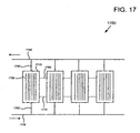
- an alternative configuration of a microchannel thermal control system 1700 includes more than one of substrates 1710 which support microchannels 1720.
- Substrates 1710 may be integrated into or otherwise coupled to any of the electrical energy storage device or electrochemical energy generation device components as discussed.
- Microchannels 1720 may be of a parallel or any other configuration in which fluid may flow from an inlet manifold 1730 to an outlet manifold 1740. Such flow may proceed through any of the more than one sets of microchannels through microchannel inlets 1750 and through microchannel outlets 1760.
- each of the sets of microchannels may include one or more interconnections 1770 and 1780 between the sets of microchannels. Providing such a structure has many advantages including, but not limited to performance characteristics, manufacturing characteristics, and application characteristics, as desired.
- electrical energy storage device or electrochemical energy generation device 110 is an electrical energy storage device that has a housing 112.
- the housing may have an external and internal surface, the internal surface being depicted as surface 114.
- Many components reside within the housing including, in some instances, the anode 122 and the cathode 120. Further, other chemicals or materials may also reside within the housing including an electrolyte 124, or other materials or chemicals as needed to generate electricity or to store energy.
- a plurality of microchannels is coupled to at least one of the internal surface 114 of the housing or at least one of the internal components such as, but not limited to cathode 120 and anode 122.
- a thermal sink 138 is coupled to the microchannels fluid connection 136.
- microchannels may be formed in a portion of a wall of the housing 114. Also, microchannels may be formed in a portion of any of the components residing within housing 112. In another exemplary embodiment, microchannels may be formed in a portion of a catalyst which may be disposed within housing 112. Further still, microchannels may be formed in electrical contacts, a current carrying conductor, a dielectric, etc. Also, microchannels may be formed integrally to any of these components or housings, or may be overlaid or disposed on or coupled to any of these components or housings. It may be advantageous to couple the microchannels to areas or components where the most heat is generated or collects.
- the fluid flowing through microchannels 132 may include any of a variety of fluids.
- Such fluids may include air, gas, water, antifreeze, molten salt, molten metal, micro-particles, liquid droplets, solid particles, etc. (see e.g. US 2006/0231233 ).
- the fluid may be at least partially circulated by any of a variety of devices including, a pump, a mechanical pump, electromagnetic (MHD) pump, electroosmotic pump, etc.
- the fluid may be circulated in any of a variety of ways including, by convection, by electroosmosis, etc.
- the electrical energy storage device may include one or more electrochemical cells, capacitive storage devices, inductive storage devices, electrolytic capacitors, supercapacitors, hypercapacitors, polyvinylidene fluoride (PVDF) based capacitors, and various batteries, including, but not limited to lithium based batteries, lithium batteries, lithium ion batteries, lithium ion nanophosphate batteries, lithium sulfur batteries, lithium ion polymer batteries, etc.
- electrochemical cells capacitive storage devices, inductive storage devices, electrolytic capacitors, supercapacitors, hypercapacitors, polyvinylidene fluoride (PVDF) based capacitors
- various batteries including, but not limited to lithium based batteries, lithium batteries, lithium ion batteries, lithium ion nanophosphate batteries, lithium sulfur batteries, lithium ion polymer batteries, etc.
- electrical energy storage device or electrochemical energy generation device 110 is a fuel cell.
- the fuel cell may include a housing having an external surface and an internal surface 114. At least one component resides within the housing. At least one component is configured to generate electrical power in combination with at least one other components, chemicals, or materials residing within the housing. In one embodiment, such components may include, but are not limited to cathode 120 and anode 122.
- a plurality of microchannels 132 may be coupled to the least one of the internal surface of the housing or the at least one internal components.
- a thermal sink 138 is coupled to the microchannels. Thermal sink 138 is configured to transfer heat to or from fluid flowing through the microchannels.
- the microchannels are formed in a portion of a wall of the housing or at least one component residing within the housing. Similar to the electrical energy storage device configuration, many of the same components may reside within the housing and may include microchannels. Further, any other components which may be unique to a fuel cell, compared to the electrical energy storage device depicted in FIG. 1 , may also include microchannels to cool such components.
- Process 300 includes providing an electrical energy storage device or an electrochemical energy generation device with a housing (process 310).
- Process 300 also includes coupling an electrical energy storage device or electrochemical energy generation device components within the housing (process 320).
- Microchannels are formed in a surface of the electrical energy storage device or the electrochemical energy generation device components (process 330).
- a fluid is then flowed through the microchannels to provide thermal control to the components and to the overall electrical energy storage device or electrochemical energy generation device (process 340).
- Process 400 includes coupling a load to draw current from the electrical energy storage device or the electrochemical energy generation device (process 410).
- the electrical energy storage device or the electrochemical energy generation device has a housing with an external surface and an internal surface.
- Process 400 also includes generating electricity by the electrical energy storage device or the electrochemical energy generation device using at least one component within the housing. The least one component is configured to generate electrical energy in combination with other components, chemicals, or materials residing within the housing (process 420).
- the electrical energy storage device is then cooled by transferring heat to fluid flowing through the microchannels coupled to at least one of the internal surface of the housing or at least one of the components (process 430). Heat is then rejected from the thermal sink that is coupled to the microchannels.
- the thermal sink is configured to transfer heat energy from the microchannels and is configured to receive a fluid flowing through the microchannels (process 440).
- a process of providing power for an electrical energy storage device or an electrochemical energy generation device includes providing an electrical energy storage device or an electrochemical energy generation device having a housing and including internal components within the housing. The process also includes providing a microchannel fluid thermal control system integrated into at least one of the interior of the housing or the internal components. Further, the process includes configuring the electrical energy storage device or electrochemical energy generation device for a platform for at least partially discharging the electrical energy storage device or the electrochemical energy generation device and using electrical energy from the electrical energy storage device.
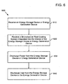
- a process of providing power from an electrical energy storage device or an electrochemical energy generation device includes receiving the electrical energy storage device or the electrochemical energy generation device housing and including internal components within the housing. The process also includes receiving a microchannel fluid thermal control system integrated into at least one of the interior of the housing or the internal components. Further, the process includes discharging power at least partially from the electrical energy storage device or the electrochemical energy generation device.
- the electrical energy storage device or the electrochemical energy generation device is configured for a platform for discharging the electrical energy storage device or the electrochemical energy generation device and using the electrical energy from the electrical energy storage device.
- Another exemplary process includes charging an electrical energy storage device.
- the electrical energy storage device is configured to receive electrical current to charge the electrical energy storage device.
- the electrical energy storage device includes a housing having an external surface and an internal surface.
- the process for charging the electrical energy storage device also may include configuring at least one component within the housing. The least one component being configured to generate electrical energy during a discharge phase in combination with other complements, chemicals, or materials residing within the housing. At least one component is configured to receive electrical charge during a charge phase.
- the exemplary process also includes providing a plurality of microchannels coupled to a least one out of the internal surface of the housing or the least one internal components to receive a heat generated during the charge phase and providing a fluid within the microchannels.
- a thermal sink is also provided to collect heat from the fluid coupled to the microchannels. The Thermal sink is configured to transfer heat energy to or from the fluid flowing through the microchannels and the thermal sink.
- a method of charging a electrical energy storage device also includes placing the electrical energy storage device to draw current from a charging source.
- the electrical energy storage device includes a housing having an external surface and an internal surface.
- the process includes receiving electricity by at least one component within the housing. At least one component is configured to receive electrical energy in combination with other components chemicals, or materials residing within the housing.
- the process also includes thermal control of the electrical energy storage device by transferring heat to a plurality of microchannels coupled to a least one of the internal surface of the housing or the at least one internal components. Further, the process includes transferring collected heat through the thermal sink coupled to the microchannels.
- the thermal sink is configured to transfer heat energy to or from the microchannels and receive a fluid through the microchannels in the thermal sink.
- a method of charging an electrical energy storage device includes receiving the electrical energy storage device including a housing and including internal components within the housing. The process also includes integrating a microchannel fluid thermal control system into at least one of the interior housing or the internal components. Further, the method includes receiving current by the electrical energy storage device, from a charging source.
- Process 500 includes providing an electrical energy storage device (process 510).
- Process 500 also includes integrating a microchannel fluid thermal control system into the interior of the electrical energy storage device (process 520).
- Process 500 further includes configuring the electrical energy storage device for discharging electricity (process 530).
- process 600 includes receiving an electrical energy storage device or an electrochemical energy generation device (process 610).
- Process 600 also includes receiving a microchannel fluid thermal control system that is integrated into the interior of the electrical energy storage device or the electrochemical energy generation device (process 620).
- process 600 includes discharging power from the electrical energy storage device or the electrochemical energy generation device to a load using the stored or generated electrical energy (process 630). Using the microchannel thermal control system heat is then discharged from the electrical energy storage device or electrochemical energy generation device (process 640).
- Process 700 includes configuring an electrical energy storage device to receive electrical charge current (process 710).
- the charge current is used to charge the electrical energy storage device, the electrical energy storage device capable of receiving a high power density current thereby causing heating of the electrical energy storage device and components of the electrical energy storage device.
- Process 700 also includes configuring interior components of the electrical energy storage device to generate electricity (process 720).
- process 700 includes providing a plurality of microchannels into the interior of a housing of the electrical energy storage device (process 730).
- the interior of the housing may include interior surfaces of the housing as well as components within the housing.
- process 700 includes providing a radiative structure or a thermal sink that is used to collect heat from the fluids flowing through the microchannels (process 740).
- Process 800 includes placing the electrical energy storage device in a situation to draw current from a charging source (process 810).
- Process 800 also includes receiving electricity by at least one component of the electrical energy storage device (process 820). Because heat is generated within the electrical energy storage device during the charging process, process 800 also includes thermal control of the electrical energy storage device by transferring heat to microchannels which are configured within housing of the electrical energy storage device (process 830). Heat is then rejected via a radiator or other thermal sink structure from the microchannels by transferring heat from the microchannel to the fluid flowing through the microchannels and to the thermal sink (process 840).
- Process 900 includes receiving an electrical energy storage device in a situation whereby the electrical energy storage device may be charged (process 910).
- Process 900 also includes receiving a microchannel fluid thermal control system is integrated into the electrical energy storage device (process 920).
- a microchannel fluid thermal control system may be one that is applied directly to components within the housing of the electrical energy storage device or may be one that is integrated into the housing of the electrical energy storage device or components within the housing of the electrical energy storage device.
- Process 900 also includes receiving current by the electrical energy storage device from the charging source (process 930).
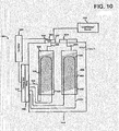
- Electrical energy storage device or electrochemical energy generation device 1000 may include a housing 1010 having an outer surface 1012 and an inner surface 1014. Within housing 1010 may be a plurality of components, chemicals, materials, etc.
- a cathode 1020 may be coupled to a positive terminal 1027 by a conductive connection 1026.
- Cathode 1020 may have a surface 1022. Surface 1022 may be overlaid with or be integrated into cathode 1020 a high thermal conductivity material 1023 that is in thermal communication with the fluid circuit 1036.
- High thermal conductivity material 1023 may have a high k-value.
- the high k-value may be greater than approximately 410 W/(m*K).
- Fluid circuit 1036 may be used to circulate fluid to conduct heat away from cathode 1020 via the high thermal conductivity of the material 1023. In electrical energy storage devices and electrochemical energy generation devices that are charged or discharged rapidly or that manage a high power density, efficient thermal control is needed to maintain desired temperature. The use of high thermal conductivity materials as applied, allows efficient rejection of heat to maintain desired temperatures.
- Thermal circuit 1036 is coupled to a thermal sink 1038 and optionally through a pump, 1040. Pump 1040 helps move fluid through circuit 1036.
- an anode 1030 may reside within housing 1010 having a high thermal conductivity material 1033 coupled to or integrated into surface 1032.
- a fluid circuit 1034 is in thermal communication with material 1033. Fluid circuit 1034 is coupled to thermal sink 1038 optionally through a pump 1040. Anode 1030 is electrically coupled to a negative terminal 1029 through conductive connection 1028. Positive terminal 1027 and negative terminal 1029 may be coupled to a load or charge source 1070.
- a controller 1060 may be coupled to any of a variety of mechanisms within system 1000 including, but not limited to, pump 1040 for controlling the rate of fluid flow within circuits 1036 and 1038, for example. Controller 1060 may be coupled to any of a variety of sensors including, but not limited to a current sensor 1062 which may be in a variety of locations including, but not limited to at terminal 1027.
- sensors may also be used including, but not limited to temperature sensors, voltage sensors, flow sensors, chemical concentration sensors, and the like.
- the use of high thermal conductivity materials to aid the rejection of heat within the interior of an electrical energy storage device or an electrochemical energy generation device may be beneficial to provide adequate thermal control of such devices during rapid charging or rapid discharging, etc.
- the electrical energy storage device or the electrochemical energy generation device includes high thermal conductivity materials which include but are not limited to diamond and diamond based materials, diamond films, diamond composites (such as diamond-loaded copper or diamond-loaded aluminum), carbon fibers (including graphite fiber composites, as may exist in combination with materials in a matrix such as aluminum, Silicon Carbide (SiC), or various polymers), carbon-carbon materials (such as carbon fibers in a carbon matrix), carbon nanotubes, carbon aerogels and the like.
- the high thermal conductivity materials may be formed into micro heat pipes, and other structures which will be beneficial to increase thermal conductivity.
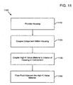
- the method includes providing a housing which may have an external surface and an internal surface (process 1110).
- the method also includes coupling at least one component within the housing. At least one component is configured to generate electrical power in combination with other components, chemicals, or materials which may be residing within the housing (process 1120).
- the method includes forming a plurality of thermal control structures of a high thermal conductivity material which is coupled to at least one of the internal surface of the housing or the least one internal components.
- the high thermal conductive material may have a high k-value, the high k-value being greater than approximately 410 W/(m*K) (process 1130).
- the method includes flowing a fluid adjacent the high thermal conductivity material to remove heat from the high thermal conductivity material (process 1140).
- the thermal sink may be formed at least partially of a high thermal conductivity material as described above.
- a structure may be used in a method of thermal control of an electrical energy storage device or an electrochemical energy generation device.
- a method of thermal control may include providing a housing having an external surface and an internal surface.
- the method may also include coupling at least one component within the housing, at least one component being configured to generate electrical power in combination with other components, chemicals, or materials residing within the housing.
- the method of thermal control may include forming a plurality of thermal control structures coupled to at least one of the internal surface of the housing or the at least one internal components.
- the method further includes flowing a fluid adjacent a plurality of thermal control structures and transferring heat to or from a thermal sink.
- the thermal sink is formed at least partially of a high thermal conductive material having a high k-value.
- the high k-value may be greater than approximately 410 W/(m*K).
- Process 1200 may include placing an electrical load to draw current from the electrical energy storage device or the electrochemical energy generation device (process 1210).
- Process 1200 may also include thermal control of the electrical energy storage device or electrochemical energy generation device by transferring heat to thermal control structures which are formed of a high k-value material (process 1220). Further, process 1200 includes flowing fluid adjacent the high k-value material to remove heat therefrom (process 1230).
- a method 1300 for providing power from an electrical energy storage device or an electrochemical energy generation device includes providing the electrical energy storage device or the electrochemical energy generation device.
- the electrical energy storage device or the electrochemical energy generation device includes a housing and includes internal components within the housing (process 1310).
- Process 1300 also includes thermal control of the electrical energy storage device or the electrochemical energy generation device by transferring heat to thermal control structures which are formed of high k-value material (process 1320). Further, process 1300 includes flowing fluid adjacent the high k-value material (process 1330). Further still, process 1300 includes configuring the electrical energy storage device or the electrochemical energy generation device for a platform for discharging the electrical energy storage device or the electrochemical energy generation device (process 1340).
- a method 1400 of providing power from an electrical energy storage device or an electrochemical energy generation device includes providing the electrical energy storage device or the electrochemical energy generation device with a housing and with internal components within the housing (process 1410). The method also includes thermal control of the electrical energy storage device or the electrochemical energy generation device by transferring heat to a plurality of thermal control of structures formed of high k-value material (process 1420). Further, the method includes flowing fluid adjacent the high k-value materials (process 1430). Further still, process 1400 includes configuring the electrical energy storage device or the electrochemical energy generation device for a platform for discharging the electrical energy storage device or the electrochemical energy generation device and using the electrical energy from the electrical energy storage device or the electrochemical energy generation device (process 1400).
- a method 1500 of charging an electrical energy storage device may include configuring the electrical energy storage device to receive electrical current to charge the electrical energy storage device (process 1510).
- the electrical energy storage device may include a housing having an external surface and an internal surface.
- the method may also include configuring at least one component within the housing.
- the least one component is configured to generate electrical energy, during a discharge phase, in combination with other components chemicals or materials residing within housing and at least one component configured to receive electrical charge during a charge phase (process 1520).
- a plurality of thermal control structures are provided of a high thermal conductivity material coupled to at least one of the internal surface of the housing or the least one internal components (process 1520).
- the high thermal conductivity material may have a high k-value the high k-value is greater than approximately 410 W/(m*K).
- the thermal conductivity material is configured to receive heat generated during the charge phase (process 1530).
- a thermal sink is provided to transfer heat to or from the fluid coupled to the high thermal conductivity material (process 1540).
- a thermal sink is configured to transfer heat energy to or from the fluid flowing through the high thermal conductivity material and the thermal sink.
- a method 1600 of charging an electrical energy storage device includes placing the electrical energy storage device in a situation to draw charge current (process 1600).
- Process 1600 also includes thermal control of the electrical energy storage device by transferring heat to a plurality of thermal control structures formed of high thermal conductivity material and flowing fluid thereby (process 1620).
- Process 1600 also includes rejecting heat from the fluid through a radiative structure or a thermal sink (process 1630).
- structures, systems, and processes described above may also be applied to structures, systems, and processes which use microchannel thermal control for thermal control of electrical energy storage devices or electrochemical energy generation devices and base such thermal control on current (or other states of the electrical energy storage device or electrochemical energy generation device, such as (but not limited to voltage, power, temperature, charge state, etc.) that is either delivered to or from the electrical energy storage device or the electrochemical energy generation device.
- the current may be sensed by a variety of sensors and controlled by a pump that controls the rate of fluid flow using any of a variety of control algorithms and controllers.
- control algorithms may include but are not limited to classical control, feedback control, nonlinear control, adaptive control, etc.
- the control algorithms may also include state estimator's, adaptive control algorithms, Kalman filters, models of the electrical energy storage device or the electrochemical energy generation device.
- the pump may be controlled is any of a variety of ways including increased flow as current draw increase, flow may be increased linearly as current draw increase, flow may be decreased as current draw decreased, flow may be decreased nonlinearly as current draw decreases, flow may be increased linearly as current draw increases, flow may be decreased nonlinearly as current draw decreases, or flow may be increased nonlinearly as current draw increases and flow may be decreased linearly as current draw decreases. Further, other possibilities are equally applicable depending on the design specifications and desired responses.
- structures, systems, and processes described above may also be applied to structures, systems, and processes which use high thermal conductivity materials and for thermal control of electrical energy storage devices or electrochemical energy generation devices and base such thermal control on a state or states of a mobile device which the electrical energy storage device or electrochemical energy generation device is powering.
- the current may be sensed by a variety of sensors or by software which determines the state of the mobile device and a pump is controlled that controls the rate of fluid flow using any of a variety of control algorithms and controllers.
- control algorithms may include but are not limited to classical control, feedback control, nonlinear control, adaptive control, etc.
- the control algorithms may also include state estimator's, adaptive control algorithms, Kalman filters, models of the electrical energy storage device or the electrochemical energy generation device, etc.
- the mobile device states on which fluid flow may be based may include any of a variety of states including but not limited to brightness, processing speed, processing demands, processor tasks, display brightness, hard disk state, hard disk speed, hard disk usage, wireless communication state, etc.
- Such a mobile device may include any of a variety of mobile electronic devices including, but not limited to, a computer, a laptop computer, a mobile phone, a global positioning system (GPS) unit, a power tool, etc. Further, other possibilities are equally applicable depending on the performance characteristics desired.
- GPS global positioning system
- the mobile device may be a laptop computer having a battery pack that is cooled by a microchannel thermal control system.
- the microchannel thermal control system may include a pump or other device that controls the rate of fluid flow through the microchannels and thus the rate of thermal control. Because current demands may cause heating of the battery pack due to increased processing speed, increased processing tasks, increased hard disk speed, increased hard disk usage, etc. As discussed above, the demands for thermal control therefore increase.
- the control system is configured to detect or determine the state of the mobile device and make adjustments to the rate of thermal control by altering the rate of flow through the microchannel system thermal control based on mobile device states may be applied in the context of microchannel-based thermal control, high thermal conductivity material-based thermal control systems, and further microchannel and high thermal conductivity material thermal control systems.
- control of fluid flow is based on mobile device states
- a thermal control system which uses microchannels.
- the system may be applied to an electrochemical energy generation device or electrical energy storage device that uses thermal and high thermal conduct to the materials in conjunction with a fluid thermal control system.
- the control system described in which thermal control is based on mobile device states may also be applied to a system which uses a combination of microchannel thermal control and high thermal conductivity to the materials.
- the fluid thermal control system described above may be applied to electrical energy storage devices and energy to generation devices that are used in vehicle systems.
- a fluid pump may be coupled to a microchannel thermal control system of the electrical energy storage device or the electrochemical energy generation device.
- the electrical energy storage device or the electrochemical energy generation device may be configured to provide electrical energy to the drivetrain of the vehicle or in powering other equipment in the vehicle.
- a processor is configured to determine at least one of the states of the vehicle.
- a vehicle sensor may be coupled to the processor and may be configured to sense at least one vehicle characteristic.
- a controller is used with a control algorithm and maybe configured to control the functioning of the pump as a function of at least one vehicle state.
- the vehicle states may include but are not limited to engine speed, engine torque, engine acceleration, engine temperature, terrain grade, vehicle acceleration, vehicle speed, etc.
- the concept and control system may be applied to any of a variety of vehicles including, but not limited to, a computer integrated into a vehicle, a truck, a boat, a bus, train, an automobile, etc.
- a variety of sensors may be used including but not limited to current sensors, voltage sensors, temperature sensors, speed sensors, accelerometers, orientation sensors, attitude sensors, etc.
- the methods of applying thermal control based on vehicle states may be applied in the context of microchannel-based thermal control, high thermal conductivity material-based thermal control systems, and further microchannel and high thermal conductivity material thermal control systems.
- an electrical energy storage device or electrochemical energy generation device in another exemplary embodiment, includes a housing having an external surface and an internal surface. Components may reside within the housing. The components are configured to generate electrical energy in combination with at least one of other components, chemicals, or materials residing within the housing.
- a plurality of microchannels may be fashioned to at least one of the internal surface of the housing or the at least one internal components. The plurality of microchannels may be divided into at least two sets of microchannels although any number of sets may be used. The two sets, for example, may be separated by at least one valve.
- a controller is configured to provide control signals to the valve. The valve may be configured to control fluid flow in at least two sets of microchannel such that fluid could flow through either set of microchannels or both sets simultaneously.
- the control signals are based on thermal control demand.
- the thermal control demand may be of the overall system, or the thermal control demand may be localized.
- a thermal sink is coupled to the microchannels. The thermal sink is configured to transfer heat energy to or from the microchannel surfaces via the fluid flowing through the microchannel and the sinks.
- the thermal control demands may be met by controlling the action of opening or closing of the valves such that fluid may selectively flow through various sets of microchannel to provide needed localized thermal control.
- a signal bearing medium examples include, but are not limited to, the following: a recordable type medium such as a floppy disk, a hard disk drive, a Compact Disc (CD), a Digital Video Disk (DVD), a digital tape, a computer memory, etc.; and a transmission type medium such as a digital and/or an analog communication medium (e.g., a fiber optic cable, a waveguide, a wired communications link, a wireless communication link, etc.).
- a recordable type medium such as a floppy disk, a hard disk drive, a Compact Disc (CD), a Digital Video Disk (DVD), a digital tape, a computer memory, etc.
- CD Compact Disc
- DVD Digital Video Disk
- electro-mechanical system includes, but is not limited to, electrical circuitry operably coupled with a transducer (e.g., an actuator, a motor, a piezoelectric crystal, etc.), electrical circuitry having at least one discrete electrical circuit, electrical circuitry having at least one integrated circuit, electrical circuitry having at least one application specific integrated circuit, electrical circuitry forming a general purpose computing device configured by a computer program (e.g., a general purpose computer configured by a computer program which at least partially carries out processes and/or devices described herein, or a microprocessor configured by a computer program which at least partially carries out processes and/or devices described herein), electrical circuitry forming a memory device (e.g., forms of random access memory), electrical circuitry forming a communications device (e.g., a modem, communications switch, or optical-electrical equipment), and any non-electrical analog thereto, such as optical or other analogs.
- a transducer e.g., an actuator, a motor, a piezo
- electro-mechanical systems include but are not limited to a variety of consumer electronics systems, as well as other systems such as motorized transport systems, factory automation systems, security systems, and communication/computing systems.
- electro-mechanical as used herein is not necessarily limited to a system that has both electrical and mechanical actuation except as context may dictate otherwise.
- electrical circuitry includes, but is not limited to, electrical circuitry having at least one discrete electrical circuit, electrical circuitry having at least one integrated circuit, electrical circuitry having at least one application specific integrated circuit, electrical circuitry forming a general purpose computing device configured by a computer program (e.g., a general purpose computer configured by a computer program which at least partially carries out processes and/or devices described herein, or a microprocessor configured by a computer program which at least partially carries out processes and/or devices described herein), electrical circuitry forming a memory device (e.g., forms of random access memory), and/or electrical circuitry forming a communications device (e.g., a modem, communications switch, or optical-electrical equipment).
- a computer program e.g., a general purpose computer configured by a computer program which at least partially carries out processes and/or devices described herein, or a microprocessor configured by a computer program which at least partially carries out processes and/or devices described herein
- electrical circuitry forming a memory device
- examples of such other devices and/or processes and/or systems might include - as appropriate to context and application-all or part of devices and/or processes and/or systems of (a) an air conveyance (e.g., an airplane, rocket, hovercraft, helicopter, etc.), (b) a ground conveyance (e.g., a car, truck, locomotive, tank, armored personnel carrier, etc.), (c) a building (e.g., a home, warehouse, office, etc.), (d) an appliance (e.g., a refrigerator, a washing machine, a dryer, etc.), (e) a communications system (e.g., a networked system, a telephone system, a Voice over IP system, etc.), (f) a business entity (e.g., an Internet Service Provider (ISP) entity such as Comcast Cable, Quest, Southwestern Bell, etc), or (g) a wired/wireless services entity such as Sprint, Cingular, Nextel,
- ISP Internet Service Provider
- any two components so associated can also be viewed as being “operably connected”, or “operably coupled”, to each other to achieve the desired functionality, and any two components capable of being so associated can also be viewed as being “operably couplable”, to each other to achieve the desired functionality.
- operably couplable include but are not limited to physically mateable and/or physically interacting components and/or wirelessly interactable and/or wirelessly interacting components and/or logically interacting and/or logically interactable components.
Description
- The description herein generally relates to the field of microchannel thermal control systems for electrical energy storage devices or electrochemical energy generation devices. Microchannel cooling has been conventionally applied to devices such as integrated circuit devices and laser diodes. However, microchannel cooling has been limited application in cooling of electrical energy storage devices or electrochemical energy generation devices.
- Conventionally, there is a need for advantageous structures and methods for thermal control of electrical energy storage devices or electrochemical energy generation devices by the use of microchannels and the like in a variety of structures and in a variety of usage.
-
US 2007/184320 discloses a cooling device for a PEM-type fuel cell, which comprises a finned radiator of a specific type, in which the water circulates in a laminar flow (seeUS 2007/184320 , paragraph [0033]). In paragraph [0145],US 2007/184320 dsicloses that such a cell comprises a stack of cells which are each formed by a proton-conducting polymer membrane (in particular that sold under the trade mark Nafion(R) by Dupont de Nemours) and an oxidation catalyst film (platinum), sandwiched between two permeable electrodes. Between two electrodes of opposite signs belonging to two neighbouring cells, a bipolar plate is arranged, with high electrical and thermal conductivities and provided with grooved faces. These grooves constitute ducts intended to ensure the hydrogen supply to the anode of the membrane of a given cell, the air supply to the cathode of the membrane of an adjacent cell and the evacuation of the water vapor produced. In certain embodiments of these bipolar plates, their center section is passed over by numerous parallel mini-channels, which the cooling water of the cell is intended to run through. For this purpose, they are often made of a highly conductive material which is easy to machine, for example graphite. The membrane operates at a maximum temperature comprised between 80 and 85° C., with an maximum average yield of approximately 50%. This again creates the need for an acceptable efficient cooling device. Each cell generates a voltage of approximately 0.8 volts and an electrical power of at most 0.4 W/cm2, i.e. with a surface area of 25 dm2, a power of the order of a kilowatt. Under these conditions, the density of heat flow to be evacuated by the heat dissipation zone of each bipolar plate is approximately 0.4 W/cm2, which is very low.JP H09 50821 A - The presently claimed subject matter is defined in the claims.
- In one aspect, an electrical energy strorage device or an electrochemical energy generation device, comprises: a housing having an external surface and an internal surface; at least one component within the housing, at least one component being configured to generate electrical power in combination with at least one of other components, chemicals, or materials residing within the housing, wherein at least one component within the housing is either a cathode and an anode; a plurality of microchannels integrated into the at least one component,wherein the mircochannels are a sealed fluid conduit; a thermal sink coupled to the microchannels, the thermal sink being configured to transfer heat to or from fluid flowing through the microchannels, wherein the fluid is at least partially circulated by means of a pump; a controller coupled to the pump and configured to control the pump.
- In one aspect, a method of operating the electrochemical energy storage device or the electrochemical energy generation device, comprises: placing an electrical load to draw current from the device; generating electricity by the at least one component within the housing; altering the temperature of the device by transferring heat to the plurality of microchannels integrated into the at least one component, wherein the at least one internal component is one of a cathode and an anode; and rejecting the collected heat through a thermal sink coupled to the microchannels, the thermal sink being configured to transfer heat energy from a fluid and to receive fluid flowing through the microchannels wherein the fluid is at least partially circulated by means of a pump controlled by a controller.
- In addition to the foregoing, other aspects are described in the claims, drawings, and text forming a part of the present disclosure.
- The foregoing is a summary and thus contains, by necessity, simplifications, generalizations and omissions of detail; consequently, those skilled in the art will appreciate that the summary is illustrative only and is NOT intended to be in any way limiting. Other aspects, features, and advantages of the devices and/or processes and/or other subject matter described herein will become apparent in the teachings set forth herein.
- The foregoing summary is illustrative only and is not intended to be in any way limiting.
Figures 1-9 and17 are embodiments of the claimed subject matter whilstFigures 10-16 are examples of other configurations. In addition to the illustrative aspects, embodiments, and features described above, further aspects, embodiments, and features will become apparent by reference to the drawings and the following detailed description, of which: -
FIG. 1 is an exemplary microchannel temperature alteration system associated with an electrical energy storage device or an electrochemical energy generation device; -
FIG. 2 is an exemplary depiction of a cross section and cutaway of a plurality of microchannels; -
FIG. 3 is an exemplary process diagram for altering temperature of an electrical energy storage device or an electrochemical energy generation device; -
FIG. 4 is an exemplary process diagram for altering temperature of an electrical energy storage device or an electrochemical energy generation device; -
FIG. 5 is an exemplary process diagram for altering temperature of an electrical energy storage device or an electrochemical energy generation device while discharging; -
FIG. 6 is an exemplary process diagram for altering temperature of an electrical energy storage device or an electrochemical energy generation device during discharging; -
FIG. 7 is an exemplary process diagram for altering temperature of an electrical energy storage device during charging; -
FIG. 8 is an exemplary process diagram for altering temperature of an electrical energy storage device during charging; -
FIG. 9 is an exemplary process diagram for altering temperature of an electrical energy storage device during charging; -
FIG. 10 is an example of a high thermal conductivity material altering temperature of device associated with an electrical energy storage device or an electrochemical energy generation device; -
FIG. 11 is an example of a process diagram for altering temperature of an electrical energy storage device or an electrochemical energy generation device using high thermal conductivity materials; -
FIG. 12 is an example of a process diagram for altering temperature of an electrical energy storage device or an electrochemical energy generation device using high thermal conductivity materials during discharge; -
FIG. 13 is an example of a process diagram of an electrical energy storage device or an electrochemical energy generation device using high thermal conductivity materials during discharging; -
FIG. 14 is an example of a process diagram for altering temperature of an electrical energy storage device for an electrochemical energy generation device during discharging; -
FIG. 15 is an example of a process diagram for an electrical energy storage device using high thermal conductivity materials during charging; and -
FIG. 16 is an example of a process diagram for altering temperature of an electrical energy storage device using high thermal conductivity materials during charging. -
FIG. 17 is an exemplary block diagram of a microchannel manifold system. - In the following detailed description, reference is made to the accompanying drawings, which form a part hereof. In the drawings, similar symbols typically identify similar components, unless context dictates otherwise. The illustrative embodiments described in the detailed description, drawings, and claims are not meant to be limiting. Other embodiments may be utilized, and other changes may be made, without departing from the scope of the subject matter presented here. Those having skill in the art will recognize that the state of the art has progressed to the point where there is little distinction left between hardware and software implementations of aspects of systems; the use of hardware or software is generally (but not always, in that in certain contexts the choice between hardware and software can become significant) a design choice representing cost vs. efficiency tradeoffs. Those having skill in the art will appreciate that there are various vehicles by which processes and/or systems and/or other technologies described herein can be effected (e.g., hardware, software, and/or firmware), and that the preferred vehicle will vary with the context in which the processes and/or systems and/or other technologies are deployed. For example, if an implementer determines that speed and accuracy are paramount, the implementer may opt for a mainly hardware and/or firmware vehicle; alternatively, if flexibility is paramount, the implementer may opt for a mainly software implementation; or, yet again alternatively, the implementer may opt for some combination of hardware, software, and/or firmware. Hence, there are several possible vehicles by which the processes and/or devices and/or other technologies described herein may be effected, none of which is inherently superior to the other in that any vehicle to be utilized is a choice dependent upon the context in which the vehicle will be deployed and the specific concerns (e.g., speed, flexibility, or predictability) of the implementer, any of which may vary. Those skilled in the art will recognize that optical aspects of implementations will typically employ optically-oriented hardware, software, and or firmware.
- Microchannels used to cool integrated circuits have been understood since the early 1980s and disclosed in research published by professors Dr. David Tuckerman and Dr. Fabian Pease. Pease published research showing that microchannels etched into silicon may provide densities as high as 1000 W per square centimeter. Such microchannel structures have been shown to be put into practical use by cooling integrated circuits, such as those described in
U.S. Patent Nos. 4,541,040 ;7,156,159 ;7,185,697 ; andU.S. Patent Application Publication No.2006/0231233 . However, practical application to thermal control of electrical energy storage devices and electrochemical energy generation devices has not been accomplished or suggested. Such microchannel structures may particularly be suited for removing heat from such devices especially in the case of ultrahigh power density batteries or other electrical storage devices, for example hyper capacitors, or electrochemical energy generation devices such as, but not limited to fuel cells. Microchannel coolers and passive high thermal conductivity materials, such as, but not limited to diamond films, micro heat pipes, microchannel plates, etc., may be used to aid in thermal control of ultra-high performance nano structured batteries, and the like, which will generate high thermal loads and high thermal power densities, particularly during rapid charging, and/or during rapid discharging. Such devices may be exemplified by the electrical energy storage device as described inU.S. Published Patent Application No. 2008/0044725 . The reference also describes some of the demands which may be fulfilled by such high power density electrical energy storage devices. - Efficiency of microstructure microchannel heat collectors and thermal sinks, may be attributed to the heat generated by the energy storage or electrochemical energy generation devices travelling a relatively small distance from the heat generation point in the electrical energy storage device, or electrochemical energy generation device, where the heat is generated and transferred through the walls of the microchannel. Also, the heat from the walls of the microchannel conducts a very small distance into the fluid before the heat energy is carried away to a thermal sink, such as a radiator, or the like. Because of the structure of the microchannels where the height of the microchannel is typically much greater than the width, it may be incorporated into various portions internally of the electrical energy storage device or the electrochemical energy generation device. For example, the microchannel thermal control structures may be incorporated into the anode, or the cathode of a battery or electrochemical energy generation device. Further, the microchannel structures may be integrated into walls of the housing of an electrical energy storage device or an electrochemical energy generation device. Further, the microchannel structures may be incorporated into other portions internally of the electrical energy storage device or electrochemical energy generation device.
- One of the advantages of using the microchannel structures is that turbulent flow within the channels is not necessary to increase heat transfer efficiency. Microchannel structures neither require nor create turbulent flow. Conventional macrochannels require turbulence to increase cooling efficiency otherwise the fluid flowing in the middle of the channel stays relatively cool. Turbulent flow within the fluid channel mixes the hot fluid next to the wall of the channel with the cooler fluid in the middle of the channel. However, such turbulence and mixing decreases the efficiency of cooling. Microchannels, instead, have the advantage that the heat transfer coefficient "h" is inversely proportional to the width of the channel. As "h" decreases efficiency increases. A very narrow channel completely heats a very thin layer of fluid as it travels through the collector.
- A compact thermal control system for electrical energy storage devices and electrochemical energy generation devices which may be used in applications such as, but not limited to mobile devices, electric vehicles, hybrid electric vehicles, etc. maybe based on micro heat exchangers having microchannel heat collectors or heat collectors at least partially formed of high thermal conductivity materals. Such microchannel heat collectors may be machined or fabricated in silicon or other metals, or other materials including high thermal conductivity materials and use active pumps systems or passive systems including, but not limited to electro osmotic pumps or other pumps, etc. A system such as this may be a hermetically closed system that may be arranged in a modular fashion in which a portion of microchannels or a portion of a high thermal conductivity material heat collector is disposed within the housing of the electrical energy storage device or the electrochemical energy generation device. Other configurations may be such that the microchannels or other heat collector are incorporated or machined directly into portions of the electrical energy storage device or electrochemical energy generation device. Such microchannel heat exchangers, and such systems as described, may be formed as extremely compact and power efficient systems such that the total system offers increased performance characteristics heat pipes, vapor chambers, and other heat transfer devices which are conventionally used for removing heat from similar types of electrical energy storage devices and electrochemical energy generation devices.
- Referring now to
FIG. 1 , athermal control system 100 for an electrical energy storage device or an electrochemical energy generation device 110 is depicted. Electrical energy storage device or electrochemical energy generation device 110 may include, but is not limited to any of a variety of batteries or electrochemical cells such as, but not limited to lithium based batteries, lithium ion batteries, lithium ion nano phosphate batteries, lithium sulfur batteries, lithium ion polymer batteries, sodium sulfur batteries, etc. In fact, such thermal control technology could be applied to any typical type of electro-chemical cell in existence today or to be developed. Further, other types of electrical energy storage devices may be used in place of battery 110 such as, capacitor devices including, but not limited to capacitive storage devices, inductive storage devices, electrolytic capacitors, hyper capacitors (as described inU.S. Published Patent Application No. 2004/0071944 andU.S. Patent No. 7428137 ), polyvinylidene fluoride (PVDF) based capacitors carbon nanotube based capacitors, other conductive polymer based capacitors, carbon aerogel based capacitors, etc. Further still, energy storage or electrochemical energy generation device 110 may be representative of a fuel cell (as described inU.S. Published Patent Application No. 2009/0068521 ), or other electrochemical energy generation devices which may be known, or developed. - Electrical energy storage device or electrochemical energy generation device 110 includes a housing having a housing wall with an
interior wall surface 114 andexterior wall surface 112.Interior wall surface 114 of the housing may be filled with anelectrolyte 124 or other material depending on the structure of either the electrical energy storage device or the electrochemical energy generation device 110. Electrical energy storage device or electrochemical energy generation device 110 may include, acathode 120 coupled to apositive terminal 127 by aconductor 126. In an exemplary embodiment, load 120 may include a number ofmicrochannel structures 132.Microchannel structures 132 are integrated intocathode 120 such that heat emanating fromcathode 120 may be collected by themicrochannel structures 132. Suchmicrochannel structures 132 may be formed by any of a variety of methods including etching, micromachining, and the like. Various materials for formingcathode 120 may be used, as is well known in the art depending on the type of electrical energy storage device or electrochemical energy generation device 110. Afluid connection 136 is coupled tomicrochannels 132.Fluid connections 136 are coupled to athermal sink 138 through apump 140. Such athermal sink 138 may be a radiator or other form of heatsink. Apump 140 may also be coupled to afluid circuit 136 in order to move fluid throughmicrochannels 132. In one embodiment, a pump is used. In alternative embodiments, the fluid may be moved by osmotic pressure or the like without use of apump 140. Similar tocathode 120, ananode 122 is electrically coupled to anegative terminal 129 of electrical energy storage device or electrochemical energy generation device 110 by a conductor 128. Similar tocathode 120,anode 122 includes amicrochannel structure 130 integrated intoanode 122.Microchannel structure 130 is fluidly coupled, by afluid connection 134, tothermal sink 138 in much the same way thatfluid connection 136 is coupled tothermal sink 138. - In an exemplary embodiment, a load or a
charge source 120 is electrically coupled topositive terminal 127 andnegative terminal 129 of electrical energy storage device or electrochemical energy generation device 110.Load 120 may be any of a variety of possible devices using energy from electrical energy storage device or electrochemical energy generation device 110. Chargesource 120 may be any type of charging device that is used to charge electrical energy storage device 110. During charging, or during discharging by use of a load, large amounts of heat may be generated within electrical energy storage device or electrochemical energy generation device 110. Accordingly, it may be advantageous to use a microchannel thermal control system as described. In one exemplary embodiment, acontroller 160 may be coupled to pump 140.Controller 160 may be any of a variety of controllers control devices, etc. for controlling the speed ofpump 140. For example, pump 140 may be coupled to asensor 162 which detects characteristics of electrical energy storage device or electrochemical energy generation device 110.Sensor 162 may be located at any of a variety of locations associated with electrical energy storage device or electrochemical energy generation device 110. Alternatively,controller 160 may be coupled to load orcharge source 120 to detect characteristics of the usage of load orcharge source 120.Controller 160 may be used to controlpump 140 based on a variety of factors including, but not limited to a current draw, a current discharge, voltage, various states of the device using energy from electrical energy storage device or electrochemical energy generation device 110, or variable various states of a vehicle using electrical energy storage device or electrochemical energy generation device 110, or further states of thecharge source 120. - In accordance with an exemplary embodiment, it may be desirable to cool the electrical energy storage device or the electrochemical energy generation device in anticipation of a heat generating event, such as discharge or energy demand or charging. By cooling in advance of the heat generating event, the thermal control system may be better enabled to keep up with the cooling demands. It is in a sense a "head start" for the cooling system. In an exemplary embodiment the "head start" may be determined by a processor which may be enabled with programming to monitor systems and make determinations as to when energy may be demanded or charging may occur. In other exemplary embodiments, the "head start" may be done in accordance with a schedule or in accordance with other preset or predetermined times.
- Referring now to
FIG. 2 , a perspective cross-section of anexemplary cathode 120 is depicted. The cross section ofFIG. 2 depictsmicrochannels 132 built into or integrated intocathode 120.Microchannels 132 are sealed fluid conduits having atop portion 133 shown partially cut-away.Microchannels 132 are not shown in a scaled depiction because microchannels 132 conventionally are of extremely small width, on the order of, but not limited to the width of a human hair. The height ofmicrochannels 132 may be much greater than the width to achieve efficient laminar flow thermal control. The high aspect ratio of the microchannels increases the total surface area of the microchannel structures touching the fluid flow. The width of themicrochannels 132 may be on the order of 10 µm, but is not limited thereto.FIG. 2 depicts a single configuration ofmicrochannels 132 in which the microchannels are arranged side-by-side and fluid may flow through all the microchannels in parallel or may flow in a serial manner back and forth (serpentine) through each of the microchannels to complete a fluid circuit. Many other configurations of microchannels may also be conceived without departing from the scope of the disclosure and of the invention as claimed herein. - Referring now to
FIG 17 , an alternative configuration of a microchannelthermal control system 1700 includes more than one ofsubstrates 1710 whichsupport microchannels 1720.Substrates 1710 may be integrated into or otherwise coupled to any of the electrical energy storage device or electrochemical energy generation device components as discussed.Microchannels 1720 may be of a parallel or any other configuration in which fluid may flow from aninlet manifold 1730 to anoutlet manifold 1740. Such flow may proceed through any of the more than one sets of microchannels throughmicrochannel inlets 1750 and throughmicrochannel outlets 1760. In yet another configuration each of the sets of microchannels may include one ormore interconnections - In one exemplary embodiment, electrical energy storage device or electrochemical energy generation device 110 is an electrical energy storage device that has a
housing 112. The housing may have an external and internal surface, the internal surface being depicted assurface 114. Many components reside within the housing including, in some instances, theanode 122 and thecathode 120. Further, other chemicals or materials may also reside within the housing including anelectrolyte 124, or other materials or chemicals as needed to generate electricity or to store energy. In one exemplary embodiment a plurality of microchannels is coupled to at least one of theinternal surface 114 of the housing or at least one of the internal components such as, but not limited tocathode 120 andanode 122. Athermal sink 138 is coupled to themicrochannels fluid connection 136. Thethermal sink 138 is configured to transfer heat to or from fluid flowing throughmicrochannels 132. In one exemplary embodiment, microchannels may be formed in a portion of a wall of thehousing 114. Also, microchannels may be formed in a portion of any of the components residing withinhousing 112. In another exemplary embodiment, microchannels may be formed in a portion of a catalyst which may be disposed withinhousing 112. Further still, microchannels may be formed in electrical contacts, a current carrying conductor, a dielectric, etc. Also, microchannels may be formed integrally to any of these components or housings, or may be overlaid or disposed on or coupled to any of these components or housings. It may be advantageous to couple the microchannels to areas or components where the most heat is generated or collects. - In an exemplary embodiment, the fluid flowing through
microchannels 132 may include any of a variety of fluids. Such fluids may include air, gas, water, antifreeze, molten salt, molten metal, micro-particles, liquid droplets, solid particles, etc. (see e.g.US 2006/0231233 ). Also, in an exemplary embodiment, the fluid may be at least partially circulated by any of a variety of devices including, a pump, a mechanical pump, electromagnetic (MHD) pump, electroosmotic pump, etc. The fluid may be circulated in any of a variety of ways including, by convection, by electroosmosis, etc. Further, in accordance with an exemplary embodiment, the electrical energy storage device may include one or more electrochemical cells, capacitive storage devices, inductive storage devices, electrolytic capacitors, supercapacitors, hypercapacitors, polyvinylidene fluoride (PVDF) based capacitors, and various batteries, including, but not limited to lithium based batteries, lithium batteries, lithium ion batteries, lithium ion nanophosphate batteries, lithium sulfur batteries, lithium ion polymer batteries, etc. - In accordance with another exemplary embodiment, electrical energy storage device or electrochemical energy generation device 110 is a fuel cell. The fuel cell may include a housing having an external surface and an
internal surface 114. At least one component resides within the housing. At least one component is configured to generate electrical power in combination with at least one other components, chemicals, or materials residing within the housing. In one embodiment, such components may include, but are not limited tocathode 120 andanode 122. A plurality ofmicrochannels 132 may be coupled to the least one of the internal surface of the housing or the at least one internal components. Athermal sink 138, is coupled to the microchannels.Thermal sink 138 is configured to transfer heat to or from fluid flowing through the microchannels. In one exemplary embodiment, the microchannels are formed in a portion of a wall of the housing or at least one component residing within the housing. Similar to the electrical energy storage device configuration, many of the same components may reside within the housing and may include microchannels. Further, any other components which may be unique to a fuel cell, compared to the electrical energy storage device depicted inFIG. 1 , may also include microchannels to cool such components. - Referring now to
FIG. 3 , aprocess 300 is depicted for controlling temperature of an electrical energy storage device or electrochemical energy generation device.Process 300 includes providing an electrical energy storage device or an electrochemical energy generation device with a housing (process 310).Process 300 also includes coupling an electrical energy storage device or electrochemical energy generation device components within the housing (process 320). Microchannels are formed in a surface of the electrical energy storage device or the electrochemical energy generation device components (process 330). A fluid is then flowed through the microchannels to provide thermal control to the components and to the overall electrical energy storage device or electrochemical energy generation device (process 340). - Referring now to
FIG 4 , aprocess 400 of using electrical energy storage device or an electrochemical energy generation device is depicted.Process 400 includes coupling a load to draw current from the electrical energy storage device or the electrochemical energy generation device (process 410). The electrical energy storage device or the electrochemical energy generation device has a housing with an external surface and an internal surface.Process 400 also includes generating electricity by the electrical energy storage device or the electrochemical energy generation device using at least one component within the housing. The least one component is configured to generate electrical energy in combination with other components, chemicals, or materials residing within the housing (process 420). The electrical energy storage device is then cooled by transferring heat to fluid flowing through the microchannels coupled to at least one of the internal surface of the housing or at least one of the components (process 430). Heat is then rejected from the thermal sink that is coupled to the microchannels. The thermal sink is configured to transfer heat energy from the microchannels and is configured to receive a fluid flowing through the microchannels (process 440). - In accordance with another exemplary embodiment, a process of providing power for an electrical energy storage device or an electrochemical energy generation device includes providing an electrical energy storage device or an electrochemical energy generation device having a housing and including internal components within the housing. The process also includes providing a microchannel fluid thermal control system integrated into at least one of the interior of the housing or the internal components. Further, the process includes configuring the electrical energy storage device or electrochemical energy generation device for a platform for at least partially discharging the electrical energy storage device or the electrochemical energy generation device and using electrical energy from the electrical energy storage device.
- In accordance with yet another exemplary embodiment, a process of providing power from an electrical energy storage device or an electrochemical energy generation device includes receiving the electrical energy storage device or the electrochemical energy generation device housing and including internal components within the housing. The process also includes receiving a microchannel fluid thermal control system integrated into at least one of the interior of the housing or the internal components. Further, the process includes discharging power at least partially from the electrical energy storage device or the electrochemical energy generation device. The electrical energy storage device or the electrochemical energy generation device is configured for a platform for discharging the electrical energy storage device or the electrochemical energy generation device and using the electrical energy from the electrical energy storage device.
- Another exemplary process includes charging an electrical energy storage device. The electrical energy storage device is configured to receive electrical current to charge the electrical energy storage device. The electrical energy storage device includes a housing having an external surface and an internal surface. The process for charging the electrical energy storage device also may include configuring at least one component within the housing. The least one component being configured to generate electrical energy during a discharge phase in combination with other complements, chemicals, or materials residing within the housing. At least one component is configured to receive electrical charge during a charge phase. The exemplary process also includes providing a plurality of microchannels coupled to a least one out of the internal surface of the housing or the least one internal components to receive a heat generated during the charge phase and providing a fluid within the microchannels. A thermal sink is also provided to collect heat from the fluid coupled to the microchannels. The Thermal sink is configured to transfer heat energy to or from the fluid flowing through the microchannels and the thermal sink.
- A method of charging a electrical energy storage device also includes placing the electrical energy storage device to draw current from a charging source. The electrical energy storage device includes a housing having an external surface and an internal surface. The process includes receiving electricity by at least one component within the housing. At least one component is configured to receive electrical energy in combination with other components chemicals, or materials residing within the housing. The process also includes thermal control of the electrical energy storage device by transferring heat to a plurality of microchannels coupled to a least one of the internal surface of the housing or the at least one internal components. Further, the process includes transferring collected heat through the thermal sink coupled to the microchannels. The thermal sink is configured to transfer heat energy to or from the microchannels and receive a fluid through the microchannels in the thermal sink.
- Further still, a method of charging an electrical energy storage device is disclosed. The method includes receiving the electrical energy storage device including a housing and including internal components within the housing. The process also includes integrating a microchannel fluid thermal control system into at least one of the interior housing or the internal components. Further, the method includes receiving current by the electrical energy storage device, from a charging source.
- Referring now to
FIG. 5 , aprocess 500 for thermal control of an electrical energy storage device during discharge is depicted.Process 500 includes providing an electrical energy storage device (process 510).Process 500 also includes integrating a microchannel fluid thermal control system into the interior of the electrical energy storage device (process 520).Process 500 further includes configuring the electrical energy storage device for discharging electricity (process 530). - Referring now to
FIG. 6 , a process for discharging power from a power from an electrical energy storage device or an electrochemical energy generation device is depictedprocess 600 includes receiving an electrical energy storage device or an electrochemical energy generation device (process 610).Process 600 also includes receiving a microchannel fluid thermal control system that is integrated into the interior of the electrical energy storage device or the electrochemical energy generation device (process 620). Further,process 600 includes discharging power from the electrical energy storage device or the electrochemical energy generation device to a load using the stored or generated electrical energy (process 630). Using the microchannel thermal control system heat is then discharged from the electrical energy storage device or electrochemical energy generation device (process 640). - Referring now to
FIG. 7 , aprocess 700 for thermal control of an electrical energy storage device while charging is depicted.Process 700 includes configuring an electrical energy storage device to receive electrical charge current (process 710). The charge current is used to charge the electrical energy storage device, the electrical energy storage device capable of receiving a high power density current thereby causing heating of the electrical energy storage device and components of the electrical energy storage device.Process 700 also includes configuring interior components of the electrical energy storage device to generate electricity (process 720). Further,process 700 includes providing a plurality of microchannels into the interior of a housing of the electrical energy storage device (process 730). The interior of the housing may include interior surfaces of the housing as well as components within the housing. Further still,process 700 includes providing a radiative structure or a thermal sink that is used to collect heat from the fluids flowing through the microchannels (process 740). - Referring now to
FIG 8 , aprocess 800 is depicted for thermal control of an electrical energy storage device during charging.Process 800 includes placing the electrical energy storage device in a situation to draw current from a charging source (process 810).Process 800 also includes receiving electricity by at least one component of the electrical energy storage device (process 820). Because heat is generated within the electrical energy storage device during the charging process,process 800 also includes thermal control of the electrical energy storage device by transferring heat to microchannels which are configured within housing of the electrical energy storage device (process 830). Heat is then rejected via a radiator or other thermal sink structure from the microchannels by transferring heat from the microchannel to the fluid flowing through the microchannels and to the thermal sink (process 840). - Referring now to
FIG. 9 , aprocess 900 is depicted for thermal control of an electrical energy storage device during charging.Process 900 includes receiving an electrical energy storage device in a situation whereby the electrical energy storage device may be charged (process 910).Process 900 also includes receiving a microchannel fluid thermal control system is integrated into the electrical energy storage device (process 920). Such a microchannel fluid thermal control system that may be one that is applied directly to components within the housing of the electrical energy storage device or may be one that is integrated into the housing of the electrical energy storage device or components within the housing of the electrical energy storage device.Process 900 also includes receiving current by the electrical energy storage device from the charging source (process 930). - Referring now to
FIG. 10 , asystem 1000 for thermal control of an electrical energy storage device or an electrochemical energy generation device is depicted. Electrical energy storage device or electrochemicalenergy generation device 1000 may include ahousing 1010 having an outer surface 1012 and aninner surface 1014. Withinhousing 1010 may be a plurality of components, chemicals, materials, etc. For example, acathode 1020 may be coupled to a positive terminal 1027 by aconductive connection 1026.Cathode 1020 may have asurface 1022.Surface 1022 may be overlaid with or be integrated into cathode 1020 a highthermal conductivity material 1023 that is in thermal communication with thefluid circuit 1036. Highthermal conductivity material 1023 may have a high k-value. The high k-value may be greater than approximately 410 W/(m*K).Fluid circuit 1036 may be used to circulate fluid to conduct heat away fromcathode 1020 via the high thermal conductivity of thematerial 1023. In electrical energy storage devices and electrochemical energy generation devices that are charged or discharged rapidly or that manage a high power density, efficient thermal control is needed to maintain desired temperature. The use of high thermal conductivity materials as applied, allows efficient rejection of heat to maintain desired temperatures.Thermal circuit 1036 is coupled to athermal sink 1038 and optionally through a pump, 1040.Pump 1040 helps move fluid throughcircuit 1036. Similarly, ananode 1030 may reside withinhousing 1010 having a highthermal conductivity material 1033 coupled to or integrated intosurface 1032. Afluid circuit 1034 is in thermal communication withmaterial 1033.Fluid circuit 1034 is coupled tothermal sink 1038 optionally through apump 1040.Anode 1030 is electrically coupled to a negative terminal 1029 throughconductive connection 1028.Positive terminal 1027 and negative terminal 1029 may be coupled to a load orcharge source 1070. In an example acontroller 1060 may be coupled to any of a variety of mechanisms withinsystem 1000 including, but not limited to, pump 1040 for controlling the rate of fluid flow withincircuits Controller 1060 may be coupled to any of a variety of sensors including, but not limited to acurrent sensor 1062 which may be in a variety of locations including, but not limited to at terminal 1027. Many other types of sensors may also be used including, but not limited to temperature sensors, voltage sensors, flow sensors, chemical concentration sensors, and the like. The use of high thermal conductivity materials to aid the rejection of heat within the interior of an electrical energy storage device or an electrochemical energy generation device may be beneficial to provide adequate thermal control of such devices during rapid charging or rapid discharging, etc. - In various examples, the electrical energy storage device or the electrochemical energy generation device includes high thermal conductivity materials which include but are not limited to diamond and diamond based materials, diamond films, diamond composites (such as diamond-loaded copper or diamond-loaded aluminum), carbon fibers (including graphite fiber composites, as may exist in combination with materials in a matrix such as aluminum, Silicon Carbide (SiC), or various polymers), carbon-carbon materials (such as carbon fibers in a carbon matrix), carbon nanotubes, carbon aerogels and the like. Further, the high thermal conductivity materials may be formed into micro heat pipes, and other structures which will be beneficial to increase thermal conductivity. Such materials are exemplified in the following references: (1) information found at http://www.nsf.gov/awardsearch/showAward.do?AwardNumber=0750177 as of April 30, 2009, (2) "Applications for ultrahigh thermal conductivity graphite fibers," T.F. Fleming, W.C. Riley, Proc. SPIE, Vol. 1997, 136 (1993) DOI:10.1117/12.163796, Online Publication Date: 14 January 2005; "Vapor grown carbon fiber reinforced aluminum composites with very high thermal conductivity," Jyh-Ming Ting, Max L. Lake J. Mater. Res. V. 10 #2 pp. 247-250 DOI: 10.1557/JMR. 1995.0247 and (3) "New low-CTE ultrahigh-thermal-conductivity materials for lidar laser diode packaging," C. Zweben Proc. SPIE, Vol. 5887, 58870D (2005) DOI: 10.1117/12.620175.
- Referring now to
FIG. 11 , amethod 1100 of thermal control of an electrical energy storage device or an electrochemical energy generation device is depicted. The method includes providing a housing which may have an external surface and an internal surface (process 1110). The method also includes coupling at least one component within the housing. At least one component is configured to generate electrical power in combination with other components, chemicals, or materials which may be residing within the housing (process 1120). Further, the method includes forming a plurality of thermal control structures of a high thermal conductivity material which is coupled to at least one of the internal surface of the housing or the least one internal components. The high thermal conductive material may have a high k-value, the high k-value being greater than approximately 410 W/(m*K) (process 1130). Further still, the method includes flowing a fluid adjacent the high thermal conductivity material to remove heat from the high thermal conductivity material (process 1140). - In another example, the thermal sink may be formed at least partially of a high thermal conductivity material as described above. Such a structure may be used in a method of thermal control of an electrical energy storage device or an electrochemical energy generation device. Such a method may include providing a housing having an external surface and an internal surface. The method may also include coupling at least one component within the housing, at least one component being configured to generate electrical power in combination with other components, chemicals, or materials residing within the housing. Further, the method of thermal control may include forming a plurality of thermal control structures coupled to at least one of the internal surface of the housing or the at least one internal components. The method further includes flowing a fluid adjacent a plurality of thermal control structures and transferring heat to or from a thermal sink. The thermal sink is formed at least partially of a high thermal conductive material having a high k-value. The high k-value may be greater than approximately 410 W/(m*K).
- Referring now to
FIG. 12 , a process of thermal control of an electrical energy storage device or an electrochemicalenergy generation device 1200 is depicted.Process 1200 may include placing an electrical load to draw current from the electrical energy storage device or the electrochemical energy generation device (process 1210).Process 1200 may also include thermal control of the electrical energy storage device or electrochemical energy generation device by transferring heat to thermal control structures which are formed of a high k-value material (process 1220). Further,process 1200 includes flowing fluid adjacent the high k-value material to remove heat therefrom (process 1230). - Referring now to
FIG. 13 , amethod 1300 for providing power from an electrical energy storage device or an electrochemical energy generation device includes providing the electrical energy storage device or the electrochemical energy generation device. The electrical energy storage device or the electrochemical energy generation device includes a housing and includes internal components within the housing (process 1310).Process 1300 also includes thermal control of the electrical energy storage device or the electrochemical energy generation device by transferring heat to thermal control structures which are formed of high k-value material (process 1320). Further,process 1300 includes flowing fluid adjacent the high k-value material (process 1330). Further still,process 1300 includes configuring the electrical energy storage device or the electrochemical energy generation device for a platform for discharging the electrical energy storage device or the electrochemical energy generation device (process 1340). - Referring now to
FIG 14 , amethod 1400 of providing power from an electrical energy storage device or an electrochemical energy generation device includes providing the electrical energy storage device or the electrochemical energy generation device with a housing and with internal components within the housing (process 1410). The method also includes thermal control of the electrical energy storage device or the electrochemical energy generation device by transferring heat to a plurality of thermal control of structures formed of high k-value material (process 1420). Further, the method includes flowing fluid adjacent the high k-value materials (process 1430). Further still,process 1400 includes configuring the electrical energy storage device or the electrochemical energy generation device for a platform for discharging the electrical energy storage device or the electrochemical energy generation device and using the electrical energy from the electrical energy storage device or the electrochemical energy generation device (process 1400). - Referring now to
FIG. 15 , amethod 1500 of charging an electrical energy storage device may include configuring the electrical energy storage device to receive electrical current to charge the electrical energy storage device (process 1510). The electrical energy storage device may include a housing having an external surface and an internal surface. The method may also include configuring at least one component within the housing. The least one component is configured to generate electrical energy, during a discharge phase, in combination with other components chemicals or materials residing within housing and at least one component configured to receive electrical charge during a charge phase (process 1520). A plurality of thermal control structures are provided of a high thermal conductivity material coupled to at least one of the internal surface of the housing or the least one internal components (process 1520). The high thermal conductivity material may have a high k-value the high k-value is greater than approximately 410 W/(m*K). The thermal conductivity material is configured to receive heat generated during the charge phase (process 1530). A thermal sink is provided to transfer heat to or from the fluid coupled to the high thermal conductivity material (process 1540). A thermal sink is configured to transfer heat energy to or from the fluid flowing through the high thermal conductivity material and the thermal sink. - Referring now to
FIG 16 , amethod 1600 of charging an electrical energy storage device includes placing the electrical energy storage device in a situation to draw charge current (process 1600).Process 1600 also includes thermal control of the electrical energy storage device by transferring heat to a plurality of thermal control structures formed of high thermal conductivity material and flowing fluid thereby (process 1620).Process 1600 also includes rejecting heat from the fluid through a radiative structure or a thermal sink (process 1630). - In another exemplary embodiment, structures, systems, and processes described above may also be applied to structures, systems, and processes which use microchannel thermal control for thermal control of electrical energy storage devices or electrochemical energy generation devices and base such thermal control on current (or other states of the electrical energy storage device or electrochemical energy generation device, such as (but not limited to voltage, power, temperature, charge state, etc.) that is either delivered to or from the electrical energy storage device or the electrochemical energy generation device. The current may be sensed by a variety of sensors and controlled by a pump that controls the rate of fluid flow using any of a variety of control algorithms and controllers. Such control algorithms may include but are not limited to classical control, feedback control, nonlinear control, adaptive control, etc. The control algorithms may also include state estimator's, adaptive control algorithms, Kalman filters, models of the electrical energy storage device or the electrochemical energy generation device. The pump may be controlled is any of a variety of ways including increased flow as current draw increase, flow may be increased linearly as current draw increase, flow may be decreased as current draw decreased, flow may be decreased nonlinearly as current draw decreases, flow may be increased linearly as current draw increases, flow may be decreased nonlinearly as current draw decreases, or flow may be increased nonlinearly as current draw increases and flow may be decreased linearly as current draw decreases. Further, other possibilities are equally applicable depending on the design specifications and desired responses.
- In another exemplary embodiment, structures, systems, and processes described above may also be applied to structures, systems, and processes which use high thermal conductivity materials and for thermal control of electrical energy storage devices or electrochemical energy generation devices and base such thermal control on a state or states of a mobile device which the electrical energy storage device or electrochemical energy generation device is powering. The current may be sensed by a variety of sensors or by software which determines the state of the mobile device and a pump is controlled that controls the rate of fluid flow using any of a variety of control algorithms and controllers. Such control algorithms may include but are not limited to classical control, feedback control, nonlinear control, adaptive control, etc. The control algorithms may also include state estimator's, adaptive control algorithms, Kalman filters, models of the electrical energy storage device or the electrochemical energy generation device, etc.
- The mobile device states on which fluid flow may be based may include any of a variety of states including but not limited to brightness, processing speed, processing demands, processor tasks, display brightness, hard disk state, hard disk speed, hard disk usage, wireless communication state, etc. Such a mobile device may include any of a variety of mobile electronic devices including, but not limited to, a computer, a laptop computer, a mobile phone, a global positioning system (GPS) unit, a power tool, etc. Further, other possibilities are equally applicable depending on the performance characteristics desired.
- For example, in accordance with an exemplary embodiment, the mobile device may be a laptop computer having a battery pack that is cooled by a microchannel thermal control system. The microchannel thermal control system may include a pump or other device that controls the rate of fluid flow through the microchannels and thus the rate of thermal control. Because current demands may cause heating of the battery pack due to increased processing speed, increased processing tasks, increased hard disk speed, increased hard disk usage, etc. As discussed above, the demands for thermal control therefore increase. The control system is configured to detect or determine the state of the mobile device and make adjustments to the rate of thermal control by altering the rate of flow through the microchannel system thermal control based on mobile device states may be applied in the context of microchannel-based thermal control, high thermal conductivity material-based thermal control systems, and further microchannel and high thermal conductivity material thermal control systems.
- The use of such a system in which control of fluid flow is based on mobile device states may be applied to a thermal control system which uses microchannels. Similarly, the system may be applied to an electrochemical energy generation device or electrical energy storage device that uses thermal and high thermal conduct to the materials in conjunction with a fluid thermal control system. Further, the control system described in which thermal control is based on mobile device states may also be applied to a system which uses a combination of microchannel thermal control and high thermal conductivity to the materials.
- In another particular exemplary embodiment, the fluid thermal control system described above may be applied to electrical energy storage devices and energy to generation devices that are used in vehicle systems. In such a system a fluid pump may be coupled to a microchannel thermal control system of the electrical energy storage device or the electrochemical energy generation device. The electrical energy storage device or the electrochemical energy generation device may be configured to provide electrical energy to the drivetrain of the vehicle or in powering other equipment in the vehicle. A processor is configured to determine at least one of the states of the vehicle. A vehicle sensor may be coupled to the processor and may be configured to sense at least one vehicle characteristic. A controller is used with a control algorithm and maybe configured to control the functioning of the pump as a function of at least one vehicle state.
- In accordance with an exemplary embodiment, the vehicle states may include but are not limited to engine speed, engine torque, engine acceleration, engine temperature, terrain grade, vehicle acceleration, vehicle speed, etc. Also, the concept and control system may be applied to any of a variety of vehicles including, but not limited to, a computer integrated into a vehicle, a truck, a boat, a bus, train, an automobile, etc. In other exemplary embodiments, a variety of sensors may be used including but not limited to current sensors, voltage sensors, temperature sensors, speed sensors, accelerometers, orientation sensors, attitude sensors, etc. The methods of applying thermal control based on vehicle states may be applied in the context of microchannel-based thermal control, high thermal conductivity material-based thermal control systems, and further microchannel and high thermal conductivity material thermal control systems.
- In another exemplary embodiment, an electrical energy storage device or electrochemical energy generation device includes a housing having an external surface and an internal surface. Components may reside within the housing. The components are configured to generate electrical energy in combination with at least one of other components, chemicals, or materials residing within the housing. A plurality of microchannels may be fashioned to at least one of the internal surface of the housing or the at least one internal components. The plurality of microchannels may be divided into at least two sets of microchannels although any number of sets may be used. The two sets, for example, may be separated by at least one valve. A controller is configured to provide control signals to the valve. The valve may be configured to control fluid flow in at least two sets of microchannel such that fluid could flow through either set of microchannels or both sets simultaneously. The control signals are based on thermal control demand. For example, the thermal control demand may be of the overall system, or the thermal control demand may be localized. A thermal sink is coupled to the microchannels. The thermal sink is configured to transfer heat energy to or from the microchannel surfaces via the fluid flowing through the microchannel and the sinks. In such an embodiment, the thermal control demands may be met by controlling the action of opening or closing of the valves such that fluid may selectively flow through various sets of microchannel to provide needed localized thermal control.
- The foregoing detailed description has set forth various embodiments of the devices and/or processes via the use of block diagrams, flowcharts, and/or examples. Insofar as such block diagrams, flowcharts, and/or examples contain one or more functions and/or operations, it will be understood by those within the art that each function and/or operation within such block diagrams, flowcharts, or examples can be implemented, individually and/or collectively, by a wide range of hardware, software, firmware, or virtually any combination thereof. In one embodiment, several portions of the subject matter described herein may be implemented via Application Specific Integrated Circuits (ASICs), Field Programmable Gate Arrays (FPGAs), digital signal processors (DSPs), or other integrated formats. However, those skilled in the art will recognize that some aspects of the embodiments disclosed herein, in whole or in part, can be equivalently implemented in integrated circuits, as one or more computer programs running on one or more computers (e.g., as one or more programs running on one or more computer systems), as one or more programs running on one or more processors (e.g., as one or more programs running on one or more microprocessors), as firmware, or as virtually any combination thereof, and that designing the circuitry and/or writing the code for the software and or firmware would be well within the skill of one of skill in the art in light of this disclosure. In addition, those skilled in the art will appreciate that the mechanisms of the subject matter described herein are capable of being distributed as a program product in a variety of forms, and that an illustrative embodiment of the subject matter described herein applies regardless of the particular type of signal bearing medium used to actually carry out the distribution. Examples of a signal bearing medium include, but are not limited to, the following: a recordable type medium such as a floppy disk, a hard disk drive, a Compact Disc (CD), a Digital Video Disk (DVD), a digital tape, a computer memory, etc.; and a transmission type medium such as a digital and/or an analog communication medium (e.g., a fiber optic cable, a waveguide, a wired communications link, a wireless communication link, etc.). Further, those skilled in the art will recognize that the mechanical structures disclosed are exemplary structures and many other forms and materials may be employed in constructing such structures.
- In a general sense, those skilled in the art will recognize that the various embodiments described herein can be implemented, individually and/or collectively, by various types of electro-mechanical systems having a wide range of electrical components such as hardware, software, firmware, or virtually any combination thereof; and a wide range of components that may impart mechanical force or motion such as rigid bodies, spring or torsional bodies, hydraulics, and electro-magnetically actuated devices, or virtually any combination thereof. Consequently, as used herein "electro-mechanical system" includes, but is not limited to, electrical circuitry operably coupled with a transducer (e.g., an actuator, a motor, a piezoelectric crystal, etc.), electrical circuitry having at least one discrete electrical circuit, electrical circuitry having at least one integrated circuit, electrical circuitry having at least one application specific integrated circuit, electrical circuitry forming a general purpose computing device configured by a computer program (e.g., a general purpose computer configured by a computer program which at least partially carries out processes and/or devices described herein, or a microprocessor configured by a computer program which at least partially carries out processes and/or devices described herein), electrical circuitry forming a memory device (e.g., forms of random access memory), electrical circuitry forming a communications device (e.g., a modem, communications switch, or optical-electrical equipment), and any non-electrical analog thereto, such as optical or other analogs. Those skilled in the art will also appreciate that examples of electro-mechanical systems include but are not limited to a variety of consumer electronics systems, as well as other systems such as motorized transport systems, factory automation systems, security systems, and communication/computing systems. Those skilled in the art will recognize that electro-mechanical as used herein is not necessarily limited to a system that has both electrical and mechanical actuation except as context may dictate otherwise.
- In a general sense, those skilled in the art will recognize that the various aspects described herein which can be implemented, individually and/or collectively, by a wide range of hardware, software, firmware, or any combination thereof can be viewed as being composed of various types of "electrical circuitry." Consequently, as used herein "electrical circuitry" includes, but is not limited to, electrical circuitry having at least one discrete electrical circuit, electrical circuitry having at least one integrated circuit, electrical circuitry having at least one application specific integrated circuit, electrical circuitry forming a general purpose computing device configured by a computer program (e.g., a general purpose computer configured by a computer program which at least partially carries out processes and/or devices described herein, or a microprocessor configured by a computer program which at least partially carries out processes and/or devices described herein), electrical circuitry forming a memory device (e.g., forms of random access memory), and/or electrical circuitry forming a communications device (e.g., a modem, communications switch, or optical-electrical equipment). Those having skill in the art will recognize that the subject matter described herein may be implemented in an analog or digital fashion or some combination thereof.
- Those skilled in the art will recognize that it is common within the art to implement devices and/or processes and/or systems in the fashion(s) set forth herein, and thereafter use engineering and/or business practices to integrate such implemented devices and/or processes and/or systems into more comprehensive devices and/or processes and/or systems. That is, at least a portion of the devices and/or processes and/or systems described herein can be integrated into other devices and/or processes and/or systems via a reasonable amount of experimentation. Those having skill in the art will recognize that examples of such other devices and/or processes and/or systems might include - as appropriate to context and application-all or part of devices and/or processes and/or systems of (a) an air conveyance (e.g., an airplane, rocket, hovercraft, helicopter, etc.), (b) a ground conveyance (e.g., a car, truck, locomotive, tank, armored personnel carrier, etc.), (c) a building (e.g., a home, warehouse, office, etc.), (d) an appliance (e.g., a refrigerator, a washing machine, a dryer, etc.), (e) a communications system (e.g., a networked system, a telephone system, a Voice over IP system, etc.), (f) a business entity (e.g., an Internet Service Provider (ISP) entity such as Comcast Cable, Quest, Southwestern Bell, etc), or (g) a wired/wireless services entity such as Sprint, Cingular, Nextel, etc.), etc.
- One skilled in the art will recognize that the herein described components (e.g., steps), devices, and objects and the discussion accompanying them are used as examples for the sake of conceptual clarity and that various configuration modifications are within the skill of those in the art. Consequently, as used herein, the specific exemplars set forth and the accompanying discussion are intended to be representative of their more general classes. In general, use of any specific exemplar herein is also intended to be representative of its class, and the non-inclusion of such specific components (e.g., steps), devices, and objects herein should not be taken as indicating that limitation is desired.
- With respect to the use of substantially any plural and/or singular terms herein, those having skill in the art can translate from the plural to the singular and/or from the singular to the plural as is appropriate to the context and/or application. The various singular/plural permutations are not expressly set forth herein for sake of clarity.
- The herein described subject matter sometimes illustrates different components contained within, or connected with, different other components. It is to be understood that such depicted architectures are merely exemplary, and that in fact many other architectures can be implemented which achieve the same functionality. In a conceptual sense, any arrangement of components to achieve the same functionality is effectively "associated" such that the desired functionality is achieved. Hence, any two components herein combined to achieve a particular functionality can be seen as "associated with" each other such that the desired functionality is achieved, irrespective of architectures or intermedial components. Likewise, any two components so associated can also be viewed as being "operably connected", or "operably coupled", to each other to achieve the desired functionality, and any two components capable of being so associated can also be viewed as being "operably couplable", to each other to achieve the desired functionality. Specific examples of operably couplable include but are not limited to physically mateable and/or physically interacting components and/or wirelessly interactable and/or wirelessly interacting components and/or logically interacting and/or logically interactable components.
- While particular aspects of the present subject matter described herein have been shown and described, it will be apparent to those skilled in the art that, based upon the teachings herein, changes and modifications may be made without departing from the subject matter described herein and its broader aspects and, therefore, the appended claims are to encompass within their scope all such changes and modifications as are within the true scope of the subject matter described herein. Furthermore, it is to be understood that the invention is defined by the appended claims. It will be understood by those within the art that, in general, terms used herein, and especially in the appended claims (e.g., bodies of the appended claims) are generally intended as "open" terms (e.g., the term "including" should be interpreted as "including but not limited to," the term "having" should be interpreted as "having at least," the term "includes" should be interpreted as "includes but is not limited to," etc.). It will be further understood by those within the art that if a specific number of an introduced claim recitation is intended, such an intent will be explicitly recited in the claim, and in the absence of such recitation no such intent is present. For example, as an aid to understanding, the following appended claims may contain usage of the introductory phrases "at least one" and "one or more" to introduce claim recitations. However, the use of such phrases should not be construed to imply that the introduction of a claim recitation by the indefinite articles "a" or "an" limits any particular claim containing such introduced claim recitation to inventions containing only one such recitation, even when the same claim includes the introductory phrases "one or more" or "at least one" and indefinite articles such as "a" or "an" (e.g., "a" and/or "an" should typically be interpreted to mean "at least one" or "one or more"); the same holds true for the use of definite articles used to introduce claim recitations. In addition, even if a specific number of an introduced claim recitation is explicitly recited, those skilled in the art will recognize that such recitation should typically be interpreted to mean at least the recited number (e.g., the bare recitation of "two recitations," without other modifiers, typically means at least two recitations, or two or more recitations). Furthermore, in those instances where a convention analogous to "at least one of A, B, and C, etc." is used, in general such a construction is intended in the sense one having skill in the art would understand the convention (e.g., " a system having at least one of A, B, and
- C" would include but not be limited to systems that have A alone, B alone, C alone, A and B together, A and C together, B and C together, and/or A, B, and C together, etc.). In those instances where a convention analogous to "at least one of A, B, or C, etc." is used, in general such a construction is intended in the sense one having skill in the art would understand the convention (e.g., " a system having at least one of A, B, or C" would include but not be limited to systems that have A alone, B alone, C alone, A and B together, A and C together, B and C together, and/or A, B, and C together, etc.). It will be further understood by those within the art that virtually any disjunctive word and/or phrase presenting two or more alternative terms, whether in the description, claims, or drawings, should be understood to contemplate the possibilities of including one of the terms, either of the terms, or both terms. For example, the phrase "A or B" will be understood to include the possibilities of "A" or "B" or "A and B."
- While various aspects and embodiments have been disclosed herein, other aspects and embodiments will be apparent to those skilled in the art. The various aspects and embodiments disclosed herein are for purposes of illustration and are not intended to be limiting, with the true scope being indicated by the following claims.
Claims (10)
- An electrical energy storage device or an electrochemical energy generation (110; 1000) device, comprising:a housing having an external surface (112; 1012) and an internal surface (114; 1014);components (120, 122; 1020, 1030) within the housing configured to generate electrical power in combination with at least one of other components, chemicals, or materials residing within the housing, wherein at least one said component within the housing is either a cathode or an anode;a plurality of microchannels (130, 132; 1034, 1036) integrated into said at least one component, a said microchannel being a sealed fluid conduit;a thermal sink (138; 1038) coupled to the microchannels, the thermal sink being configured to transfer heat to or from a fluid flowing through the microchannels characterized in that the fluid is at least partially circulated by means of a pump (140, 1040); anda controller (160, 1060) is coupled to the pump and configured to control said pump.
- The device of claim 1, wherein a said microchannel has a width of the order of 10 µm and a height greater than said width.
- The device of claim 1 or claim 2, wherein material is provided from outside of the housing to aid in generation of electricity.
- The device of any one of the preceding claims, wherein the microchannels are configured to induce laminar flow of the fluid through at least a portion of the microchannels.
- The device of any one of the preceding claims, wherein at least one component includes a thermal control component, and the thermal control component is disposed within the housing.
- The device of any one of the preceding claims, comprising:a fluid inlet coupled to the plurality of microchannels; anda fluid outlet coupled to the plurality of microchannels.
- The device of any one of the preceding claims, wherein the device is an electrochemical energy generation fuel cell device.
- A method of operating the electrical energy storage device or the electrochemical energy generation device of any one of the preceding claims, comprising:placing an electrical load to draw current from the device;generating electricity by the components within the housing;altering the temperature of the device by transferring heat to the plurality of microchannels integrated into said at least one component, said at least one internal component being one of a cathode and an anode; andrejecting the collected heat through a thermal sink coupled to the microchannels, the thermal sink being configured to transfer heat energy from a fluid and to receive a fluid flowing through the microchannels characterized in that the fluid flowing through the microchannels is at least partially circulated by means of a pump controlled by a controller.
- The method of Claim 8, including providing power from the device, the method comprising:configuring the device for a platform for at least partially discharging the device and using electrical energy from the device.
- The method of Claim 9, including providing power from the device, the method comprising:discharging power at least partially from the device; anddischarging heat from the fluid flowing through the microchannels.
Applications Claiming Priority (11)
| Application Number | Priority Date | Filing Date | Title |
|---|---|---|---|
| US12/455,031 US20100304258A1 (en) | 2009-05-26 | 2009-05-26 | System and method of altering temperature of an electrical energy storage device or an electrochemical energy generation device using high thermal conductivity materials |
| US12/455,023 US8802266B2 (en) | 2009-05-26 | 2009-05-26 | System for operating an electrical energy storage device or an electrochemical energy generation device using microchannels based on mobile device states and vehicle states |
| US12/455,015 US9093725B2 (en) | 2009-05-26 | 2009-05-26 | System for altering temperature of an electrical energy storage device or an electrochemical energy generation device using microchannels based on states of the device |
| US12/455,019 US8101293B2 (en) | 2009-05-26 | 2009-05-26 | System for altering temperature of an electrical energy storage device or an electrochemical energy generation device using high thermal conductivity materials based on states of the device |
| US12/455,037 US8715875B2 (en) | 2009-05-26 | 2009-05-26 | System and method of operating an electrical energy storage device or an electrochemical energy generation device using thermal conductivity materials based on mobile device states and vehicle states |
| US12/455,034 US9065159B2 (en) | 2009-05-26 | 2009-05-26 | System and method of altering temperature of an electrical energy storage device or an electrochemical energy generation device using microchannels |
| US12/455,025 US20100304257A1 (en) | 2009-05-26 | 2009-05-26 | System and method of operating an electrical energy storage device or an electrochemical energy generation device using microchannels and high thermal conductivity materials |
| US12/455,016 US9433128B2 (en) | 2009-05-26 | 2009-05-26 | System and method of operating an electrical energy storage device or an electrochemical energy generation device, during charge or discharge using microchannels and high thermal conductivity materials |
| US12/455,036 US20100304259A1 (en) | 2009-05-26 | 2009-05-26 | Method of operating an electrical energy storage device or an electrochemical energy generation device using high thermal conductivity materials during charge and discharge |
| US12/455,020 US8080326B2 (en) | 2009-05-26 | 2009-05-26 | Method of operating an electrical energy storage device using microchannels during charge and discharge |
| PCT/US2010/001563 WO2010138196A1 (en) | 2009-05-26 | 2010-05-26 | System and method of altering temperature of an electrical energy storage device or an electrochemical energy generation device using microchannels |
Publications (3)
| Publication Number | Publication Date |
|---|---|
| EP2436076A1 EP2436076A1 (en) | 2012-04-04 |
| EP2436076A4 EP2436076A4 (en) | 2013-07-17 |
| EP2436076B1 true EP2436076B1 (en) | 2015-11-25 |
Family
ID=43220620
Family Applications (2)
| Application Number | Title | Priority Date | Filing Date |
|---|---|---|---|
| EP10780937.8A Not-in-force EP2436076B1 (en) | 2009-05-26 | 2010-05-26 | System and method of altering temperature of an electrical energy storage device or an electrochemical energy generation device using microchannels |
| EP10780938.6A Withdrawn EP2436077A4 (en) | 2009-05-26 | 2010-05-26 | System and method of altering temperature of an electrical energy storage device or an electrochemical energy generation device using high thermal conductivity materials |
Family Applications After (1)
| Application Number | Title | Priority Date | Filing Date |
|---|---|---|---|
| EP10780938.6A Withdrawn EP2436077A4 (en) | 2009-05-26 | 2010-05-26 | System and method of altering temperature of an electrical energy storage device or an electrochemical energy generation device using high thermal conductivity materials |
Country Status (6)
| Country | Link |
|---|---|
| US (5) | US9065159B2 (en) |
| EP (2) | EP2436076B1 (en) |
| JP (2) | JP5754031B2 (en) |
| KR (2) | KR20120060787A (en) |
| CN (2) | CN102460807B (en) |
| WO (2) | WO2010138197A1 (en) |
Families Citing this family (51)
| Publication number | Priority date | Publication date | Assignee | Title |
|---|---|---|---|---|
| US8299761B2 (en) * | 2008-12-29 | 2012-10-30 | Interstellar Technologies Corporation | Dense energy storage via interacting nanostructures |
| US20100304259A1 (en) * | 2009-05-26 | 2010-12-02 | Searete Llc. A Limited Liability Corporation Of The State Of Delaware | Method of operating an electrical energy storage device or an electrochemical energy generation device using high thermal conductivity materials during charge and discharge |
| EP2704759A4 (en) | 2011-05-05 | 2015-06-03 | Eksigent Technologies Llc | Gel coupling for electrokinetic delivery systems |
| JP2015501170A (en) * | 2011-09-30 | 2015-01-15 | エクシジェント テクノロジーズ, エルエルシー | Electrokinetic pump wound treatment system and method |
| US9689624B2 (en) * | 2011-11-18 | 2017-06-27 | GM Global Technology Operations LLC | Method for mitigating thermal propagation of batteries using heat pipes |
| US9647249B2 (en) | 2012-01-17 | 2017-05-09 | Ford Global Technologies, Llc | Cooling system for vehicle batteries |
| EP2808934B1 (en) * | 2012-01-24 | 2017-04-12 | NGK Insulators, Ltd. | Power storage apparatus and method of operating power storage apparatus |
| JP5974721B2 (en) * | 2012-08-09 | 2016-08-23 | 株式会社豊田自動織機 | Battery pack |
| US9090176B2 (en) | 2012-10-01 | 2015-07-28 | Fca Us Llc | Method and device for electrochemical cell propagation avoidance in a battery module |
| CN104854726B (en) | 2012-10-16 | 2018-09-21 | 安布里公司 | Electrochemical energy storage device and shell |
| US11721841B2 (en) | 2012-10-18 | 2023-08-08 | Ambri Inc. | Electrochemical energy storage devices |
| US11387497B2 (en) | 2012-10-18 | 2022-07-12 | Ambri Inc. | Electrochemical energy storage devices |
| US9735450B2 (en) | 2012-10-18 | 2017-08-15 | Ambri Inc. | Electrochemical energy storage devices |
| US10541451B2 (en) | 2012-10-18 | 2020-01-21 | Ambri Inc. | Electrochemical energy storage devices |
| US9520618B2 (en) | 2013-02-12 | 2016-12-13 | Ambri Inc. | Electrochemical energy storage devices |
| US9312522B2 (en) | 2012-10-18 | 2016-04-12 | Ambri Inc. | Electrochemical energy storage devices |
| US11211641B2 (en) | 2012-10-18 | 2021-12-28 | Ambri Inc. | Electrochemical energy storage devices |
| US10270139B1 (en) | 2013-03-14 | 2019-04-23 | Ambri Inc. | Systems and methods for recycling electrochemical energy storage devices |
| US9502737B2 (en) | 2013-05-23 | 2016-11-22 | Ambri Inc. | Voltage-enhanced energy storage devices |
| US9799933B2 (en) * | 2013-08-28 | 2017-10-24 | Robert Bosch Gmbh | Solid state battery with integrated rate booster |
| DK3058605T3 (en) | 2013-10-16 | 2024-03-04 | Ambri Inc | SEALS FOR DEVICES OF REACTIVE HIGH TEMPERATURE MATERIAL |
| WO2015095245A1 (en) * | 2013-12-16 | 2015-06-25 | KULR Technology Corporation | Carbon fiber heat exchangers |
| TWI492437B (en) * | 2014-04-08 | 2015-07-11 | Go Tech Energy Co Ltd | System for uniformly distributing temperature across batteries |
| FR3022401B1 (en) * | 2014-06-12 | 2019-11-01 | Psa Automobiles Sa. | METHOD FOR CONTROLLING THE TEMPERATURE OF AN ELECTRIC UNIT OF A MOTOR VEHICLE |
| TWI509870B (en) * | 2014-07-18 | 2015-11-21 | Inst Nuclear Energy Res Atomic Energy Council | Method of Charging and Discharging Power by Using Electrolyte Fluid Lines |
| US9742047B2 (en) | 2014-08-11 | 2017-08-22 | Milwaukee Electric Tool Corporation | Battery pack with phase change material |
| KR102320128B1 (en) | 2014-10-07 | 2021-11-02 | 프로토넥스 테크놀로지 코퍼레이션 | Sofc-conduction |
| FR3030121B1 (en) * | 2014-12-16 | 2017-01-20 | Commissariat Energie Atomique | LITHIUM ACCUMULATOR WITH THERMALLY INSULATED PACKAGING WITH TWO LAYERS AND HEAT TRANSDUCER FOR THERMAL MANAGEMENT |
| US10181800B1 (en) | 2015-03-02 | 2019-01-15 | Ambri Inc. | Power conversion systems for energy storage devices |
| WO2016141354A2 (en) | 2015-03-05 | 2016-09-09 | Ambri Inc. | Ceramic materials and seals for high temperature reactive material devices |
| US9893385B1 (en) | 2015-04-23 | 2018-02-13 | Ambri Inc. | Battery management systems for energy storage devices |
| CN108370043B (en) * | 2015-10-20 | 2021-09-07 | 新兴电力公司 | Improved CPOX fuel reformer and SOFC system |
| US10790523B2 (en) | 2015-10-20 | 2020-09-29 | Upstart Power, Inc. | CPOX reactor control system and method |
| CN105682428A (en) * | 2016-03-28 | 2016-06-15 | 中国电子科技集团公司第二十九研究所 | High-power chip heat radiation device manufacturing method |
| US11108072B2 (en) | 2016-08-11 | 2021-08-31 | Upstart Power, Inc. | Planar solid oxide fuel unit cell and stack |
| US11929466B2 (en) | 2016-09-07 | 2024-03-12 | Ambri Inc. | Electrochemical energy storage devices |
| AU2017340911B2 (en) * | 2016-10-06 | 2023-06-15 | Upstart Power, Inc. | SOFC system formed with multiple thermally conductive pathways |
| WO2018094187A1 (en) * | 2016-11-18 | 2018-05-24 | Romeo Systems, Inc. | Systems and methods for battery thermal management utilizing a vapor chamber |
| DE102017103271A1 (en) | 2017-02-17 | 2018-08-23 | Benteler Automobiltechnik Gmbh | Electrical charging arrangement and motor vehicle |
| EP3607603A4 (en) | 2017-04-07 | 2021-01-13 | Ambri Inc. | Molten salt battery with solid metal cathode |
| GB2565131B (en) * | 2017-08-04 | 2021-07-28 | Ge Aviat Systems Ltd | Modular power system and method of mitigating failure propagation between a plurality of modules in a modular power system |
| CN108615961B (en) * | 2018-05-11 | 2020-02-07 | 西安交通大学 | Echelon complementary electricity-heat balance electricity storage charging system and method |
| US10873116B2 (en) * | 2018-05-18 | 2020-12-22 | Lee Fei Chen | Charging device having thermoelectric module |
| CN110608624B (en) * | 2018-06-14 | 2023-03-28 | 舍弗勒技术股份两合公司 | Heat exchange unit and heat exchange system for hybrid vehicle |
| CN109148927B (en) * | 2018-09-04 | 2021-03-19 | 重庆大学 | Air self-breathing membraneless microfluidic fuel cell with immersed microjets |
| DE102019101259A1 (en) * | 2019-01-18 | 2020-07-23 | Bayerische Motoren Werke Aktiengesellschaft | Battery cell with temperature control, high-voltage battery and motor vehicle |
| DE202019101687U1 (en) * | 2019-03-25 | 2020-06-26 | Reinz-Dichtungs-Gmbh | Temperature control plate with a microstructured liquid channel, especially for motor vehicles |
| CN114593522B (en) * | 2020-07-23 | 2023-07-25 | 中北大学 | Smoke temperature measurement cooperative control heat pipe system |
| CN113078389B (en) * | 2021-03-15 | 2021-11-16 | 深圳市朗泰沣电子有限公司 | Micro-channel cold plate of power battery and preparation method thereof |
| CN113206319B (en) * | 2021-04-27 | 2022-03-11 | 吉林大学 | Fuzzy sliding mode optimization method for liquid cooling system of power battery pack of new energy automobile |
| WO2022255099A1 (en) * | 2021-05-31 | 2022-12-08 | 日本碍子株式会社 | Unit battery and module battery for high-temperature-operation secondary battery |
Citations (3)
| Publication number | Priority date | Publication date | Assignee | Title |
|---|---|---|---|---|
| JPH0950821A (en) * | 1995-08-07 | 1997-02-18 | Nissan Motor Co Ltd | Battery module |
| US20030186107A1 (en) * | 2002-03-04 | 2003-10-02 | Maston Valerie A. | High performance fuel cells |
| WO2005001959A2 (en) * | 2003-06-09 | 2005-01-06 | Saint-Gobain Ceramics & Plastics, Inc. | Stack supported solid oxide fuel cell |
Family Cites Families (106)
| Publication number | Priority date | Publication date | Assignee | Title |
|---|---|---|---|---|
| US3290176A (en) | 1966-05-16 | 1966-12-06 | Electric Storage Battery Co | Electric storage battery electrolyte circulator device |
| US3901731A (en) * | 1971-02-15 | 1975-08-26 | Alsthom Cgee | Thin sheet apparatus for supplying and draining liquid |
| US4245009A (en) * | 1979-10-29 | 1981-01-13 | United Technologies Corporation | Porous coolant tube holder for fuel cell stack |
| US4233369A (en) * | 1979-10-29 | 1980-11-11 | United Technologies Corporation | Fuel cell cooler assembly and edge seal means therefor |
| NL8003193A (en) | 1980-05-31 | 1982-01-04 | Electrochem Energieconversie | DEVICE FOR SUPPLY OR EXTRACTION OF A FLUID ON THE EDGE OF A FLAT FUEL CELL ELECTRODE AND AN ELECTRODE ELEMENT AND A FUEL CELL PROVIDED WITH SUCH A DEVICE. |
| US4505992A (en) | 1983-04-11 | 1985-03-19 | Engelhard Corporation | Integral gas seal for fuel cell gas distribution assemblies and method of fabrication |
| US4541040A (en) * | 1983-11-21 | 1985-09-10 | Doble Engineering Company | Power converting |
| US4561040A (en) * | 1984-07-12 | 1985-12-24 | Ibm Corporation | Cooling system for VLSI circuit chips |
| GB8715708D0 (en) | 1987-07-03 | 1987-08-12 | Chloride Silent Power Ltd | Batteries |
| US4804592A (en) * | 1987-10-16 | 1989-02-14 | The United States Of America As Represented By The United States Department Of Energy | Composite electrode for use in electrochemical cells |
| JPH01186768A (en) | 1988-01-19 | 1989-07-26 | Meidensha Corp | Electrode structure of electrolyte circulation type secondary battery |
| JP2807999B2 (en) * | 1988-09-29 | 1998-10-08 | 株式会社フジクラ | Lead storage battery |
| US5077637A (en) * | 1989-09-25 | 1991-12-31 | The Charles Stark Draper Lab., Inc. | Solid state directional thermal cable |
| US5009967A (en) * | 1989-10-24 | 1991-04-23 | International Fuel Cells Corporation | Fuel cell power plant fuel control |
| US4973530A (en) | 1989-12-21 | 1990-11-27 | The United States Of America As Represented By The United States Department Of Energy | Fuel cell water transport |
| US5077103A (en) * | 1990-06-25 | 1991-12-31 | Rockwell International Corporation | Refractory solid-state heat pipes and heat shields |
| US5230966A (en) * | 1991-09-26 | 1993-07-27 | Ballard Power Systems Inc. | Coolant flow field plate for electrochemical fuel cells |
| DE4238364A1 (en) * | 1992-11-13 | 1994-05-26 | Behr Gmbh & Co | Device for cooling drive components and for heating a passenger compartment of an electric vehicle |
| US5366819A (en) * | 1993-10-06 | 1994-11-22 | Ceramatec, Inc. | Thermally integrated reformer for solid oxide fuel cells |
| US5447805A (en) * | 1994-03-15 | 1995-09-05 | Electric Fuel (E.F.L.) Ltd. | Cell for a metal-air battery |
| DE69529712T2 (en) | 1994-08-03 | 2003-10-23 | Sumitomo Electric Industries | Heat sink made of synthetic diamond layer |
| RU2174728C2 (en) | 1994-10-12 | 2001-10-10 | Х Пауэр Корпорейшн | Fuel cell using integrated plate technology for liquid-distribution |
| EP0832504A4 (en) | 1995-05-17 | 2003-05-28 | H Power Corp | Plastic platelet fuel cells employing integrated fluid management |
| JPH10144571A (en) * | 1996-09-13 | 1998-05-29 | Tdk Corp | Solid electric double layer capacitor |
| US6653002B1 (en) * | 1997-05-09 | 2003-11-25 | Ronald J. Parise | Quick charge battery with thermal management |
| JPH11144771A (en) * | 1997-11-11 | 1999-05-28 | Japan Storage Battery Co Ltd | Heat radiator of battery |
| US5880929A (en) * | 1997-12-01 | 1999-03-09 | Intel Corporation | Heat exchanger system for cooling a hinged computing device |
| JPH11261839A (en) * | 1998-03-13 | 1999-09-24 | Sony Corp | Image distortion correction device |
| US5973530A (en) * | 1998-05-29 | 1999-10-26 | Lucent Technologies Inc. | Low power, high voltage-tolerant bus holder circuit in low voltage technology |
| US6511052B1 (en) | 1999-08-06 | 2003-01-28 | E. I. Du Pont De Nemours And Company | Humidifying gas induction or supply system |
| WO2001031053A1 (en) | 1999-10-22 | 2001-05-03 | Aclara Biosciences, Inc. | Microfluidic card thermal control |
| KR100350535B1 (en) * | 1999-12-10 | 2002-08-28 | 삼성에스디아이 주식회사 | Negative active material for lithium secondary battery and method of preparing same |
| US6492056B1 (en) | 2000-03-13 | 2002-12-10 | Energy Conversion Devices, Inc. | Catalytic hydrogen storage composite material and fuel cell employing same |
| US20030118145A1 (en) * | 2000-05-12 | 2003-06-26 | Faris Sadeg M | Multiple chamber containment system |
| US7326480B2 (en) * | 2000-05-17 | 2008-02-05 | Relion, Inc. | Fuel cell power system and method of controlling a fuel cell power system |
| WO2001091208A2 (en) | 2000-05-24 | 2001-11-29 | Litech, L.L.C. | Lithium-ion electrochemical cell and battery |
| US20030207156A1 (en) | 2000-10-13 | 2003-11-06 | Ovshinsky Stanford R. | Very low emission hybrid electric vehicle incorporating an integrated propulsion system including a fuel cell and a high power nickel metal hydride battery pack |
| DE10055253B4 (en) * | 2000-11-08 | 2004-09-16 | Daimlerchrysler Ag | fuel cell stack |
| US6472095B2 (en) | 2000-12-29 | 2002-10-29 | Utc Fuel Cells, Llc | Hybrid fuel cell reactant flow fields |
| US6689500B2 (en) * | 2001-03-29 | 2004-02-10 | Power Plug, Inc. | Cooling a fuel cell stack |
| US7033406B2 (en) * | 2001-04-12 | 2006-04-25 | Eestor, Inc. | Electrical-energy-storage unit (EESU) utilizing ceramic and integrated-circuit technologies for replacement of electrochemical batteries |
| US6503298B1 (en) * | 2001-04-30 | 2003-01-07 | Battelle Memorial Institute | Apparatus and methods for hydrogen separation/purification utilizing rapidly cycled thermal swing sorption |
| US8021775B2 (en) | 2001-07-13 | 2011-09-20 | Inventek Corporation | Cell structure for electrochemical devices and method of making same |
| US6942018B2 (en) * | 2001-09-28 | 2005-09-13 | The Board Of Trustees Of The Leland Stanford Junior University | Electroosmotic microchannel cooling system |
| US6821666B2 (en) * | 2001-09-28 | 2004-11-23 | The Regents Of The Univerosity Of California | Method of forming a package for mems-based fuel cell |
| US20030099883A1 (en) * | 2001-10-10 | 2003-05-29 | Rosibel Ochoa | Lithium-ion battery with electrodes including single wall carbon nanotubes |
| US7651797B2 (en) * | 2002-01-14 | 2010-01-26 | The Board Of Trustees Of The University Of Illinois | Electrochemical cells comprising laminar flow induced dynamic conducting interfaces, electronic devices comprising such cells, and methods employing same |
| ATE403944T1 (en) * | 2002-03-05 | 2008-08-15 | Sfc Smart Fuel Cell Ag | MOBILE DEVICE FOR SUPPLYING ENERGY WITH FUEL CELLS |
| US20070042667A1 (en) | 2002-03-08 | 2007-02-22 | Chien-Min Sung | Diamond-like carbon energy conversion devices and methods thereof |
| US7393369B2 (en) | 2002-06-11 | 2008-07-01 | Trulite, Inc. | Apparatus, system, and method for generating hydrogen |
| US6749010B2 (en) * | 2002-06-28 | 2004-06-15 | Advanced Energy Technology Inc. | Composite heat sink with metal base and graphite fins |
| EP1523222B1 (en) * | 2002-07-12 | 2015-05-06 | Ricoh Company, Ltd. | Heating apparatus, auxiliary power supply apparatus, auxiliary power supply system, fixation apparatus, and moving picture formation apparatus |
| WO2004027336A1 (en) * | 2002-09-17 | 2004-04-01 | Midwest Research Institute | Carbon nanotube heat-exchange systems |
| US7156159B2 (en) * | 2003-03-17 | 2007-01-02 | Cooligy, Inc. | Multi-level microchannel heat exchangers |
| JP3816436B2 (en) | 2002-11-28 | 2006-08-30 | 本田技研工業株式会社 | Control device for fuel cell vehicle |
| EP1629068A4 (en) | 2003-05-16 | 2011-08-24 | Battelle Memorial Institute | Rapid start fuel reforming systems and techniques |
| US6976532B2 (en) * | 2003-06-26 | 2005-12-20 | The Regents Of The University Of California | Anisotropic thermal applications of composites of ceramics and carbon nanotubes |
| US20040265653A1 (en) * | 2003-06-30 | 2004-12-30 | Felix Buechi | Method and apparatus for humidification of the membrane of a fuel cell |
| US7591302B1 (en) | 2003-07-23 | 2009-09-22 | Cooligy Inc. | Pump and fan control concepts in a cooling system |
| JP2005100873A (en) * | 2003-09-26 | 2005-04-14 | Hitachi Home & Life Solutions Inc | Fuel cell system |
| US7270910B2 (en) * | 2003-10-03 | 2007-09-18 | Black & Decker Inc. | Thermal management systems for battery packs |
| TWI224884B (en) * | 2003-10-14 | 2004-12-01 | Antig Tech Co Ltd | Constant temperature control system and method thereof for fuel cell system |
| US20050088823A1 (en) | 2003-10-22 | 2005-04-28 | Kabadi Ashok N. | Variable density graphite foam heat sink |
| TWM246562U (en) * | 2003-10-31 | 2004-10-11 | Hon Hai Prec Ind Co Ltd | Heat pipe |
| US20050162122A1 (en) * | 2004-01-22 | 2005-07-28 | Dunn Glenn M. | Fuel cell power and management system, and technique for controlling and/or operating same |
| JP2005218183A (en) | 2004-01-28 | 2005-08-11 | Yukio Kinoshita | Electric rotating machine and electromagnetic apparatus |
| KR100542200B1 (en) * | 2004-01-30 | 2006-01-10 | 삼성에스디아이 주식회사 | Fuel cell system |
| DE102004005394A1 (en) * | 2004-02-04 | 2005-08-25 | Daimlerchrysler Ag | Electrochemical energy storage |
| JP2007529707A (en) | 2004-02-24 | 2007-10-25 | スペグ カンパニー リミテッド | Micro heat exchanger for fuel cell and manufacturing method |
| WO2005091416A2 (en) * | 2004-03-15 | 2005-09-29 | Cabot Corporation | Modified carbon products, their use in fluid/gas diffusion layers and similar devices and methods relating to the same |
| US20050250002A1 (en) * | 2004-04-28 | 2005-11-10 | National Research Council Of Canada | Composite catalyst layer, electrode and passive mixing flow field for compressionless fuel cells |
| WO2006010822A2 (en) | 2004-06-24 | 2006-02-02 | TECHNOLOGIES DE L'ECHANGE THERMIQUE Société Anonyme Simplifiée | Improved cooling devices for different applications |
| US7234514B2 (en) | 2004-08-02 | 2007-06-26 | Asml Holding N.V. | Methods and systems for compact, micro-channel laminar heat exchanging |
| US7428137B2 (en) | 2004-12-03 | 2008-09-23 | Dowgiallo Jr Edward J | High performance capacitor with high dielectric constant material |
| CN101084297A (en) * | 2004-12-17 | 2007-12-05 | 宝洁公司 | Hydrophobically modified polyols for improved hydrophobic soil cleaning |
| US7830117B2 (en) | 2005-01-10 | 2010-11-09 | Odyne Systems, Llc | Vehicle charging, monitoring and control systems for electric and hybrid electric vehicles |
| TWI413995B (en) * | 2005-01-11 | 2013-11-01 | Panasonic Corp | Solid electrolytic capacitor and its manufacturing method |
| US8029943B2 (en) * | 2005-02-28 | 2011-10-04 | GM Global Technology Operations LLC | Method to make conductive hydrophilic fuel cell elements |
| US7393602B2 (en) | 2005-04-14 | 2008-07-01 | Gm Global Technology Operations, Inc. | Method to begin coolant circulation to prevent MEA overheating during cold start |
| US8109324B2 (en) * | 2005-04-14 | 2012-02-07 | Illinois Institute Of Technology | Microchannel heat exchanger with micro-encapsulated phase change material for high flux cooling |
| US7947407B2 (en) * | 2005-04-27 | 2011-05-24 | Lilliputian Systems, Inc. | Fuel cell apparatus having a small package size |
| US7897292B2 (en) | 2005-05-18 | 2011-03-01 | Lilliputian Systems, Inc. | Fuel cell apparatus and methods |
| EP1935101B1 (en) * | 2005-09-23 | 2014-04-23 | AFS Trinity Power Corporation | Method and apparatus for power electronics and control of plug-in hybrid propulsion with fast energy storage |
| JP4682775B2 (en) * | 2005-09-27 | 2011-05-11 | セイコーエプソン株式会社 | Microchannel structure, heat exchange system, and electronic device |
| JP5233069B2 (en) | 2005-12-15 | 2013-07-10 | 日産自動車株式会社 | Fuel cell system and fuel cell vehicle |
| US7901817B2 (en) * | 2006-02-14 | 2011-03-08 | Ini Power Systems, Inc. | System for flexible in situ control of water in fuel cells |
| US7331381B2 (en) | 2006-02-16 | 2008-02-19 | Allcomp, Inc. | Hybrid heat exchangers |
| DE102006013524B4 (en) * | 2006-03-23 | 2012-02-02 | Infineon Technologies Ag | Switching converter with several converter stages |
| JP4572174B2 (en) | 2006-03-29 | 2010-10-27 | Necパーソナルプロダクツ株式会社 | Cooling device for electronic equipment |
| JP4862452B2 (en) | 2006-03-30 | 2012-01-25 | カシオ計算機株式会社 | Power generation module |
| WO2007125718A1 (en) | 2006-04-27 | 2007-11-08 | Kyocera Corporation | Electronic device |
| TWI291257B (en) * | 2006-05-04 | 2007-12-11 | Syspotek Corp | Method for activating fuel cell and device thereof |
| AT503293B1 (en) * | 2006-05-05 | 2007-09-15 | Fronius Int Gmbh | Cooling system for fuel cell, has pump for delivering coolant and provision is made for de-ionizing resin to arrange in container in interior of equalization container |
| US7887958B2 (en) * | 2006-05-15 | 2011-02-15 | Idatech, Llc | Hydrogen-producing fuel cell systems with load-responsive feedstock delivery systems |
| JP5061502B2 (en) | 2006-05-20 | 2012-10-31 | 日産自動車株式会社 | Battery structure |
| JP5026823B2 (en) | 2006-06-22 | 2012-09-19 | プライムアースEvエナジー株式会社 | Battery cooling system |
| US7648786B2 (en) * | 2006-07-27 | 2010-01-19 | Trulite, Inc | System for generating electricity from a chemical hydride |
| US8268471B2 (en) * | 2006-08-15 | 2012-09-18 | Massachusetts Institute Of Technology | High-amperage energy storage device with liquid metal negative electrode and methods |
| US7716500B2 (en) * | 2006-08-31 | 2010-05-11 | Ati Technologies Ulc | Power source dependent program execution |
| US7879501B2 (en) * | 2006-10-11 | 2011-02-01 | Lilliputian Systems, Inc. | Systems and methods for processing fuel for fuel cells |
| JP2008111653A (en) | 2006-10-17 | 2008-05-15 | Cooligy Inc | Cooler |
| GB0621784D0 (en) | 2006-11-01 | 2006-12-13 | Ceres Power Ltd | Fuel cell heat exchange systems and methods |
| US8173311B2 (en) * | 2007-02-26 | 2012-05-08 | GM Global Technology Operations LLC | Method for dynamic adaptive relative humidity control in the cathode of a fuel cell stack |
| US20090130512A1 (en) * | 2007-11-19 | 2009-05-21 | Microcell Corporation | Fuel Cell Assembly Comprising a Plurality of Microcells |
| US8758957B2 (en) * | 2008-07-29 | 2014-06-24 | GM Global Technology Operations LLC | Graphene coated SS bipolar plates |
| DE102009016867A1 (en) * | 2009-04-08 | 2010-10-14 | Li-Tec Battery Gmbh | Accumulator with extended life |
-
2009
- 2009-05-26 US US12/455,034 patent/US9065159B2/en not_active Expired - Fee Related
- 2009-05-26 US US12/455,025 patent/US20100304257A1/en not_active Abandoned
- 2009-05-26 US US12/455,016 patent/US9433128B2/en not_active Expired - Fee Related
- 2009-05-26 US US12/455,015 patent/US9093725B2/en not_active Expired - Fee Related
- 2009-05-26 US US12/455,020 patent/US8080326B2/en not_active Expired - Fee Related
-
2010
- 2010-05-26 WO PCT/US2010/001564 patent/WO2010138197A1/en active Application Filing
- 2010-05-26 JP JP2012513055A patent/JP5754031B2/en not_active Expired - Fee Related
- 2010-05-26 WO PCT/US2010/001563 patent/WO2010138196A1/en active Application Filing
- 2010-05-26 CN CN201080033078.3A patent/CN102460807B/en not_active Expired - Fee Related
- 2010-05-26 EP EP10780937.8A patent/EP2436076B1/en not_active Not-in-force
- 2010-05-26 KR KR1020117031070A patent/KR20120060787A/en active Search and Examination
- 2010-05-26 EP EP10780938.6A patent/EP2436077A4/en not_active Withdrawn
- 2010-05-26 KR KR1020117031072A patent/KR101749298B1/en active IP Right Grant
- 2010-05-26 CN CN2010800330730A patent/CN102460806A/en active Pending
- 2010-05-26 JP JP2012513054A patent/JP2012528458A/en active Pending
Patent Citations (3)
| Publication number | Priority date | Publication date | Assignee | Title |
|---|---|---|---|---|
| JPH0950821A (en) * | 1995-08-07 | 1997-02-18 | Nissan Motor Co Ltd | Battery module |
| US20030186107A1 (en) * | 2002-03-04 | 2003-10-02 | Maston Valerie A. | High performance fuel cells |
| WO2005001959A2 (en) * | 2003-06-09 | 2005-01-06 | Saint-Gobain Ceramics & Plastics, Inc. | Stack supported solid oxide fuel cell |
Also Published As
| Publication number | Publication date |
|---|---|
| US9065159B2 (en) | 2015-06-23 |
| US20100304252A1 (en) | 2010-12-02 |
| CN102460806A (en) | 2012-05-16 |
| CN102460807A (en) | 2012-05-16 |
| US20100304257A1 (en) | 2010-12-02 |
| JP5754031B2 (en) | 2015-07-22 |
| EP2436077A1 (en) | 2012-04-04 |
| EP2436076A1 (en) | 2012-04-04 |
| KR101749298B1 (en) | 2017-08-17 |
| US9093725B2 (en) | 2015-07-28 |
| WO2010138197A1 (en) | 2010-12-02 |
| JP2012528458A (en) | 2012-11-12 |
| KR20120029439A (en) | 2012-03-26 |
| US20100304255A1 (en) | 2010-12-02 |
| US8080326B2 (en) | 2011-12-20 |
| CN102460807B (en) | 2015-08-19 |
| US20100305762A1 (en) | 2010-12-02 |
| EP2436077A4 (en) | 2013-07-17 |
| WO2010138196A1 (en) | 2010-12-02 |
| US9433128B2 (en) | 2016-08-30 |
| KR20120060787A (en) | 2012-06-12 |
| US20100304256A1 (en) | 2010-12-02 |
| JP2012528459A (en) | 2012-11-12 |
| EP2436076A4 (en) | 2013-07-17 |
Similar Documents
| Publication | Publication Date | Title |
|---|---|---|
| EP2436076B1 (en) | System and method of altering temperature of an electrical energy storage device or an electrochemical energy generation device using microchannels | |
| US8101293B2 (en) | System for altering temperature of an electrical energy storage device or an electrochemical energy generation device using high thermal conductivity materials based on states of the device | |
| US8715875B2 (en) | System and method of operating an electrical energy storage device or an electrochemical energy generation device using thermal conductivity materials based on mobile device states and vehicle states | |
| US20160365612A1 (en) | Thermal management of liquid metal batteries | |
| US11677100B2 (en) | Electrochemical energy storage devices | |
| US8802266B2 (en) | System for operating an electrical energy storage device or an electrochemical energy generation device using microchannels based on mobile device states and vehicle states | |
| US8861202B2 (en) | Integrated thermal and structural management solution for Rechargeable Energy Storage System assembly | |
| CA2811875A1 (en) | Lithium accumulator | |
| US20100304259A1 (en) | Method of operating an electrical energy storage device or an electrochemical energy generation device using high thermal conductivity materials during charge and discharge | |
| KR20220002556A (en) | Temperature control system for lithium-ion battery cells | |
| US20100304258A1 (en) | System and method of altering temperature of an electrical energy storage device or an electrochemical energy generation device using high thermal conductivity materials | |
| CN115714217A (en) | Laminated power battery thermal management system based on heat transfer of positive current collector | |
| CN210245575U (en) | Battery package integrated configuration | |
| US20220231352A1 (en) | Thermal regulatory modules useful for cooling energy packs | |
| US20200259227A1 (en) | Thermal management system for an electrical power source | |
| KR20230019247A (en) | Battery, electrical device, method for manufacturing battery and apparatus for manufacturing battery |
Legal Events
| Date | Code | Title | Description |
|---|---|---|---|
| PUAI | Public reference made under article 153(3) epc to a published international application that has entered the european phase |
Free format text: ORIGINAL CODE: 0009012 |
|
| 17P | Request for examination filed |
Effective date: 20111215 |
|
| AK | Designated contracting states |
Kind code of ref document: A1 Designated state(s): AL AT BE BG CH CY CZ DE DK EE ES FI FR GB GR HR HU IE IS IT LI LT LU LV MC MK MT NL NO PL PT RO SE SI SK SM TR |
|
| DAX | Request for extension of the european patent (deleted) | ||
| A4 | Supplementary search report drawn up and despatched |
Effective date: 20130618 |
|
| RIC1 | Information provided on ipc code assigned before grant |
Ipc: H01M 10/50 20060101AFI20130612BHEP Ipc: H01G 2/08 20060101ALN20130612BHEP Ipc: H01M 16/00 20060101ALN20130612BHEP Ipc: H01M 8/02 20060101ALN20130612BHEP Ipc: H01M 8/04 20060101ALI20130612BHEP Ipc: H01G 11/18 20130101ALN20130612BHEP |
|
| 17Q | First examination report despatched |
Effective date: 20140214 |
|
| REG | Reference to a national code |
Ref country code: DE Ref legal event code: R079 Ref document number: 602010029237 Country of ref document: DE Free format text: PREVIOUS MAIN CLASS: H01M0008040000 Ipc: H01M0010630000 |
|
| GRAP | Despatch of communication of intention to grant a patent |
Free format text: ORIGINAL CODE: EPIDOSNIGR1 |
|
| RIC1 | Information provided on ipc code assigned before grant |
Ipc: H01M 16/00 20060101ALI20150430BHEP Ipc: H02J 7/00 20060101ALN20150430BHEP Ipc: H01M 10/6551 20140101ALI20150430BHEP Ipc: H01M 8/04 20060101ALI20150430BHEP Ipc: H01G 11/18 20130101ALI20150430BHEP Ipc: H01M 10/654 20140101ALI20150430BHEP Ipc: H01M 10/613 20140101ALI20150430BHEP Ipc: H01M 10/6562 20140101ALI20150430BHEP Ipc: H01G 2/08 20060101ALI20150430BHEP Ipc: H01M 10/6567 20140101ALI20150430BHEP Ipc: H01M 8/02 20060101ALI20150430BHEP Ipc: H01M 10/63 20140101AFI20150430BHEP |
|
| RAP1 | Party data changed (applicant data changed or rights of an application transferred) |
Owner name: SEARETE LLC |
|
| INTG | Intention to grant announced |
Effective date: 20150602 |
|
| RAP1 | Party data changed (applicant data changed or rights of an application transferred) |
Owner name: SEARETE LLC |
|
| GRAS | Grant fee paid |
Free format text: ORIGINAL CODE: EPIDOSNIGR3 |
|
| GRAA | (expected) grant |
Free format text: ORIGINAL CODE: 0009210 |
|
| RAP1 | Party data changed (applicant data changed or rights of an application transferred) |
Owner name: THE INVENTION SCIENCE FUND I, LLC |
|
| AK | Designated contracting states |
Kind code of ref document: B1 Designated state(s): AL AT BE BG CH CY CZ DE DK EE ES FI FR GB GR HR HU IE IS IT LI LT LU LV MC MK MT NL NO PL PT RO SE SI SK SM TR |
|
| REG | Reference to a national code |
Ref country code: GB Ref legal event code: FG4D |
|
| REG | Reference to a national code |
Ref country code: CH Ref legal event code: EP |
|
| REG | Reference to a national code |
Ref country code: AT Ref legal event code: REF Ref document number: 763006 Country of ref document: AT Kind code of ref document: T Effective date: 20151215 |
|
| REG | Reference to a national code |
Ref country code: IE Ref legal event code: FG4D |
|
| REG | Reference to a national code |
Ref country code: DE Ref legal event code: R096 Ref document number: 602010029237 Country of ref document: DE |
|
| REG | Reference to a national code |
Ref country code: LT Ref legal event code: MG4D |
|
| REG | Reference to a national code |
Ref country code: NL Ref legal event code: MP Effective date: 20160225 |
|
| REG | Reference to a national code |
Ref country code: AT Ref legal event code: MK05 Ref document number: 763006 Country of ref document: AT Kind code of ref document: T Effective date: 20151125 |
|
| PG25 | Lapsed in a contracting state [announced via postgrant information from national office to epo] |
Ref country code: LT Free format text: LAPSE BECAUSE OF FAILURE TO SUBMIT A TRANSLATION OF THE DESCRIPTION OR TO PAY THE FEE WITHIN THE PRESCRIBED TIME-LIMIT Effective date: 20151125 Ref country code: NL Free format text: LAPSE BECAUSE OF FAILURE TO SUBMIT A TRANSLATION OF THE DESCRIPTION OR TO PAY THE FEE WITHIN THE PRESCRIBED TIME-LIMIT Effective date: 20151125 Ref country code: NO Free format text: LAPSE BECAUSE OF FAILURE TO SUBMIT A TRANSLATION OF THE DESCRIPTION OR TO PAY THE FEE WITHIN THE PRESCRIBED TIME-LIMIT Effective date: 20160225 Ref country code: HR Free format text: LAPSE BECAUSE OF FAILURE TO SUBMIT A TRANSLATION OF THE DESCRIPTION OR TO PAY THE FEE WITHIN THE PRESCRIBED TIME-LIMIT Effective date: 20151125 Ref country code: IS Free format text: LAPSE BECAUSE OF FAILURE TO SUBMIT A TRANSLATION OF THE DESCRIPTION OR TO PAY THE FEE WITHIN THE PRESCRIBED TIME-LIMIT Effective date: 20160325 Ref country code: ES Free format text: LAPSE BECAUSE OF FAILURE TO SUBMIT A TRANSLATION OF THE DESCRIPTION OR TO PAY THE FEE WITHIN THE PRESCRIBED TIME-LIMIT Effective date: 20151125 |
|
| PG25 | Lapsed in a contracting state [announced via postgrant information from national office to epo] |
Ref country code: AT Free format text: LAPSE BECAUSE OF FAILURE TO SUBMIT A TRANSLATION OF THE DESCRIPTION OR TO PAY THE FEE WITHIN THE PRESCRIBED TIME-LIMIT Effective date: 20151125 Ref country code: SE Free format text: LAPSE BECAUSE OF FAILURE TO SUBMIT A TRANSLATION OF THE DESCRIPTION OR TO PAY THE FEE WITHIN THE PRESCRIBED TIME-LIMIT Effective date: 20151125 Ref country code: PL Free format text: LAPSE BECAUSE OF FAILURE TO SUBMIT A TRANSLATION OF THE DESCRIPTION OR TO PAY THE FEE WITHIN THE PRESCRIBED TIME-LIMIT Effective date: 20151125 Ref country code: PT Free format text: LAPSE BECAUSE OF FAILURE TO SUBMIT A TRANSLATION OF THE DESCRIPTION OR TO PAY THE FEE WITHIN THE PRESCRIBED TIME-LIMIT Effective date: 20160325 Ref country code: GR Free format text: LAPSE BECAUSE OF FAILURE TO SUBMIT A TRANSLATION OF THE DESCRIPTION OR TO PAY THE FEE WITHIN THE PRESCRIBED TIME-LIMIT Effective date: 20160226 Ref country code: LV Free format text: LAPSE BECAUSE OF FAILURE TO SUBMIT A TRANSLATION OF THE DESCRIPTION OR TO PAY THE FEE WITHIN THE PRESCRIBED TIME-LIMIT Effective date: 20151125 Ref country code: FI Free format text: LAPSE BECAUSE OF FAILURE TO SUBMIT A TRANSLATION OF THE DESCRIPTION OR TO PAY THE FEE WITHIN THE PRESCRIBED TIME-LIMIT Effective date: 20151125 |
|
| PG25 | Lapsed in a contracting state [announced via postgrant information from national office to epo] |
Ref country code: CZ Free format text: LAPSE BECAUSE OF FAILURE TO SUBMIT A TRANSLATION OF THE DESCRIPTION OR TO PAY THE FEE WITHIN THE PRESCRIBED TIME-LIMIT Effective date: 20151125 Ref country code: IT Free format text: LAPSE BECAUSE OF FAILURE TO SUBMIT A TRANSLATION OF THE DESCRIPTION OR TO PAY THE FEE WITHIN THE PRESCRIBED TIME-LIMIT Effective date: 20151125 |
|
| REG | Reference to a national code |
Ref country code: DE Ref legal event code: R097 Ref document number: 602010029237 Country of ref document: DE |
|
| PG25 | Lapsed in a contracting state [announced via postgrant information from national office to epo] |
Ref country code: SK Free format text: LAPSE BECAUSE OF FAILURE TO SUBMIT A TRANSLATION OF THE DESCRIPTION OR TO PAY THE FEE WITHIN THE PRESCRIBED TIME-LIMIT Effective date: 20151125 Ref country code: RO Free format text: LAPSE BECAUSE OF FAILURE TO SUBMIT A TRANSLATION OF THE DESCRIPTION OR TO PAY THE FEE WITHIN THE PRESCRIBED TIME-LIMIT Effective date: 20151125 Ref country code: DK Free format text: LAPSE BECAUSE OF FAILURE TO SUBMIT A TRANSLATION OF THE DESCRIPTION OR TO PAY THE FEE WITHIN THE PRESCRIBED TIME-LIMIT Effective date: 20151125 Ref country code: SM Free format text: LAPSE BECAUSE OF FAILURE TO SUBMIT A TRANSLATION OF THE DESCRIPTION OR TO PAY THE FEE WITHIN THE PRESCRIBED TIME-LIMIT Effective date: 20151125 Ref country code: BE Free format text: LAPSE BECAUSE OF NON-PAYMENT OF DUE FEES Effective date: 20160531 Ref country code: EE Free format text: LAPSE BECAUSE OF FAILURE TO SUBMIT A TRANSLATION OF THE DESCRIPTION OR TO PAY THE FEE WITHIN THE PRESCRIBED TIME-LIMIT Effective date: 20151125 |
|
| PLBE | No opposition filed within time limit |
Free format text: ORIGINAL CODE: 0009261 |
|
| STAA | Information on the status of an ep patent application or granted ep patent |
Free format text: STATUS: NO OPPOSITION FILED WITHIN TIME LIMIT |
|
| 26N | No opposition filed |
Effective date: 20160826 |
|
| PG25 | Lapsed in a contracting state [announced via postgrant information from national office to epo] |
Ref country code: SI Free format text: LAPSE BECAUSE OF FAILURE TO SUBMIT A TRANSLATION OF THE DESCRIPTION OR TO PAY THE FEE WITHIN THE PRESCRIBED TIME-LIMIT Effective date: 20151125 |
|
| PG25 | Lapsed in a contracting state [announced via postgrant information from national office to epo] |
Ref country code: BE Free format text: LAPSE BECAUSE OF FAILURE TO SUBMIT A TRANSLATION OF THE DESCRIPTION OR TO PAY THE FEE WITHIN THE PRESCRIBED TIME-LIMIT Effective date: 20151125 Ref country code: LU Free format text: LAPSE BECAUSE OF FAILURE TO SUBMIT A TRANSLATION OF THE DESCRIPTION OR TO PAY THE FEE WITHIN THE PRESCRIBED TIME-LIMIT Effective date: 20160526 |
|
| REG | Reference to a national code |
Ref country code: CH Ref legal event code: PL |
|
| PG25 | Lapsed in a contracting state [announced via postgrant information from national office to epo] |
Ref country code: CH Free format text: LAPSE BECAUSE OF NON-PAYMENT OF DUE FEES Effective date: 20160531 Ref country code: LI Free format text: LAPSE BECAUSE OF NON-PAYMENT OF DUE FEES Effective date: 20160531 |
|
| REG | Reference to a national code |
Ref country code: IE Ref legal event code: MM4A |
|
| REG | Reference to a national code |
Ref country code: FR Ref legal event code: ST Effective date: 20170131 |
|
| PG25 | Lapsed in a contracting state [announced via postgrant information from national office to epo] |
Ref country code: FR Free format text: LAPSE BECAUSE OF NON-PAYMENT OF DUE FEES Effective date: 20160531 |
|
| PG25 | Lapsed in a contracting state [announced via postgrant information from national office to epo] |
Ref country code: IE Free format text: LAPSE BECAUSE OF NON-PAYMENT OF DUE FEES Effective date: 20160526 |
|
| PGFP | Annual fee paid to national office [announced via postgrant information from national office to epo] |
Ref country code: GB Payment date: 20180328 Year of fee payment: 9 |
|
| PG25 | Lapsed in a contracting state [announced via postgrant information from national office to epo] |
Ref country code: CY Free format text: LAPSE BECAUSE OF FAILURE TO SUBMIT A TRANSLATION OF THE DESCRIPTION OR TO PAY THE FEE WITHIN THE PRESCRIBED TIME-LIMIT Effective date: 20151125 Ref country code: HU Free format text: LAPSE BECAUSE OF FAILURE TO SUBMIT A TRANSLATION OF THE DESCRIPTION OR TO PAY THE FEE WITHIN THE PRESCRIBED TIME-LIMIT; INVALID AB INITIO Effective date: 20100526 |
|
| PG25 | Lapsed in a contracting state [announced via postgrant information from national office to epo] |
Ref country code: MC Free format text: LAPSE BECAUSE OF FAILURE TO SUBMIT A TRANSLATION OF THE DESCRIPTION OR TO PAY THE FEE WITHIN THE PRESCRIBED TIME-LIMIT Effective date: 20151125 Ref country code: MT Free format text: LAPSE BECAUSE OF NON-PAYMENT OF DUE FEES Effective date: 20160531 Ref country code: TR Free format text: LAPSE BECAUSE OF FAILURE TO SUBMIT A TRANSLATION OF THE DESCRIPTION OR TO PAY THE FEE WITHIN THE PRESCRIBED TIME-LIMIT Effective date: 20151125 Ref country code: MK Free format text: LAPSE BECAUSE OF FAILURE TO SUBMIT A TRANSLATION OF THE DESCRIPTION OR TO PAY THE FEE WITHIN THE PRESCRIBED TIME-LIMIT Effective date: 20151125 |
|
| PG25 | Lapsed in a contracting state [announced via postgrant information from national office to epo] |
Ref country code: BG Free format text: LAPSE BECAUSE OF FAILURE TO SUBMIT A TRANSLATION OF THE DESCRIPTION OR TO PAY THE FEE WITHIN THE PRESCRIBED TIME-LIMIT Effective date: 20151125 |
|
| PGFP | Annual fee paid to national office [announced via postgrant information from national office to epo] |
Ref country code: DE Payment date: 20180507 Year of fee payment: 9 |
|
| PG25 | Lapsed in a contracting state [announced via postgrant information from national office to epo] |
Ref country code: AL Free format text: LAPSE BECAUSE OF FAILURE TO SUBMIT A TRANSLATION OF THE DESCRIPTION OR TO PAY THE FEE WITHIN THE PRESCRIBED TIME-LIMIT Effective date: 20151125 |
|
| REG | Reference to a national code |
Ref country code: DE Ref legal event code: R119 Ref document number: 602010029237 Country of ref document: DE |
|
| GBPC | Gb: european patent ceased through non-payment of renewal fee |
Effective date: 20190526 |
|
| PG25 | Lapsed in a contracting state [announced via postgrant information from national office to epo] |
Ref country code: DE Free format text: LAPSE BECAUSE OF NON-PAYMENT OF DUE FEES Effective date: 20191203 Ref country code: GB Free format text: LAPSE BECAUSE OF NON-PAYMENT OF DUE FEES Effective date: 20190526 |