EP2436632A1 - Holding device for a winding material suction gun - Google Patents
Holding device for a winding material suction gun Download PDFInfo
- Publication number
- EP2436632A1 EP2436632A1 EP10186377A EP10186377A EP2436632A1 EP 2436632 A1 EP2436632 A1 EP 2436632A1 EP 10186377 A EP10186377 A EP 10186377A EP 10186377 A EP10186377 A EP 10186377A EP 2436632 A1 EP2436632 A1 EP 2436632A1
- Authority
- EP
- European Patent Office
- Prior art keywords
- spulgut
- holding device
- suction gun
- spulguts
- receptacle
- Prior art date
- Legal status (The legal status is an assumption and is not a legal conclusion. Google has not performed a legal analysis and makes no representation as to the accuracy of the status listed.)
- Granted
Links
- 238000004804 winding Methods 0.000 title claims abstract description 104
- 239000000463 material Substances 0.000 title claims abstract description 45
- 238000000034 method Methods 0.000 claims abstract description 49
- 238000005520 cutting process Methods 0.000 claims description 41
- 238000003780 insertion Methods 0.000 claims description 37
- 230000037431 insertion Effects 0.000 claims description 37
- 230000008569 process Effects 0.000 claims description 35
- 230000033001 locomotion Effects 0.000 claims description 33
- 238000011144 upstream manufacturing Methods 0.000 claims description 16
- 230000033228 biological regulation Effects 0.000 claims description 3
- 230000003213 activating effect Effects 0.000 claims 1
- 230000008859 change Effects 0.000 description 18
- 241000209035 Ilex Species 0.000 description 8
- 238000001514 detection method Methods 0.000 description 5
- 238000013461 design Methods 0.000 description 3
- 238000004519 manufacturing process Methods 0.000 description 3
- 230000002093 peripheral effect Effects 0.000 description 3
- 238000003825 pressing Methods 0.000 description 3
- 230000001960 triggered effect Effects 0.000 description 3
- 239000000109 continuous material Substances 0.000 description 2
- 238000010924 continuous production Methods 0.000 description 2
- 230000001419 dependent effect Effects 0.000 description 2
- 230000000694 effects Effects 0.000 description 2
- 230000003993 interaction Effects 0.000 description 2
- 241000196324 Embryophyta Species 0.000 description 1
- 241001295925 Gegenes Species 0.000 description 1
- 235000014676 Phragmites communis Nutrition 0.000 description 1
- 230000002745 absorbent Effects 0.000 description 1
- 239000002250 absorbent Substances 0.000 description 1
- 230000001133 acceleration Effects 0.000 description 1
- 230000009471 action Effects 0.000 description 1
- 239000011248 coating agent Substances 0.000 description 1
- 238000000576 coating method Methods 0.000 description 1
- 230000008878 coupling Effects 0.000 description 1
- 238000010168 coupling process Methods 0.000 description 1
- 238000005859 coupling reaction Methods 0.000 description 1
- 230000007423 decrease Effects 0.000 description 1
- 230000006735 deficit Effects 0.000 description 1
- 230000003111 delayed effect Effects 0.000 description 1
- 230000006866 deterioration Effects 0.000 description 1
- 238000011161 development Methods 0.000 description 1
- 230000018109 developmental process Effects 0.000 description 1
- 238000005553 drilling Methods 0.000 description 1
- 238000009434 installation Methods 0.000 description 1
- 239000010410 layer Substances 0.000 description 1
- 230000007257 malfunction Effects 0.000 description 1
- 238000007726 management method Methods 0.000 description 1
- 238000012544 monitoring process Methods 0.000 description 1
- 230000009467 reduction Effects 0.000 description 1
- 238000004904 shortening Methods 0.000 description 1
- 239000002356 single layer Substances 0.000 description 1
- 210000002023 somite Anatomy 0.000 description 1
- 238000012549 training Methods 0.000 description 1
- 238000012546 transfer Methods 0.000 description 1
Images


Classifications
-
- B—PERFORMING OPERATIONS; TRANSPORTING
- B65—CONVEYING; PACKING; STORING; HANDLING THIN OR FILAMENTARY MATERIAL
- B65H—HANDLING THIN OR FILAMENTARY MATERIAL, e.g. SHEETS, WEBS, CABLES
- B65H54/00—Winding, coiling, or depositing filamentary material
- B65H54/86—Arrangements for taking-up waste material before or after winding or depositing
- B65H54/88—Arrangements for taking-up waste material before or after winding or depositing by means of pneumatic arrangements, e.g. suction guns
-
- B—PERFORMING OPERATIONS; TRANSPORTING
- B65—CONVEYING; PACKING; STORING; HANDLING THIN OR FILAMENTARY MATERIAL
- B65H—HANDLING THIN OR FILAMENTARY MATERIAL, e.g. SHEETS, WEBS, CABLES
- B65H2701/00—Handled material; Storage means
- B65H2701/30—Handled filamentary material
- B65H2701/31—Textiles threads or artificial strands of filaments
Definitions
- the invention relates to a holding device for a Spulgut suction gun. Furthermore, the invention relates to a holding device with such a holding device and a winding machine with a holding device for a Spulgut suction gun. The invention also relates to a method for transferring a Spulguts at the end of a winding process of a first coil on a winding station of a winder to a second spool, which is co-wound on the same winding station of the winder, wherein a Spulgut suction gun and a holding device for this are used.
- Spool material suction guns are known, which are used for handling a Spulguts in the production of the Spulguts and the winding of the Spulguts by a winder insert.
- a sucking air flow is brought about by which forces can be exerted on the Spulgut, the Spulgut can be caught in the region of a suction opening of the Spulgut-suction gun and / or the Spulgut with the air flow in an opening, a channel or a Receptacle of Spulgut suction gun "sucked" can be.
- these functions fulfilling suction devices are referred to as "Spulgut suction gun” regardless of whether they are designed as a kind of "gun” or in other structural design.
- Spool material suction guns can be used, for example, if a disturbance results in a winding machine, so that a continuous material produced in a continuous production process can not be removed continuously by the winding machine. In this case, the Spulgut can be sucked off continuously via the Spulgut suction gun. If a material to be spooled is located in the intake area of a spool material suction gun, the product to be spooled can also be supplied to a desired location via the spool material suction gun.
- the Spulgut the spooling machine can be supplied via the Spulgut-suction gun and, for example, a suitable catching a rotating spindle of the winder or a catcher of a driven by a spindle sleeve are supplied.
- Such Spulgut suction gun is for example off DE-OS 19 36 916 known, wherein the present invention can be used in connection with any type of Spulgut suction guns use.
- WO 2005/019081 A1 describes a winding machine, in which successively wound at a winding station coils.
- the winding material wound here is threads or tapes, for example a stretched single-layer or multi-layer plastic tape.
- the material to be spooled passes over a deflecting roller rotating about a stationary axis, a spring-supported dancer roller and a further deflection roller with fixed rotational axis to form a Spulgutleitmaschine.
- the Spulgut over a supported on the Spulgutleitmaschine deflection here a straight or curved trained overflow bar, to a traversing, which can be moved depending on the desired laying pattern for the Spulgut on the coil to be created any parallel to a rotation axis of the coil.
- the material to be wiped passes to a pressure roller, by means of which the wadding is applied with a contact pressure to a spindle or a sleeve carried by the spindle or already created windings.
- the Spulgutleitwerk with pressure roller, Changierspulgut concerned and deflection is pivotable about an axis which is oriented parallel to the axis of rotation of the coil.
- the spool is decelerated and any locking of the spool on the spindle is eliminated, thereby allowing the spool to be removed from the spindle. It can then be applied to the spindle a new empty sleeve, which is then optionally locked with the spindle and is rotated by them.
- the Spulgut suction gun can then be done such a handling of the Spulguts the Spulgut the empty shell or a suitable catching device of the sleeve or the spindle is supplied. Then the Spulgut between spindle or sleeve or second coil and Spulgut suction gun is severed, so that the winding process for the second coil can begin.
- the spatial movement of the Spulgut suction gun which must first catch the Spulgut between traversing and Changierspulgutinsta, then holds the Spulgut during the first cutting, then at a remote location the Spulgut a catching device of the spindle or sleeve of the second coil supplies and then the second cutting is also made at the discretion of the user.
- the present invention has for its object to provide a holding device and a holding device and a winder with such a holding device, which simplifies the change of the winding process of a first coil to a second coil at a winding station of a winder and / or makes less error prone. Furthermore, the invention has for its object to propose a simplified method for transferring a Spulguts at the end of a winding process of a first coil to a second coil, which is improved in particular with regard to process reliability and manual effort.
- the object of the invention is achieved with a holding device with the features of independent claim 1. Further embodiments of such a holding device according to the invention will become apparent from the dependent claims 2-13. Another solution to the problem underlying the invention is a holding device according to claim 14. A further solution of the invention is based task is given by a winder with the features of claim 15. Another solution of the invention underlying object is given by A further embodiment of such a method results in accordance with the dependent claims 17 and 18.
- a holding device for a winding material suction gun is used.
- This fixture specifies a defined location at which the operator can arrange the Spulgut-suction gun, can remove the hands of the Spulgut-suction gun and, for example, after a few steps, then again record the Spulgut-suction.
- the Spulgut suction gun can be kept in an absorbent state, in which this so receives continuously supplied Spulgut.
- the holding device according to the invention has an arbitrarily shaped receptacle for the Spulgut suction gun.
- the recording here is an introduction for the Spulgut suction gun.
- the holding device according to the invention has a fastening element by means of which the holding device can be fastened to a winding machine at a defined position and in a predetermined orientation.
- the holding device can be attached via the fastening element, for example, to a Spulgutleittechnik or to a housing of the winder.
- the attachment element of the holding device may be a mounting flange, a mounting carrier, bores, elongated holes, threads or the like.
- the holding device has a guide member.
- This guide member defines an entrance area of the Spulguts in the holding device.
- the guide member thus holds the Spulgut in the desired entry area of the holding device when the Spulgut suction gun is removed from the holding device and is moved freely outside the same, for example in the direction of the spindle to perform the change.
- the position of the entry region is selected in the holding device such that it is ensured that upstream of the entry region, the Spulgut not any deflection means, pulleys u. ⁇ . Leave, whereby the problems explained above are eliminated.
- the holding device has a Spulgut output slot. This is formed open against the insertion of the Spulgut suction gun into the receptacle of the holding device.
- the Spulgut output slot opens into the opening of the holding device, through which the Spulgut-suction gun is inserted into the receptacle.
- the Spulgut suction gun could not be removed from the holding device without the Spulgut exit slot according to the invention and moved in the direction of the spindle of the winder, without that the material to be spooled would be deflected several times in the holding device, which could lead to impairments of the Spulguts up to a rupture of the Spulguts.
- the Spulgut output slot allows the Spulgut suction gun is taken with this sucked Spulgut from the fixture and with the movement of the Spulgut suction gun in the direction of the spindle Spulgut at least without contact of the Spulguts with the holding device on the spindle side facing the holding device can pass.
- the Spulgut output slot allows the Spulgut suction gun can be removed with this incoming Spulgut from the holding device and can be moved outside the same without an excessive number of contact points with the holding device or deflection exists.
- the Spulgut output slot is formed continuously and open on both sides. It is also possible that the holding device is open on both sides, so that the Spulgut suction gun can be inserted through an opening in the holding device and can protrude in extreme cases on the opposite side of the holding device. The Spulgut exit slot can then connect the two openings mentioned together. With removal of the Spulgut suction gun, the suction opening with her incoming Spulgut withdrawn through the recording, in which case for the free movement of the Spulgut suction gun outside of the holding device, the Spulgut depending on the position of the Spulgut suction gun along the Spulgut exit slot "wander" can.
- the receptacle and the extent of the holding device are dimensioned such that in the receptacle inserted state of the Spulgut suction gun, the suction opening of the Spulgut suction gun is arranged in a Spulgut barn dawnsraum the holding device.
- the Spulgut-passage space has transverse to the direction of insertion of the Spulgut suction gun openings.
- the wad may pass through the apertures and the wadding passage space without any contact with the retainer.
- the holding device may be formed closed in the insertion behind the Spulgut.
- said openings are formed with the Spulgut output slot and the guide member or these open into one another.
- the fastening element and the receptacle are dimensioned and oriented such that the insertion direction of the receptacle for the Spulgut suction gun corresponds to the traversing direction of a traversing Spulgut concernss.
- This embodiment is based on the knowledge that it may be uncertain where the traversing spool guide is located at the end of the winding process for the first spool.
- the insertion direction of the holding device for the winding material suction gun is oriented parallel to the traversing direction, a different position of the traversing yarn guide towards the end of the winding process merely causes an interaction between the winding material suction gun and the winding material to be produced for different insertion depths of the winding suction gun into the receptacle is, but in any case, the suction opening of the Spulgut suction gun the Spulgut "hits". As a result, the process reliability can be increased.
- the openings of the Spulgut-guide space in a traverse plane extensions which are greater than the maximum movement of the Spulguts in the region of the holding device due to the movement of the traversing Spulgut concernss.
- This configuration has the consequence that unwanted contacts between Spulgut and holding device are excluded during the winding process and the traversing movement of the traversing Spulgut concernss that can lead to an increase in friction, a change in the thread tension and deterioration of Spulguts.
- the holding device has an insertion region for the receptacle, for example with an insertion element, an insertion bevel or an insertion funnel.
- the insertion area can simplify the insertion of the winding material suction gun for the operator and make it more reliable.
- the holding device is equipped with a cutting device for cutting the Spulguts according to a further proposal of the invention.
- This may be any desired cutting device, for example a knife, a heated separating element, a laser or the like.
- the holding device can be designed to be multifunctional, in that it is responsible for the severing of the product to be spooled in addition to the previously described holding and changing function as well as the guiding function for the product to be spooled.
- the cutting device comes movement controlled by the movement of the Spulgut suction gun in the recording to effect.
- a cutting blade can be actuated by means of the winding material suction gun, which is moved transversely to the winding material and cuts it. It is also possible that the Spulgut-suction gun "takes" the Spulgut and this presses against the cutting device with thereby brought about cutting the Spulguts.
- the invention proposes in a further embodiment, that the holding device is formed with a hollow housing open on one side.
- An interior of the hollow housing in this case forms the receptacle, in which case the Spulgut suction gun can be introduced through the open side of the housing in the recording.
- any holding device can be used within the scope of the invention, which makes it possible to insert the product for the first time, allows the product to be taken through, predetermines the entry region of the product by means of the guide element and avoids unnecessary deflections of the product to be taken during the change with the product exit slit.
- a housing of the holding device in the region of its lateral surface is equipped with an opening into the receptacle H-shaped opening.
- the two vertical leg and the horizontal leg of the H respectively Slits formed.
- the slot which forms the horizontal leg is oriented in the circumferential direction of the receptacle.
- the Spulgut can be introduced from above into the holding device via this slot.
- the slots forming the vertical limbs of the H are parallel to the insertion direction, that is to say preferably oriented in the traversing direction.
- the slot forming the horizontal limb of the H ends ends in the slots forming the vertical limbs of the H, so that after the introduction of the product to be winder through the first-mentioned slot, the wadding can enter the two slots forming the vertical limbs of the H. If the material to be winder passes through these two slots in the holding device, the slots allow the product to be moved during the traversing process without contact of the product with the boundaries of the slots.
- one of the slots which form the vertical leg of the H namely the slot which faces the spindle, the Spulgut exit slot, while the other one vertical leg of the H forming slot, namely the side facing away from the spindle slot, the guide member forms.
- the holding device (and the receptacle) can basically have any desired cross-section
- the holding device has an annular cross-section, which is preferably advantageous if at least part of the winding material suction gun extending into the receptacle has a tubular cross-section has.
- the holding device may also be equipped with an insertion, which may then be funnel-shaped.
- the cutting device for severing the Spulguts can be arranged in the change at any point inside and outside of the holding device.
- the cutting device is arranged in an end region of the Spulgut output slot. If, for example, with the Spulgut suction gun, the Spulgut brought into the end of the Spulgut output slots, this comes movement controlled to the plant to the cutter with the severing of the Spulguts.
- the Spulgut exit slot arranged on the spindle side facing the holding device is, the spindle facing the end of the Spulguts can be wound without further interaction with the holding device on the spool, while the "upstream" end of the Spulguts can be caught and sucked in the holding device by the Spulgut suction gun. While catching the Spulguts a Spulgutin between cutting device and entry of the Spulguts in the holding device form a suitable attack surface for the sucking air flow of the Spulgut suction gun.
- the holding device may have a sensor.
- the sensor can detect a position, a movement, a pressing force and / or a presence of a winding material suction gun in the recording. It is possible here that the sensor is designed as a digital switch or forms a continuous signal. The sensor signal of this sensor can then be supplied to a controller for controlling further operations of the winder.
- the operation of a cutting device influencing the Zumarin s for the Spulgut output side of the manufacturing process, influencing the drive of traversing device, the Spulgutleitwerks, the contact pressure of the pressure roller and / or the drive a Spindle or a pressure roller to drive the coil done.
- the change of the coil can be initiated by directly or delayed deceleration of the spindle or spool takes place and, for example, time-delayed or falls below a predetermined speed of the coil unlocking between coil and spindle. If the bobbin comes to a standstill, the operator can remove the first bobbin from the spindle without additional measures and attach a new sleeve to the spindle.
- control unit can automatically perform the locking of the sleeve and spindle and set the spindle in rotation in such a way that catching of the package can take place.
- a suitable detection device for the tension of the Spulguts in particular a detection device for a deflection of a spring-mounted dancer or a force sensor on a roller, thus can automatically detect the catch and the beginning of the winding process from an increase in the tension of the Spulguts, with which the winder in can change the usual control process for the winding of the coil, u. U. also with the onset of traversing movement. The user can then bring the Spulgut suction gun back into the receptacle and store there until the next change is pending.
- the aforementioned automation is merely an example of control and automation measures that can be brought about on the basis of a sensor signal.
- the holding device is designed for itself and is arranged on a Spulgutleitwerk or another component of the winding machine at a suitable point downstream of a deflection or a guide roller
- the holding device may also be part of a holding device, which also forms or carries the deflection , This simplifies assembly, since the unit provided with the holding device with integrated roller already predetermines the correct alignment of holding device, guide member and roller.
- a winder which has at least one winding station on which successive coils are wound with a Spulgut, so not the Spulgut is mutually wound on different spindles at different winding stations, as in particular for winding machines with several, arranged on a revolver winding stations is the case.
- the winding machine according to the invention has a traversing belt guide and a deflection, which is arranged upstream of the traversing yarn guide, that is "upstream" of this is arranged.
- a holding device of the type described above for a Spulgut suction gun is disposed between the traversing yarn guide and the deflection means, in particular a deflection roller. The Spulgut is passed (during the winding process) by the holding device.
- the Spulgut output slot of the holding device is arranged on the side facing the Changierspulgut enthusiasm, so that when removing the Spulgut suction gun and movement thereof in the direction of the spindle Spulgut a certain movement in the Spulgut exit slot can make without the Spulgut imperative The limits of the Spulgut-output slot comes to rest.
- the guide member of the holding device is arranged on the side facing the deflection, so that this holds on the right side of the holding device the Spulgut in an entry region, that ensures that the Spulgut the deflection independent of any movement of the Spulgut suction gun not leaves.
- Another object of the invention is based on a method with which a transfer of a product takes place at the end of a winding process of a first bobbin on a winding station of a winder to a second bobbin on the same winding station of the winder.
- a method u. U. initially at the end of the winding process of the first coil insertion of a Spulgut suction gun into a receptacle of a holding device for the Spulgut suction gun.
- the Spulgut suction gun is already stored during the winding process. Before, with or after this insertion, the Spulgut suction gun is activated.
- the guide is made such that the product to be spooled runs independently of the movement of the Spulguts with the Spulgut suction gun on the holding device upstream deflection, so this can not leave unintentionally.
- the application of the Spulguts done with the Spulgut suction gun for the beginning of the winding of the second coil wherein the application can be made directly to the spindle, provided that it forms the spool without additional sleeve, or takes place on a sleeve.
- This is followed by a second severing of the Spulguts, which then takes place the winding process for the second coil. It is understood that the order of said method steps may also be different than previously described.
- the Spulgut suction gun is moved in the receptacle and relative to a cutting device, so that the severing is motion-controlled by the Spulgut suction gun.
- the Spulgut suction gun is detected in the inventive method via a sensor, whether the Spulgut suction gun is in the recording, the Spulgut suction gun is inserted into the receptacle or is a thread tension increases or decreases, the Spulgut-suction gun from the recording is moved and / or the first cutting of the Spulguts takes place.
- the sensor signal of the sensor then takes place via a suitable control device an automatic control or regulation.
- a regulation of the feed rate of Spulguts done, a locking and / or unlocking the spindle with a sleeve or coil and / or a drive of the spindle done as has been partially already explained above.
- Fig. 1 shows a winder 1.
- the winder 1 is a Spulgut 2 fed.
- the Spulgut 2 is preferably prepared by a continuous production process and supplied continuously.
- the Spulgut 2 may be of any type, such as a thread or ribbon, twisted yarn, monofilament, a plastic tape u. in.
- components of the winder 1 can be done a treatment of the Spulguts 2, for example, an influence on the cross section thereof, in particular with a fanning, a deflection, a deflection with length compensation by a dancer role, a detection of the bias of the Spulguts u via a suitable measuring device. ä.
- the coil 7 is wound on a sleeve 8, which is offset by a spindle 9 in rotation.
- the longitudinal, movement or rotation axes of the guide roller 4, the pressure roller 6, the Coil 7, the sleeve 8 and the spindle 9 and the traversing direction 21 of the traversing yarn guide 5 are oriented parallel to each other. Notwithstanding the described embodiment, a drive of the coil 7 can not be done via a spindle, but via a driven drive roller. It is also possible that the coil 7 is wound directly on the spindle 9 without the interposition of the sleeve 8.
- the guide roller 4, the Changierspulgut investigating 5 and the pressure roller 6 are held by a Spulgutleitmaschine 10 while allowing a rotational movement of the guide roller 4 and pressure roller 6 and the traversing movement of the traversing.
- the Spulgutleittechnik 10 is movably mounted in the radial direction to the spindle.
- the Spulgutleittechnik 10 is pivoted about a pivot axis, which is vertical to the plane according to Fig. 1 is oriented.
- the specification of the contact pressure can be effected by the weight of the Spulgutleitmaschines 10 or via a suitable actuator.
- Fig. 2 shows in a highly schematic representation of the path of the Spulguts 2 between the deflection means 3 and the guide roller 4 and the traversing coil guide 5 for an embodiment of the invention.
- the Spulgut 2 passes through between the guide roller 4 and the traversing 5, the Spulgut 2 a holding device 11.
- the holding device 11 is held stationary for the illustrated embodiment of the Spulgutleitwerk 10.
- the Spulgut 2 is passed during the actual winding process as possible without contact with this by the holding device 11.
- the winding material 2 enters the holding device 11 in the region of a guide member 12.
- the guide member 12 is formed as an open-edged slot 13 with an edge opening 14, which is arranged on the deflection roller 4 facing side of the holding device 11.
- the first embodiment shown is the Spulgut exit slot 16 open on both sides with edge openings 17, 18.
- the holding device 11 forms a receptacle 19 for a Spulgut suction gun, which in an insertion 20 in the receptacle 19 can be introduced.
- the holding device 11 with a profile with constant Cross-section formed, wherein the cross section may be referred to in a first approximation as C-shaped.
- the insertion direction 20 and the slot 13 and the Spulgut exit slot 16 are oriented parallel to the traversing direction 21 of the traversing yarn guide 5.
- the guide member 12 and the slot 13 and the Spulgut exit slot 16 each form an opening 22, 23 of the Spulgut-passage space 15.
- the holding device 11 has an opening 25 through which the Spulgut suction gun into the receptacle 19 of the holding device 11 in the insertion direction 20 can be introduced and an opposite opening 24.
- a cutting device 26 is arranged, which is shown here in training with a cutting edge.
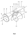
- Fig. 3 and 4 show a spatial representation of a second embodiment of a holding device 11. According to their function and / or structural design corresponding o. ⁇ . Constructive details are marked with the same reference numerals.
- the holding device 11 is formed with an example cast housing 27, which deviates from the embodiment according to Fig. 2
- the housing 27 has a first approximation tube-like geometry with an extension in the form of a funnel 28 in the direction of the opening 25.
- the receptacle 19 of the holding device 11 according to Fig. 3 and 4 Both the guide member 12 forming slot 13 and the Spulgut exit slot 16 are not open edge designed for this embodiment in the bottom portion 29, but rather edge-closed.
- the holding device 11 has a further slot 30, which is oriented transversely to the insertion direction 20, here in the circumferential direction of the housing 28.
- the slot 30 opens into an end region in the Spulgut exit slot 16 and in the other end in the slot 13.
- the slots 13, 30 and the Spulgut exit slot 16 in rough simplification an H-shaped opening, wherein the Spulgut exit slot 16 and the slot 13 form vertical leg of the H and the slot 30 forms the horizontal leg of the H.
- a sensor 31 is arranged, which passes through the housing 27 into the receptacle 19 for the illustrated embodiment.
- any type of sensor can be used, for example a mechanical switch actuated with the introduction of the winding material suction gun or a contactless sensor such as a Hall sensor, a reed contact or the like.
- the cutting device 26 is integrated into the holding device 11 for the second embodiment of the holding device 11.
- the cutting device 26 limits the Spulgut output slot 16 so that the Spulgut interacts with the cutting device 26 when this is forced along the Spulgut exit slot 16 in the direction of the bottom portion 29.
- the cutting device 26 is a plate-like cutting element, which is screwed by a fastening screw from the outside in a position to the holding device 11, in which the periphery forming a cutting edge slightly covers the Spulgut exit slot 16 from the outside.
- the deflection means 3 On the side facing away from the Changierspulgut ancestral 5 side of the holding device 11, the deflection means 3, here the guide roller 4 upstream, which is supported with a fixed predetermined axis of rotation 32 in the figures, not shown fasteners, support o. ⁇ .
- the housing 27 In the end region facing away from the opening 25 or in the bottom region 29, the housing 27 has suitable bores 33, via which the holding device can be coupled directly to the winding machine, in particular the Spulgutleitwerk 10 or coupled with the winding machine 1 with the interposition of other support elements.
- the coupling is made such that the axis of rotation 32 of the roller 4 is oriented so that from the lateral surface of the roller 4, the winding material through the slot 13, the Spulgut-passage space 15 and the Spulgut exit slot 16 without contact with the housing 28 to the traversing 5 can get.
- a fastening element 41 of the holding device 11 is formed.
- Fig. 5 schematically shows how the Spulgut 2 enters in a winder according to the invention without contact with the housing 27 in the region of the guide member 12, here the slot 13 in the Spulgut-passage chamber 15 and the holding device 11 leaves through the Spulgut exit slot 16 and rectilinear longitudinal axis as a result of the bias to the traversing 5 Wickierspulgutterrorism passes.
- Fig. 6 shows the laying of the thread in the laying triangle 34 as a result of the traversing movement 21 of the Changierspulgut concernss 5.
- the Spulgut 2 is passed without contact with the housing 27 through the slot 13 and the Spulgut exit slot 16, including the length of slot 13 and the Spulgut exit slot 16 is sized accordingly.
- this is the Spulgut in the slot 13 and the Spulgut exit slot 16 approximately at the place where opens into this slot 30.
- the winding material through the upper boundary of the slot 13 and the Spulgut exit slot 16 out.
- the product 2 still has a distance 35 from the cutting edge of the cutting device 26.
- Fig. 7 shows in a front view in viewing direction in the insertion direction 20, the holding device 11 with guide roller 4 and housing 27, wherein due to the edge opening 18, the Spulgut 2 can be seen in the Spulgut exit slot 16, while the entry of the Spulguts in the slot 13 in this view can be seen, since this slot 13 is closed at the edge.
- the end face 39 of the suction nozzle 37 with adjacent thereto Spulgut 2 pressed against a stopper member 40 to initiate the cutting operation by the cutter 26.
- This has the consequence that the friction acting on the Spulgut 2 between stop member 40 and end face 39 increases, which in turn has the consequence that increases the tension of the Spulguts 2 between the end face 39 and stop member 40 and the traversing 5.
- This increased tension has the consequence that the winding material 2 is pulled with a greater force against the cutting edge of the cutting device 26, whereby the severing is then caused.
- the funnel-shaped extension of the housing 27 forms an insertion region 42 for the winding material suction gun.
- a winder 1 is shown with only one winding station 43, where quite in a winder 1 and several winding stations can be operated in parallel.
- the holding device 11 according to the invention is used as an initial equipment for the winder 1 with their delivery to the customer.
- the holding device 11 according to the invention is marketed as a retrofit product for already previously distributed winding machines 1 and is used.
- a control device that a severing of the Spulguts 2 is carried out, which with a time delay or a deceleration of Spool 7 and / or unlocking the sleeve 8 can be triggered by the spindle 9.
- additional can be evaluated, an output signal of the sensor 31, by means of which it is detected how far the suction nozzle 37 of the winding material suction gun 44 is inserted into the receptacle 19.
- a holding device 45 can provide both the holding device 11 and the last of these upstream deflection means 3 as a compact structural unit.
- slot and "exit slot” any embodiment with rectilinear or curved longitudinal axis and the same or varying slot width is included.
- the Spulgut suction gun 44 rests locked or secured by friction.
Abstract
Description
Die Erfindung betrifft eine Haltevorrichtung für eine Spulgut-Saugpistole. Weiterhin betrifft die Erfindung eine Halteeinrichtung mit einer derartigen Haltevorrichtung sowie eine Spulmaschine mit einer Haltevorrichtung für eine Spulgut-Saugpistole. Die Erfindung betrifft auch ein Verfahren zum Überführen eines Spulguts am Ende eines Wickelvorgangs einer ersten Spule auf einer Spulstation einer Spulmaschine zu einer zweiten Spule, die auf derselben Spulstation der Spulmaschine mitgewickelt wird, wobei eine Spulgut-Saugpistole und eine Haltevorrichtung für diese zum Einsatz kommen.The invention relates to a holding device for a Spulgut suction gun. Furthermore, the invention relates to a holding device with such a holding device and a winding machine with a holding device for a Spulgut suction gun. The invention also relates to a method for transferring a Spulguts at the end of a winding process of a first coil on a winding station of a winder to a second spool, which is co-wound on the same winding station of the winder, wherein a Spulgut suction gun and a holding device for this are used.
Bekannt sind Spulgut-Saugpistolen, welche zur Handhabung eines Spulguts bei der Herstellung des Spulguts und dem Wickeln des Spulguts durch eine Spulmaschine Einsatz finden. Mittels der Spulgut-Saugpistole wird ein saugender Luftstrom herbeigeführt, über welchen Kräfte auf das Spulgut ausgeübt werden können, das Spulgut im Bereich einer Saugöffnung der Spulgut-Saugpistole gefangen werden kann und/oder das Spulgut mit dem Luftstrom in eine Öffnung, einen Kanal oder einen Aufnahmebehälter der Spulgut-Saugpistole "abgesaugt" werden kann. Im Folgenden werden diese Funktionen erfüllende Saugeinrichtungen als "Spulgut-Saugpistole" bezeichnet unabhängig davon, ob diese als eine Art "Pistole" oder in anderer konstruktiver Ausgestaltung ausgebildet sind. Einsatz finden können Spulgut-Saugpistolen beispielsweise, wenn sich in einer Spulmaschine eine Störung ergibt, so dass ein in einem kontinuierlichen Herstellungsverfahren hergestelltes, kontinuierlich zugeführtes Spulgut durch die Spulmaschine nicht kontinuierlich abgenommen werden kann. In diesem Fall kann das Spulgut über die Spulgut-Saugpistole kontinuierlich abgesaugt werden. Befindet sich ein Spulgut im Einzugsbereich einer Spulgut-Saugpistole, kann das Spulgut auch über die Spulgut-Saugpistole einem gewünschten Ort zugeführt werden. Insbesondere kann über die Spulgut-Saugpistole das Spulgut der Spulmaschine zugeführt werden und beispielsweise einer geeigneten Fangeinrichtung einer rotierenden Spindel der Spulmaschine oder einer Fangeinrichtung einer von einer Spindel angetriebenen Hülse zugeführt werden. Eine derartige Spulgut-Saugpistole ist beispielsweise aus
Während der eigentliche Spulvorgang in Vollautomatisierung gut beherrschbar ist, ergeben sich Probleme bei dem manuell herbeigeführten Wechsel beim Ende des Spulvorgangs einer ersten Spule zu einem anschließenden Spulvorgang für eine zweite Spule. Hierzu ist es erforderlich, am Ende des Spulvorgangs das kontinuierlich zulaufende Spulgut manuell zu durchtrennen, was üblicherweise zwischen dem Changierspulgutführer und dem diesem vorgeordneten Fadenführer, insbesondere einem Umlenkbügel oder einer Umlenkrolle, erfolgt. Nach dem Durchtrennen des Spulguts wird das auf die Spule laufende Ende des Spulguts auf diese aufgewickelt, während mittels einer Spulgut-Saugpistole das weiterhin zulaufende Spulgut abgesaugt und aufgenommen wird. Hieran anschließend wird das Spulgutleitwerk mit der Anpresswalze von der vollen ersten Spule wegbewegt. Die Spule wird abgebremst und eine etwaige Verriegelung der Spule auf der Spindel wird beseitigt, wodurch ein Abnehmen der Spule von der Spindel ermöglicht wird. Es kann dann eine neue leere Hülse auf die Spindel aufgebracht werden, die dann ggf. mit der Spindel verriegelt wird und durch diese in Rotation versetzt wird. Mittels der Spulgut-Saugpistole kann dann eine Handhabung des Spulguts derart erfolgen, dass das Spulgut der leeren Hülse oder einer geeigneten Fangeinrichtung der Hülse oder der Spindel zugeführt wird. Dann wird das Spulgut zwischen Spindel oder Hülse bzw. zweiter Spule und Spulgut-Saugpistole durchtrennt, womit der Wickelvorgang für die zweite Spule beginnen kann. Problematisch hierbei ist, dass während des zuvor geschilderten Wechselvorgangs der Bediener der Spulmaschine die Absaugpistole in der Hand halten muss, womit diesem lediglich nur noch eine Hand zur Verfügung steht, um die erste Spule von der Spindel zu entfernen und die leere Hülse auf die Spindel aufzubringen und die Spulmaschine zu bedienen. Unter Umständen bedingt dies die Durchführung des Spulenwechsels mit zwei Personen. Möglich ist auch, dass der Bediener die Spulgut-Saugpistole ablegt und später wieder aufnimmt, was jedoch umständlich ist. In jedem Fall ist die Position der Spulgut-Saugpistole, und damit ein Referenzpunkt des kontinuierlich zulaufenden Spulguts, in das Belieben des Benutzers gestellt. Die räumliche Bewegung der Spulgut-Saugpistole, über welche diese zunächst das Spulgut zwischen Changierspulgutführer und Umlenkmittel fangen muss, dann während des ersten Durchtrennens das Spulgut hält, dann an einem abseits gelegenen Ort das Spulgut einer Fangeinrichtung der Spindel oder Hülse der zweiten Spule zuführt und dann das zweite Durchtrennen ermöglicht, ist ebenfalls in das Belieben des Benutzers gestellt. Dies hat in der Praxis immer wieder zur Folge, dass während des Wechselvorgangs das Spulgut ein Umlenkmittel, eine Umlenkrolle oder eine Tänzerrolle unerwünscht verlässt. Im günstigsten Fall muss der Bediener in einem derartigen Fall mittels der Spulgut-Saugpistole das Spulgut wieder über Umlenkrolle, Tänzerrolle und/oder Umlenkmittel führen, was dessen volle Aufmerksamkeit erfordert und einen zusätzlichen Zeitaufwand erfordert, in welchem kontinuierlich Spulgut produziert wird, welches nicht zu einer Spule gewickelt werden kann. Schlimmstenfalls kommt es angesichts des nicht ordnungsgemäß geführten Spulguts zu einer Maschinenstörung.While the actual winding process can be easily controlled in full automation, problems arise in the manually induced change at the end of the winding process of a first bobbin to a subsequent winding process for a second bobbin. For this purpose, it is necessary to manually cut at the end of the winding process, the continuously tapered winding material, which usually takes place between the traversing yarn guide and this upstream yarn guide, in particular a deflection bar or a guide roller. After severing the Spulguts the running on the bobbin end of the Spulguts is wound on this, while sucked by a Spulgut-suction gun, the further tapered Spulgut and is absorbed. Following this, the Spulgutleitwerk is moved away with the pressure roller of the full first coil. The spool is decelerated and any locking of the spool on the spindle is eliminated, thereby allowing the spool to be removed from the spindle. It can then be applied to the spindle a new empty sleeve, which is then optionally locked with the spindle and is rotated by them. By means of the Spulgut suction gun can then be done such a handling of the Spulguts the Spulgut the empty shell or a suitable catching device of the sleeve or the spindle is supplied. Then the Spulgut between spindle or sleeve or second coil and Spulgut suction gun is severed, so that the winding process for the second coil can begin. The problem here is that during the previously described change process, the operator of the winding machine must hold the suction in his hand, which this only one hand is available to remove the first coil of the spindle and apply the empty sleeve on the spindle and to operate the winder. Under certain circumstances, this requires the implementation of the bobbin change with two people. It is also possible that the operator deposits the Spulgut-suction and resumed later, which is cumbersome. In any case, the position of the Spulgut-suction gun, and thus a reference point of the continuous Spulguts, placed in the discretion of the user. The spatial movement of the Spulgut suction gun, which must first catch the Spulgut between traversing and Changierspulgutführer, then holds the Spulgut during the first cutting, then at a remote location the Spulgut a catching device of the spindle or sleeve of the second coil supplies and then the second cutting is also made at the discretion of the user. This has the result in practice again and again that during the changing process, the Spulgut undesirably leaves a deflection, a pulley or a dancer roll. In the best case, the operator must lead in such a case by means of Spulgut suction gun the Spulgut about diverting pulley, dancer roll and / or deflection, which requires his full attention and requires additional time, in which continuous material is produced, which is not one Coil can be wound. In the worst case, it comes in the face of improperly managed Spulguts to a machine failure.
Der vorliegenden Erfindung liegt die Aufgabe zugrunde, eine Haltevorrichtung und eine Halteeinrichtung sowie eine Spulmaschine mit einer derartigen Haltevorrichtung vorzuschlagen, welche den Wechsel des Wickelvorgangs einer ersten Spule zu einer zweiten Spule an einer Spulstation einer Spulmaschine vereinfacht und/oder weniger fehleranfällig macht. Weiterhin liegt der Erfindung die Aufgabe zugrunde, ein vereinfachtes Verfahren zum Überführen eines Spulguts am Ende eines Wickelvorgangs einer ersten Spule zu einer zweiten Spule vorzuschlagen, welches insbesondere hinsichtlich der Prozesssicherheit und dem manuellen Aufwand verbessert ist.The present invention has for its object to provide a holding device and a holding device and a winder with such a holding device, which simplifies the change of the winding process of a first coil to a second coil at a winding station of a winder and / or makes less error prone. Furthermore, the invention has for its object to propose a simplified method for transferring a Spulguts at the end of a winding process of a first coil to a second coil, which is improved in particular with regard to process reliability and manual effort.
Die Aufgabe der Erfindung wird erfindungsgemäß mit einer Haltevorrichtung mit den Merkmalen des unabhängigen Patentanspruchs 1 gelöst. Weitere erfindungsgemäße Ausgestaltungen einer derartigen Haltevorrichtung ergeben sich entsprechend den abhängigen Patentansprüchen 2-13. Eine weitere Lösung der der Erfindung zugrunde liegenden Aufgabe stellte eine Halteeinrichtung nach Anspruch 14 dar. Eine weitere Lösung der der Erfindung zugrunde liegenden Aufgabe ist gegeben durch eine Spulmaschine mit den Merkmalen des Patentanspruchs 15. Eine weitere Lösung der der Erfindung zugrunde liegenden Aufgabe ist gegeben durch ein Verfahren mit den Merkmalen des nebengeordneten Patentanspruchs 16. Weitere Ausgestaltungen eines derartigen Verfahrens ergeben sich entsprechend den abhängigen Patentansprüchen 17 und 18.The object of the invention is achieved with a holding device with the features of
Erfindungsgemäß wird erstmals vorgeschlagen, dass eine Haltevorrichtung für eine Spulgut-Saugpistole eingesetzt wird. Diese Haltevorrichtung gibt einen definierten Ort vor, an welchem der Bediener die Spulgut-Saugpistole anordnen kann, die Hände von der Spulgut-Saugpistole entfernen kann und, beispielsweise nach einigen Arbeitsschritten, dann wieder die Spulgut-Saugpistole aufnehmen kann.According to the invention it is proposed for the first time that a holding device for a winding material suction gun is used. This fixture specifies a defined location at which the operator can arrange the Spulgut-suction gun, can remove the hands of the Spulgut-suction gun and, for example, after a few steps, then again record the Spulgut-suction.
In der erfindungsgemäßen Haltevorrichtung kann die Spulgut-Saugpistole auch in saugendem Zustand gehalten werden, in welchem diese also kontinuierlich zugeführtes Spulgut aufnimmt.In the holding device according to the invention, the Spulgut suction gun can be kept in an absorbent state, in which this so receives continuously supplied Spulgut.
Die erfindungsgemäße Haltevorrichtung besitzt eine beliebig gestaltete Aufnahme für die Spulgut-Saugpistole. Die Aufnahme gibt hierbei eine Einführrichtung für die Spulgut-Saugpistole vor.The holding device according to the invention has an arbitrarily shaped receptacle for the Spulgut suction gun. The recording here is an introduction for the Spulgut suction gun.
Weiterhin verfügt die erfindungsgemäße Haltevorrichtung über ein Befestigungselement, mittels dessen die Haltevorrichtung an einer definierten Position und in vorgegebener Ausrichtung an einer Spulmaschine befestigt werden kann. Hierbei kann die Haltevorrichtung über das Befestigungselement beispielsweise an einem Spulgutleitwerk oder auch an einem Gehäuse der Spulmaschine befestigt sein. Um hier lediglich einige Beispiele zu nennen, kann es sich bei dem Befestigungselement der Haltevorrichtung um einen Befestigungsflansch, einen Befestigungsträger, Bohrungen, Langlöcher, Gewinde o. ä. handeln.Furthermore, the holding device according to the invention has a fastening element by means of which the holding device can be fastened to a winding machine at a defined position and in a predetermined orientation. In this case, the holding device can be attached via the fastening element, for example, to a Spulgutleitwerk or to a housing of the winder. To name just a few examples here, the attachment element of the holding device may be a mounting flange, a mounting carrier, bores, elongated holes, threads or the like.
Darüber hinaus verfügt die Haltevorrichtung über ein Führungsorgan. Dieses Führungsorgan gibt einen Eintrittsbereich des Spulguts in die Haltevorrichtung vor. Das Führungsorgan hält damit auch das Spulgut in dem gewünschten Eintrittsbereich der Haltevorrichtung, wenn die Spulgut-Saugpistole aus der Haltevorrichtung entnommen wird und frei außerhalb derselben bewegt wird, beispielsweise in Richtung der Spindel, um den Wechsel durchzuführen. Hierbei ist die Lage des Eintrittsbereichs in die Haltevorrichtung derart gewählt, dass gewährleistet ist, dass stromaufwärts des Eintrittsbereichs das Spulgut nicht etwaige Umlenkmittel, Umlenkrollen u. ä. verlassen, womit die eingangs erläuterten Probleme beseitigt sind.In addition, the holding device has a guide member. This guide member defines an entrance area of the Spulguts in the holding device. The guide member thus holds the Spulgut in the desired entry area of the holding device when the Spulgut suction gun is removed from the holding device and is moved freely outside the same, for example in the direction of the spindle to perform the change. Here, the position of the entry region is selected in the holding device such that it is ensured that upstream of the entry region, the Spulgut not any deflection means, pulleys u. Ä. Leave, whereby the problems explained above are eliminated.
Schließlich besitzt die erfindungsgemäße Haltevorrichtung einen Spulgut-Ausgangsschlitz. Dieser ist entgegen der Einführrichtung der Spulgut-Saugpistole in die Aufnahme der Haltevorrichtung randoffen ausgebildet. Vorzugsweise mündet der Spulgut-Ausgangsschlitz in die Öffnung der Haltevorrichtung, durch die die Spulgut-Saugpistole in die Aufnahme eingeführt wird. Wird die Spulgut-Saugpistole in die Aufnahme der Haltevorrichtung eingebracht und dann das Spulgut in die Spulgut-Saugpistole eingesaugt, könnte die Spulgut-Saugpistole ohne den erfindungsgemäßen Spulgut-Ausgangsschlitz nicht aus der Haltevorrichtung herausgenommen werden und in Richtung der Spindel der Spulmaschine bewegt werden, ohne dass das Spulgut in der Haltevorrichtung mehrfach umgelenkt werden würde, was zu Beeinträchtigungen des Spulguts bis hin zu einem Reißen des Spulguts führen könnte. Hingegen ermöglicht der Spulgut-Ausgangsschlitz, dass die Spulgut-Saugpistole mit hiervon angesaugtem Spulgut aus der Haltevorrichtung entnommen wird und mit der Bewegung der Spulgut-Saugpistole in Richtung der Spindel das Spulgut zumindest ohne Kontakt des Spulguts mit der Haltevorrichtung auf der der Spindel zugewandten Seite durch die Haltevorrichtung hindurchtreten kann. Anders gesagt ermöglicht der Spulgut-Ausgangsschlitz, dass die Spulgut-Saugpistole mit in dieser einlaufendem Spulgut aus der Haltevorrichtung entnommen werden kann und außerhalb derselben bewegt werden kann, ohne dass eine übermäßige Zahl von Kontaktstellen mit der Haltevorrichtung oder Umlenkstellen existiert.Finally, the holding device according to the invention has a Spulgut output slot. This is formed open against the insertion of the Spulgut suction gun into the receptacle of the holding device. Preferably, the Spulgut output slot opens into the opening of the holding device, through which the Spulgut-suction gun is inserted into the receptacle. If the Spulgut-suction gun is introduced into the receptacle of the holding device and then sucked the Spulgut in the Spulgut suction gun, the Spulgut suction gun could not be removed from the holding device without the Spulgut exit slot according to the invention and moved in the direction of the spindle of the winder, without that the material to be spooled would be deflected several times in the holding device, which could lead to impairments of the Spulguts up to a rupture of the Spulguts. By contrast, the Spulgut output slot allows the Spulgut suction gun is taken with this sucked Spulgut from the fixture and with the movement of the Spulgut suction gun in the direction of the spindle Spulgut at least without contact of the Spulguts with the holding device on the spindle side facing the holding device can pass. In other words, the Spulgut output slot allows the Spulgut suction gun can be removed with this incoming Spulgut from the holding device and can be moved outside the same without an excessive number of contact points with the holding device or deflection exists.
Für eine erste Ausführungsform der Erfindung ist der Spulgut-Ausgangsschlitz durchgehend ausgebildet und beidseitig randoffen. Möglich ist auch, dass die Haltevorrichtung beidseitig offen ist, so dass die Spulgut-Saugpistole durch eine Öffnung in die Haltevorrichtung eingeführt werden kann und im Extremfall auf der gegenüberliegenden Seite aus der Haltevorrichtung auskragen kann. Der Spulgut-Ausgangsschlitz kann dann die beiden genannten Öffnungen miteinander verbinden. Mit Entnahme der Spulgut-Saugpistole wird die Saugöffnung mit ihrem einlaufenden Spulgut durch die Aufnahme zurückgezogen, wobei dann für die freie Bewegung der Spulgut-Saugpistole außerhalb der Haltevorrichtung das Spulgut je nach Position der Spulgut-Saugpistole entlang des Spulgut-Ausgangsschlitzes "wandern" kann.For a first embodiment of the invention, the Spulgut output slot is formed continuously and open on both sides. It is also possible that the holding device is open on both sides, so that the Spulgut suction gun can be inserted through an opening in the holding device and can protrude in extreme cases on the opposite side of the holding device. The Spulgut exit slot can then connect the two openings mentioned together. With removal of the Spulgut suction gun, the suction opening with her incoming Spulgut withdrawn through the recording, in which case for the free movement of the Spulgut suction gun outside of the holding device, the Spulgut depending on the position of the Spulgut suction gun along the Spulgut exit slot "wander" can.
Für eine zweite Ausführungsform der Erfindung sind die Aufnahme und die Erstreckung der Haltevorrichtung derart dimensioniert, dass in in die Aufnahme eingestecktem Zustand der Spulgut-Saugpistole die Saugöffnung der Spulgut-Saugpistole in einem Spulgutdurchtrittsraum der Haltevorrichtung angeordnet ist. Der Spulgut-Durchtrittsraum besitzt quer zur Einführrichtung der Spulgut-Saugpistole Öffnungen. Während des normalen Betriebs der Spulmaschine kann im Idealfall das Spulgut die Öffnungen und den Spulgut-Durchtrittsraum durchlaufen, ohne dass überhaupt ein Kontakt mit der Haltevorrichtung existiert. Für diese Ausführungsform kann die Haltevorrichtung auch in Einführrichtung hinter dem Spulgut geschlossen ausgebildet sein. Vorzugsweise sind die genannten Öffnungen mit dem Spulgut-Ausgangsschlitz und dem Führungsorgan ausgebildet oder diese münden ineinander.For a second embodiment of the invention, the receptacle and the extent of the holding device are dimensioned such that in the receptacle inserted state of the Spulgut suction gun, the suction opening of the Spulgut suction gun is arranged in a Spulgutdurchtrittsraum the holding device. The Spulgut-passage space has transverse to the direction of insertion of the Spulgut suction gun openings. During normal operation of the winder, ideally, the wad may pass through the apertures and the wadding passage space without any contact with the retainer. For this embodiment, the holding device may be formed closed in the insertion behind the Spulgut. Preferably, said openings are formed with the Spulgut output slot and the guide member or these open into one another.
In weiterer Ausgestaltung dieser Ausführungsform der Erfindung sind das Befestigungselement und die Aufnahme derart dimensioniert und orientiert, dass die Einführrichtung der Aufnahme für die Spulgut-Saugpistole der Changierrichtung eines Changierspulgutführers entspricht. Dieser Ausgestaltung liegt der Erkenntnis zugrunde, dass unter Umständen ungewiss ist, wo sich der Changierspulgutführer am Ende des Wickelvorgangs für die erste Spule gerade befindet. Ist die Einführrichtung der Haltevorrichtung für die Spulgut-Saugpistole parallel zur Changierrichtung orientiert, führt eine unterschiedliche Position des Changierspulgutführers gegen Ende des Wickelvorgangs lediglich dazu, dass eine Wechselwirkung zwischen der Spulgut-Saugpistole und dem Spulgut für unterschiedliche Einführtiefen der Spulgut-Saugpistole in die Aufnahme erzeugt wird, aber in jedem Fall die Saugöffnung der Spulgut-Saugpistole das Spulgut "trifft". Hierdurch kann die Prozesssicherheit erhöht werden.In a further embodiment of this embodiment of the invention, the fastening element and the receptacle are dimensioned and oriented such that the insertion direction of the receptacle for the Spulgut suction gun corresponds to the traversing direction of a traversing Spulgutführers. This embodiment is based on the knowledge that it may be uncertain where the traversing spool guide is located at the end of the winding process for the first spool. If the insertion direction of the holding device for the winding material suction gun is oriented parallel to the traversing direction, a different position of the traversing yarn guide towards the end of the winding process merely causes an interaction between the winding material suction gun and the winding material to be produced for different insertion depths of the winding suction gun into the receptacle is, but in any case, the suction opening of the Spulgut suction gun the Spulgut "hits". As a result, the process reliability can be increased.
Vorzugsweise weisen die Öffnungen des Spulgut-Führungsraums in einer Changierebene Erstreckungen auf, die größer sind als die maximale Bewegung des Spulguts im Bereich der Haltevorrichtung infolge der Bewegung des Changierspulgutführers. Diese Ausgestaltung hat zur Folge, dass unerwünschte Kontakte zwischen Spulgut und Haltevorrichtung während des Wickelvorgangs und der Changierbewegung des Changierspulgutführers ausgeschlossen sind, die zu einer Erhöhung der Reibung, einer Veränderung der Fadenspannung und einer Beeinträchtigung des Spulguts führen können.Preferably, the openings of the Spulgut-guide space in a traverse plane extensions which are greater than the maximum movement of the Spulguts in the region of the holding device due to the movement of the traversing Spulgutführers. This configuration has the consequence that unwanted contacts between Spulgut and holding device are excluded during the winding process and the traversing movement of the traversing Spulgutführers that can lead to an increase in friction, a change in the thread tension and deterioration of Spulguts.
In weiterer Ausgestaltung der Erfindung besitzt die Haltevorrichtung einen Einführbereich für die Aufnahme, beispielsweise mit einem Einführelement, einer Einführschräge oder einem Einführtrichter. Der Einführbereich kann das Einführen der Spulgut-Saugpistole für den Bediener vereinfachen und prozesssicherer gestalten.In a further embodiment of the invention, the holding device has an insertion region for the receptacle, for example with an insertion element, an insertion bevel or an insertion funnel. The insertion area can simplify the insertion of the winding material suction gun for the operator and make it more reliable.
Während durchaus möglich ist, dass ein Durchtrennen des Spulguts außerhalb der Haltevorrichtung durch an sich bekannte Maßnahmen erfolgt, ist gemäß einem weiteren Vorschlag der Erfindung die Haltevorrichtung mit einer Schneideinrichtung zur Durchtrennung des Spulguts ausgestattet. Hierbei kann es sich um eine beliebige Schneideinrichtung, beispielsweise ein Messer, ein beheiztes Trennelement, einen Laser o. ä. handeln. Somit kann erfindungsgemäß die Haltevorrichtung multifunktional ausgebildet werden, indem diese neben der zuvor erläuterten Halte- und Wechselfunktion sowie Führungsfunktion für das Spulgut für das Durchtrennen des Spulguts zuständig ist. In besonders vorteilhafter Ausgestaltung kommt die Schneideinrichtung bewegungsgesteuert durch die Bewegung der Spulgut-Saugpistole in der Aufnahme zur Wirkung. Um lediglich einige Beispiele zu nennen, kann mittels der Spulgut-Saugpistole bewegungsgesteuert ein Schneidmesser betätigt werden, welches quer zu dem Spulgut bewegt wird und dieses durchtrennt. Möglich ist auch, dass die Spulgut-Saugpistole das Spulgut "mitnimmt" und dieses gegen die Schneideinrichtung drückt mit hierdurch herbeigeführter Durchtrennung des Spulguts.While it is quite possible that a cutting of the Spulguts outside of the holding device is carried out by measures known per se, the holding device is equipped with a cutting device for cutting the Spulguts according to a further proposal of the invention. This may be any desired cutting device, for example a knife, a heated separating element, a laser or the like. Thus, according to the invention, the holding device can be designed to be multifunctional, in that it is responsible for the severing of the product to be spooled in addition to the previously described holding and changing function as well as the guiding function for the product to be spooled. In a particularly advantageous embodiment, the cutting device comes movement controlled by the movement of the Spulgut suction gun in the recording to effect. To name just a few examples, a cutting blade can be actuated by means of the winding material suction gun, which is moved transversely to the winding material and cuts it. It is also possible that the Spulgut-suction gun "takes" the Spulgut and this presses against the cutting device with thereby brought about cutting the Spulguts.
Während grundsätzlich beliebige offene, skelettartige, trägerartige, teilgeschlossene oder geschlossene Ausbildungen der Haltevorrichtung möglich sind, schlägt die Erfindung in weiterer Ausgestaltung vor, dass die Haltevorrichtung mit einem hohlen, einseitig offenen Gehäuse ausgebildet ist. Ein Innenraum des hohlen Gehäuses bildet hierbei die Aufnahme, wobei dann die Spulgut-Saugpistole durch die offene Seite des Gehäuses in die Aufnahme eingebracht werden kann.While basically any open, skeletal, carrier-like, partially closed or closed configurations of the holding device are possible, the invention proposes in a further embodiment, that the holding device is formed with a hollow housing open on one side. An interior of the hollow housing in this case forms the receptacle, in which case the Spulgut suction gun can be introduced through the open side of the housing in the recording.
Grundsätzlich ist jede Haltevorrichtung im Rahmen der Erfindung einsetzbar, welche das erstmalige Einführen des Spulguts ermöglicht, das Durchführen des Spulguts ermöglicht, mittels des Führungsorgans den Eintrittsbereich des Spulguts vorgibt und mit dem Spulgut-Ausgangsschlitz überflüssige Umlenkungen des Spulguts beim Wechsel vermeidet. Für einen besonderen Vorschlag der Erfindung ist ein Gehäuse der Haltevorrichtung im Bereich seiner Mantelfläche mit einer in die Aufnahme mündenden H-förmigen Durchbrechung ausgestattet. Hierbei sind die beiden Vertikalschenkel sowie der Horizontalschenkel des H jeweils mit Schlitzen gebildet. Der Schlitz, der den Horizontalschenkel bildet, ist in Umfangsrichtung der Aufnahme orientiert. Erstreckt sich dieser Schlitz ungefähr in Laufrichtung des Spulguts im Bereich der Haltevorrichtung, kann über diesen Schlitz das Spulgut von oben in die Haltevorrichtung einführt werden. Hingegen sind die die Vertikalschenkel des H bildenden Schlitze parallel zur Einführrichtung, also vorzugsweise in Changierrichtung orientiert. Der den Horizontalschenkel des H bildende Schlitz mündet endseitig in die die Vertikalschenkel des H bildenden Schlitze, so dass nach dem Einführen des Spulguts durch den erstgenannten Schlitz das Spulgut in die beiden die Vertikalschenkel des H bildenden Schlitze eintreten kann. Durchläuft das Spulgut diese beiden Schlitze in der Haltevorrichtung, ermöglichen die Schlitze eine Bewegung des Spulguts während des Changiervorgangs ohne Kontakt des Spulguts mit den Begrenzungen der Schlitze. Hierbei bildet einer der Schlitze, die den Vertikalschenkel des H bilden, nämlich der Schlitz, welcher der Spindel zugewandt ist, den Spulgut-Ausgangsschlitz, während der andere einen Vertikalschenkel des H bildende Schlitz, nämlich der auf der Spindel abgewandten Seite angeordnete Schlitz, das Führungsorgan bildet. Mittels der H-förmigen Durchbrechung können auf besonders einfache Weise die erfindungsgemäßen Maßnahmen realisiert werden, wobei durch Gestaltung der H-förmigen Durchbrechung und der Querabmessungsverläufe der Schlitze und die Orientierung und Krümmung der Längsachsen der Schlitze auf das Führungsverhalten für das Spulgut im Bereich der Haltevorrichtung konstruktiv eingewirkt werden kann.In principle, any holding device can be used within the scope of the invention, which makes it possible to insert the product for the first time, allows the product to be taken through, predetermines the entry region of the product by means of the guide element and avoids unnecessary deflections of the product to be taken during the change with the product exit slit. For a particular proposal of the invention, a housing of the holding device in the region of its lateral surface is equipped with an opening into the receptacle H-shaped opening. Here are the two vertical leg and the horizontal leg of the H respectively Slits formed. The slot which forms the horizontal leg is oriented in the circumferential direction of the receptacle. Extending this slot approximately in the direction of Spulguts in the region of the holding device, the Spulgut can be introduced from above into the holding device via this slot. On the other hand, the slots forming the vertical limbs of the H are parallel to the insertion direction, that is to say preferably oriented in the traversing direction. The slot forming the horizontal limb of the H ends ends in the slots forming the vertical limbs of the H, so that after the introduction of the product to be winder through the first-mentioned slot, the wadding can enter the two slots forming the vertical limbs of the H. If the material to be winder passes through these two slots in the holding device, the slots allow the product to be moved during the traversing process without contact of the product with the boundaries of the slots. Here, one of the slots which form the vertical leg of the H, namely the slot which faces the spindle, the Spulgut exit slot, while the other one vertical leg of the H forming slot, namely the side facing away from the spindle slot, the guide member forms. By means of the H-shaped opening measures according to the invention can be realized in a particularly simple manner, wherein by designing the H-shaped aperture and the Querabmessungsverläufe the slots and the orientation and curvature of the longitudinal axes of the slots on the leadership behavior for the Spulgut in the holding device constructive can be acted upon.
Während die Haltevorrichtung (und die Aufnahme) grundsätzlich einen beliebigen Querschnitt besitzen kann (können), besitzt in weiterer Ausgestaltung die Haltevorrichtung einen kreisringförmigen Querschnitt, was vorzugsweise von Vorteil ist, wenn zumindest ein Teil der sich in die Aufnahme erstreckenden Spulgut-Saugpistole einen rohrartigen Querschnitt besitzt. In diesem Fall kann die Haltevorrichtung auch mit einem Einführbereich ausgestattet sein, der dann trichterförmig ausgebildet sein kann.While the holding device (and the receptacle) can basically have any desired cross-section, in a further embodiment the holding device has an annular cross-section, which is preferably advantageous if at least part of the winding material suction gun extending into the receptacle has a tubular cross-section has. In this case, the holding device may also be equipped with an insertion, which may then be funnel-shaped.
Grundsätzlich kann die Schneideinrichtung zum Durchtrennen des Spulguts bei dem Wechsel an beliebiger Stelle in- und außerhalb der Haltevorrichtung angeordnet sein. Für einen besonderen Vorschlag der Erfindung ist die Schneidvorrichtung in einem Endbereich des Spulgut-Ausgangsschlitzes angeordnet. Wird, beispielsweise mit der Spulgut-Saugpistole, das Spulgut bis in den Endbereich des Spulgut-Ausgangsschlitzen gebracht, kommt dieses bewegungsgesteuert zur Anlage an die Schneideinrichtung mit dem Durchtrennen des Spulguts. Da der Spulgut-Ausgangsschlitz auf der der Spindel zugewandten Seite der Haltevorrichtung angeordnet ist, kann das der Spindel zugewandte Ende des Spulguts ohne weitere Wechselwirkung mit der Haltevorrichtung auf der Spule aufgewickelt werden, während das "stromaufwärtige" Ende des Spulguts in der Haltevorrichtung durch die Spulgut-Saugpistole gefangen und abgesaugt werden kann. Während des Fangens des Spulguts kann eine Spulgutlänge zwischen Schneideinrichtung und Eintritt des Spulguts in die Haltevorrichtung eine geeignete Angriffsfläche für den saugenden Luftstrom der Spulgut-Saugpistole bilden.In principle, the cutting device for severing the Spulguts can be arranged in the change at any point inside and outside of the holding device. For a particular proposal of the invention, the cutting device is arranged in an end region of the Spulgut output slot. If, for example, with the Spulgut suction gun, the Spulgut brought into the end of the Spulgut output slots, this comes movement controlled to the plant to the cutter with the severing of the Spulguts. Since the Spulgut exit slot arranged on the spindle side facing the holding device is, the spindle facing the end of the Spulguts can be wound without further interaction with the holding device on the spool, while the "upstream" end of the Spulguts can be caught and sucked in the holding device by the Spulgut suction gun. While catching the Spulguts a Spulgutlänge between cutting device and entry of the Spulguts in the holding device form a suitable attack surface for the sucking air flow of the Spulgut suction gun.
In weiterer Ausgestaltung der Erfindung kann die Haltevorrichtung über einen Sensor verfügen. Der Sensor kann eine Position, eine Bewegung, eine Anpresskraft und/oder ein Vorhandensein einer Spulgut-Saugpistole in der Aufnahme erfassen. Möglich ist hierbei, dass der Sensor als digitaler Schalter ausgebildet ist oder ein kontinuierliches Signal bildet. Das Sensorsignal dieses Sensors kann dann zur Steuerung weiterer Vorgänge der Spulmaschine einer Steuereinrichtung zugeführt werden. Um hier lediglich einige Beispiele zu nennen, kann getriggert durch den Sensor die Betätigung einer Schneideinrichtung erfolgen, eine Beeinflussung des Zuführverhaltens für das Spulgut ausgangsseitig des Herstellungsprozesses, eine Beeinflussung des Antriebs von Changiereinrichtung, des Spulgutleitwerks, der Anpresskraft der Anpresswalze und/oder des Antriebs einer Spindel oder einer Anpresswalze zum Antrieb der Spule erfolgen. Insbesondere kann mit hinreichendem Einschieben der Spulgut-Saugpistole in die Aufnahme, mit welcher das automatisierte Durchtrennen des Spulguts ausgelöst wird, automatisiert der Wechsel der Spule eingeleitet werden, indem unmittelbar oder zeitverzögert ein Abbremsen der Spindel oder Spule erfolgt und, beispielsweise zeitverzögert oder mit Unterschreiten einer vorgegebenen Drehzahl der Spule eine Entriegelung zwischen Spule und Spindel erfolgen. Kommt die Spule zum Stillstand, kann der Bediener ohne zusätzliche weitere Maßnahmen die erste Spule von der Spindel beseitigen und eine neue Hülse auf die Spindel aufstecken. Detektiert dann der Sensor, dass der Bediener die Spulgut-Saugpistole aus der Aufnahme entfernt, kann die Steuereinheit automatisiert die Verriegelung von Hülse und Spindel durchführen und die Spindel in Rotation derart versetzen, dass ein Fangen des Spulguts erfolgen kann. Automatisiert kann dann auch erkannt werden, dass das Spulgut angelegt und gefangen ist: die Kraft, mit der das Spulgut von der Spulgut-Saugpistole abgesaugt wird, ist kleiner als die Kraft, die in dem Spulgut erzeugt wird, wenn das Spulgut gefangen und gewickelt wird. Eine geeignete Erfassungseinrichtung für die Spannung des Spulguts, insbesondere eine Erfassungseinrichtung für eine Auslenkung einer federnd gelagerten Tänzerrolle oder ein Kraftsensor an einer Rolle, kann somit aus einem Anstieg der Spannung des Spulguts automatisch das Fangen und den Beginn des Spulvorgangs detektieren, womit die Spulmaschine in den üblichen Regelvorgang für das Wickeln der Spule wechseln kann, u. U. auch mit Einsetzen der Changierbewegung. Der Benutzer kann dann die Spulgut-Saugpistole wieder in die Aufnahme einbringen und dort so lange bevorraten, bis der nächste Wechsel ansteht. Die vorgenannte Automatisierung stellt lediglich ein Beispiel für auf Grundlage eines Sensorsignals herbeiführbare Regelungs- und Automatisierungsmaßnahmen dar.In a further embodiment of the invention, the holding device may have a sensor. The sensor can detect a position, a movement, a pressing force and / or a presence of a winding material suction gun in the recording. It is possible here that the sensor is designed as a digital switch or forms a continuous signal. The sensor signal of this sensor can then be supplied to a controller for controlling further operations of the winder. To mention just a few examples here, triggered by the sensor, the operation of a cutting device, influencing the Zuführverhaltens for the Spulgut output side of the manufacturing process, influencing the drive of traversing device, the Spulgutleitwerks, the contact pressure of the pressure roller and / or the drive a Spindle or a pressure roller to drive the coil done. In particular, with sufficient insertion of the Spulgut-suction gun into the recording, with which the automated severing of Spulguts is triggered automatically the change of the coil can be initiated by directly or delayed deceleration of the spindle or spool takes place and, for example, time-delayed or falls below a predetermined speed of the coil unlocking between coil and spindle. If the bobbin comes to a standstill, the operator can remove the first bobbin from the spindle without additional measures and attach a new sleeve to the spindle. If the sensor then detects that the operator is removing the package suction gun from the receptacle, the control unit can automatically perform the locking of the sleeve and spindle and set the spindle in rotation in such a way that catching of the package can take place. Automated can then also be recognized that the Spulgut is created and captured: the force with which the Spulgut is sucked from the Spulgut-suction gun is smaller than the force generated in the Spulgut when the Spulgut is caught and wound , A suitable detection device for the tension of the Spulguts, in particular a detection device for a deflection of a spring-mounted dancer or a force sensor on a roller, thus can automatically detect the catch and the beginning of the winding process from an increase in the tension of the Spulguts, with which the winder in can change the usual control process for the winding of the coil, u. U. also with the onset of traversing movement. The user can then bring the Spulgut suction gun back into the receptacle and store there until the next change is pending. The aforementioned automation is merely an example of control and automation measures that can be brought about on the basis of a sensor signal.
Während durchaus denkbar ist, dass die Haltevorrichtung für sich ausgebildet ist und an einem Spulgutleitwerk oder einem anderen Bauelement der Spulmaschine an geeigneter Stelle stromabwärts eines Umlenkmittels oder einer Umlenkrolle angeordnet wird, kann die Haltevorrichtung auch Bestandteil einer Halteeinrichtung sein, die auch das Umlenkmittel ausbildet oder trägt. Dies vereinfacht die Montage, da die mit der Halteeinrichtung geschaffene Baueinheit mit integrierter Rolle bereits die richtige Ausrichtung von Haltevorrichtung, Führungsorgan und Rolle vorgibt.While it is quite conceivable that the holding device is designed for itself and is arranged on a Spulgutleitwerk or another component of the winding machine at a suitable point downstream of a deflection or a guide roller, the holding device may also be part of a holding device, which also forms or carries the deflection , This simplifies assembly, since the unit provided with the holding device with integrated roller already predetermines the correct alignment of holding device, guide member and roller.
Eine weitere Lösung der der Erfindung zugrunde liegenden Aufgabe ist gegeben durch eine Spulmaschine, die mindestens eine Spulstation besitzt, an welcher sukzessive Spulen mit einem Spulgut gewickelt werden, also nicht das Spulgut wechselseitig auf unterschiedliche Spindeln an unterschiedlichen Spulstationen aufgewickelt wird, wie dies insbesondere für Spulmaschinen mit mehreren, an einem Revolver angeordneten Spulstationen der Fall ist. Die erfindungsgemäße Spulmaschine verfügt über einen Changierspulgutführer sowie ein Umlenkmittel, welches dem Changierspulgutführer vorgeordnet ist, also "stromaufwärts" von diesem angeordnet ist. Eine Haltevorrichtung der zuvor beschriebenen Art für eine Spulgut-Saugpistole ist zwischen dem Changierspulgutführer und dem Umlenkmittel, insbesondere einer Umlenkrolle, angeordnet. Das Spulgut wird (während des Spulvorgangs) durch die Haltevorrichtung hindurchgeführt. Hierbei ist der Spulgut-Ausgangsschlitz der Haltevorrichtung auf der dem Changierspulgutführer zugewandten Seite angeordnet, so dass bei Entnahme der Spulgut-Saugpistole und Bewegung derselben in Richtung der Spindel das Spulgut eine gewisse Bewegung in dem Spulgut-Ausgangsschlitz machen kann, ohne dass das Spulgut zwingend an den Begrenzungen des Spulgut-Ausgangsschlitzes zur Anlage kommt. Hingegen ist das Führungsorgan der Haltevorrichtung auf der dem Umlenkmittel zugewandten Seite angeordnet, so dass dieses auf der richtigen Seite der Haltevorrichtung das Spulgut in einem Eintrittsbereich so hält, dass gewährleistet ist, dass das Spulgut das Umlenkmittel unabhängig von einer etwaigen Bewegung der Spulgut-Saugpistole nicht verlässt.Another solution to the problem underlying the invention is given by a winder, which has at least one winding station on which successive coils are wound with a Spulgut, so not the Spulgut is mutually wound on different spindles at different winding stations, as in particular for winding machines with several, arranged on a revolver winding stations is the case. The winding machine according to the invention has a traversing belt guide and a deflection, which is arranged upstream of the traversing yarn guide, that is "upstream" of this is arranged. A holding device of the type described above for a Spulgut suction gun is disposed between the traversing yarn guide and the deflection means, in particular a deflection roller. The Spulgut is passed (during the winding process) by the holding device. Here, the Spulgut output slot of the holding device is arranged on the side facing the Changierspulgutführer, so that when removing the Spulgut suction gun and movement thereof in the direction of the spindle Spulgut a certain movement in the Spulgut exit slot can make without the Spulgut imperative The limits of the Spulgut-output slot comes to rest. By contrast, the guide member of the holding device is arranged on the side facing the deflection, so that this holds on the right side of the holding device the Spulgut in an entry region, that ensures that the Spulgut the deflection independent of any movement of the Spulgut suction gun not leaves.
Eine weitere Lösung der Erfindung zugrunde liegenden Aufgabe ist gegeben durch ein Verfahren, mit welchem ein Überführen eines Spulguts am Ende eines Wickelvorgangs einer ersten Spule auf einer Spulstation einer Spulmaschine zu einer zweiten Spule auf derselben Spulstation der Spulmaschine erfolgt. Für ein derartiges Verfahren erfolgt u. U. zunächst gegen Ende des Wickelvorgangs der ersten Spule ein Einführen einer Spulgut-Saugpistole in eine Aufnahme einer Haltevorrichtung für die Spulgut-Saugpistole. Ebenfalls möglich ist allerdings, dass in der Haltevorrichtung die Spulgut-Saugpistole bereits während des Spulvorganges bevorratet ist. Vor, mit oder nach diesem Einführen erfolgt ein Aktivieren der Spulgut-Saugpistole. Es erfolgt das erste Durchtrennen des Spulguts, womit ein Ende zum Abschluss des Wickelvorgangs für die erste Spule freigegeben wird. Gleichzeitig wird das zulaufende Ende gefangen von der Spulgut-Saugpistole, die vor, mit oder nach dem Durchtrennen des Spulguts aktiviert wird/worden ist. Vor, während oder nach dem Abbremsen der ersten Spule und dem Entfernen der ersten Spule von der Spulstation erfolgt dann die Entnahme der Spulgut-Saugpistole aus der Haltevorrichtung. Während dann mit der Spulgut-Saugpistole außerhalb der Haltevorrichtung ein Ende des zulaufenden Spulguts frei geführt werden kann, wird das Spulgut zusätzlich durch ein Führungsorgan der Haltevorrichtung geführt. Die Führung erfolgt derart, dass sich das Spulgut unabhängig von der Bewegung des Spulguts mit der Spulgut-Saugpistole über das der Haltevorrichtung vorgeordnete Umlenkmittel läuft, also dieses nicht ungewollt verlassen kann. Anschließend erfolgt das Anlegen des Spulguts mit der Spulgut-Saugpistole für den Beginn des Wickelns der zweiten Spule, wobei das Anlegen unmittelbar an die Spindel erfolgen kann, sofern diese den Spulenkern ohne zusätzliche Hülse bildet, oder an eine Hülse erfolgt. Anschließend erfolgt ein zweites Durchtrennen des Spulguts, womit dann der Wickelvorgang für die zweite Spule erfolgt. Es versteht sich, dass die Reihenfolge der genannten Verfahrensschritte auch anders als zuvor beschrieben sein kann.Another object of the invention is based on a method with which a transfer of a product takes place at the end of a winding process of a first bobbin on a winding station of a winder to a second bobbin on the same winding station of the winder. For such a method u. U. initially at the end of the winding process of the first coil insertion of a Spulgut suction gun into a receptacle of a holding device for the Spulgut suction gun. However, it is also possible that in the holding device the Spulgut suction gun is already stored during the winding process. Before, with or after this insertion, the Spulgut suction gun is activated. There is the first cutting through the Spulguts, whereby one end is released to complete the winding process for the first coil. At the same time the tapered end is caught by the Spulgut-suction gun, which is activated / before, with or after the cutting of the Spulguts. Before, during or after the braking of the first coil and the removal of the first coil from the winding station then takes the removal of the Spulgut suction gun from the holding device. While then with the Spulgut suction gun outside of the holding device one end of the incoming Spulguts can be freely guided, the Spulgut is additionally guided by a guide member of the holding device. The guide is made such that the product to be spooled runs independently of the movement of the Spulguts with the Spulgut suction gun on the holding device upstream deflection, so this can not leave unintentionally. Subsequently, the application of the Spulguts done with the Spulgut suction gun for the beginning of the winding of the second coil, wherein the application can be made directly to the spindle, provided that it forms the spool without additional sleeve, or takes place on a sleeve. This is followed by a second severing of the Spulguts, which then takes place the winding process for the second coil. It is understood that the order of said method steps may also be different than previously described.
In weiterer Ausgestaltung des erfindungsgemäßen Verfahrens wird für das erste Durchtrennen des Spulguts die Spulgut-Saugpistole in der Aufnahme und relativ zu einer Schneideinrichtung bewegt, so dass das Durchtrennen bewegungsgesteuert durch die Spulgut-Saugpistole erfolgt.In a further embodiment of the method according to the invention for the first cutting of the Spulguts the Spulgut suction gun is moved in the receptacle and relative to a cutting device, so that the severing is motion-controlled by the Spulgut suction gun.
Für einen weiteren Vorschlag wird bei dem erfindungsgemäßen Verfahren über einen Sensor erfasst, ob sich die Spulgut-Saugpistole in der Aufnahme befindet, die Spulgut-Saugpistole in die Aufnahme eingeführt wird oder ist, eine Fadenspannung ansteigt oder abfällt, die Spulgut-Saugpistole aus der Aufnahme bewegt wird und/oder das erste Durchtrennen des Spulguts erfolgt. Mit dem Sensorsignal des Sensors erfolgt dann über eine geeignete Steuereinrichtung eine automatische Steuerung oder Regelung. Hierbei kann eine Regelung der Zuführgeschwindigkeit des Spulguts erfolgen, eine Ver- und/oder Entriegelungseinrichtung der Spindel mit einer Hülse oder Spule und/oder eines Antriebs der Spindel erfolgen, wie dies teilweise bereits zuvor erläutert worden ist.For a further proposal is detected in the inventive method via a sensor, whether the Spulgut suction gun is in the recording, the Spulgut suction gun is inserted into the receptacle or is a thread tension increases or decreases, the Spulgut-suction gun from the recording is moved and / or the first cutting of the Spulguts takes place. The sensor signal of the sensor then takes place via a suitable control device an automatic control or regulation. Here, a regulation of the feed rate of Spulguts done, a locking and / or unlocking the spindle with a sleeve or coil and / or a drive of the spindle done, as has been partially already explained above.
Vorteilhafte Weiterbildungen der Erfindung ergeben sich aus den Patentansprüchen, der Beschreibung und den Zeichnungen. Die in der Beschreibungseinleitung genannten Vorteile von Merkmalen und von Kombinationen mehrerer Merkmale sind lediglich beispielhaft und können alternativ oder kumulativ zur Wirkung kommen, ohne dass die Vorteile zwingend von erfindungsgemäßen Ausführungsformen erzielt werden müssen. Weitere Merkmale sind den Zeichnungen - insbesondere den dargestellten Geometrien und den relativen Abmessungen mehrerer Bauteile zueinander sowie deren relativer Anordnung und Wirkverbindung - zu entnehmen. Die Kombination von Merkmalen unterschiedlicher Ausführungsformen der Erfindung oder von Merkmalen unterschiedlicher Patentansprüche ist ebenfalls abweichend von den gewählten Rückbeziehungen der Patentansprüche möglich und wird hiermit angeregt. Dies betrifft auch solche Merkmale, die in separaten Zeichnungen dargestellt sind oder bei deren Beschreibung genannt werden. Diese Merkmale können auch mit Merkmalen unterschiedlicher Patentansprüche kombiniert werden. Ebenso können in den Patentansprüchen aufgeführte Merkmale für weitere Ausführungsformen der Erfindung entfallen.Advantageous developments of the invention will become apparent from the claims, the description and the drawings. The advantages of features and of combinations of several features mentioned in the introduction to the description are merely exemplary and can come into effect alternatively or cumulatively, without the advantages having to be achieved by embodiments according to the invention. Further features are the drawings - in particular the illustrated geometries and the relative dimensions of several components to each other and their relative arrangement and operative connection - refer. The combination of features of different embodiments of the invention or of features of different claims is also possible deviating from the chosen relationships of the claims and is hereby stimulated. This also applies to those features which are shown in separate drawings or are mentioned in their description. These features can also be combined with features of different claims. Likewise, in the claims listed features for further embodiments of the invention can be omitted.
Im Folgenden wird die Erfindung anhand in den Figuren dargestellter bevorzugter Ausführungsbeispiele weiter erläutert und beschrieben.
- Fig. 1
- zeigt in einem Schnitt quer zur Längsachse einer Spule einen Teilausschnitt einer Spulmaschine gemäß dem Stand der Technik.
- Fig. 2
- zeigt in einer räumlichen Darstellung schematisch ein zwischen einer Umlenkrolle und einem Changierspulgutführer durch eine erfindungsgemäße Haltevorrichtung geführtes Spulgut.
- Fig. 3
- zeigt in einer räumlichen Darstellung schräg von unten bei Blickrichtung von der Spindel eine erfindungsgemäße Haltevorrichtung.
- Fig. 4
- zeigt die Haltevorrichtung gemäß
Fig. 3 in räumlicher Darstellung schräg von oben bei Blickrichtung in Richtung der Spindel. - Fig. 5
- zeigt in einem Schnitt quer zur Längsachse einer Spule einen Teilausschnitt einer erfindungsgemäßen Spulmaschine.
- Fig. 6
- zeigt in einer Draufsicht das Verlegedreieck mit dem Weg des Spulguts von einer Umlenkrolle durch die erfindungsgemäße Haltevorrichtung.
- Fig. 7
- zeigt den Weg des Spulguts über die Umlenkrolle und die Haltevorrichtung gemäß
Fig. 6 in einer Seitenansicht. - Fig. 8
- zeigt in einer teilgeschnittenen Draufsicht das bewegungsgesteuerte Durchtrennen des Spulguts mit dem Einführen der Spulgut-Saugpistole.
- Fig. 1
- shows in a section transverse to the longitudinal axis of a coil, a partial section of a winding machine according to the prior art.
- Fig. 2
- shows a schematic representation of a guided between a pulley and a traverse roller guide by a holding device according to the invention Spulgut.
- Fig. 3
- shows in a spatial representation obliquely from below when viewed from the spindle, a holding device according to the invention.
- Fig. 4
- shows the holding device according to
Fig. 3 in spatial representation obliquely from above when looking in the direction of the spindle. - Fig. 5
- shows in a section transverse to the longitudinal axis of a coil, a partial section of a winding machine according to the invention.
- Fig. 6
- shows in a plan view the laying triangle with the path of the Spulguts of a deflection roller by the holding device according to the invention.
- Fig. 7
- shows the path of the Spulguts on the pulley and the holding device according to
Fig. 6 in a side view. - Fig. 8
- shows in a partially sectioned plan view, the movement-controlled cutting of Spulguts with the insertion of the Spulgut-suction gun.
Gemäß
Für das dargestellte Ausführungsbeispiel sind die Umlenkrolle 4, der Changierspulgutführer 5 und die Anpresswalze 6 von einem Spulgutleitwerk 10 unter Ermöglichung einer Rotationsbewegung von Umlenkrolle 4 und Anpresswalze 6 sowie der Changierbewegung des Changierspulgutführers 5 gehalten. Um die Anpressung der Anpresswalze 6 an die Spule 7 mit definierter konstanter oder veränderlicher Anpresskraft auch bei wachsendem Durchmesser der Spule 7 zu ermöglichen, ist das Spulgutleitwerk 10 in radialer Richtung zu der Spindel bewegbar gelagert. Für das dargestellte Ausführungsbeispiel wird das Spulgutleitwerk 10 um eine Schwenkachse verschwenkt, welche vertikal zur Zeichenebene gemäß
In dem dem Bodenbereich 29 zugewandten Endbereich der Aufnahme 19 ist ein Sensor 31 angeordnet, welcher für das dargestellte Ausführungsbeispiel das Gehäuse 27 bis in die Aufnahme 19 durchsetzt. Hierbei ist ein beliebiger Sensortyp einsetzbar, beispielsweise ein mit dem Einführen der Spulgut-Saugpistole betätigter mechanischer Schalter oder ein berührungslos arbeitender Sensor wie beispielsweise ein Hallgeber, ein Reedkontakt o. ä.In the
Des Weiteren ist für das zweite Ausführungsbeispiel der Haltevorrichtung 11 die Schneideinrichtung 26 in die Haltevorrichtung 11 integriert. Hier begrenzt die Schneideinrichtung 26 den Spulgut-Ausgangsschlitz 16, so dass das Spulgut mit der Schneideinrichtung 26 in Wechselwirkung tritt, wenn dieses entlang des Spulgut-Ausgangsschlitzes 16 in Richtung des Bodenbereichs 29 gezwungen wird. Für das dargestellte Ausführungsbeispiel handelt es sich bei der Schneideinrichtung 26 um ein tellerartiges Schneidelement, welches über eine Befestigungsschraube von außen in einer Position an die Haltevorrichtung 11 angeschraubt ist, in welcher der eine Schneide bildende Umfang geringfügig den Spulgut-Ausgangsschlitz 16 von außen überdeckt.Furthermore, the cutting
Auf der dem Changierspulgutführer 5 abgewandten Seite ist der Haltevorrichtung 11 das Umlenkmittel 3, hier die Umlenkrolle 4 vorgeordnet, die mit einer fest vorgegebenen Rotationsachse 32 über in den Figuren nicht dargestellte Verbindungselemente, Träger o. ä. an dem Gehäuse 28 abgestützt ist. In dem der Öffnung 25 abgewandten Endbereich oder im Bodenbereich 29 besitzt das Gehäuse 27 geeignete Bohrungen 33, über welche die Haltevorrichtung unmittelbar mit der Spulmaschine, insbesondere dem Spulgutleitwerk 10 gekoppelt werden kann oder unter Zwischenschaltung von weiteren Tragelementen mit der Spulmaschine 1 gekoppelt werden kann. Die Kopplung erfolgt derart, dass die Rotationsachse 32 der Rolle 4 so orientiert ist, dass von der Mantelfläche der Rolle 4 das Spulgut durch den Schlitz 13, den Spulgut-Durchtrittsraum 15 und den Spulgut-Ausgangsschlitz 16 ohne Kontakt mit dem Gehäuse 28 zu dem Changierspulgutführer 5 gelangen kann. Mit den Bohrungen 33 ist ein Befestigungselement 41 der Haltevorrichtung 11 gebildet.On the side facing away from the
Der Betrieb der erfindungsgemäßen Spulmaschine 1 mit Haltevorrichtung 11 erfolgt wie folgt:
- Für die Inbetriebnahme der Spulmaschine wird zunächst
das Spulgut 2 durch dieHaltevorrichtung 11 hindurchgeführt, nämlich durchden Schlitz 13, den Spulgut-Durchtrittsraum 15 sowie den Spulgut-Ausgangsschlitz 16. Hierzuwird das Spulgut 2 zunächst zur Anlage andas Umlenkmittel 3 bzw. die Umlenkrolle 4 gebracht und dann das Spulgut entweder für das Ausführungsbeispiel gemäßFig. 2 von links durch dieRandöffnungen die Schlitze Fig. 3 und4 von obendurch den Schlitz 30 indie Schlitze wird das Spulgut 2 in an sich bekannterWeise dem Changierspulgutführer 5 und nachgeordneten Bauelementen zugeführt und einer Fangeinrichtung derSpindel 9 oder der Hülse 8 zugeführt oder manuell auf die Hülse aufgewickelt. Während des Wickelvorgangs der Spule 7 bewegt sichdas Spulgut 2 inLängsrichtung der Schlitze das Gehäuse 27der Haltevorrichtung 11 erfolgt. Ist die erste Spule 7a fertig gewickelt, wirdein Saugrohr 36 einer Spulgut-Saugpistole 44 inEinführrichtung 20 durch die Öffnung 25 indie Aufnahme 19 eingeführt, vgl.Fig. 8 .Das Saugrohr 36 trägt stirnseitig einen Saugstutzen 37, welcher eine Saugöffnung 38 ausbildet. Mit hinreichendem Eintritt des Saugstutzens 37 indie Aufnahme 19 kommt dieStirnseite 39 desSaugstutzens 37 zur Anlage andas Spulgut 2. Die weitere Bewegung der Spulgut-Saugpistole 44 inEinführrichtung 20 führt zu einer Umlenkung des Spulguts 2 und Mitnahme des Spulguts 2 inRichtung der Schneideinrichtung 26.Die Stirnseite 39 ist hier geeignet geformt und unter Umständen beschichtet, um eine gleitende weitere Bewegung des Spulguts 2 gegenüber der Stirnseite 39 zu ermöglichen. Schließlichwird das Spulgut 2 durch dieStirnseite 39 gegen die Schneidkante der Schneideinrichtung 26 gedrückt, womit ein Durchtrennen des Spulguts 2 erfolgt. Mit dem Durchtrennen kann das freiwerdende eine Ende desSpulguts 2 auf der weiterhin rotierenden Spule 7 aufgewickelt werden. Das andere Ende desSpulguts 2 überdeckt dieSaugöffnung 38 desSaugstutzens 37, so dass mit dessen Freiwerdendas zulaufende Spulgut 2 inden Saugstutzen 37und das Saugrohr 36 eingesaugt wird. Die fertig gewickelte Spule 7a kann dann abgebremst werden und von derSpindel 9 entfernt werden und eine neue Hülse 8 wird auf dieSpindel 9 aufgesteckt. Nunmuss das Spulgut 2über den Changierspulgutführer 5 der Fangeinrichtung der neuen Hülse 8 oder derSpindel 9 zugeführt werden, um einen Wickelvorgang für die nächste (zweite) Spule 7b zu ermöglichen. Hierzu wird die Spulgut-Saugpistole 44 aus der Aufnahme 19 entgegen der Einführrichtung 20 herausgezogen, was zur Folge hat, dassdas Spulgut 2 ebenfalls durch die Öffnung 25 die Haltevorrichtung 11 verlässt.Das Spulgut 2 tritt dabei weiterhin von der Umlenkrolle 4 weiterhindurch den Schlitz 13 in die Haltevorrichtung ein, ohne dass eine Umlenkung des Spulguts 2durch das Gehäuse 27 erfolgt (oder mit einer geringfügigen Umlenkung indem der Öffnung 25 zugewandten Randbereich des Schlitzes 13). Ist die Spulgut-Saugpistole 44 aus der Haltevorrichtung 11 herausgezogen, kann diese frei bewegt werden.Da das Spulgut 2 indem Schlitz 13 angeordnet ist, kann sichdas Spulgut 2 nicht von der Umlenkrolle 4 lösen, so dass derSchlitz 13ein eingangsseitiges Führungsorgan 12für das Spulgut 2 bildet. Hierbei bildet die eine randseitige Begrenzung des Schlitzes 13 für die Ausführungsform gemäßFig. 2 und bilden die beiden randseitigen Begrenzungen des Schlitzes 13 für die Ausführungsformen gemäßFig. 3 und4 seitliche Begrenzungen für eine eingangsseitige Bewegung des Spulguts 2, während die obere Begrenzung sowie die untere Begrenzung des Schlitzes 13 eingangsseitige Bewegungen des Spulguts 2 nach oben bzw. unten begrenzen. Die vorgenannte Führungswirkung ist für die Ausführungsform gemäßFig. 3 und4 unter Umständen eingeschränkt durchden Schlitz 30. Um hier einen unerwünschten Austritt des Spulguts 2durch den Schlitz 30 zu vermeiden, kann derSchlitz 30, auch abweichend zu der Ausführungsform gemäßFig. 3 und4 , an anderer Stelle angeordnet sein, beispielsweise inRichtung des Bodenbereichs 29 verlagert sein. Wirdnun das Spulgut 2 inRichtung des Changierspulgutführers 5 und zu weiteren Bauelementen sowie letztendlich zu derSpindel 9 bzw.Hülse 8 geführt,kann das Spulgut 2 ausgangsseitig der Haltevorrichtung 11 in den Spulgut-Ausgangsschlitz 16 eintreten, so dassdas Spulgut 2 je nach Ort der Saugöffnung 38 der Spulgut-Saugpistole 44 an unterschiedlichen Orten entlang des Spulgut-Ausgangsschlitzes 16 angeordnet ist.Wird die Saugöffnung 38 hierbei zu hoch oder zu niedrig gehalten,kann das Spulgut 2 zur Anlage an eine obere oder untere Begrenzung des Spulgut-Ausgangsschlitzes 16 kommen, wozu diese Begrenzungen geeignet abgerundet und ggf. mit einer entsprechenden Gleitbeschichtung ausgestattet sein können. Während der Zuführung des Spulguts 2 zu der neuen Hülse 8 gewährleistet somit die Führung des Spulguts 2 mittels des Führungsorgans 12 bzw. des Schlitzes 13 sowie des Spulgut-Ausgangsschlitzes 16, dassdas Spulgut 2 weiterhin überdas Umlenkmittel 3 oder die Umlenkrolle 4 läuft und sich nicht hiervon lösen kann. Auch stromaufwärts der Umlenkrolle 4kann das Spulgut 2 durch die erfindungsgemäßen Maßnahmen weiterhin so verlaufen, wie dies während des eigentlichen Spulvorgangs der Fall ist.Ist das Spulgut 2 einerFangeinrichtung von Spindel 9oder Hülse 8 zugeführt,wird das Spulgut 2 manuell, beispielsweise mittels eines Messers oder einer Schere, zwischen Fangeinrichtung und Saugöffnung 38 durchtrennt, womit der eigentliche Spulvorgang für die zweite Spule 7b beginnen kann. Möglich ist aber auch, dass keine Fangeinrichtung vorgesehen ist. In diesem Fall wird das Spulgut manuell, unter Umständen unter Nutzung der Spulgut-Absaugpistole, mehrmals um dieHülse 8 gewickelt, womit hinreichende Reibung erzeugt wird, um den Wickelvorgang zu beginnen. Das derart aufgewickelte Ende des Spulguts wird dann durch das zulaufende Spulgut überwickelt und fixiert.
- For the commissioning of the winder, first the
wadding material 2 is passed through the holdingdevice 11, namely through theslot 13, the Spulgut-passage space 15 and theSpulgut output slot 16. For this purpose, theSpulgut 2 is initially for contact with thedeflection 3 and der Umlenkrolle 4 brought and then the Spulgut either for the embodiment according toFig. 2 from the left through theedge openings slots Fig. 3 and4 introduced from above through theslot 30 in theslots Spulgut 2 is fed in a conventional manner theChangierspulgutführer 5 and downstream components and fed to a catching device of thespindle 9 or thesleeve 8 or manually wound onto the sleeve. During the winding process of thespool 7, theSpulgut 2 moves in the longitudinal direction of theslots housing 27 of the holdingdevice 11 takes place. If the first bobbin 7a is finished wound, asuction tube 36 of abobbin suction gun 44 is inserted in theinsertion direction 20 through theopening 25 into thereceptacle 19, cf.Fig. 8 , Thesuction tube 36 carries the front side of asuction nozzle 37, which forms asuction opening 38. With sufficient entry of theSaugstutzens 37 in thereceptacle 19 is theend face 39 of thesuction nozzle 37 to rest on theSpulgut 2. The further movement of theSpulgut suction gun 44 in theinsertion 20 leads to a deflection of theSpulguts 2 and entrainment of theSpulguts 2 in the direction of the cuttingdevice 26.Die End face 39 is suitably shaped here and possibly coated in order to allow a sliding further movement of theSpulguts 2 with respect to theend face 39. Finally, theSpulgut 2 is pressed by theend face 39 against the cutting edge of thecutter 26, whereby a severing of theSpulguts 2 takes place. With the severing the released one end of theSpulguts 2 can be wound on the furtherrotating coil 7. The other end of theSpulguts 2 covers thesuction opening 38 of thesuction nozzle 37, so that with its release theincoming Spulgut 2 is sucked into thesuction port 37 and thesuction pipe 36. The finished wound coil 7a can then be braked and removed from thespindle 9 and anew sleeve 8 is attached to thespindle 9. Now theSpulgut 2 must be supplied via the traversing 5 Changierspulgutführer the catcher of thenew sleeve 8 or thespindle 9 to allow a winding operation for the next (second) coil 7b. For this purpose, theSpulgut suction gun 44 is pulled out of thereceptacle 19 opposite to theinsertion direction 20, which has the consequence that theSpulgut 2 also leaves the holdingdevice 11 through theopening 25. TheSpulgut 2 continues to occur from the guide roller 4 continues through theslot 13 in the fixture, without that a deflection of theSpulguts 2 by thehousing 27 takes place (or with a slight deflection in theopening 25 facing edge region of the slot 13). If theSpulgut suction gun 44 pulled out of theholder 11, this can be moved freely. Since theSpulgut 2 is arranged in theslot 13, theSpulgut 2 can not be detached from the deflection roller 4, so that theslot 13 forms an input-side guide member 12 for theSpulgut 2. Here, the one edge boundary of theslot 13 for the embodiment according to formsFig. 2 and form the two edge boundaries of theslot 13 for the embodiments according toFig. 3 and4 lateral boundaries for an input-side movement of theSpulguts 2, while the upper limit and the lower limit of theslot 13 limit input-side movements of theSpulguts 2 up or down. The aforementioned guiding action is according to the embodimentFig. 3 and4 limited by theslot 30. In order to avoid an undesirable exit of theSpulguts 2 through theslot 30, theslot 30, also deviating from the embodiment according toFig. 3 and4 , be arranged elsewhere, for example, be displaced in the direction of thebottom portion 29. Now is theSpulgut 2 in the direction of the traversingyarn guide 5 and other components and ultimately too led thespindle 9 andsleeve 8, theSpulgut 2 on the output side of the holdingdevice 11 in theSpulgut exit slot 16 occur, so that theSpulgut 2 depending on the location of thesuction opening 38 of theSpulgut suction gun 44 at different locations along theSpulgut exit slot 16 is arranged. If thesuction opening 38 in this case kept too high or too low, theSpulgut 2 can come to rest against an upper or lower boundary of theSpulgut exit slot 16, to which these limitations may be suitably rounded and optionally equipped with a corresponding slip coating. During the feeding of theSpulguts 2 to thenew sleeve 8 thus ensures the leadership of theSpulguts 2 by means of theguide member 12 and theslot 13 and theSpulgut exit slot 16 that theSpulgut 2 continues to run over thedeflection 3 or the guide roller 4 and can not solve this. Also upstream of the deflection roller 4, theSpulgut 2 by the inventive measures continue to run as it is the case during the actual winding process. Is the Spulgut 2 a catching device ofspindle 9 orsleeve 8 fed, theSpulgut 2 is manually, for example by means of a knife or a pair of scissors, severed between catcher andsuction port 38, whereby the actual winding process for the second coil 7b can begin. It is also possible that no catcher is provided. In this case, the Spulgut is manually, possibly using the Spulgut-suction, wound several times around thesleeve 8, whereby sufficient friction is generated to begin the winding process. The thus wound end of the Spulguts is then wrapped and fixed by the incoming Spulgut.
In besonderer Ausgestaltung der Erfindung wird die Stirnseite 39 des Saugstutzens 37 mit daran anliegendem Spulgut 2 gemäß
Die trichterförmige Erweiterung des Gehäuses 27 bildet einen Einführbereich 42 für die Spulgut-Saugpistole.The funnel-shaped extension of the
In
Möglich ist, dass die erfindungsgemäße Haltevorrichtung 11 Einsatz findet als Erstausstattung für die Spulmaschine 1 mit deren Auslieferung an den Kunden. Ebenfalls möglich ist allerdings auch, dass die erfindungsgemäße Haltevorrichtung 11 als Nachrüstprodukt für bereits zuvor vertriebene Spulmaschinen 1 vertrieben wird und Einsatz findet.It is possible that the holding
In den Figuren ist das letzte Umlenkmittel 3, hier die Umlenkrolle 4, am Spulgutleitwerk 10 befestigt, was zur Folge hat, dass sich unabhängig von der Verschwenkung des Spulgutleitwerks 10 während des Wickelvorgangs der Spule 7 die Ebene, innerhalb welcher das Spulgut 2 in der Haltevorrichtung 11 eine changierende Bewegung ausführt, nicht ändert. Möglich ist aber auch, dass das der Haltevorrichtung 11 vorgeordnete letzte Umlenkmittel 3, insbesondere eine Umlenkrolle 4, nicht am Spulgutleitwerk 10 befestigt ist, sondern beispielsweise an einem Gehäuse der Spulmaschine 1. Dies hat zur Folge, dass sich mit der Bewegung oder Verschwenkung des Spulgut-Leitwerks 10 die Ebene, innerhalb welcher das Spulgut 2 während der Verlegung desselben changiert, relativ zu der Haltevorrichtung 11 ändert. Dieser Relativbewegung muss ggf. Rechnung getragen werden durch geeignete Gestaltung des Führungsorgans 12 bzw. des Schlitzes 13 sowie des Spulgut-Ausgangsschlitzes 16, insbesondere durch Ausbildung der Schlitze 13, 16 mit vergrößerter Schlitzbreite.In the figures, the last deflection means 3, here the deflection roller 4, attached to the
Möglich ist eine Automatisierung des Verfahrens zum Betrieb der Spulmaschine 1 während der Herbeiführung des Wechsels. Möglich ist, dass die Spannung des Spulguts 2 erfasst wird. Diese ändert sich zunächst mit dem Anpressen der Stirnseite 39 des Saugstutzens 37 an das Spulgut 2 infolge der erhöhten Reibung. Eine weitere Erhöhung der Reibung kann erfolgen, wenn das Spulgut 2 zwischen Anschlagelement 40 und Stirnseite 39 verpresst wird. Andererseits fällt die Spannung in dem Spulgut 2 ab mit dem Durchtrennen desselben. Diese Änderungen der Spannung des Spulguts 2 können einerseits erfasst werden durch eine stromaufwärts der Haltevorrichtung 11 angeordnete Messeinrichtung, beispielsweise basierend auf einer Tänzerrolle. Alternativ oder kumulativ möglich ist die Erfassung der Spannung des Spulguts 2 über die erforderliche Antriebsleistung für die Spule 7. Mit der Überwachung der Spannung kann automatisiert durch eine Steuereinrichtung detektiert werden, dass ein Durchtrennen des Spulguts 2 erfolgt ist, womit zeitversetzt oder unmittelbar ein Abbremsen der Spule 7 und/oder ein Entriegeln der Hülse 8 von der Spindel 9 ausgelöst werden kann. Ergänzend kann ein Ausgangssignal des Sensors 31 ausgewertet werden, mittels dessen erkannt wird, wie weit der Saugstutzen 37 der Spulgut-Saugpistole 44 in die Aufnahme 19 eingeführt ist. Möglich ist auch, dass mit der Erfassung durch den Sensor 31, dass die Spulgut-Saugpistole 44 nach dem Durchtrennen des Spulguts 2 wieder aus der Aufnahme 19 entfernt wird, automatisiert nach dem zuvor erfolgten Wechsel der Hülse 8 auf der Spindel 9 die Hülse 8 mit der Spindel 9 verriegelt wird und dann in Rotation versetzt wird. Hierbei kann zunächst eine Drehgeschwindigkeit für Spindel 9 und Hülse 8 gewählt werden, die das Einfangen des Spulguts 2 ermöglicht oder vereinfacht, während anschließend für den eigentlichen Spulvorgang eine andere Antriebsgeschwindigkeit gewählt wird.It is possible to automate the method for operating the
Erfindungsgemäß kann das Durchtrennen des Spulguts 2 ohne ein separat zu bedienendes Schneidinstrument erfolgen. Die Spulgut-Saugpistole 44 ist während des Wechsels der Spule 7 gegen eine leere Hülse 8 an einem definierten Ort in der Haltevorrichtung 11 platziert. Erfindungsgemäß kann das erneute Auflegen des Spulguts auf das letzte, der Haltevorrichtung 11 vorgeordnete Umlenkmittel 3 nach einem Wechsel entfallen. Erfindungsgemäß kann
- eine Beschleunigung des Wechsels,
- eine Vereinfachung des Wechselvorgangs und letztendlich eine Kostenreduzierung durch Reduzierung von Bedienfehlern und Störungen und/oder
- eine Zeit- und Materialersparnis infolge der Verkürzung der Absaugzeiten mit verlorenem Spulgut
- an acceleration of the change,
- a simplification of the change process and ultimately a cost reduction by reducing operator errors and malfunctions and / or
- a time and material savings due to the shortening of the suction with lost Spulgut
Eine Halteinrichtung 45 kann als eine kompakte Baueinheit sowohl die Haltevorrichtung 11 als auch das letzte dieser vorgeordnete Umlenkmittel 3 bereitstellen.A holding
Es versteht sich, dass im Rahmen der vorliegenden Erfindung mit "Schlitz" und "Ausgangsschlitz" jede beliebige Ausgestaltung mit geradliniger oder auch kurvenförmiger Längsachse und gleicher oder variierender Schlitzbreite umfasst ist.It is understood that in the context of the present invention with "slot" and "exit slot" any embodiment with rectilinear or curved longitudinal axis and the same or varying slot width is included.
Möglich ist auch, dass in der Aufnahme 19 der Haltevorrichtung 11 die Spulgut-Saugpistole 44 rastiert, verriegelt oder reibschlüssig gesichert wird.It is also possible that in the
- 11
- SpulmaschineDishwasher
- 22
- Spulgutwinding material
- 33
- Umlenkmitteldeflecting
- 44
- Umlenkrolleidler pulley
- 55
- ChangierspulgutführerChangierspulgutführer
- 66
- Anpresswalzepressure roller
- 77
- SpuleKitchen sink
- 88th
- Hülseshell
- 99
- Spindelspindle
- 1010
- SpulgutleitwerkSpulgutleitwerk
- 1111
- Haltevorrichtungholder
- 1212
- Führungsorganmanagement body
- 1313
- Schlitzslot
- 1414
- Randöffnungperipheral opening
- 1515
- Spulgut-DurchtrittsraumWinding material passage space
- 1616
- Spulgut-AusgangsschlitzWinding material output slot
- 1717
- Randöffnungperipheral opening
- 1818
- Randöffnungperipheral opening
- 1919
- Aufnahmeadmission
- 2020
- Einführrichtunginsertion
- 2121
- ChangierrichtungTraversing direction
- 2222
- Öffnungopening
- 2323
- Öffnungopening
- 2424
- Öffnungopening
- 2525
- Öffnungopening
- 2626
- Schneideinrichtungcutter
- 2727
- Gehäusecasing
- 2828
- Trichterfunnel
- 2929
- Bodenbereichfloor area
- 3030
- Schlitzslot
- 3131
- Sensorsensor
- 3232
- Rotationsachseaxis of rotation
- 3333
- Bohrungdrilling
- 3434
- Verlegedreiecklaying triangle
- 3535
- Abstanddistance
- 3636
- Saugrohrsuction tube
- 3737
- Saugstutzensuction
- 3838
- Saugöffnungsuction opening
- 3939
- Stirnseitefront
- 4040
- Anschlagelementstop element
- 4141
- Befestigungselementfastener
- 4242
- Einführbereichinsertion
- 4343
- Spulstationwinding station
- 4444
- Spulgut-SaugpistoleWinding material-suction gun
- 4545
- Halteeinrichtungholder
Claims (18)
erfolgt.
he follows.
Priority Applications (5)
| Application Number | Priority Date | Filing Date | Title |
|---|---|---|---|
| ES10186377T ES2397320T3 (en) | 2010-10-04 | 2010-10-04 | Holding device for a winding material aspiration gun |
| EP20100186377 EP2436632B1 (en) | 2010-10-04 | 2010-10-04 | Holding device for a winding material suction gun |
| MX2011010241A MX2011010241A (en) | 2010-10-04 | 2011-09-29 | Holding device for a winding material suction gun. |
| BRPI1106758A BRPI1106758A2 (en) | 2010-10-04 | 2011-09-30 | retention device for a spool gun |
| CN201110306718.XA CN102530649B (en) | 2010-10-04 | 2011-10-08 | For the holding device of winding material suction gun |
Applications Claiming Priority (1)
| Application Number | Priority Date | Filing Date | Title |
|---|---|---|---|
| EP20100186377 EP2436632B1 (en) | 2010-10-04 | 2010-10-04 | Holding device for a winding material suction gun |
Publications (3)
| Publication Number | Publication Date |
|---|---|
| EP2436632A1 true EP2436632A1 (en) | 2012-04-04 |
| EP2436632A8 EP2436632A8 (en) | 2012-06-20 |
| EP2436632B1 EP2436632B1 (en) | 2012-11-14 |
Family
ID=43640268
Family Applications (1)
| Application Number | Title | Priority Date | Filing Date |
|---|---|---|---|
| EP20100186377 Active EP2436632B1 (en) | 2010-10-04 | 2010-10-04 | Holding device for a winding material suction gun |
Country Status (5)
| Country | Link |
|---|---|
| EP (1) | EP2436632B1 (en) |
| CN (1) | CN102530649B (en) |
| BR (1) | BRPI1106758A2 (en) |
| ES (1) | ES2397320T3 (en) |
| MX (1) | MX2011010241A (en) |
Cited By (1)
| Publication number | Priority date | Publication date | Assignee | Title |
|---|---|---|---|---|
| DE102015014297A1 (en) * | 2015-11-06 | 2017-05-11 | Saurer Germany Gmbh & Co. Kg | Method and device for cutting a running thread |
Families Citing this family (3)
| Publication number | Priority date | Publication date | Assignee | Title |
|---|---|---|---|---|
| DE102015013890A1 (en) * | 2015-10-28 | 2017-05-04 | Oerlikon Textile Gmbh & Co. Kg | Device for applying a plurality of threads |
| DE102017001090A1 (en) * | 2017-02-07 | 2018-08-09 | Oerlikon Textile Gmbh & Co. Kg | Method and device for operating several spinning positions of a melt spinning plant |
| DE102018105933A1 (en) * | 2018-03-14 | 2019-09-19 | Maschinenfabrik Rieter Ag | A method for forming a thread loop and for separating a piece of thread to be attached and a piece of thread to be removed, pressure roller unit and suction nozzle |
Citations (6)
| Publication number | Priority date | Publication date | Assignee | Title |
|---|---|---|---|---|
| DE1936916A1 (en) | 1969-07-19 | 1971-02-11 | Glanzstoff Ag | Injector for sucking up fast moving thread material |
| US3564958A (en) * | 1967-07-17 | 1971-02-23 | Leesona Corp | Yarn handling apparatus |
| US3823631A (en) * | 1970-05-27 | 1974-07-16 | Ici Ltd | Apparatus for stringing a thread through a hole |
| JPH07257820A (en) * | 1994-03-18 | 1995-10-09 | Toray Ind Inc | Yarn end handling device for yarn winding |
| WO2005019081A1 (en) | 2003-08-20 | 2005-03-03 | Starlinger & Co Gesellschaft M.B.H. | Bobbin winding device |
| DE102006061332A1 (en) * | 2006-12-22 | 2008-06-26 | Saurer Gmbh & Co. Kg | Device for melt spinning, treating and winding synthetic threads, comprises a spinning unit, a treatment unit and a winding unit, which are arranged in tiers one above the other and form a single-thread or multi-thread production positions |
-
2010
- 2010-10-04 EP EP20100186377 patent/EP2436632B1/en active Active
- 2010-10-04 ES ES10186377T patent/ES2397320T3/en active Active
-
2011
- 2011-09-29 MX MX2011010241A patent/MX2011010241A/en active IP Right Grant
- 2011-09-30 BR BRPI1106758A patent/BRPI1106758A2/en not_active Application Discontinuation
- 2011-10-08 CN CN201110306718.XA patent/CN102530649B/en active Active
Patent Citations (6)
| Publication number | Priority date | Publication date | Assignee | Title |
|---|---|---|---|---|
| US3564958A (en) * | 1967-07-17 | 1971-02-23 | Leesona Corp | Yarn handling apparatus |
| DE1936916A1 (en) | 1969-07-19 | 1971-02-11 | Glanzstoff Ag | Injector for sucking up fast moving thread material |
| US3823631A (en) * | 1970-05-27 | 1974-07-16 | Ici Ltd | Apparatus for stringing a thread through a hole |
| JPH07257820A (en) * | 1994-03-18 | 1995-10-09 | Toray Ind Inc | Yarn end handling device for yarn winding |
| WO2005019081A1 (en) | 2003-08-20 | 2005-03-03 | Starlinger & Co Gesellschaft M.B.H. | Bobbin winding device |
| DE102006061332A1 (en) * | 2006-12-22 | 2008-06-26 | Saurer Gmbh & Co. Kg | Device for melt spinning, treating and winding synthetic threads, comprises a spinning unit, a treatment unit and a winding unit, which are arranged in tiers one above the other and form a single-thread or multi-thread production positions |
Cited By (1)
| Publication number | Priority date | Publication date | Assignee | Title |
|---|---|---|---|---|
| DE102015014297A1 (en) * | 2015-11-06 | 2017-05-11 | Saurer Germany Gmbh & Co. Kg | Method and device for cutting a running thread |
Also Published As
| Publication number | Publication date |
|---|---|
| CN102530649B (en) | 2015-08-19 |
| ES2397320T3 (en) | 2013-03-06 |
| EP2436632A8 (en) | 2012-06-20 |
| BRPI1106758A2 (en) | 2015-12-15 |
| EP2436632B1 (en) | 2012-11-14 |
| CN102530649A (en) | 2012-07-04 |
| MX2011010241A (en) | 2012-04-12 |
Similar Documents
| Publication | Publication Date | Title |
|---|---|---|
| DE2615909C2 (en) | ||
| DE102009026849B3 (en) | Spooling machine with a changing device and method for operating the same | |
| DE3805347A1 (en) | REWINDING MACHINE | |
| EP1161397A1 (en) | Device and method for guiding and cutting a tapering thread when changing bobbins | |
| DE19533833A1 (en) | Bobbin winder bobbin change system | |
| EP0367253A1 (en) | Exchange system for a yarn-positioning device in winding machines | |
| EP2436632B1 (en) | Holding device for a winding material suction gun | |
| DE19539936B4 (en) | Bobbin thread winding apparatus for use in a sewing machine | |
| DE102006006390A1 (en) | Thread splicing device for textile machine which produces cross-wound bobbins has rotational angle sensor for monitoring correct positioning of functional elements, and is connected to thread regulator | |
| DE3833958A1 (en) | Apparatus for winding wire-shaped material onto double-flanged reels | |
| DE2312609A1 (en) | METHOD AND DEVICE FOR REPLACING A FULL CROSS COIL FOR AN EMPTY CASE | |
| DE102015010844A1 (en) | Method for connecting an upper and a lower thread at a winding unit of a winding machine and winding unit of a winding machine | |
| DE102019129966B3 (en) | Device and method for winding a thread | |
| CH686669A5 (en) | Method and device in winding of a thread reserve. | |
| DE10239334B4 (en) | Filament winding machine with a voltage detector | |
| EP0411382A1 (en) | Cops-preparation device to wind up the free thread end at the top of the cops | |
| DE2710821B2 (en) | Yarn feeding device for textile machines | |
| DE10201533A1 (en) | Open-end rotor spinning machine, has a dedicated yarn splicer at each workstation with a controlled cutter to sever the yarn when it is to be transferred to the splicer | |
| DE3235135C2 (en) | ||
| DE4115339B4 (en) | winding tube | |
| EP3546406B1 (en) | Method of forming a thread loop and for separating a thread piece to be applied and a thread piece to be removed and pressure roller unit | |
| DE3918946A1 (en) | DEVICE AND METHOD FOR TENSIONING A THREAD ON AN OPEN-END SPIDER | |
| DE102015009216A1 (en) | Device for winding a ribbon or thread | |
| EP0904436B1 (en) | Winding device for threads from creels | |
| EP3697710B1 (en) | Winding device |
Legal Events
| Date | Code | Title | Description |
|---|---|---|---|
| PUAI | Public reference made under article 153(3) epc to a published international application that has entered the european phase |
Free format text: ORIGINAL CODE: 0009012 |
|
| 17P | Request for examination filed |
Effective date: 20110421 |
|
| AK | Designated contracting states |
Kind code of ref document: A1 Designated state(s): AL AT BE BG CH CY CZ DE DK EE ES FI FR GB GR HR HU IE IS IT LI LT LU LV MC MK MT NL NO PL PT RO RS SE SI SK SM TR |
|
| AX | Request for extension of the european patent |
Extension state: BA ME |
|
| GRAJ | Information related to disapproval of communication of intention to grant by the applicant or resumption of examination proceedings by the epo deleted |
Free format text: ORIGINAL CODE: EPIDOSDIGR1 |
|
| GRAP | Despatch of communication of intention to grant a patent |
Free format text: ORIGINAL CODE: EPIDOSNIGR1 |
|
| RIC1 | Information provided on ipc code assigned before grant |
Ipc: B65H 54/88 20060101AFI20120522BHEP |
|
| GRAC | Information related to communication of intention to grant a patent modified |
Free format text: ORIGINAL CODE: EPIDOSCIGR1 |
|
| GRAP | Despatch of communication of intention to grant a patent |
Free format text: ORIGINAL CODE: EPIDOSNIGR1 |
|
| GRAS | Grant fee paid |
Free format text: ORIGINAL CODE: EPIDOSNIGR3 |
|
| GRAA | (expected) grant |
Free format text: ORIGINAL CODE: 0009210 |
|
| AK | Designated contracting states |
Kind code of ref document: B1 Designated state(s): AL AT BE BG CH CY CZ DE DK EE ES FI FR GB GR HR HU IE IS IT LI LT LU LV MC MK MT NL NO PL PT RO RS SE SI SK SM TR |
|
| REG | Reference to a national code |
Ref country code: GB Ref legal event code: FG4D Free format text: NOT ENGLISH |
|
| REG | Reference to a national code |
Ref country code: CH Ref legal event code: EP Ref country code: AT Ref legal event code: REF Ref document number: 583864 Country of ref document: AT Kind code of ref document: T Effective date: 20121115 |
|
| REG | Reference to a national code |
Ref country code: CH Ref legal event code: NV Representative=s name: RIEDERER HASLER AND PARTNER PATENTANWAELTE AG, LI |
|
| REG | Reference to a national code |
Ref country code: IE Ref legal event code: FG4D Free format text: LANGUAGE OF EP DOCUMENT: GERMAN |
|
| REG | Reference to a national code |
Ref country code: DE Ref legal event code: R096 Ref document number: 502010001628 Country of ref document: DE Effective date: 20130110 |
|
| REG | Reference to a national code |
Ref country code: ES Ref legal event code: FG2A Ref document number: 2397320 Country of ref document: ES Kind code of ref document: T3 Effective date: 20130306 |
|
| REG | Reference to a national code |
Ref country code: NL Ref legal event code: VDEP Effective date: 20121114 |
|
| REG | Reference to a national code |
Ref country code: LT Ref legal event code: MG4D |
|
| PG25 | Lapsed in a contracting state [announced via postgrant information from national office to epo] |
Ref country code: SE Free format text: LAPSE BECAUSE OF FAILURE TO SUBMIT A TRANSLATION OF THE DESCRIPTION OR TO PAY THE FEE WITHIN THE PRESCRIBED TIME-LIMIT Effective date: 20121114 Ref country code: FI Free format text: LAPSE BECAUSE OF FAILURE TO SUBMIT A TRANSLATION OF THE DESCRIPTION OR TO PAY THE FEE WITHIN THE PRESCRIBED TIME-LIMIT Effective date: 20121114 Ref country code: HR Free format text: LAPSE BECAUSE OF FAILURE TO SUBMIT A TRANSLATION OF THE DESCRIPTION OR TO PAY THE FEE WITHIN THE PRESCRIBED TIME-LIMIT Effective date: 20121114 Ref country code: NO Free format text: LAPSE BECAUSE OF FAILURE TO SUBMIT A TRANSLATION OF THE DESCRIPTION OR TO PAY THE FEE WITHIN THE PRESCRIBED TIME-LIMIT Effective date: 20130214 Ref country code: LT Free format text: LAPSE BECAUSE OF FAILURE TO SUBMIT A TRANSLATION OF THE DESCRIPTION OR TO PAY THE FEE WITHIN THE PRESCRIBED TIME-LIMIT Effective date: 20121114 |
|
| PG25 | Lapsed in a contracting state [announced via postgrant information from national office to epo] |
Ref country code: LV Free format text: LAPSE BECAUSE OF FAILURE TO SUBMIT A TRANSLATION OF THE DESCRIPTION OR TO PAY THE FEE WITHIN THE PRESCRIBED TIME-LIMIT Effective date: 20121114 Ref country code: GR Free format text: LAPSE BECAUSE OF FAILURE TO SUBMIT A TRANSLATION OF THE DESCRIPTION OR TO PAY THE FEE WITHIN THE PRESCRIBED TIME-LIMIT Effective date: 20130215 Ref country code: SI Free format text: LAPSE BECAUSE OF FAILURE TO SUBMIT A TRANSLATION OF THE DESCRIPTION OR TO PAY THE FEE WITHIN THE PRESCRIBED TIME-LIMIT Effective date: 20121114 Ref country code: PL Free format text: LAPSE BECAUSE OF FAILURE TO SUBMIT A TRANSLATION OF THE DESCRIPTION OR TO PAY THE FEE WITHIN THE PRESCRIBED TIME-LIMIT Effective date: 20121114 Ref country code: PT Free format text: LAPSE BECAUSE OF FAILURE TO SUBMIT A TRANSLATION OF THE DESCRIPTION OR TO PAY THE FEE WITHIN THE PRESCRIBED TIME-LIMIT Effective date: 20130314 |
|
| PG25 | Lapsed in a contracting state [announced via postgrant information from national office to epo] |
Ref country code: RS Free format text: LAPSE BECAUSE OF FAILURE TO SUBMIT A TRANSLATION OF THE DESCRIPTION OR TO PAY THE FEE WITHIN THE PRESCRIBED TIME-LIMIT Effective date: 20121114 Ref country code: DK Free format text: LAPSE BECAUSE OF FAILURE TO SUBMIT A TRANSLATION OF THE DESCRIPTION OR TO PAY THE FEE WITHIN THE PRESCRIBED TIME-LIMIT Effective date: 20121114 Ref country code: EE Free format text: LAPSE BECAUSE OF FAILURE TO SUBMIT A TRANSLATION OF THE DESCRIPTION OR TO PAY THE FEE WITHIN THE PRESCRIBED TIME-LIMIT Effective date: 20121114 Ref country code: BG Free format text: LAPSE BECAUSE OF FAILURE TO SUBMIT A TRANSLATION OF THE DESCRIPTION OR TO PAY THE FEE WITHIN THE PRESCRIBED TIME-LIMIT Effective date: 20130214 Ref country code: SK Free format text: LAPSE BECAUSE OF FAILURE TO SUBMIT A TRANSLATION OF THE DESCRIPTION OR TO PAY THE FEE WITHIN THE PRESCRIBED TIME-LIMIT Effective date: 20121114 |
|
| PG25 | Lapsed in a contracting state [announced via postgrant information from national office to epo] |
Ref country code: NL Free format text: LAPSE BECAUSE OF FAILURE TO SUBMIT A TRANSLATION OF THE DESCRIPTION OR TO PAY THE FEE WITHIN THE PRESCRIBED TIME-LIMIT Effective date: 20121114 Ref country code: RO Free format text: LAPSE BECAUSE OF FAILURE TO SUBMIT A TRANSLATION OF THE DESCRIPTION OR TO PAY THE FEE WITHIN THE PRESCRIBED TIME-LIMIT Effective date: 20121114 |
|
| PLBE | No opposition filed within time limit |
Free format text: ORIGINAL CODE: 0009261 |
|
| STAA | Information on the status of an ep patent application or granted ep patent |
Free format text: STATUS: NO OPPOSITION FILED WITHIN TIME LIMIT |
|
| 26N | No opposition filed |
Effective date: 20130815 |
|
| PG25 | Lapsed in a contracting state [announced via postgrant information from national office to epo] |
Ref country code: CY Free format text: LAPSE BECAUSE OF FAILURE TO SUBMIT A TRANSLATION OF THE DESCRIPTION OR TO PAY THE FEE WITHIN THE PRESCRIBED TIME-LIMIT Effective date: 20121114 |
|
| REG | Reference to a national code |
Ref country code: DE Ref legal event code: R097 Ref document number: 502010001628 Country of ref document: DE Effective date: 20130815 |
|
| BERE | Be: lapsed |
Owner name: STARLINGER & CO. -G. M.B.H. Effective date: 20131031 |
|
| PG25 | Lapsed in a contracting state [announced via postgrant information from national office to epo] |
Ref country code: MC Free format text: LAPSE BECAUSE OF FAILURE TO SUBMIT A TRANSLATION OF THE DESCRIPTION OR TO PAY THE FEE WITHIN THE PRESCRIBED TIME-LIMIT Effective date: 20121114 |
|
| REG | Reference to a national code |
Ref country code: IE Ref legal event code: MM4A |
|
| REG | Reference to a national code |
Ref country code: FR Ref legal event code: ST Effective date: 20140630 |
|
| PG25 | Lapsed in a contracting state [announced via postgrant information from national office to epo] |
Ref country code: FR Free format text: LAPSE BECAUSE OF NON-PAYMENT OF DUE FEES Effective date: 20131031 |
|
| PG25 | Lapsed in a contracting state [announced via postgrant information from national office to epo] |
Ref country code: BE Free format text: LAPSE BECAUSE OF NON-PAYMENT OF DUE FEES Effective date: 20131031 |
|
| PG25 | Lapsed in a contracting state [announced via postgrant information from national office to epo] |
Ref country code: IE Free format text: LAPSE BECAUSE OF NON-PAYMENT OF DUE FEES Effective date: 20131004 |
|
| PG25 | Lapsed in a contracting state [announced via postgrant information from national office to epo] |
Ref country code: SM Free format text: LAPSE BECAUSE OF FAILURE TO SUBMIT A TRANSLATION OF THE DESCRIPTION OR TO PAY THE FEE WITHIN THE PRESCRIBED TIME-LIMIT Effective date: 20121114 |
|
| GBPC | Gb: european patent ceased through non-payment of renewal fee |
Effective date: 20141004 |
|
| PG25 | Lapsed in a contracting state [announced via postgrant information from national office to epo] |
Ref country code: HU Free format text: LAPSE BECAUSE OF FAILURE TO SUBMIT A TRANSLATION OF THE DESCRIPTION OR TO PAY THE FEE WITHIN THE PRESCRIBED TIME-LIMIT; INVALID AB INITIO Effective date: 20101004 Ref country code: MK Free format text: LAPSE BECAUSE OF FAILURE TO SUBMIT A TRANSLATION OF THE DESCRIPTION OR TO PAY THE FEE WITHIN THE PRESCRIBED TIME-LIMIT Effective date: 20121114 Ref country code: LU Free format text: LAPSE BECAUSE OF NON-PAYMENT OF DUE FEES Effective date: 20131004 Ref country code: GB Free format text: LAPSE BECAUSE OF NON-PAYMENT OF DUE FEES Effective date: 20141004 |
|
| PG25 | Lapsed in a contracting state [announced via postgrant information from national office to epo] |
Ref country code: MT Free format text: LAPSE BECAUSE OF FAILURE TO SUBMIT A TRANSLATION OF THE DESCRIPTION OR TO PAY THE FEE WITHIN THE PRESCRIBED TIME-LIMIT Effective date: 20121114 |
|
| PG25 | Lapsed in a contracting state [announced via postgrant information from national office to epo] |
Ref country code: IS Free format text: LAPSE BECAUSE OF FAILURE TO SUBMIT A TRANSLATION OF THE DESCRIPTION OR TO PAY THE FEE WITHIN THE PRESCRIBED TIME-LIMIT Effective date: 20121114 |
|
| PG25 | Lapsed in a contracting state [announced via postgrant information from national office to epo] |
Ref country code: AL Free format text: LAPSE BECAUSE OF FAILURE TO SUBMIT A TRANSLATION OF THE DESCRIPTION OR TO PAY THE FEE WITHIN THE PRESCRIBED TIME-LIMIT Effective date: 20121114 |
|
| P01 | Opt-out of the competence of the unified patent court (upc) registered |
Effective date: 20230529 |
|
| PGFP | Annual fee paid to national office [announced via postgrant information from national office to epo] |
Ref country code: TR Payment date: 20230925 Year of fee payment: 14 Ref country code: CZ Payment date: 20230922 Year of fee payment: 14 |
|
| PGFP | Annual fee paid to national office [announced via postgrant information from national office to epo] |
Ref country code: ES Payment date: 20231117 Year of fee payment: 14 |
|
| PGFP | Annual fee paid to national office [announced via postgrant information from national office to epo] |
Ref country code: IT Payment date: 20231031 Year of fee payment: 14 Ref country code: DE Payment date: 20231018 Year of fee payment: 14 Ref country code: CH Payment date: 20231102 Year of fee payment: 14 Ref country code: AT Payment date: 20231019 Year of fee payment: 14 |