EP2466264A1 - Method for presenting spatial attitude and heading information of a vehicle - Google Patents
Method for presenting spatial attitude and heading information of a vehicle Download PDFInfo
- Publication number
- EP2466264A1 EP2466264A1 EP10400064A EP10400064A EP2466264A1 EP 2466264 A1 EP2466264 A1 EP 2466264A1 EP 10400064 A EP10400064 A EP 10400064A EP 10400064 A EP10400064 A EP 10400064A EP 2466264 A1 EP2466264 A1 EP 2466264A1
- Authority
- EP
- European Patent Office
- Prior art keywords
- sphere
- vehicle
- information
- attitude
- display
- Prior art date
- Legal status (The legal status is an assumption and is not a legal conclusion. Google has not performed a legal analysis and makes no representation as to the accuracy of the status listed.)
- Granted
Links
- 238000000034 method Methods 0.000 title claims abstract description 44
- 230000033001 locomotion Effects 0.000 claims description 12
- 230000002411 adverse Effects 0.000 description 3
- 241000220317 Rosa Species 0.000 description 2
- 230000002159 abnormal effect Effects 0.000 description 2
- 239000003086 colorant Substances 0.000 description 2
- 238000012937 correction Methods 0.000 description 2
- 230000010287 polarization Effects 0.000 description 2
- 230000001133 acceleration Effects 0.000 description 1
- 238000003491 array Methods 0.000 description 1
- 230000001419 dependent effect Effects 0.000 description 1
- 206010013395 disorientation Diseases 0.000 description 1
- 230000010006 flight Effects 0.000 description 1
- 230000007257 malfunction Effects 0.000 description 1
- 238000009877 rendering Methods 0.000 description 1
- 238000000926 separation method Methods 0.000 description 1
- 230000003068 static effect Effects 0.000 description 1
- 230000003319 supportive effect Effects 0.000 description 1
- 230000001131 transforming effect Effects 0.000 description 1
Images


Classifications
-
- G—PHYSICS
- G01—MEASURING; TESTING
- G01C—MEASURING DISTANCES, LEVELS OR BEARINGS; SURVEYING; NAVIGATION; GYROSCOPIC INSTRUMENTS; PHOTOGRAMMETRY OR VIDEOGRAMMETRY
- G01C23/00—Combined instruments indicating more than one navigational value, e.g. for aircraft; Combined measuring devices for measuring two or more variables of movement, e.g. distance, speed or acceleration
Definitions
- the present invention relates to the general technical field of equipments used for flight guidance.
- the invention concerns more particularly a method for presenting attitude and heading information of a vehicle and artificial spatial attitude and heading indicators or instruments of vehicle.
- vehicle encompasses any type of aircrafts or spacecrafts.
- the pilot of an aircraft needs in general many aircraft and environment data for taking the optimal decisions during his flight, especially in emergency situations.
- aircraft attitude information such as pitch and roll information.
- the pilot should be aware of the instantaneous situation, such as e.g. altitude, airspeed and attitude under IFR conditions in order to determine the flight path and motion of the aircraft.
- the current state of the art equipments cannot provide such instantaneous situation awareness.
- These known equipments either providing inside-out or outside-in view, do not present the vehicle or aircraft's attitude in relation to the reference system, e.g. the orientation compared to the earth's surface.
- the depiction limits addressed with this invention are the fact that the projection of the 3D spatial situation on a flat area does reduce the information transmitted.
- the usual model to depict an attitude is to use a cylinder, sphere or similar which is divided into two equal parts. Both parts are painted in different colours, normally blue for the sky (upwards) and brown for the earth surface (downwards).
- a typical and known presentation of an artificial horizon will be for example an inside-out view projected onto a 2D (two dimensional) screen picture.
- the attitude indication provided by an inside-out view on a known artificial horizon has led to some abnormal situations and was so not considered as satisfactory.
- Another kind of presentation currently used is an outside-in view, still projected on a 2D presentation.
- the presentation of the 3D spatial orientation on a 2D projection lacks information as soon as the projection is full by either the sky or the earth. In such a case markings or other clues need to be added in order to provide the necessary orientation information for undertaking corrections. In high workload situations, such markings can easily be neglected by the crew as they might be occupied by other distraction coming from the aircraft or from the environment.
- attitude indicator Another exemplary embodiment of known attitude indicator is described in document US 5 181 028 , which discloses an attitude indicator with the use of shutter goggles and a fixed 3D aircraft presentation on a 3D display.
- the cost of such an instrument or indicator is therefore relatively high.
- This solution lacks simplicity as it requires several hardware items to work together.
- the crew With malfunction of the googles, which might not be feasible to be used during night flights, the crew is back to the classical presentation of attitude. Additionally them usage of googles impairs problems and incompatibilities with other indicators in the cockpit, as it will filter wavelength or polarization, independently from the source of information, and has to be applied for usage with elements based on polarization, i.e. LCD displays.
- the objective of the present invention is to remedy the aforementioned disadvantages and propose a new, reliable and improved spatial attitude indicator.
- the object of the invention is also to provide a new spatial attitude indicator which indicates the absolute spatial attitude in such a way that the pilot knows always in which direction he has to steer to reach a safe flight attitude.
- the objectives of the invention are achieved by a method of presenting attitude and heading information of a vehicle, on a display to a viewer inside the given vehicle, comprising the steps of:
- the method according to the invention consists of using roll and pitch data for the attitude information.
- the method according to the invention consists of using also yaw data for the attitude information.
- the method according to the invention consists of:
- the depicted sphere is fixed to the instrument display but can allow adjustments by the crew if necessary. Those adjustments can include, but are not limited to, certain movement in of the sphere's projection on the 2D screen of the instrument display, zooming or information de-cluttering.
- the method according to the invention consists of:
- the method according to the invention consists of displaying a current heading aligned to the straight forward direction of the vehicle and to place longitudinal markings of the sphere.
- the method according to the invention consists of using for the reference symbol an additional half sphere placed inside the sphere and whose spherical part is moving and whose plane surface constitutes the orientation plane comprising a vehicle representation.
- the method according to the invention consists of depicting a deviation from a course by shading an area of the sphere, ranging away from the viewer, lying between a longitudinal marking corresponding to the actual track and a longitudinal marking which corresponds to the selected course.
- the method according to the invention consists of depicting the sphere combined with steering information of the vehicle with respect of power information or other flight information of the vehicle.
- the method according to the invention consists of switching manually or automatically from one to another of the depicted 3D elements viewing mode and information to a conventional 2D artificial horizon representation or standard 2D projection mode.
- the method according to the invention is carried out on a helicopter.
- Other type or aircrafts for instance fixed wing aircrafts, or spacecrafts, can also be steered with the help of the method according to the invention.
- an artificial spatial attitude and heading indicator for a vehicle such as an aircraft or a spacecraft
- a vehicle such as an aircraft or a spacecraft
- a 2D display for treating the data provided by the inertial reference system and for preparing the elements and information to be displayed
- the graphical software is a part of an avionic system for carrying out the steps of the above mentioned method.
- An advantage of the method according to the invention lies in the direct spatial presentation of the vehicle's attitude while the crew member is still steering the inside-out part of the indication. It is a more intuitive presentation and supports the spatial orientation gathering especially in case of distraction or high workload, as the crew member will be in a third party observer position, which supports getting back the necessary overview for an abnormal situation.
- An advantage of the artificial spatial attitude indicator conforming to the invention resides in that it provides the pilot with reliable attitude information which do not require too many attention and/or expertise from the pilot. It will so enhance the awareness situation, especially in high workload situations. The safety can so be improved especially in adverse environment.
- Another advantage of the spatial attitude indicator according to the invention lies in its use on any type of aircrafts, such as helicopters or fixed wings aircrafts.
- Another advantage of the spatial attitude indicator according to the invention and of the method according to the invention lies in the fact that there is no need to use any additional devices such as lenses or other special means for depicting a 3D representation of some elements on the 2D display.
- an artificial spatial attitude indicator 1 of the state of the art comprises a fixed aircraft symbol 2 a horizon 3.
- the available field of view is approximately +/-20°. This leads to a loss of information as soon as the flight attitude is above or below this value. Especially if this situation is combined with a roll motion, a spatial disorientation can easily occur. Additional guidance needs to be introduced to overcome this problem. This would require intensive training for crew to undertake quickly the necessary flight corrections.
- the artificial spatial attitude and heading indicator for a vehicle such as an aircraft or a spacecraft, comprising a 2D display, an inertial reference system, a computer and a graphical software or a graphic algorithm for treating the data provided by the inertial reference system and for preparing the elements and information to be displayed.
- the graphical software is a part of an avionic system for carrying out the steps of the above mentioned method.
- the invention is so based on an implementation of an algorithm into a computer with an attached 2D display.
- Such an implementation can be done either by software or by specific design logic circuits, e.g. FPGA arrays.
- Figure 2 illustrates an exemplary presentation of an artificial spatial attitude indicator according to the invention.
- the indicator is based on a sphere 4 defining a reference system for the purpose of guidance.
- This reference system can include any useful or supportive information drawn to its surface. This information can be moving on the surface of the sphere as appropriate.
- the reference system is fixed the vehicle so that it will not move relative to the crew.
- the reference system i.e. the sphere 4 is divided into two half spheres 4a and 4b.
- the upper half sphere 4a is depicting the direction for the sky or towards a defined upwards reference or axis if applied to a spacecraft.
- the actual axes of the reference system (sphere 4) are not aligned to the actual attitude of the vehicle in relation to the real-world references.
- the orientation of the sphere 4 which is used as reference is fixed to the display, and therefore to the vehicle.
- the object moved is the depiction of the vehicle.
- the lower half sphere 4b is depicting the direction towards the earth or towards a defined downward direction if applied to a spacecraft.
- a reference symbol 5 e.g. a half sphere inside the sphere 4 or any other depiction of a vehicle, which should preferably be a 3D model of the vehicle itself, is placed inside the sphere 4 (reference system).
- the reference symbol 5 is aligned to the sphere 4 as the actual vehicle is aligned to the real world reference system. This is achieved by transforming an attitude determined by a vehicle based reference system in the coordinates of the spatial attitude indicator.
- a level attitude is defined when the roll and pitch axis of the vehicle are located in the plan defined by the separation line between both spheres 4a and 4b.
- the rotation around these axes is determined by the measured attitude read from an AHRS system. This corresponds for instance to a normal attitude of the aircraft, depicted schematically on figure 7a .
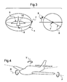
- Figure 3 illustrates an axis definition of a spatial attitude indicator according to the invention.
- the reference symbol 5 is fixed to the sphere 4 by means of two axes 7 and 8.
- the axis 7 which corresponds to an axis perpendicular to normal acceleration and to a vehicle's forward direction F is fixed to its relative position to sphere 4.
- the axis 8 is fixed in alignment parallel to the vehicle's forward direction and in the midpoint of axis 7.
- the axis 8 can rotate around the axis 8 at said midpoint.
- the reference symbol 5 is fixed to both axes 7 and 8 such that its centre of rotation is located in the midpoint of axis 7.
- the depiction of the forward direction F is fixed and aligned to the axis 8 and can freely rotate around axis 7.
- An inclination 9 of axis 8, and thus of the reference symbol 5, is proportional to the inclination of the vehicle around the pitch axis as defined in figure 4 (axis P).
- the rotation of the reference symbol 6 around the axis 8 is proportional to the roll angle of the vehicle as defined in figure 4 .
- a scale 10 can be presented which is slaved to a magnetic compass N,W,S,E or to any other direction or orientation reference direction.
- a pointer 11 which can move planar or spatial dependent on the application, can be shown pointing to a currently selected heading or reference. Further navigation aids, e.g. heading bugs, can also be included into the presentation.
- the inclination of the indicator under which the indication is seen on the instrument display which is the orientation of the sphere on the screen shall be selected in a way that maximum spatial situation information can be achieved.
- all available techniques to depict 3D elements or objects on a 2D screen (flat screen), like e.g. rendering, shading etc, can be used for finding the best solution for each individual vehicle.
- a scale of the direction and/or orientation reference system shall be engraved as longitudinal markings 12 and lateral markings 13 into the surface of the reference sphere 4.
- the longitudinal markings are equidistant lines joining each pole of the sphere 4 and the lateral markings are equidistant and parallel lines which are orthogonal to the longitudinal markings 12.
- the pitch scale 4c as shown in figure 6 can either be static and be shown in any case or can be selectively hidden in order to de-clutter the presentation.
- the pitch scale 4c can e.g. be shown in the forward part of the sphere if the vehicle symbol 6 is below a certain value, in order to highlight the excessive attitude situation.
- Pitch scale markings 4d are preferably engraved on the pitch scale 4c as shown on figure 6 .
- the forward direction F is defined by the direction of the main movement of the vehicle, as selected by the manufacturer, or the direction in which the crew member in command is looking during normal flight attitude.
- forward is defined as looking from the screen surface into the equipment. Both directions must be aligned in order to use the proposed principle.
- a half circle 14 is shown ranging away from the viewer. It is depicting the forward half intersection line between the sphere 4 (or reference system) and a transparent or semi-transparent plane of orientation 15 of the reference symbol 5.
- the orientation plane 15 can be transparent and can have different colours, depending on the side on which the observer is looking at. The transparency will ensure that the half circle 14 can always be identified.
- the reference symbol 5 is driven by the relative position and attitude of the vehicle with reference to a defined inertial system, either earth surface bound or any other.
- the rotation of the reference symbol 5 is bound to independent axes.
- these axes presented in attitude indicators would be the roll and the pitch axes.
- the new indicator according to the invention would be measuring the angles around said axes and rotating the reference symbol 5 in a corresponding manner, while the roll axis 8 is always parallel to the forward direction.
- the reference symbol 5 virtual centre will always be at the same position.
- the crew member is steering the reference symbol 5 in a way the vehicle would be naturally steered in order to control its position and attitude.
- the reference source for rotation of the reference symbol 6 is an inertial reference system which can be defined by a local platform, e.g. an AHRS or by referring to a space based system, e.g. sun observation sensors.
- the pointer 11 or directional reference is subject to de-clutter in case of excessive attitudes which have to be defined and based on the characteristics of the vehicle.
- Figure 5 illustrates an artificial spatial attitude indicator according to the invention, comprising e.g. a localizer or a course indication 16.
- the course or localizer indication 16 (line/symbol) is illustrated on the equator of the sphere 4.
- a deviation 17 from the course or localizer indication 16, can then be shown by shading an area 18 between the desired track corresponding to the course indication 16 and the deviation 17.
- An indication 16 showing a course would be fixed to the selected course, hence the position of a course indication 16 is depending on the current orientation of the compass scale 10.
- An indication 16 showing a localizer is always attached to the forward direction and does depict the localizer deviation by shading an area 18 between the localizer indication 16 and the current deviation 18.
- the current deviation 15 of a localizer is determined as on conventional localizer instruments.
- the reference symbol 5 is always aligned to heading, i.e. the orientation of the vehicle with reference to magnetic north N.
- the compass rose, or equivalent is always aligned to the heading, i.e. compass orientation, of the vehicle. Hence the compass rose will move around the equator of sphere 4 in order to keep the alignment.
- a line shall be displayed to show the course/localizer direction, and a second line or the shaded area shall be shown in order to show the course deviation 17 indication.
- a localizer indication could be fixed to the forward middle part of the sphere 4. As a relative information between heading and desired track is not relevant for a localizer, as only a deviation from a guidance signal is shown and used for guidance, a CDI style depiction would be presented in a fixed position of the sphere 4.
- the CDI analogy indication is set up by using localizer indication 16 in fixed forward position and placing symbol 18 depending on the deviation from the localizer.
- orientation symbol 6 can be used to create the CDI.
- Orientation symbol 6 can be created by two parts, which are both aligned to reference symbol 5 as defined, where one part is used as desired track line the other part as deviation.
- a glide-slope indication or any equivalent means can be introduced in a similar way.
- navigation information shall be de-cluttered as soon as a defined excessive attitude is reached or exceeded.
- an automatic reduction of the presented information reduces the crew's workload and supports to get the attention back to the main indications.
- the figures 7a, 7b and 7c show a few possible positions of the orientation plane 15.
- the aircraft or vehicle has a normal attitude.
- the orientation plane 15 extends along the equator of the sphere 4.
- the vehicle presents a left bank corresponding to an inclination (pivoting around the roll axis) with respect of the roll axis R.
- a bank angle ⁇ of the reference symbol 5 and the orientation plane 15 with respect of the half circle 14 is therefore shown on figure 7b .
- the vehicle presents a pitch up inclination (pivoting around the pitch axis) corresponding to an inclination with respect of the pitch axis P.
- a pitch angle ⁇ of the reference symbol 5 and the orientation plane 15 with respect of the half circle 14 is therefore shown on figure 7c .
- the method of presenting attitude and heading information of a vehicle, on a display to a viewer inside the given vehicle comprises the steps of:
- the method according to the invention consists of using roll and pitch data for the attitude information.
- the method according to the invention consists of using also yaw data for the attitude information.
- the method according to the invention consists of:
- the method according to the invention consists of:
- the method according to the invention consists of moving the orientation plane 15 within the sphere in order to display the angle between the straight forward direction of the vehicle and a longitudinal marking 12 of the sphere 4. This corresponds to the yaw information.
- the method according to the invention consists of using for the reference symbol 5 an additional half sphere placed inside the sphere 4 and whose plane surface constitutes the orientation plane 15 comprising a vehicle representation.
- the method according to the invention consists of depicting a deviation from a desired track by shading an area 18 of the sphere 4, ranging away from the viewer, lying between a first longitudinal marking 12 corresponding to the actual track or zero direction and a second longitudinal marking 12 which corresponds to the desired track.
- the method according to the invention consists of depicting the sphere combined with steering information of the vehicle with respect of power information or other flight information of the vehicle. For instance, alongside the sphere 4, steering information with respect of power settings can be projected. It is possible to provide information about the necessary pitch and roll attitude to achieve a certain performance, e.g. climb with a defined ROC, level flight at a defined speed.
- the method according to the invention consists of switching manually or automatically from one to another of the depicted 3D elements viewing mode and information to a conventional 2D artificial horizon representation or standard 2D projection mode.
- the method according to the invention is carried out on a helicopter.
- Other type or aircrafts for instance fixed wings aircrafts, or spacecrafts, can also be steered with the help of the method according to the invention.
Abstract
- using a 2D display,
- using data provided by an inertial reference system,
- using a computer and graphical software for treating the data and defining graphical elements,
- depicting the graphical elements in 3D on the 2D display,
- and presenting the attitude and heading information on the 2D display by associating them to at least one graphical element.
Description
- The present invention relates to the general technical field of equipments used for flight guidance.
- The invention concerns more particularly a method for presenting attitude and heading information of a vehicle and artificial spatial attitude and heading indicators or instruments of vehicle.
- The term "vehicle" encompasses any type of aircrafts or spacecrafts.
- Different terms are used and for which the meaning is given by the definitions as follows:
- 2D: two dimensional,
- 3D: three dimensional,
- AHRS: attitude and heading reference system,
- CDI: Course Deviation Indicator
- EFIS: electronic flight information system,
- Heading: direction with reference to the magnetic field of earth, or with reference to any other horizontal information.
- IFR: Instrument Flight Rules,
- ROC: rate of climb.
- The pilot of an aircraft needs in general many aircraft and environment data for taking the optimal decisions during his flight, especially in emergency situations. Among these data, there is for instance the aircraft attitude information such as pitch and roll information.
- During the flight, the pilot should be aware of the instantaneous situation, such as e.g. altitude, airspeed and attitude under IFR conditions in order to determine the flight path and motion of the aircraft. The current state of the art equipments, however, cannot provide such instantaneous situation awareness. These known equipments, either providing inside-out or outside-in view, do not present the vehicle or aircraft's attitude in relation to the reference system, e.g. the orientation compared to the earth's surface.
- It can occur that the pilot can see only the earth or only a blue sky in his primary flight display of the known equipments and that he cannot easily know in which direction he should steer to get a normal level of flight attitude.
- By inside-out, one should understand that the aircraft symbol remains fixed while the background and horizon indicators move to indicate the aircraft attitude.
- By outside-in, one should understand that the aircraft symbol moves in the same apparent direction as the aircraft is actually moving.
- It is known to present horizontal information on a flat depiction in either inside-out or outside-in view. Both solutions lack a certain spatial orientation information as soon as the depiction limits are reached.
- The depiction limits addressed with this invention are the fact that the projection of the 3D spatial situation on a flat area does reduce the information transmitted. The usual model to depict an attitude is to use a cylinder, sphere or similar which is divided into two equal parts. Both parts are painted in different colours, normally blue for the sky (upwards) and brown for the earth surface (downwards). When projecting this model onto the 2D screen area and taking into account that the object is not fully visible, but only a small viewport as selected by the designer of the artificial horizon, there are possible modes in which only one part of the model sphere is projected.
- Those modes are lacking any information about the actual attitude or directions to correct the attitude. Means to overcome such situations have been developed in the past and lead to the introduction of flight director bars in the attitude indication.
- A typical and known presentation of an artificial horizon will be for example an inside-out view projected onto a 2D (two dimensional) screen picture. The attitude indication provided by an inside-out view on a known artificial horizon has led to some abnormal situations and was so not considered as satisfactory.
- Another kind of presentation currently used is an outside-in view, still projected on a 2D presentation.
- The presentation of the 3D spatial orientation on a 2D projection lacks information as soon as the projection is full by either the sky or the earth. In such a case markings or other clues need to be added in order to provide the necessary orientation information for undertaking corrections. In high workload situations, such markings can easily be neglected by the crew as they might be occupied by other distraction coming from the aircraft or from the environment.
- None of the above mentioned known indicators (inside-out or outside-in) are is therefore satisfactory. Additional guidance information needs always to be introduced which is conclusive only after intensive training of the pilot.
- An exemplary embodiment of a known attitude indicator is described in document
US 4 563 742 , which discloses an attitude indicator combining the best features of both the inside-out and outside-in viewing modes. The aircraft symbol is positioned in accordance with the pitch of said aircraft and a horizon indicator is also positioned in accordance with the pitch of said aircraft. In this embodiment, there is a need of the two information elements, the pitch, which renders such a solution relatively complex. The drawback for this solution is the overlay of two moving elements, one representing the horizon, in order to provide the expected inside-out view and a movement of the aircraft pictorial, which will move in the opposite direction of the horizon. In addition, this principle is limited in feasibility to attitude situations which are not adverse, like e.g. nose fully up. Additionally the overlay of a moving object over the attitude presentation can result in misleading interpretation in case of high workload situations. The presented solution lacks also the immediate information about the corrective actions to be taken in adverse situations. - Another exemplary embodiment of known attitude indicator is described in document
US 5 181 028 , which discloses an attitude indicator with the use of shutter goggles and a fixed 3D aircraft presentation on a 3D display. The cost of such an instrument or indicator is therefore relatively high. This solution lacks simplicity as it requires several hardware items to work together. With malfunction of the googles, which might not be feasible to be used during night flights, the crew is back to the classical presentation of attitude. Additionally them usage of googles impairs problems and incompatibilities with other indicators in the cockpit, as it will filter wavelength or polarization, independently from the source of information, and has to be applied for usage with elements based on polarization, i.e. LCD displays. - Consequently the objective of the present invention is to remedy the aforementioned disadvantages and propose a new, reliable and improved spatial attitude indicator.
- The object of the invention is also to provide a new spatial attitude indicator which indicates the absolute spatial attitude in such a way that the pilot knows always in which direction he has to steer to reach a safe flight attitude.
- The objectives of the invention are achieved by a method of presenting attitude and heading information of a vehicle, on a display to a viewer inside the given vehicle, comprising the steps of:
- using a 2D display,
- using data provided by an inertial reference system,
- using a computer and graphical software for treating the data and defining 3D graphical elements,
- depicting the 3D graphical elements on the 2D display,
- and presenting the attitude and heading information on the 2D display by associating them to at least one graphical element.
- By way of example, the method according to the invention consists of using roll and pitch data for the attitude information.
- By way of example, the method according to the invention consists of using also yaw data for the attitude information.
- By way of example, the method according to the invention consists of:
- depicting a first graphical element as a transparent sphere representing a inertial reference system with respect of the inertial reference for the movement of the vehicle, the sphere comprising longitudinal and lateral markings on its surface representing direction and orientation references, an upper half sphere representing the sky and the lower half sphere representing the ground,
- projecting movable heading information in response to variations in heading on the surface of the sphere,
- using a second graphical element which is fixed with respect of the vehicle, representing a 3D reference symbol of the vehicle and/or its main axes and/or its orientation plane,
- placing the reference symbol in the sphere,
- moving the reference symbol inside the fixed sphere with regard to the vehicle's movement in the inertial reference system,
- and depicting the graphical elements in a vehicle external observer viewing mode.
- The depicted sphere is fixed to the instrument display but can allow adjustments by the crew if necessary. Those adjustments can include, but are not limited to, certain movement in of the sphere's projection on the 2D screen of the instrument display, zooming or information de-cluttering.
- By way of example, the method according to the invention consists of:
- depicting at the equator of the sphere a half circle ranging away from the viewer highlighting the artificial horizon on the surface of the sphere,
- aligning the half circle to the reference symbol of the vehicle,
- and keeping the sphere and its surface elements fixed to the inertial reference system while moving the reference symbol within the sphere in order to display the angles between the orientation plane and the half circle.
- By way of example, the method according to the invention consists of displaying a current heading aligned to the straight forward direction of the vehicle and to place longitudinal markings of the sphere.
- By way of example, the method according to the invention consists of using for the reference symbol an additional half sphere placed inside the sphere and whose spherical part is moving and whose plane surface constitutes the orientation plane comprising a vehicle representation.
- By way of example, the method according to the invention consists of depicting a deviation from a course by shading an area of the sphere, ranging away from the viewer, lying between a longitudinal marking corresponding to the actual track and a longitudinal marking which corresponds to the selected course.
- By way of example, the method according to the invention consists of depicting the sphere combined with steering information of the vehicle with respect of power information or other flight information of the vehicle.
- By way of example, the method according to the invention consists of switching manually or automatically from one to another of the depicted 3D elements viewing mode and information to a conventional 2D artificial horizon representation or standard 2D projection mode.
- By way of example, the method according to the invention is carried out on a helicopter. Other type or aircrafts, for instance fixed wing aircrafts, or spacecrafts, can also be steered with the help of the method according to the invention.
- The objectives of the invention are also achieved with an artificial spatial attitude and heading indicator for a vehicle such as an aircraft or a spacecraft, comprising a 2D display, an inertial reference system, a computer and a graphical software for treating the data provided by the inertial reference system and for preparing the elements and information to be displayed, characterized in that the graphical software is a part of an avionic system for carrying out the steps of the above mentioned method.
- An advantage of the method according to the invention lies in the direct spatial presentation of the vehicle's attitude while the crew member is still steering the inside-out part of the indication. It is a more intuitive presentation and supports the spatial orientation gathering especially in case of distraction or high workload, as the crew member will be in a third party observer position, which supports getting back the necessary overview for an abnormal situation.
- An advantage of the artificial spatial attitude indicator conforming to the invention, resides in that it provides the pilot with reliable attitude information which do not require too many attention and/or expertise from the pilot. It will so enhance the awareness situation, especially in high workload situations. The safety can so be improved especially in adverse environment.
- Another advantage of the spatial attitude indicator according to the invention lies in its use on any type of aircrafts, such as helicopters or fixed wings aircrafts.
- Another advantage of the spatial attitude indicator according to the invention and of the method according to the invention, lies in the fact that there is no need to use any additional devices such as lenses or other special means for depicting a 3D representation of some elements on the 2D display.
- The invention and its advantages will appear with greater detail in conjunction with the description which follows with execution and implementation examples, given as illustration and without limitation, with reference to the attached figures in which:
-
figure 1 illustrates an example of presentation of an known artificial spatial attitude indicator according to the state of the art, -
figure 2 illustrates an example of presentation of an artificial spatial attitude indicator according to the invention, -
figure 3 illustrates an axis definition of an artificial spatial attitude indicator according to the invention, -
figure 4 illustrates a typical axis definition of a vehicle such as an aircraft, -
figure 5 illustrates an artificial spatial attitude indicator according to the invention, comprising a localizer indication, -
figure 6 illustrates an optional pitch scaling on a reference sphere of an embodiment of the artificial spatial attitude indicator according to the invention, - and
figures 7a, 7b, 7c illustrate different attitudes as they would be indicated by an embodiment of the artificial spatial attitude indicator according to the invention. - The identical structural and functional elements, which are shown in several different figures or illustrations, are given one single numeric or alphanumeric reference.
- In
figure 1 , an artificial spatial attitude indicator 1 of the state of the art comprises a fixed aircraft symbol 2 ahorizon 3. As depicted infigure 1 , the available field of view is approximately +/-20°. This leads to a loss of information as soon as the flight attitude is above or below this value. Especially if this situation is combined with a roll motion, a spatial disorientation can easily occur. Additional guidance needs to be introduced to overcome this problem. This would require intensive training for crew to undertake quickly the necessary flight corrections. - According to the invention, the artificial spatial attitude and heading indicator for a vehicle such as an aircraft or a spacecraft, comprising a 2D display, an inertial reference system, a computer and a graphical software or a graphic algorithm for treating the data provided by the inertial reference system and for preparing the elements and information to be displayed. The graphical software is a part of an avionic system for carrying out the steps of the above mentioned method.
- The invention is so based on an implementation of an algorithm into a computer with an attached 2D display. Such an implementation can be done either by software or by specific design logic circuits, e.g. FPGA arrays.
-
Figure 2 illustrates an exemplary presentation of an artificial spatial attitude indicator according to the invention. - The indicator is based on a
sphere 4 defining a reference system for the purpose of guidance. This reference system can include any useful or supportive information drawn to its surface. This information can be moving on the surface of the sphere as appropriate. The reference system is fixed the vehicle so that it will not move relative to the crew. - The reference system, i.e. the
sphere 4 is divided into twohalf spheres upper half sphere 4a is depicting the direction for the sky or towards a defined upwards reference or axis if applied to a spacecraft. However, the actual axes of the reference system (sphere 4) are not aligned to the actual attitude of the vehicle in relation to the real-world references. The orientation of thesphere 4 which is used as reference is fixed to the display, and therefore to the vehicle. The object moved is the depiction of the vehicle. - The
lower half sphere 4b is depicting the direction towards the earth or towards a defined downward direction if applied to a spacecraft. - A
reference symbol 5, e.g. a half sphere inside thesphere 4 or any other depiction of a vehicle, which should preferably be a 3D model of the vehicle itself, is placed inside the sphere 4 (reference system). Anorientation symbol 6 of any kind, fixed to thereference symbol 5, is given to indicate the main axes of the vehicle and especially the straight forward movement direction of the vehicle. - The
reference symbol 5 is aligned to thesphere 4 as the actual vehicle is aligned to the real world reference system. This is achieved by transforming an attitude determined by a vehicle based reference system in the coordinates of the spatial attitude indicator. - For instance, a level attitude is defined when the roll and pitch axis of the vehicle are located in the plan defined by the separation line between both
spheres figure 7a . -
Figure 3 illustrates an axis definition of a spatial attitude indicator according to the invention. - The
reference symbol 5 is fixed to thesphere 4 by means of twoaxes axis 7 which corresponds to an axis perpendicular to normal acceleration and to a vehicle's forward direction F is fixed to its relative position tosphere 4. Theaxis 8 is fixed in alignment parallel to the vehicle's forward direction and in the midpoint ofaxis 7. Theaxis 8 can rotate around theaxis 8 at said midpoint. - The
reference symbol 5 is fixed to bothaxes axis 7. The depiction of the forward direction F is fixed and aligned to theaxis 8 and can freely rotate aroundaxis 7. - An
inclination 9 ofaxis 8, and thus of thereference symbol 5, is proportional to the inclination of the vehicle around the pitch axis as defined infigure 4 (axis P). The rotation of thereference symbol 6 around theaxis 8 is proportional to the roll angle of the vehicle as defined infigure 4 . - Alongside an equator of the
sphere 4, ascale 10 can be presented which is slaved to a magnetic compass N,W,S,E or to any other direction or orientation reference direction. Apointer 11, which can move planar or spatial dependent on the application, can be shown pointing to a currently selected heading or reference. Further navigation aids, e.g. heading bugs, can also be included into the presentation. - The inclination of the indicator under which the indication is seen on the instrument display, which is the orientation of the sphere on the screen shall be selected in a way that maximum spatial situation information can be achieved. In order to achieve this, all available techniques to depict 3D elements or objects on a 2D screen (flat screen), like e.g. rendering, shading etc, can be used for finding the best solution for each individual vehicle.
- A scale of the direction and/or orientation reference system shall be engraved as
longitudinal markings 12 andlateral markings 13 into the surface of thereference sphere 4. The longitudinal markings are equidistant lines joining each pole of thesphere 4 and the lateral markings are equidistant and parallel lines which are orthogonal to thelongitudinal markings 12. - The
pitch scale 4c as shown infigure 6 can either be static and be shown in any case or can be selectively hidden in order to de-clutter the presentation. Thepitch scale 4c can e.g. be shown in the forward part of the sphere if thevehicle symbol 6 is below a certain value, in order to highlight the excessive attitude situation.Pitch scale markings 4d are preferably engraved on thepitch scale 4c as shown onfigure 6 . - The forward direction F is defined by the direction of the main movement of the vehicle, as selected by the manufacturer, or the direction in which the crew member in command is looking during normal flight attitude. On the indicator screen, forward is defined as looking from the screen surface into the equipment. Both directions must be aligned in order to use the proposed principle.
- At the equator of the
sphere 4, ahalf circle 14 is shown ranging away from the viewer. It is depicting the forward half intersection line between the sphere 4 (or reference system) and a transparent or semi-transparent plane oforientation 15 of thereference symbol 5. - The
orientation plane 15 can be transparent and can have different colours, depending on the side on which the observer is looking at. The transparency will ensure that thehalf circle 14 can always be identified. - The
reference symbol 5 is driven by the relative position and attitude of the vehicle with reference to a defined inertial system, either earth surface bound or any other. The rotation of thereference symbol 5 is bound to independent axes. For example these axes presented in attitude indicators would be the roll and the pitch axes. The new indicator according to the invention would be measuring the angles around said axes and rotating thereference symbol 5 in a corresponding manner, while theroll axis 8 is always parallel to the forward direction. - The
reference symbol 5 virtual centre will always be at the same position. - A movement around a third axis, depicted in
figure 4 as the yaw axis, shall be presented only as a movement of a radial scale located around the circumference of thesphere 4. This will reduce the complexity of the information. - The crew member is steering the
reference symbol 5 in a way the vehicle would be naturally steered in order to control its position and attitude. - The reference source for rotation of the
reference symbol 6 is an inertial reference system which can be defined by a local platform, e.g. an AHRS or by referring to a space based system, e.g. sun observation sensors. - The
pointer 11 or directional reference is subject to de-clutter in case of excessive attitudes which have to be defined and based on the characteristics of the vehicle. -
Figure 5 illustrates an artificial spatial attitude indicator according to the invention, comprising e.g. a localizer or acourse indication 16. - According to the invention, the course or localizer indication 16 (line/symbol) is illustrated on the equator of the
sphere 4. Adeviation 17 from the course orlocalizer indication 16, can then be shown by shading anarea 18 between the desired track corresponding to thecourse indication 16 and thedeviation 17. - An
indication 16 showing a course would be fixed to the selected course, hence the position of acourse indication 16 is depending on the current orientation of thecompass scale 10. - An
indication 16 showing a localizer is always attached to the forward direction and does depict the localizer deviation by shading anarea 18 between thelocalizer indication 16 and thecurrent deviation 18. Thecurrent deviation 15 of a localizer is determined as on conventional localizer instruments. - The
reference symbol 5 is always aligned to heading, i.e. the orientation of the vehicle with reference to magnetic north N. The compass rose, or equivalent, is always aligned to the heading, i.e. compass orientation, of the vehicle. Hence the compass rose will move around the equator ofsphere 4 in order to keep the alignment. On the scale on thesphere 4, a line shall be displayed to show the course/localizer direction, and a second line or the shaded area shall be shown in order to show thecourse deviation 17 indication. - A localizer indication could be fixed to the forward middle part of the
sphere 4. As a relative information between heading and desired track is not relevant for a localizer, as only a deviation from a guidance signal is shown and used for guidance, a CDI style depiction would be presented in a fixed position of thesphere 4. The CDI analogy indication is set up by usinglocalizer indication 16 in fixed forward position and placingsymbol 18 depending on the deviation from the localizer. - Alternatively
orientation symbol 6 can be used to create the CDI.Orientation symbol 6 can be created by two parts, which are both aligned toreference symbol 5 as defined, where one part is used as desired track line the other part as deviation. - A glide-slope indication or any equivalent means can be introduced in a similar way.
- In general, navigation information shall be de-cluttered as soon as a defined excessive attitude is reached or exceeded. In this case an automatic reduction of the presented information reduces the crew's workload and supports to get the attention back to the main indications.
- The
figures 7a, 7b and 7c show a few possible positions of theorientation plane 15. - In
figure 7a , the aircraft or vehicle has a normal attitude. Theorientation plane 15 extends along the equator of thesphere 4. - In
figure 7b , the vehicle presents a left bank corresponding to an inclination (pivoting around the roll axis) with respect of the roll axis R. A bank angle α of thereference symbol 5 and theorientation plane 15 with respect of thehalf circle 14 is therefore shown onfigure 7b . - In
figure 7c , the vehicle presents a pitch up inclination (pivoting around the pitch axis) corresponding to an inclination with respect of the pitch axis P. A pitch angle ϕ of thereference symbol 5 and theorientation plane 15 with respect of thehalf circle 14 is therefore shown onfigure 7c . - According to the invention, the method of presenting attitude and heading information of a vehicle, on a display to a viewer inside the given vehicle, comprises the steps of:
- using a 2D display,
- using data provided by an inertial reference system,
- using a computer and graphical software/algorithm for treating the data and defining graphical elements,
- depicting the graphical elements in 3D on the 2D display,
- and presenting the attitude and heading information on the 2D display by associating them to at least one graphical element.
- By way of example, the method according to the invention consists of using roll and pitch data for the attitude information.
- By way of another example, the method according to the invention consists of using also yaw data for the attitude information.
- By way of preferred example, the method according to the invention consists of:
- depicting a first graphical element as the
transparent sphere 4 representing an inertial reference system with respect of the vehicle, thesphere 4 comprising longitudinal 12 andlateral markings 13 on its surface, representing direction and orientation references, theupper half sphere 4a representing the sky and thelower half sphere 4b representing the ground, - projecting movable attitude and heading information in response to variations in attitude or heading on the surface of the
sphere 4, - using a second graphical element which is fixed with respect of the vehicle, representing a 3D reference symbol of the vehicle and/or its main axes and/or its
orientation plane 15, - placing the
reference symbol 5 in thesphere 4, - and depicting the graphical elements in a vehicle external observer viewing mode.
- By way of example, the method according to the invention consists of:
- depicting at the equator of the
sphere 4 thehalf circle 14 ranging away from the viewer representing an artificial horizon, - and keeping the
reference symbol 5 in the straight forward direction of the vehicle while moving theorientation plane 15 and thereference symbol 5 within thesphere 4 in order to display the angles between both and thehalf circle 14. This corresponds to the roll and pitch information. - By way of example, the method according to the invention consists of moving the
orientation plane 15 within the sphere in order to display the angle between the straight forward direction of the vehicle and alongitudinal marking 12 of thesphere 4. This corresponds to the yaw information. - By way of example, the method according to the invention consists of using for the
reference symbol 5 an additional half sphere placed inside thesphere 4 and whose plane surface constitutes theorientation plane 15 comprising a vehicle representation. - By way of example, the method according to the invention consists of depicting a deviation from a desired track by shading an
area 18 of thesphere 4, ranging away from the viewer, lying between a firstlongitudinal marking 12 corresponding to the actual track or zero direction and a second longitudinal marking 12 which corresponds to the desired track. - By way of example, the method according to the invention consists of depicting the sphere combined with steering information of the vehicle with respect of power information or other flight information of the vehicle. For instance, alongside the
sphere 4, steering information with respect of power settings can be projected. It is possible to provide information about the necessary pitch and roll attitude to achieve a certain performance, e.g. climb with a defined ROC, level flight at a defined speed. - By way of example, the method according to the invention consists of switching manually or automatically from one to another of the depicted 3D elements viewing mode and information to a conventional 2D artificial horizon representation or standard 2D projection mode.
- By way of example, the method according to the invention is carried out on a helicopter. Other type or aircrafts, for instance fixed wings aircrafts, or spacecrafts, can also be steered with the help of the method according to the invention.
- Unsurprisingly, the present invention is subject to several variations in terms of its implementation. Although several execution and implementation modes have been described, it is clear that identifying all possible modes exhaustively is inconceivable. It is, of course, possible to replace any feature or step described above with an equivalent feature or step and still remain within the scope of the present invention.
Claims (12)
- Method of presenting attitude and heading information of a vehicle, on a display to a viewer inside the given vehicle, comprising the steps of:- using a 2D display,- using data provided by an inertial reference system,- using a computer and graphical software for treating the data and defining 3D graphical elements,- depicting the 3D graphical elements on the 2D display,- and presenting the attitude and heading information on the 2D display by associating them to at least one 3D graphical element.
- Method according to claim 1,
characterized in that it consists of using roll and pitch data for the attitude information. - Method according to claim 2,
characterized it consists of using also yaw data for the attitude information. - Method according to any one of claims 1 to 3, characterized in that it consists of:- depicting a first graphical element as a transparent sphere representing a fixed reference system with respect of the inertial reference for the movement of the vehicle, the sphere comprising longitudinal and lateral markings on its surface representing direction and orientation references, an upper half sphere representing the sky and the lower half sphere representing the ground,- projecting movable heading information in response to variations in heading on the surface of the sphere,- using a second graphical element which is fixed with respect of the vehicle, representing a 3D reference symbol of the vehicle and/or its main axes and/or its orientation plane,- placing the reference symbol in the sphere,- moving the reference symbol inside the fixed sphere with regard to the vehicle's movement in the inertial reference system,- and depicting the graphical elements in a vehicle external observer viewing mode.
- Method according to claim 4,
characterized in that it consists of:- depicting at the equator of the sphere a half circle ranging away from the viewer representing an artificial horizon,- and keeping the sphere and its surface elements fixed to the inertial reference system while moving the reference symbol within the sphere in order to display the angles between the orientation plane and the half circle. - Method according to claim 5,
characterized in that it consists of displaying a current heading aligned to the straight forward direction of the vehicle and to place longitudinal markings of the sphere. - Method according to any one of claims 4 to 6,
characterized in that it consists of using for the reference symbol an additional half sphere placed inside the sphere and whose plane surface constitutes the orientation plane comprising a vehicle representation. - Method according to any one of claims 4 to 7,
characterized in that it consists of depicting a deviation from a course by shading an area of the sphere, ranging away from the viewer, lying between a longitudinal marking corresponding to the actual track and a longitudinal marking corresponding the selected course. - Method according to any one of claims 4 to 8,
characterized in that it consists of depicting the sphere combined with steering information of the vehicle with respect of power information or other flight information of the vehicle. - Method according to any one of claims 1 to 9,
characterized in that it consists of switching manually or automatically from one to another of the depicted 3D elements viewing mode and information to a conventional 2D artificial horizon representation or standard 2D projection mode. - Method according to any one of claims 1 to 10,
characterized in that it is carried out on a helicopter. - Artificial spatial attitude and heading indicator for a vehicle such as an aircraft or a spacecraft, comprising a 2D display, an inertial reference system, a computer and a graphical software for treating the data provided by the inertial reference system and for preparing the elements and information to be displayed,
characterized in that the graphical software is a part of an avionic system for carrying out the steps of the method according to any one of the claims 1 to 11.
Priority Applications (2)
| Application Number | Priority Date | Filing Date | Title |
|---|---|---|---|
| EP10400064.1A EP2466264B1 (en) | 2010-12-17 | 2010-12-17 | Method for presenting spatial attitude and heading information of a vehicle |
| US13/314,276 US8803709B2 (en) | 2010-12-17 | 2011-12-08 | Method for presenting spatial attitude and heading information of a vehicle |
Applications Claiming Priority (1)
| Application Number | Priority Date | Filing Date | Title |
|---|---|---|---|
| EP10400064.1A EP2466264B1 (en) | 2010-12-17 | 2010-12-17 | Method for presenting spatial attitude and heading information of a vehicle |
Publications (2)
| Publication Number | Publication Date |
|---|---|
| EP2466264A1 true EP2466264A1 (en) | 2012-06-20 |
| EP2466264B1 EP2466264B1 (en) | 2014-02-12 |
Family
ID=43971119
Family Applications (1)
| Application Number | Title | Priority Date | Filing Date |
|---|---|---|---|
| EP10400064.1A Not-in-force EP2466264B1 (en) | 2010-12-17 | 2010-12-17 | Method for presenting spatial attitude and heading information of a vehicle |
Country Status (2)
| Country | Link |
|---|---|
| US (1) | US8803709B2 (en) |
| EP (1) | EP2466264B1 (en) |
Cited By (1)
| Publication number | Priority date | Publication date | Assignee | Title |
|---|---|---|---|---|
| EP2757350A1 (en) * | 2013-01-18 | 2014-07-23 | EADS Deutschland GmbH | Display of aircraft attitude |
Families Citing this family (7)
| Publication number | Priority date | Publication date | Assignee | Title |
|---|---|---|---|---|
| US20130260879A1 (en) | 2002-10-09 | 2013-10-03 | Michael W. Saunders | System and Method for Connecting Gaming Devices to a Network for Remote Play |
| US20130035166A1 (en) * | 2011-08-01 | 2013-02-07 | Hess Chuck L | Method of operating an online game using a globe-shaped controller |
| US9221552B2 (en) | 2012-06-29 | 2015-12-29 | Honeywell International Inc. | Aircraft systems and methods for attitude recovery |
| US9128113B2 (en) | 2014-01-27 | 2015-09-08 | Nissan North America, Inc. | Vehicle orientation indicator |
| US9889947B1 (en) * | 2016-10-13 | 2018-02-13 | Honeywell International Inc. | System and method for generating and displaying an aircraft orientation cue |
| CN113298041A (en) * | 2021-06-21 | 2021-08-24 | 黑芝麻智能科技(上海)有限公司 | Method and system for calibrating driver distraction reference direction |
| FR3128529B1 (en) * | 2021-10-22 | 2024-03-15 | Airbus Helicopters | Method and system for assisting in piloting an aircraft in flight |
Citations (3)
| Publication number | Priority date | Publication date | Assignee | Title |
|---|---|---|---|---|
| US4563742A (en) | 1983-09-26 | 1986-01-07 | Rockwell International Corporation | Combined motion cueing attitude indicator |
| EP0383083A1 (en) * | 1989-02-11 | 1990-08-22 | Messerschmitt-Bölkow-Blohm Gesellschaft mit beschränkter Haftung | Aircraft display instrument |
| US5181028A (en) | 1990-06-20 | 1993-01-19 | Rockwell International Corporation | 3D stereo integrated attitude director and horizontal situation indicator apparatus |
Family Cites Families (11)
| Publication number | Priority date | Publication date | Assignee | Title |
|---|---|---|---|---|
| US3967236A (en) * | 1974-03-29 | 1976-06-29 | Sperry Rand Corporation | Command cue for a flight director instrument |
| US4326189A (en) * | 1979-04-23 | 1982-04-20 | Crane Carl J | Aircraft control/guidance display and mechanism for enroute and landing utility |
| SE447234B (en) * | 1983-01-07 | 1986-11-03 | Saab Scania Ab | FERDLEGESINDIKATOR |
| US5095746A (en) | 1988-01-07 | 1992-03-17 | Stanis John W | Aircraft banking angle indicator |
| SG120849A1 (en) | 2000-06-02 | 2006-04-26 | Singapore Tech Aerospace Ltd | A method of forming a virtual three-dimensional radar display |
| US7286911B2 (en) | 2003-12-01 | 2007-10-23 | Kane Richard L | Aircraft pilot assistance system and method |
| US7908041B2 (en) | 2004-04-29 | 2011-03-15 | Munro & Associates, Inc. | Self-leveling laser horizon for navigation guidance |
| US7224311B2 (en) * | 2004-08-27 | 2007-05-29 | Analytical Graphics, Inc. | System and method for visualization of attitude and attitude/position dependent data |
| US20090283027A1 (en) | 2008-05-19 | 2009-11-19 | Melinda Marie Cameron | Global gravitational horizon |
| US8344911B1 (en) * | 2010-02-18 | 2013-01-01 | Rockwell Collins, Inc. | System, module, and method for generating non-linearly spaced graduations for a symbolic linear scale |
| US9494447B2 (en) * | 2010-07-28 | 2016-11-15 | Honeywell International Inc. | Methods and systems for attitude differentiation in enhanced vision images |
-
2010
- 2010-12-17 EP EP10400064.1A patent/EP2466264B1/en not_active Not-in-force
-
2011
- 2011-12-08 US US13/314,276 patent/US8803709B2/en not_active Expired - Fee Related
Patent Citations (3)
| Publication number | Priority date | Publication date | Assignee | Title |
|---|---|---|---|---|
| US4563742A (en) | 1983-09-26 | 1986-01-07 | Rockwell International Corporation | Combined motion cueing attitude indicator |
| EP0383083A1 (en) * | 1989-02-11 | 1990-08-22 | Messerschmitt-Bölkow-Blohm Gesellschaft mit beschränkter Haftung | Aircraft display instrument |
| US5181028A (en) | 1990-06-20 | 1993-01-19 | Rockwell International Corporation | 3D stereo integrated attitude director and horizontal situation indicator apparatus |
Cited By (4)
| Publication number | Priority date | Publication date | Assignee | Title |
|---|---|---|---|---|
| EP2757350A1 (en) * | 2013-01-18 | 2014-07-23 | EADS Deutschland GmbH | Display of aircraft attitude |
| WO2014111251A3 (en) * | 2013-01-18 | 2014-09-12 | Eads Deutschland Gmbh | Display of aircraft attitude |
| RU2651621C2 (en) * | 2013-01-18 | 2018-04-23 | Эйрбас Дефенс Энд Спэйс Гмбх | Display of aircraft attitude |
| US9989378B2 (en) | 2013-01-18 | 2018-06-05 | Airbus Defence and Space GmbH | Display of aircraft altitude |
Also Published As
| Publication number | Publication date |
|---|---|
| US20120154178A1 (en) | 2012-06-21 |
| US8803709B2 (en) | 2014-08-12 |
| EP2466264B1 (en) | 2014-02-12 |
Similar Documents
| Publication | Publication Date | Title |
|---|---|---|
| US8803709B2 (en) | Method for presenting spatial attitude and heading information of a vehicle | |
| US5072218A (en) | Contact-analog headup display method and apparatus | |
| CN105139451B (en) | A kind of Synthetic vision based on HUD guides display system | |
| US10678238B2 (en) | Modified-reality device and method for operating a modified-reality device | |
| EP2101155B1 (en) | Method and apparatus for displaying flight path information in rotorcraft | |
| US8170729B2 (en) | Method and system for operating a display device on-board an aircraft | |
| EP2360452A2 (en) | Methods and systems for displaying a symbol representative of an aircraft in flight | |
| US9581465B2 (en) | Apparatus and method for displaying a synthetic vision system view direction | |
| US9244649B2 (en) | Piloting assistance system and an aircraft | |
| US20170053453A1 (en) | Avionic system comprising means for designating and marking land | |
| CA2682530C (en) | Self-orienting reticle | |
| US20190056901A1 (en) | Aircraft systems and methods for unusual attitude recovery | |
| EP3301400A1 (en) | Aircraft display systems and methods for generating horizontal situation indicator graphics with enhanced symbology | |
| EP2846134B1 (en) | Helicopter system and method for integrating collective flight director cues | |
| US5181028A (en) | 3D stereo integrated attitude director and horizontal situation indicator apparatus | |
| JPH02145914A (en) | Display device for aircraft | |
| US20170160794A1 (en) | System comprising a headset equipped with a display device and documentation display and management means | |
| US20140055323A1 (en) | Visualisation system, notably for an aircraft, with a transparent screen and with peripheral symbology | |
| RU2207514C1 (en) | Flight director | |
| US20170168560A1 (en) | Method of displaying an "attitude director indicator" in a head viewing system for aircraft | |
| Döhler et al. | Virtual aircraft-fixed cockpit instruments | |
| US20120004792A1 (en) | Weber-box, an aviation display device to support spatial awareness | |
| US11047707B2 (en) | Visualization method of the attitude of an aircraft, associated computer program product and visualization system | |
| Lueken et al. | Virtual cockpit instrumentation using helmet mounted display technology | |
| de Haag | EE6900 Flight Management Systems |
Legal Events
| Date | Code | Title | Description |
|---|---|---|---|
| PUAI | Public reference made under article 153(3) epc to a published international application that has entered the european phase |
Free format text: ORIGINAL CODE: 0009012 |
|
| AK | Designated contracting states |
Kind code of ref document: A1 Designated state(s): AL AT BE BG CH CY CZ DE DK EE ES FI FR GB GR HR HU IE IS IT LI LT LU LV MC MK MT NL NO PL PT RO RS SE SI SK SM TR |
|
| AX | Request for extension of the european patent |
Extension state: BA ME |
|
| 17P | Request for examination filed |
Effective date: 20120605 |
|
| RIC1 | Information provided on ipc code assigned before grant |
Ipc: G01C 23/00 20060101AFI20130704BHEP |
|
| GRAP | Despatch of communication of intention to grant a patent |
Free format text: ORIGINAL CODE: EPIDOSNIGR1 |
|
| INTG | Intention to grant announced |
Effective date: 20130911 |
|
| GRAS | Grant fee paid |
Free format text: ORIGINAL CODE: EPIDOSNIGR3 |
|
| GRAA | (expected) grant |
Free format text: ORIGINAL CODE: 0009210 |
|
| AK | Designated contracting states |
Kind code of ref document: B1 Designated state(s): AL AT BE BG CH CY CZ DE DK EE ES FI FR GB GR HR HU IE IS IT LI LT LU LV MC MK MT NL NO PL PT RO RS SE SI SK SM TR |
|
| REG | Reference to a national code |
Ref country code: GB Ref legal event code: FG4D |
|
| REG | Reference to a national code |
Ref country code: CH Ref legal event code: EP |
|
| REG | Reference to a national code |
Ref country code: AT Ref legal event code: REF Ref document number: 652338 Country of ref document: AT Kind code of ref document: T Effective date: 20140215 |
|
| REG | Reference to a national code |
Ref country code: IE Ref legal event code: FG4D |
|
| REG | Reference to a national code |
Ref country code: DE Ref legal event code: R096 Ref document number: 602010013497 Country of ref document: DE Effective date: 20140327 |
|
| RAP2 | Party data changed (patent owner data changed or rights of a patent transferred) |
Owner name: AIRBUS HELICOPTERS DEUTSCHLAND GMBH |
|
| REG | Reference to a national code |
Ref country code: NL Ref legal event code: VDEP Effective date: 20140212 Ref country code: DE Ref legal event code: R081 Ref document number: 602010013497 Country of ref document: DE Owner name: AIRBUS HELICOPTERS DEUTSCHLAND GMBH, DE Free format text: FORMER OWNER: EUROCOPTER DEUTSCHLAND GMBH, 86609 DONAUWOERTH, DE Effective date: 20140508 |
|
| REG | Reference to a national code |
Ref country code: AT Ref legal event code: MK05 Ref document number: 652338 Country of ref document: AT Kind code of ref document: T Effective date: 20140212 |
|
| REG | Reference to a national code |
Ref country code: LT Ref legal event code: MG4D |
|
| PG25 | Lapsed in a contracting state [announced via postgrant information from national office to epo] |
Ref country code: NO Free format text: LAPSE BECAUSE OF FAILURE TO SUBMIT A TRANSLATION OF THE DESCRIPTION OR TO PAY THE FEE WITHIN THE PRESCRIBED TIME-LIMIT Effective date: 20140512 Ref country code: IS Free format text: LAPSE BECAUSE OF FAILURE TO SUBMIT A TRANSLATION OF THE DESCRIPTION OR TO PAY THE FEE WITHIN THE PRESCRIBED TIME-LIMIT Effective date: 20140612 Ref country code: LT Free format text: LAPSE BECAUSE OF FAILURE TO SUBMIT A TRANSLATION OF THE DESCRIPTION OR TO PAY THE FEE WITHIN THE PRESCRIBED TIME-LIMIT Effective date: 20140212 |
|
| PG25 | Lapsed in a contracting state [announced via postgrant information from national office to epo] |
Ref country code: NL Free format text: LAPSE BECAUSE OF FAILURE TO SUBMIT A TRANSLATION OF THE DESCRIPTION OR TO PAY THE FEE WITHIN THE PRESCRIBED TIME-LIMIT Effective date: 20140212 Ref country code: SE Free format text: LAPSE BECAUSE OF FAILURE TO SUBMIT A TRANSLATION OF THE DESCRIPTION OR TO PAY THE FEE WITHIN THE PRESCRIBED TIME-LIMIT Effective date: 20140212 Ref country code: AT Free format text: LAPSE BECAUSE OF FAILURE TO SUBMIT A TRANSLATION OF THE DESCRIPTION OR TO PAY THE FEE WITHIN THE PRESCRIBED TIME-LIMIT Effective date: 20140212 Ref country code: FI Free format text: LAPSE BECAUSE OF FAILURE TO SUBMIT A TRANSLATION OF THE DESCRIPTION OR TO PAY THE FEE WITHIN THE PRESCRIBED TIME-LIMIT Effective date: 20140212 Ref country code: PT Free format text: LAPSE BECAUSE OF FAILURE TO SUBMIT A TRANSLATION OF THE DESCRIPTION OR TO PAY THE FEE WITHIN THE PRESCRIBED TIME-LIMIT Effective date: 20140612 Ref country code: ES Free format text: LAPSE BECAUSE OF FAILURE TO SUBMIT A TRANSLATION OF THE DESCRIPTION OR TO PAY THE FEE WITHIN THE PRESCRIBED TIME-LIMIT Effective date: 20140212 Ref country code: CY Free format text: LAPSE BECAUSE OF FAILURE TO SUBMIT A TRANSLATION OF THE DESCRIPTION OR TO PAY THE FEE WITHIN THE PRESCRIBED TIME-LIMIT Effective date: 20140212 |
|
| PG25 | Lapsed in a contracting state [announced via postgrant information from national office to epo] |
Ref country code: BE Free format text: LAPSE BECAUSE OF FAILURE TO SUBMIT A TRANSLATION OF THE DESCRIPTION OR TO PAY THE FEE WITHIN THE PRESCRIBED TIME-LIMIT Effective date: 20140212 Ref country code: RS Free format text: LAPSE BECAUSE OF FAILURE TO SUBMIT A TRANSLATION OF THE DESCRIPTION OR TO PAY THE FEE WITHIN THE PRESCRIBED TIME-LIMIT Effective date: 20140212 Ref country code: HR Free format text: LAPSE BECAUSE OF FAILURE TO SUBMIT A TRANSLATION OF THE DESCRIPTION OR TO PAY THE FEE WITHIN THE PRESCRIBED TIME-LIMIT Effective date: 20140212 Ref country code: LV Free format text: LAPSE BECAUSE OF FAILURE TO SUBMIT A TRANSLATION OF THE DESCRIPTION OR TO PAY THE FEE WITHIN THE PRESCRIBED TIME-LIMIT Effective date: 20140212 |
|
| PG25 | Lapsed in a contracting state [announced via postgrant information from national office to epo] |
Ref country code: CZ Free format text: LAPSE BECAUSE OF FAILURE TO SUBMIT A TRANSLATION OF THE DESCRIPTION OR TO PAY THE FEE WITHIN THE PRESCRIBED TIME-LIMIT Effective date: 20140212 Ref country code: RO Free format text: LAPSE BECAUSE OF FAILURE TO SUBMIT A TRANSLATION OF THE DESCRIPTION OR TO PAY THE FEE WITHIN THE PRESCRIBED TIME-LIMIT Effective date: 20140212 Ref country code: DK Free format text: LAPSE BECAUSE OF FAILURE TO SUBMIT A TRANSLATION OF THE DESCRIPTION OR TO PAY THE FEE WITHIN THE PRESCRIBED TIME-LIMIT Effective date: 20140212 Ref country code: EE Free format text: LAPSE BECAUSE OF FAILURE TO SUBMIT A TRANSLATION OF THE DESCRIPTION OR TO PAY THE FEE WITHIN THE PRESCRIBED TIME-LIMIT Effective date: 20140212 |
|
| REG | Reference to a national code |
Ref country code: DE Ref legal event code: R097 Ref document number: 602010013497 Country of ref document: DE |
|
| PG25 | Lapsed in a contracting state [announced via postgrant information from national office to epo] |
Ref country code: PL Free format text: LAPSE BECAUSE OF FAILURE TO SUBMIT A TRANSLATION OF THE DESCRIPTION OR TO PAY THE FEE WITHIN THE PRESCRIBED TIME-LIMIT Effective date: 20140212 Ref country code: SK Free format text: LAPSE BECAUSE OF FAILURE TO SUBMIT A TRANSLATION OF THE DESCRIPTION OR TO PAY THE FEE WITHIN THE PRESCRIBED TIME-LIMIT Effective date: 20140212 |
|
| REG | Reference to a national code |
Ref country code: FR Ref legal event code: CD Owner name: AIRBUS HELOCOPTERS DEUTSCHLAND GMBH, DE Effective date: 20141024 |
|
| PLBE | No opposition filed within time limit |
Free format text: ORIGINAL CODE: 0009261 |
|
| STAA | Information on the status of an ep patent application or granted ep patent |
Free format text: STATUS: NO OPPOSITION FILED WITHIN TIME LIMIT |
|
| REG | Reference to a national code |
Ref country code: DE Ref legal event code: R082 Ref document number: 602010013497 Country of ref document: DE Representative=s name: GPI & ASSOCIES, FR |
|
| 26N | No opposition filed |
Effective date: 20141113 |
|
| REG | Reference to a national code |
Ref country code: DE Ref legal event code: R097 Ref document number: 602010013497 Country of ref document: DE Effective date: 20141113 |
|
| PG25 | Lapsed in a contracting state [announced via postgrant information from national office to epo] |
Ref country code: SI Free format text: LAPSE BECAUSE OF FAILURE TO SUBMIT A TRANSLATION OF THE DESCRIPTION OR TO PAY THE FEE WITHIN THE PRESCRIBED TIME-LIMIT Effective date: 20140212 |
|
| PG25 | Lapsed in a contracting state [announced via postgrant information from national office to epo] |
Ref country code: LU Free format text: LAPSE BECAUSE OF FAILURE TO SUBMIT A TRANSLATION OF THE DESCRIPTION OR TO PAY THE FEE WITHIN THE PRESCRIBED TIME-LIMIT Effective date: 20141217 |
|
| REG | Reference to a national code |
Ref country code: CH Ref legal event code: PL |
|
| REG | Reference to a national code |
Ref country code: IE Ref legal event code: MM4A |
|
| PG25 | Lapsed in a contracting state [announced via postgrant information from national office to epo] |
Ref country code: CH Free format text: LAPSE BECAUSE OF NON-PAYMENT OF DUE FEES Effective date: 20141231 Ref country code: LI Free format text: LAPSE BECAUSE OF NON-PAYMENT OF DUE FEES Effective date: 20141231 Ref country code: IE Free format text: LAPSE BECAUSE OF NON-PAYMENT OF DUE FEES Effective date: 20141217 |
|
| REG | Reference to a national code |
Ref country code: FR Ref legal event code: PLFP Year of fee payment: 6 |
|
| PG25 | Lapsed in a contracting state [announced via postgrant information from national office to epo] |
Ref country code: SM Free format text: LAPSE BECAUSE OF FAILURE TO SUBMIT A TRANSLATION OF THE DESCRIPTION OR TO PAY THE FEE WITHIN THE PRESCRIBED TIME-LIMIT Effective date: 20140212 |
|
| PG25 | Lapsed in a contracting state [announced via postgrant information from national office to epo] |
Ref country code: MC Free format text: LAPSE BECAUSE OF FAILURE TO SUBMIT A TRANSLATION OF THE DESCRIPTION OR TO PAY THE FEE WITHIN THE PRESCRIBED TIME-LIMIT Effective date: 20140212 |
|
| PG25 | Lapsed in a contracting state [announced via postgrant information from national office to epo] |
Ref country code: GR Free format text: LAPSE BECAUSE OF FAILURE TO SUBMIT A TRANSLATION OF THE DESCRIPTION OR TO PAY THE FEE WITHIN THE PRESCRIBED TIME-LIMIT Effective date: 20140513 Ref country code: BG Free format text: LAPSE BECAUSE OF FAILURE TO SUBMIT A TRANSLATION OF THE DESCRIPTION OR TO PAY THE FEE WITHIN THE PRESCRIBED TIME-LIMIT Effective date: 20140212 |
|
| PG25 | Lapsed in a contracting state [announced via postgrant information from national office to epo] |
Ref country code: MT Free format text: LAPSE BECAUSE OF FAILURE TO SUBMIT A TRANSLATION OF THE DESCRIPTION OR TO PAY THE FEE WITHIN THE PRESCRIBED TIME-LIMIT Effective date: 20140212 Ref country code: TR Free format text: LAPSE BECAUSE OF FAILURE TO SUBMIT A TRANSLATION OF THE DESCRIPTION OR TO PAY THE FEE WITHIN THE PRESCRIBED TIME-LIMIT Effective date: 20140212 Ref country code: HU Free format text: LAPSE BECAUSE OF FAILURE TO SUBMIT A TRANSLATION OF THE DESCRIPTION OR TO PAY THE FEE WITHIN THE PRESCRIBED TIME-LIMIT; INVALID AB INITIO Effective date: 20101217 |
|
| REG | Reference to a national code |
Ref country code: FR Ref legal event code: PLFP Year of fee payment: 7 |
|
| REG | Reference to a national code |
Ref country code: FR Ref legal event code: PLFP Year of fee payment: 8 |
|
| PGFP | Annual fee paid to national office [announced via postgrant information from national office to epo] |
Ref country code: DE Payment date: 20171211 Year of fee payment: 8 Ref country code: FR Payment date: 20171221 Year of fee payment: 8 |
|
| PGFP | Annual fee paid to national office [announced via postgrant information from national office to epo] |
Ref country code: GB Payment date: 20171221 Year of fee payment: 8 |
|
| PG25 | Lapsed in a contracting state [announced via postgrant information from national office to epo] |
Ref country code: MK Free format text: LAPSE BECAUSE OF FAILURE TO SUBMIT A TRANSLATION OF THE DESCRIPTION OR TO PAY THE FEE WITHIN THE PRESCRIBED TIME-LIMIT Effective date: 20140212 |
|
| PG25 | Lapsed in a contracting state [announced via postgrant information from national office to epo] |
Ref country code: AL Free format text: LAPSE BECAUSE OF FAILURE TO SUBMIT A TRANSLATION OF THE DESCRIPTION OR TO PAY THE FEE WITHIN THE PRESCRIBED TIME-LIMIT Effective date: 20140212 |
|
| REG | Reference to a national code |
Ref country code: DE Ref legal event code: R119 Ref document number: 602010013497 Country of ref document: DE |
|
| GBPC | Gb: european patent ceased through non-payment of renewal fee |
Effective date: 20181217 |
|
| PG25 | Lapsed in a contracting state [announced via postgrant information from national office to epo] |
Ref country code: FR Free format text: LAPSE BECAUSE OF NON-PAYMENT OF DUE FEES Effective date: 20181231 Ref country code: DE Free format text: LAPSE BECAUSE OF NON-PAYMENT OF DUE FEES Effective date: 20190702 |
|
| PG25 | Lapsed in a contracting state [announced via postgrant information from national office to epo] |
Ref country code: GB Free format text: LAPSE BECAUSE OF NON-PAYMENT OF DUE FEES Effective date: 20181217 |
|
| PGFP | Annual fee paid to national office [announced via postgrant information from national office to epo] |
Ref country code: IT Payment date: 20211224 Year of fee payment: 12 |
|
| PG25 | Lapsed in a contracting state [announced via postgrant information from national office to epo] |
Ref country code: IT Free format text: LAPSE BECAUSE OF NON-PAYMENT OF DUE FEES Effective date: 20221217 |