EP2530171A1 - Method for removing impurities in molten cast iron, and cast iron raw material - Google Patents
Method for removing impurities in molten cast iron, and cast iron raw material Download PDFInfo
- Publication number
- EP2530171A1 EP2530171A1 EP11736950A EP11736950A EP2530171A1 EP 2530171 A1 EP2530171 A1 EP 2530171A1 EP 11736950 A EP11736950 A EP 11736950A EP 11736950 A EP11736950 A EP 11736950A EP 2530171 A1 EP2530171 A1 EP 2530171A1
- Authority
- EP
- European Patent Office
- Prior art keywords
- cast iron
- molten cast
- mass
- oxygen
- melt
- Prior art date
- Legal status (The legal status is an assumption and is not a legal conclusion. Google has not performed a legal analysis and makes no representation as to the accuracy of the status listed.)
- Withdrawn
Links
Images


Classifications
-
- C—CHEMISTRY; METALLURGY
- C21—METALLURGY OF IRON
- C21C—PROCESSING OF PIG-IRON, e.g. REFINING, MANUFACTURE OF WROUGHT-IRON OR STEEL; TREATMENT IN MOLTEN STATE OF FERROUS ALLOYS
- C21C1/00—Refining of pig-iron; Cast iron
- C21C1/04—Removing impurities other than carbon, phosphorus or sulfur
-
- C—CHEMISTRY; METALLURGY
- C21—METALLURGY OF IRON
- C21C—PROCESSING OF PIG-IRON, e.g. REFINING, MANUFACTURE OF WROUGHT-IRON OR STEEL; TREATMENT IN MOLTEN STATE OF FERROUS ALLOYS
- C21C1/00—Refining of pig-iron; Cast iron
- C21C1/08—Manufacture of cast-iron
-
- C—CHEMISTRY; METALLURGY
- C22—METALLURGY; FERROUS OR NON-FERROUS ALLOYS; TREATMENT OF ALLOYS OR NON-FERROUS METALS
- C22C—ALLOYS
- C22C37/00—Cast-iron alloys
-
- C—CHEMISTRY; METALLURGY
- C22—METALLURGY; FERROUS OR NON-FERROUS ALLOYS; TREATMENT OF ALLOYS OR NON-FERROUS METALS
- C22C—ALLOYS
- C22C37/00—Cast-iron alloys
- C22C37/10—Cast-iron alloys containing aluminium or silicon
Definitions
- the present invention relates to a method for removing impurities in molten cast iron, and particularly for removing manganese (hereinafter referred to as "Mn") while suppressing the depletion of carbon (hereinafter referred to as "C”) and silicon (hereinafter referred to as "Si”), and also relates to a cast iron raw material manufactured using this method.
- Mn manganese
- Si silicon
- Cast iron is an iron alloy in which the main constituent is iron (hereinafter referred to as "Fe”); in which principal elements C, Si, Mn, phosphorous (hereinafter referred to as “P"), and sulfur (hereinafter referred to as “S”) are added; in which copper (Cu), tin (Sn), chromium (Cr), magnesium (hereinafter referred to as “Mg”), nickel (Ni), cobalt (Co), molybdenum (Mo), vanadium (V), niobium (Nb), aluminum (hereinafter referred to as "Al”), titanium (hereinafter referred to as "Ti”), zirconium (hereinafter referred to as Zr), cerium (Ce), calcium (Ca), barium (Ba), bismuth (Bi), and other elements are also added in accordance with the intended purpose; and in which other inevitable impure elements are contained.
- Cast iron raw material is pig-iron, iron scrap, pig iron scrap, return pig iron, turnings, or another main iron source; and a carbon source and other alloy irons for adjusting the C, Si, and other constituents.
- cast iron During the manufacture of cast iron, a large amount of iron scrap and the like is used as the main iron source for the raw material in order to reduce cost and energy, and cast iron is an excellent material in terms of recyclability.
- the Mn in cast iron is used as an element for stabilizing cementite (Fe 3 C), which is a compound of Fe and C.
- Fe 3 C cementite
- the iron matrix structure is therefore changed into perlite, which is a layered structure made of Fe 3 C and Fe.
- Hardness and tensile-strength of the cast iron thereby increases, but elongation, toughness, and other properties decrease.
- the change of the iron matrix structure has a substantial influence on strength properties.
- the decrease of elongation and toughness of the graphite cast iron due to an increase in the Mn content in particular is dramatic, and is a problem in terms of manufacturing.
- Patent Document 1 There is a conventional method for supplying S to molten cast iron and producing MnS as a method for removing Mn from molten cast metal (Patent Document 1, Patent Document 2).
- MnS is produced in the molten cast iron, and problems arise in that the removal treatment is difficult, and a large amount of S additive is required in order to improve removal efficiency.
- Mn removal from ordinary molten iron steel rather than cast iron can be performed employing the following reaction by refinement by the addition of oxygen using a converter furnace or the like.
- this reaction is thermodynamically unstable due to the oxidation reaction of C and Si in a melt having a high C and a high Si such as in cast iron, as is apparent from the thermodynamic Ellingham diagram, and at a temperature of 1400°C or more. Accordingly, the useful elements C, Si, and the like are first lost in the removal of Mn when oxygen is supplied to molten cast iron, and a problem arises in that the molten cast iron cannot be formed.
- iron oxide or the like is directly added to the molten cast iron melted in an electric furnace or the like, and problems arise in that C and Si are lost in the same manner as in a converter furnace even when the removal of Mn by oxidation is attempted, a large amount of slag is produced, and the operation becomes difficult.
- Patent Document 4 There is disclosed a method in which iron raw material is heated using the flame of an oxygen burner, and a recarburizer is added while the raw material is melted to manufacture cast iron.
- this method is a method for improving carbon intake efficiency when carbon is added to molten cast iron, and is a method for manufacturing cast iron having a high concentration of carbon.
- the present invention was devised in order to solve the aforementioned problems, and therefore an object of the present invention is to provide a method for removing impurities in cast iron raw material and obtaining a pure melt in which the impure elements Mn, Al, Ti, Pb, Zn, and B in molten cast iron are removed and the depletion of useful C and Si is suppressed.
- the present invention provides a method for removing impurities including manganese (Mn) while suppressing the depletion of carbon (C) and silicon (Si) included in pre-melted molten cast iron, the method for removing impurities in molten cast iron characterized in comprising: holding the temperature of the molten cast iron at 1250°C or more and less than 1500°C; and directly exposing a surface of the molten cast iron to an excess oxygen flame having a theoretical combustion ratio of fuel and oxygen (amount of oxygen (volume) x 5/amount of fuel (volume)) of 1 to 1.5 while allowing the melt and an acidic slag layer to come into contact with each other to superheat the surface.
- the method is also characterized in that ( ⁇ C/AMn) or ( ⁇ Si/ ⁇ Mn) is 2.5 or less when the removal efficiency per unit time of the manganese (Mn) is ( ⁇ Mn/h), the removal efficiency per unit time of the carbon (C) is ( ⁇ C/h), and the removal efficiency per unit time of the silicon (Si) is ( ⁇ Si/h).
- the method is also characterized in that an oxygen-containing gas is injected from the interior of the molten cast iron to a surface of the molten cast iron on which the excess oxygen flame is directly exposed, and the oxygen-containing gas is air in particular.
- the oxygen-containing gas is injected in a ratio of 100 to 1600 (L/min) per 1000 kg of melt.
- the method is also characterized in that elements other than manganese (Mn) removed as impurities in the molten cast iron are at least one of the elements selected from lead (Pb), zinc (Zn), titanium (Ti), aluminum (Al), and boron (B).
- elements other than manganese (Mn) removed as impurities in the molten cast iron are at least one of the elements selected from lead (Pb), zinc (Zn), titanium (Ti), aluminum (Al), and boron (B).
- the method for removing impurities in molten cast iron of the present invention is also characterized in that iron oxide is added to the molten cast iron.
- the method is also characterized in that a device for holding the molten cast iron is a rotary furnace, an electric furnace, a ladle, a cupola desulfurization ladle, or a turn dish, or a combination of thereof.
- the present invention provides a cast iron raw material manufactured using the aforementioned method, the cast iron raw material characterized in being 2 to 4 mass% carbon (C), 0.5 to 4 mass% silicon (Si), 0.1 to 3 mass% manganese (Mn), 0.0001 to 0.03 mass% lead (Pb), 0.0001 to 1.0 mass% zinc (Zn), 0.001 to 0.2 mass% titanium (Ti), 0.0001 to 0.5 mass% aluminum (Al), 0.0001 to 0.04 mass% boron (B), and the remainder being iron (Fe) and inevitable impurities.
- the method for removing impurities in molten cast iron according to the present invention is a method for removing impurities including Mn while suppressing the depletion of C and Si contained in pre-melted molten cast iron, wherein the temperature of the molten cast iron is held at 1250°C or more and less than 1500°C, and an excess oxygen flame having a theoretical combustion ratio of fuel and oxygen of 1 to 1.5 is directly exposed to the surface of the molten cast iron while an acidic slag layer is brought into contact with the melt to superheat the melt surface. It is therefore possible to obtain a pure molten cast iron in which Mn and other impure elements are removed from the molten cast iron and the depletion of C and Si, which are essential elements in cast iron, is suppressed. In spheroidal graphite cast iron in particular, Mn or other impurities substantially hinder the elongation and toughness of cast iron raw material, and the effect of removing Mn or other impure elements is dramatic.
- the present inventors performed extensive research and perfected a method for removing impurities, which entails directly exposing flames to the molten cast iron using an oxyfuel burner, and superheating the melt surface.
- pig-iron, iron scrap, pig iron scrap, return pig iron, turnings, and the like are used as the iron source of the raw material, and iron scrap in particular is used as the main iron source.
- Iron scrap of recent years has a large amount of comparatively cheap Mn added for higher efficiency, weight saving, higher functionality, and other improvements to iron steel material, and the Mn must be removed.
- the method of the present invention can be particularly advantageously applied to iron scrap that includes a large amount of Mn.
- Elements other than Mn namely Pb, Zn, Ti, Al, or B, can also be removed by the method of the present invention.
- the method of the present invention is a method for removing these elements, including Mn, from iron scrap.
- the present invention is a treatment method capable of removing 0.2 mass% or more of Mn from molten cast iron that has been pre-melted and holded, the molten cast iron containing, for example, 3 to 4 mass% C, 1 to 3 mass% Si, and 0.5 to 3 mass% Mn.
- ( ⁇ C/ ⁇ Mn) or ( ⁇ Si/ ⁇ Mn) is 2.5 or less, where ⁇ Mn is the removal efficiency per unit time of Mn, ⁇ C is the removal efficiency per unit time of C, and ⁇ Si is the removal efficiency per unit time of Si.
- the removal efficiency per unit time is (element amount prior to treatment - element amount after treatment) per unit time.
- the removal rate of Mn be ensured to be at or above 0.6 mass%/h, that ⁇ C/ ⁇ Mn be brought to 1, and that ⁇ Si/ ⁇ Mn be brought to 2 or less.
- the iron scrap is pre-melted prior to the removal of impurities, and is fed to a treatment device.
- the melted scrap can be made into molten cast iron in the device as long as a treatment device, for example, an electric furnace or other heating and melting equipment is provided.
- the temperature of the molten cast iron when the melt is fed is preferably less than 1500°C, and is more preferably 1250°C or more and less than 1500°C. When the temperature is within this range, the treatment for eliminating Mn while suppressing the depletion of C and Si is facilitated after the melt has been fed.
- FIG. 1 shows a schematic view expressing the treatment conditions of the molten cast iron fed to the treatment device.
- reference numeral 4 is acidic slag
- 5 is an oxygen-containing gas that is injected into the molten cast iron 1.
- LPG gas or LNG gas is used as the heat source for the excess oxygen flame 2
- the burner 3 preferably causes combustion while an amount of oxygen is supplied in excess of the amount of oxygen necessary for combustion.
- Examples of a supply source of excess oxygen include air and pure oxygen gas.
- the theoretical combustion ratio of fuel and oxygen (amount of oxygen (volume) x 5/amount of fuel (volume)) is 1.5, and is preferably 1.1 to 1.4.
- the excess oxygen is insufficient and Mn elimination does not proceed when the theoretical combustion ratio is less than 1, and the temperature of the flame does not increase and Mn elimination does not efficiently proceed when the ratio is 1.5 or more.
- the excess oxygen flame 2 is directly exposed to the surface 1a of the molten cast iron.
- the temperature of the surface 1a of the molten cast iron during flame exposure is predicted to be 2000°C or more, but the temperature inside 1b of the molten cast iron is held at 1250°C or more and less than 1500°C.
- Means for holding the temperature inside of the molten cast iron within this range include means for controlling the amount of melt and fuel used, the amount of gas 5 injected into the melt in FIG. 1 , the amount of preheat of the treatment device, and therefore, the temperature of the refractory material in this case.
- the surface 1a of the molten cast iron is covered by the acidic slag 4 until the melt temperature reaches 1400°C in accordance with the start of the impurities removing treatment, but the excess oxygen flame 2 is directly exposed to the surface 1a of the molten cast iron, and the slag 4 on the exposed portion is thereby eliminated. As a result, the flame 2 makes direct contact with the surface 1a of the molten cast iron. The surface lc that is not exposed to the flame 2 contacts the acidic slag 4 ( FIG. 1 ).
- the melt surface is directly exposed to the flame, the impurity removal treatment is performed without increasing the temperature of the entire melt while the remaining melt surface is made to be in contact with the acidic slag, and it is thought that the depletion of C and Si can thereby be reduced while oxidation and removal of Mn progresses.
- the molten cast iron 1 is agitated by the injection of the oxygen-containing gas 5.
- Air is preferably used as the oxygen-containing gas.
- the injected amount is preferably 100 (L/min) or more and 1600 (L/min) or less per melt weight, and more preferably 200 (L/min) or more and less than 800 (L/min).
- the force for agitating the melt is insufficient when the injection amount is low, and the temperature of the melt is excessively reduced due to the heat removed by the gas when the injection amount is too high.
- the oxygen-containing gas 5 is injected from the interior of the molten cast iron so that bubbles of the gas 5 migrate to the surface 1a of the molten cast iron, which is directly exposed to the excess oxygen flame 2 and superheated ( FIG. 1 ).
- the reaction at the surface 1a of the molten cast iron directly exposed to the flame 2 is important, and the surface reaction is accelerated by injecting the oxygen-containing gas 5.
- a treatment device in which the molten cast iron is accommodated can be used as long as the device is a treatment device having a shape in which the melt 1 is directly exposed to the flame 2.
- treatment devices include a rotary furnace, an electric furnace, a ladle, a cupola desulfurization ladle, or a turn dish, or a combination thereof.
- Mn and other impurities can be reduced while the depletion of useful C and Si is suppressed. It is possible to readily manufacture a cast iron raw material having 2 to 4 mass% C, 0.5 to 4 mass% Si, 0.1 to 3 mass% Mn (preferably 0.1 to 1 mass% Mn), 0.0001 to 0.03 mass% Pb (preferably 0.0001 to 0.02 mass% Pb), 0.0001 to 1.0 mass% Zn (preferably 0.0001 to 0.02 mass% Zn), 0.001 to 0.2 mass% Ti, 0.0001 to 0.5 mass% Al (preferably 0.0001 to 0.2 mass% Al), 0.0001 to 0.04 mass% B (preferably 0.0001 to 0.01 mass% B), and the remainder being Fe and inevitable impurities.
- Impurities in cast iron raw material were removed by a small rotary furnace-type impurity removal device shown in FIG. 2 .
- the burner 3 is disposed in the upper part of the device so that the flame 2 of a burner is directly exposed to the surface of the melt 1 accommodated inside of a furnace 6a to superheat the surface.
- the device 6 has the shape of a melt holding furnace disposed in front of a general cast iron melting furnace, but this shape is not necessarily required as long as the furnace has a shape in which the melt 1 can be directly exposed to the flame 2 and superheated.
- reference numeral 10 indicates an exhaust duct.
- the melt temperature at the start of the experiment was 1300°C, and the heat input was adjusted so that the melt temperature after about one hour was 1450°C.
- a test specimen for chemical composition analysis was collected, and at the same time the melt temperature, the gas composition at the exhaust gas outlet, and the amount of dissolved oxygen in the melt was measured.
- the melt surface was covered by acidic slag until the melt temperature reached 1400°C.
- the composition of the treated cast iron raw material is shown in Table 1, and the experiment results are shown in FIGS. 3 to 5 .
- FIG. 3 shows the C, Si, and Mn contents in the melt that change with the progression of the treatment period.
- the initial amount of Mn decreased from 0.8 mass% to 0.2 mass%, and the Mn amount was successfully removed with best efficiency when treatment was performed at a theoretical combustion ratio ( ⁇ ) of fuel and oxygen of 1.2, and 2 mass% iron oxide was added (black triangular mark in FIG. 3 ).
- the removal efficiency at this time was 0.6 wt%/h, and ⁇ C/ ⁇ Mn was successfully brought to 0.37 and ⁇ Si/ ⁇ Mn to 1.7 or less, where the depletion amount of carbon is ⁇ C and the depletion amount of silicon is ⁇ Si in relation to the Mn removal amount ⁇ Mn.
- the removal efficiency worsened to 0.45 mass%/h when the ratio of fuel and oxygen ( ⁇ ) was less than 1.
- the increase in temperature of the melt was suppressed due to cooling from the excess oxygen, and the treatment time was increased along with an increase in the required fuel amount when the ratio of fuel and oxygen exceeded 1.5.
- FIG. 4 shows the change in Pb, Zn, Ti, Al, and B contents in the melt that change with the progression of the treatment period.
- FIG. 5 shows the influence of Si amount, swing, and air-bubbling in the molten cast iron on the Mn elimination efficiency.
- the efficiency increases by reducing the amount of Si, and it is apparent that the Mn elimination efficiency is further increased by swing and air-bubbling.
- the flame temperature of the pure oxygen burner used in the small rotary furnace-type impurity removal device is estimated to exceed 2000°C.
- the measured temperature of the molten cast iron was in a range of 1250°C or more to less than 1500°C, and did not rise to 2000°C. It is thought that a high-temperature state is reached only on the extreme surface of the melt. The melt surface is directly exposed to the flame and superheated, whereby the impurities are removed without increasing the temperature of the entire remaining melt, and it is thought that the depletion of C and Si is suppressed as oxidation and removal of Mn progresses.
- FIG. 6 shows an actual rotary furnace-type impurity removal device.
- an actual rotary furnace-type impurity removal device 7 three burners 3 are disposed in the upper part of the device so that the flame 2 of the burners 3 is directly exposed to the surface of the melt 1 accommodated in a furnace 7a.
- the gas 5 is blown into the lower part of the flame 3 from the interior of the melt 1 by two lances 9. Impurities in the cast iron raw material were removed using this device.
- the treatment was carried out with 500 kg and 1000 kg of melt by weight fed to the treatment device 7. The experiment conditions are shown below.
- the Mn removal efficiency was 0.1 mass%/h when air was not injected, 0.4 mass%/h when air was injected at 100 L/min, and 1.0 mass%/h when air was injected at 200 L/min, respectively. Agitation of the melt by the gas improved the Mn removal efficiency.
- Mn prior to treatment was 0.7 mass% and after treatment was 0.2 mass% when the theoretical ratio ⁇ of fuel and oxygen was 1.2 and the amount of injected air was 200 L/min, and the time necessary for treatment was 30 min per 500 kg.
- C prior to treatment was 3.7 mass% and after treatment was 3.4 mass%
- Si prior to treatment was 2.7 mass% and after treatment was 2.1 mass%.
- ⁇ C/ ⁇ Mn was 0.6
- ⁇ Si/ ⁇ Mn was 1.2.
- FIG. 8 shows a ladle-type impurity removal device.
- the burner 3 is disposed above an ordinary ladle for cast iron so that the flame 2 of the burner 3 is directly exposed to the surface of the melt 1 accommodated in a furnace 8a.
- the gas 5 is blown into the bottom part of the flame 2 from inside of the melt 1 by the lance 9. Impurities in cast iron raw materials were removed using this device.
- the treatment was carried out with 500 kg of melt by weight fed to the treatment device 8. The experiment conditions are shown below.
- FIG. 9 shows the agitation efficiency of the melt based on the injection of air, the agitation efficiency being converted to agitation energy (W/h) in the following formula.
- the Mn elimination efficiency obtained in the Second Embodiment is shown as well.
- ⁇ ⁇ W / t 6.18 V g Nm 3 / min T e K M e t ln ⁇ 1 + h 0 m 1.46 ⁇ 10 - 3 Pa + ⁇ ⁇ 1 + T g K T e K
- FIGS. 10 and 11 show a summary of the results obtained in each of the embodiments.
- FIG. 10 is a graph showing the results in which the Mn removal efficiency is sorted by the specific surface area of the melt per weight of molten cast iron
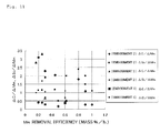
- FIG. 11 is a graph comparing the depletion of C and Si to the Mn removal efficiency.
- the specific surface area of the melt per weight of cast iron in an actual rotary furnace-type impurity removal device is 1.7 m 2 /t
- the specific surface area of the melt is 3 m 2 /t when the treated weight using the small rotary furnace-type impurity removal device (First Embodiment) is 50 kg
- the specific surface area of the melt using the ladle-type impurity removal device is 0.2 m 2 /t.
- FIG. 11 shows the values of ⁇ C/ ⁇ Mn and ⁇ Si/ ⁇ Mn when the depletion amount of carbon ⁇ C and the depletion amount of silicon ⁇ Si are set in relation to the Mn removal efficiency ( ⁇ Mn/h).
- the removal efficiency is preferably 0.55 mass%/h or greater, and at this time, the area in which ⁇ C/ ⁇ Mn and ⁇ Si/ ⁇ Mn are about 1 or less and about 2 or less, respectively, is the preferred range that is thought to be the practical region for operation by a removal device.
- the method for removing impurities of the present invention is capable of removing Mn or other impure elements from molten cast iron, and obtaining pure molten cast iron in which the depletion of C and Si, which are essential elements in cast iron, is suppressed.
- This method can therefore be applied to the field of spheroidal graphite cast iron and the like in which Mn or other impurities considerably hinder elongation and toughness of cast iron raw material.
Abstract
Description
- The present invention relates to a method for removing impurities in molten cast iron, and particularly for removing manganese (hereinafter referred to as "Mn") while suppressing the depletion of carbon (hereinafter referred to as "C") and silicon (hereinafter referred to as "Si"), and also relates to a cast iron raw material manufactured using this method.
- Cast iron is an iron alloy in which the main constituent is iron (hereinafter referred to as "Fe"); in which principal elements C, Si, Mn, phosphorous (hereinafter referred to as "P"), and sulfur (hereinafter referred to as "S") are added; in which copper (Cu), tin (Sn), chromium (Cr), magnesium (hereinafter referred to as "Mg"), nickel (Ni), cobalt (Co), molybdenum (Mo), vanadium (V), niobium (Nb), aluminum (hereinafter referred to as "Al"), titanium (hereinafter referred to as "Ti"), zirconium (hereinafter referred to as Zr), cerium (Ce), calcium (Ca), barium (Ba), bismuth (Bi), and other elements are also added in accordance with the intended purpose; and in which other inevitable impure elements are contained.
- Cast iron raw material is pig-iron, iron scrap, pig iron scrap, return pig iron, turnings, or another main iron source; and a carbon source and other alloy irons for adjusting the C, Si, and other constituents.
- During the manufacture of cast iron, a large amount of iron scrap and the like is used as the main iron source for the raw material in order to reduce cost and energy, and cast iron is an excellent material in terms of recyclability.
- However, in an iron steel material, which is the origin of the iron scrap used as the iron source for the manufacture of cast iron, the added amount of alloy elements other than C and Si tends to be increased for the purpose of higher efficiency, weight saving, higher functionality, and the like. In addition, in the manufacture of high-efficiency iron steel material, comparatively inexpensive Mn is often added in order to reduce costs due to the recent rise in prices of rare metals, and the increase in Mn in iron scrap therefore becomes a problem when iron scrap is used as cast iron raw material.
- The Mn in cast iron is used as an element for stabilizing cementite (Fe3C), which is a compound of Fe and C. In cast iron, the iron matrix structure is therefore changed into perlite, which is a layered structure made of Fe3C and Fe. Hardness and tensile-strength of the cast iron thereby increases, but elongation, toughness, and other properties decrease. In spheroidal graphite cast iron in which graphite in the cast iron is spheroidized by Mg to improve strength and elongation properties, the change of the iron matrix structure has a substantial influence on strength properties. The decrease of elongation and toughness of the graphite cast iron due to an increase in the Mn content in particular is dramatic, and is a problem in terms of manufacturing.
- There is a conventional method for supplying S to molten cast iron and producing MnS as a method for removing Mn from molten cast metal (
Patent Document 1, Patent Document 2). - In this method, however, MnS is produced in the molten cast iron, and problems arise in that the removal treatment is difficult, and a large amount of S additive is required in order to improve removal efficiency.
- On the other hand, Mn removal from ordinary molten iron steel rather than cast iron can be performed employing the following reaction by refinement by the addition of oxygen using a converter furnace or the like.
Mn + 1/2 (O2) → MnO
- However, this reaction is thermodynamically unstable due to the oxidation reaction of C and Si in a melt having a high C and a high Si such as in cast iron, as is apparent from the thermodynamic Ellingham diagram, and at a temperature of 1400°C or more. Accordingly, the useful elements C, Si, and the like are first lost in the removal of Mn when oxygen is supplied to molten cast iron, and a problem arises in that the molten cast iron cannot be formed.
- Because of this, there is proposed a method for manufacturing spheroidal graphite molten cast iron by beginning melting from a cold charge using a pure oxygen rotary furnace, removing Mn using an oxidation reaction while C and Si are depleted, in the same manner as melting ordinary iron steel, and then mixing the result together with a separately prepared molten cast iron having a large amount of C and Si (Patent Document 3).
- In this method, however, the contents of C and Si during melting are reduced, and the melting point of the melt is therefore increased, making a further high-temperature operation necessary. This brings about even further depletion of C and Si. In addition, this method is not practical in terms of manufacturing costs because a simultaneous operation in a separate furnace is necessary.
- In addition, iron oxide or the like is directly added to the molten cast iron melted in an electric furnace or the like, and problems arise in that C and Si are lost in the same manner as in a converter furnace even when the removal of Mn by oxidation is attempted, a large amount of slag is produced, and the operation becomes difficult.
- There is disclosed a method in which iron raw material is heated using the flame of an oxygen burner, and a recarburizer is added while the raw material is melted to manufacture cast iron (Patent Document 4).
- However, this method is a method for improving carbon intake efficiency when carbon is added to molten cast iron, and is a method for manufacturing cast iron having a high concentration of carbon.
- As is shown in each of the aforementioned cited documents, it is difficult to remove Mn in a practical manner using conventional techniques while preventing the depletion of C and Si from molten cast iron.
-
- Patent Document 1: Japanese Laid-Open Patent Publication No.
2003-105420 - Patent Document 2: International Application No.
W02003/083143 - Patent Document 3: Japanese Laid-Open Patent Publication No.
7-268432 - Patent Document 4: Japanese Laid-Open Patent Publication No.
10-8120 - The present invention was devised in order to solve the aforementioned problems, and therefore an object of the present invention is to provide a method for removing impurities in cast iron raw material and obtaining a pure melt in which the impure elements Mn, Al, Ti, Pb, Zn, and B in molten cast iron are removed and the depletion of useful C and Si is suppressed.
- The present invention provides a method for removing impurities including manganese (Mn) while suppressing the depletion of carbon (C) and silicon (Si) included in pre-melted molten cast iron, the method for removing impurities in molten cast iron characterized in comprising: holding the temperature of the molten cast iron at 1250°C or more and less than 1500°C; and directly exposing a surface of the molten cast iron to an excess oxygen flame having a theoretical combustion ratio of fuel and oxygen (amount of oxygen (volume) x 5/amount of fuel (volume)) of 1 to 1.5 while allowing the melt and an acidic slag layer to come into contact with each other to superheat the surface.
- The method is also characterized in that (ΔC/AMn) or (ΔSi/ΔMn) is 2.5 or less when the removal efficiency per unit time of the manganese (Mn) is (ΔMn/h), the removal efficiency per unit time of the carbon (C) is (ΔC/h), and the removal efficiency per unit time of the silicon (Si) is (ΔSi/h).
- The method is also characterized in that an oxygen-containing gas is injected from the interior of the molten cast iron to a surface of the molten cast iron on which the excess oxygen flame is directly exposed, and the oxygen-containing gas is air in particular. The oxygen-containing gas is injected in a ratio of 100 to 1600 (L/min) per 1000 kg of melt.
- The method is also characterized in that elements other than manganese (Mn) removed as impurities in the molten cast iron are at least one of the elements selected from lead (Pb), zinc (Zn), titanium (Ti), aluminum (Al), and boron (B).
- The method for removing impurities in molten cast iron of the present invention is also characterized in that iron oxide is added to the molten cast iron. The method is also characterized in that a device for holding the molten cast iron is a rotary furnace, an electric furnace, a ladle, a cupola desulfurization ladle, or a turn dish, or a combination of thereof.
- The present invention provides a cast iron raw material manufactured using the aforementioned method, the cast iron raw material characterized in being 2 to 4 mass% carbon (C), 0.5 to 4 mass% silicon (Si), 0.1 to 3 mass% manganese (Mn), 0.0001 to 0.03 mass% lead (Pb), 0.0001 to 1.0 mass% zinc (Zn), 0.001 to 0.2 mass% titanium (Ti), 0.0001 to 0.5 mass% aluminum (Al), 0.0001 to 0.04 mass% boron (B), and the remainder being iron (Fe) and inevitable impurities.
- The method for removing impurities in molten cast iron according to the present invention is a method for removing impurities including Mn while suppressing the depletion of C and Si contained in pre-melted molten cast iron, wherein the temperature of the molten cast iron is held at 1250°C or more and less than 1500°C, and an excess oxygen flame having a theoretical combustion ratio of fuel and oxygen of 1 to 1.5 is directly exposed to the surface of the molten cast iron while an acidic slag layer is brought into contact with the melt to superheat the melt surface. It is therefore possible to obtain a pure molten cast iron in which Mn and other impure elements are removed from the molten cast iron and the depletion of C and Si, which are essential elements in cast iron, is suppressed. In spheroidal graphite cast iron in particular, Mn or other impurities substantially hinder the elongation and toughness of cast iron raw material, and the effect of removing Mn or other impure elements is dramatic.
-
-
FIG. 1 is a schematic view showing a treatment state of molten cast iron fed into a treatment device; -
FIG. 2 is a view showing a small rotary furnace-type impurity removal device; -
FIG. 3 is a view showing the C, Si, and Mn contents in the melt, and the treatment time; -
FIG. 4 is a view showing the Pb, Zn, Ti, Al, and B contents in the melt, and the treatment time; -
FIG. 5 is a view showing the effect of bubbling or the like on Mn elimination efficiency in molten cast iron; -
FIG. 6 is a view showing an actual rotary furnace-type impurity removal device; -
FIG. 7 is a view showing the experiment results of the actual rotary furnace-type impurity removal device; -
FIG. 8 is a view showing a ladle-type impurity removal device; -
FIG. 9 is a graph showing experiment results of the ladle impurity removal device; -
FIG. 10 is a graph in which the Mn removal efficiency is organized by specific surface area of the melt; and -
FIG. 11 is a graph showing the relationship between the Mn removal efficiency, and the values of ΔC/ΔMn and ΔSi/ΔMn. - In order to remove the impure elements Mn, Al, Ti, Pb, Zn, and B in molten cast iron and suppress the depletion of useful C and Si, the present inventors performed extensive research and perfected a method for removing impurities, which entails directly exposing flames to the molten cast iron using an oxyfuel burner, and superheating the melt surface.
- In the method of the present invention, pig-iron, iron scrap, pig iron scrap, return pig iron, turnings, and the like are used as the iron source of the raw material, and iron scrap in particular is used as the main iron source.
- Iron scrap of recent years has a large amount of comparatively cheap Mn added for higher efficiency, weight saving, higher functionality, and other improvements to iron steel material, and the Mn must be removed. The method of the present invention can be particularly advantageously applied to iron scrap that includes a large amount of Mn.
- Elements other than Mn, namely Pb, Zn, Ti, Al, or B, can also be removed by the method of the present invention. The method of the present invention is a method for removing these elements, including Mn, from iron scrap.
- The present invention is a treatment method capable of removing 0.2 mass% or more of Mn from molten cast iron that has been pre-melted and holded, the molten cast iron containing, for example, 3 to 4 mass% C, 1 to 3 mass% Si, and 0.5 to 3 mass% Mn.
- In the treatment method, (ΔC/ΔMn) or (ΔSi/ΔMn) is 2.5 or less, where ΔMn is the removal efficiency per unit time of Mn, ΔC is the removal efficiency per unit time of C, and ΔSi is the removal efficiency per unit time of Si. Here, the removal efficiency per unit time is (element amount prior to treatment - element amount after treatment) per unit time.
- It is particularly preferred that the removal rate of Mn be ensured to be at or above 0.6 mass%/h, that ΔC/ΔMn be brought to 1, and that ΔSi/ΔMn be brought to 2 or less.
- The iron scrap is pre-melted prior to the removal of impurities, and is fed to a treatment device. The melted scrap can be made into molten cast iron in the device as long as a treatment device, for example, an electric furnace or other heating and melting equipment is provided.
- The temperature of the molten cast iron when the melt is fed is preferably less than 1500°C, and is more preferably 1250°C or more and less than 1500°C. When the temperature is within this range, the treatment for eliminating Mn while suppressing the depletion of C and Si is facilitated after the melt has been fed.
-
FIG. 1 shows a schematic view expressing the treatment conditions of the molten cast iron fed to the treatment device. - An
excess oxygen flame 2 is directly exposed by aburner 3 to asurface 1a ofmolten cast iron 1 fed to the treatment device, and the melt surface is superheated. InFIG. 1 ,reference numeral 4 is acidic slag, and 5 is an oxygen-containing gas that is injected into themolten cast iron 1. - LPG gas or LNG gas is used as the heat source for the
excess oxygen flame 2, theburner 3 preferably causes combustion while an amount of oxygen is supplied in excess of the amount of oxygen necessary for combustion. Examples of a supply source of excess oxygen include air and pure oxygen gas. - The theoretical combustion ratio of fuel and oxygen (amount of oxygen (volume) x 5/amount of fuel (volume)) is 1.5, and is preferably 1.1 to 1.4. The excess oxygen is insufficient and Mn elimination does not proceed when the theoretical combustion ratio is less than 1, and the temperature of the flame does not increase and Mn elimination does not efficiently proceed when the ratio is 1.5 or more.
- The
excess oxygen flame 2 is directly exposed to thesurface 1a of the molten cast iron. The temperature of thesurface 1a of the molten cast iron during flame exposure is predicted to be 2000°C or more, but the temperature inside 1b of the molten cast iron is held at 1250°C or more and less than 1500°C. - Means for holding the temperature inside of the molten cast iron within this range include means for controlling the amount of melt and fuel used, the amount of
gas 5 injected into the melt inFIG. 1 , the amount of preheat of the treatment device, and therefore, the temperature of the refractory material in this case. - The
surface 1a of the molten cast iron is covered by theacidic slag 4 until the melt temperature reaches 1400°C in accordance with the start of the impurities removing treatment, but theexcess oxygen flame 2 is directly exposed to thesurface 1a of the molten cast iron, and theslag 4 on the exposed portion is thereby eliminated. As a result, theflame 2 makes direct contact with thesurface 1a of the molten cast iron. The surface lc that is not exposed to theflame 2 contacts the acidic slag 4 (FIG. 1 ). - The melt surface is directly exposed to the flame, the impurity removal treatment is performed without increasing the temperature of the entire melt while the remaining melt surface is made to be in contact with the acidic slag, and it is thought that the depletion of C and Si can thereby be reduced while oxidation and removal of Mn progresses.
- The
molten cast iron 1 is agitated by the injection of the oxygen-containinggas 5. Air is preferably used as the oxygen-containing gas. In addition, the injected amount is preferably 100 (L/min) or more and 1600 (L/min) or less per melt weight, and more preferably 200 (L/min) or more and less than 800 (L/min). The force for agitating the melt is insufficient when the injection amount is low, and the temperature of the melt is excessively reduced due to the heat removed by the gas when the injection amount is too high. - In addition, the oxygen-containing
gas 5 is injected from the interior of the molten cast iron so that bubbles of thegas 5 migrate to thesurface 1a of the molten cast iron, which is directly exposed to theexcess oxygen flame 2 and superheated (FIG. 1 ). In the treatment method of the present invention, the reaction at thesurface 1a of the molten cast iron directly exposed to theflame 2 is important, and the surface reaction is accelerated by injecting the oxygen-containinggas 5. - A treatment device in which the molten cast iron is accommodated can be used as long as the device is a treatment device having a shape in which the
melt 1 is directly exposed to theflame 2. Examples of treatment devices that can be used include a rotary furnace, an electric furnace, a ladle, a cupola desulfurization ladle, or a turn dish, or a combination thereof. - In the cast iron raw material manufactured in accordance with the present invention, Mn and other impurities can be reduced while the depletion of useful C and Si is suppressed. It is possible to readily manufacture a cast iron raw material having 2 to 4 mass% C, 0.5 to 4 mass% Si, 0.1 to 3 mass% Mn (preferably 0.1 to 1 mass% Mn), 0.0001 to 0.03 mass% Pb (preferably 0.0001 to 0.02 mass% Pb), 0.0001 to 1.0 mass% Zn (preferably 0.0001 to 0.02 mass% Zn), 0.001 to 0.2 mass% Ti, 0.0001 to 0.5 mass% Al (preferably 0.0001 to 0.2 mass% Al), 0.0001 to 0.04 mass% B (preferably 0.0001 to 0.01 mass% B), and the remainder being Fe and inevitable impurities.
- Impurities in cast iron raw material were removed by a small rotary furnace-type impurity removal device shown in
FIG. 2 . In the small rotary furnace-typeimpurity removal device 6, theburner 3 is disposed in the upper part of the device so that theflame 2 of a burner is directly exposed to the surface of themelt 1 accommodated inside of afurnace 6a to superheat the surface. Thedevice 6 has the shape of a melt holding furnace disposed in front of a general cast iron melting furnace, but this shape is not necessarily required as long as the furnace has a shape in which themelt 1 can be directly exposed to theflame 2 and superheated. InFIG. 2 ,reference numeral 10 indicates an exhaust duct. - After the device is preheated, the pretreated molten cast iron shown in
FIG. 1 is separately melted in advance, and fed to theremoval device 6. The treatment was carried out with 50 kg of melt by weight.[Table 1] Element C Si Mn Pb Zn Al Ti B Fe Content (mass %) Pre-treatment 3.71 2.25 0.75 0.01 0.007 0.01 0.015 0.005 Remainder Post-treatment 3.5 1.80 0.20 0.0002 0.0003 0.0004 0.003 0.0002 Remainder - The surface of the pre-treated molten cast iron shown in TABLE.1 was directly exposed to the burner flame and an impure element removal experiment was performed. The experiment conditions are shown below.
- (1) Theoretical combustion ratio (A) of fuel and oxygen: three levels of 1, 1.2, and 1.5
- (2) Added amount of iron oxide (% relative to melt amount): two levels of 0 and 2 mass%
- (3) Treatment time: 80 min (measurement sample taken every 10 min)
- (4) Measured elements: Mn, C, Si, Pb, Zn, Ti, Al, B
- The melt temperature at the start of the experiment was 1300°C, and the heat input was adjusted so that the melt temperature after about one hour was 1450°C. A test specimen for chemical composition analysis was collected, and at the same time the melt temperature, the gas composition at the exhaust gas outlet, and the amount of dissolved oxygen in the melt was measured. The melt surface was covered by acidic slag until the melt temperature reached 1400°C. The composition of the treated cast iron raw material is shown in Table 1, and the experiment results are shown in
FIGS. 3 to 5 . -
FIG. 3 shows the C, Si, and Mn contents in the melt that change with the progression of the treatment period. The initial amount of Mn decreased from 0.8 mass% to 0.2 mass%, and the Mn amount was successfully removed with best efficiency when treatment was performed at a theoretical combustion ratio (λ) of fuel and oxygen of 1.2, and 2 mass% iron oxide was added (black triangular mark inFIG. 3 ). - The removal efficiency at this time was 0.6 wt%/h, and ΔC/ΔMn was successfully brought to 0.37 and ΔSi/ΔMn to 1.7 or less, where the depletion amount of carbon is ΔC and the depletion amount of silicon is ΔSi in relation to the Mn removal amount ΔMn. In addition, the removal efficiency worsened to 0.45 mass%/h when the ratio of fuel and oxygen (λ) was less than 1. The increase in temperature of the melt was suppressed due to cooling from the excess oxygen, and the treatment time was increased along with an increase in the required fuel amount when the ratio of fuel and oxygen exceeded 1.5.
-
FIG. 4 shows the change in Pb, Zn, Ti, Al, and B contents in the melt that change with the progression of the treatment period. -
FIG. 5 shows the influence of Si amount, swing, and air-bubbling in the molten cast iron on the Mn elimination efficiency. The efficiency increases by reducing the amount of Si, and it is apparent that the Mn elimination efficiency is further increased by swing and air-bubbling. - The flame temperature of the pure oxygen burner used in the small rotary furnace-type impurity removal device is estimated to exceed 2000°C. However, the measured temperature of the molten cast iron was in a range of 1250°C or more to less than 1500°C, and did not rise to 2000°C. It is thought that a high-temperature state is reached only on the extreme surface of the melt. The melt surface is directly exposed to the flame and superheated, whereby the impurities are removed without increasing the temperature of the entire remaining melt, and it is thought that the depletion of C and Si is suppressed as oxidation and removal of Mn progresses.
-
FIG. 6 shows an actual rotary furnace-type impurity removal device. In an actual rotary furnace-typeimpurity removal device 7, threeburners 3 are disposed in the upper part of the device so that theflame 2 of theburners 3 is directly exposed to the surface of themelt 1 accommodated in afurnace 7a. In addition, thegas 5 is blown into the lower part of theflame 3 from the interior of themelt 1 by twolances 9. Impurities in the cast iron raw material were removed using this device. The treatment was carried out with 500 kg and 1000 kg of melt by weight fed to thetreatment device 7. The experiment conditions are shown below. - (1) Theoretical combustion ratio (λ) of fuel and oxygen: 1.2
- (2) Amount of air injected by the lances: 100 L/min, 200 L/min per lance
- (3) Treatment time: 120 min (measurement sample taken every 10 min)
- (4) Measured element: Mn
- The results of the experiment are shown in
FIG. 7 . - The Mn removal efficiency was 0.1 mass%/h when air was not injected, 0.4 mass%/h when air was injected at 100 L/min, and 1.0 mass%/h when air was injected at 200 L/min, respectively. Agitation of the melt by the gas improved the Mn removal efficiency.
- Mn prior to treatment was 0.7 mass% and after treatment was 0.2 mass% when the theoretical ratio λ of fuel and oxygen was 1.2 and the amount of injected air was 200 L/min, and the time necessary for treatment was 30 min per 500 kg. In the same way, C prior to treatment was 3.7 mass% and after treatment was 3.4 mass%, and Si prior to treatment was 2.7 mass% and after treatment was 2.1 mass%. At this time, ΔC/ΔMn was 0.6, and ΔSi/ΔMn was 1.2.
-
FIG. 8 shows a ladle-type impurity removal device. In a ladle-typeimpurity removal device 8, theburner 3 is disposed above an ordinary ladle for cast iron so that theflame 2 of theburner 3 is directly exposed to the surface of themelt 1 accommodated in afurnace 8a. In addition, thegas 5 is blown into the bottom part of theflame 2 from inside of themelt 1 by thelance 9. Impurities in cast iron raw materials were removed using this device. The treatment was carried out with 500 kg of melt by weight fed to thetreatment device 8. The experiment conditions are shown below. - (1) Theoretical combustion ratio (λ) of fuel and oxygen: 1.2
- (2) Amount of air injected by the lance: three levels of 100 L/min, 200 L/min, 400 L/min
- (3) Treatment time: 60 min
- (4) Measured element: Mn
- The experiment results are shown in
FIG. 9. FIG. 9 shows the agitation efficiency of the melt based on the injection of air, the agitation efficiency being converted to agitation energy (W/h) in the following formula. The Mn elimination efficiency obtained in the Second Embodiment is shown as well.
where, - ε̇ :
- agitation energy of melt (W/t)
- Vg :
- amount of gas (volume)
- Te :
- temperature of melt (K)
- Me :
- amount of melt (t)
- h0 :
- length of lance (m)
- η :
- constant
- Tg :
- temperature of gas (K)
-
FIGS. 10 and11 show a summary of the results obtained in each of the embodiments.FIG. 10 is a graph showing the results in which the Mn removal efficiency is sorted by the specific surface area of the melt per weight of molten cast iron, andFIG. 11 is a graph comparing the depletion of C and Si to the Mn removal efficiency. - The specific surface area of the melt per weight of cast iron in an actual rotary furnace-type impurity removal device (Second Embodiment) is 1.7 m2/t, the specific surface area of the melt is 3 m2/t when the treated weight using the small rotary furnace-type impurity removal device (First Embodiment) is 50 kg, and the specific surface area of the melt using the ladle-type impurity removal device (Third Embodiment) is 0.2 m2/t.
- It is apparent from
FIG. 10 that the Mn removal efficiency improves as the specific surface area of the melt increases. -
FIG. 11 shows the values of ΔC/ΔMn and ΔSi/ΔMn when the depletion amount of carbon ΔC and the depletion amount of silicon ΔSi are set in relation to the Mn removal efficiency (ΔMn/h). When consideration is given to the practicality of the Mn elimination treatment, the removal efficiency is preferably 0.55 mass%/h or greater, and at this time, the area in which ΔC/ΔMn and ΔSi/ΔMn are about 1 or less and about 2 or less, respectively, is the preferred range that is thought to be the practical region for operation by a removal device. - The method for removing impurities of the present invention is capable of removing Mn or other impure elements from molten cast iron, and obtaining pure molten cast iron in which the depletion of C and Si, which are essential elements in cast iron, is suppressed. This method can therefore be applied to the field of spheroidal graphite cast iron and the like in which Mn or other impurities considerably hinder elongation and toughness of cast iron raw material.
-
- 1
- Molten cast iron
- 2
- Excess oxygen flame
- 3
- Burner
- 4
- Acidic slag
- 5
- Gas injected into molten cast iron
- 6
- Small rotary furnace-type impurity removal device
- 7
- Actual rotary furnace-type impurity removal device
- 8
- Ladle-type impurity removal device
- 9
- Lance
- 10
- Exhaust duct
Claims (9)
- A method for removing impurities including manganese (Mn) while suppressing the depletion of carbon (C) and silicon (Si) included in pre-melted molten cast iron, the method for removing impurities in molten cast iron characterized in comprising: holding the temperature of the molten cast iron at 1250°C or more and less than 1500°C; and directly exposing a surface of the molten cast iron to an excess oxygen flame having a theoretical combustion ratio of fuel and oxygen (amount of oxygen (volume) x 5/amount of fuel (volume)) of 1 to 1.5 while allowing the melt and an acidic slag layer to come into contact with each other to superheat the surface.
- The method for removing impurities in molten cast iron of claim 1, characterized in being a method in which (ΔC/ΔMn) or (ΔSi/ΔMn) is 2.5 or less when the removal efficiency per unit time of the manganese (Mn) is (ΔMn/h), the removal efficiency per unit time of the carbon (C) is (ΔC/h), and the removal efficiency per unit time of the silicon (Si) is (ΔSi/h).
- The method for removing impurities in molten cast iron of claim 1 or 2, characterized in that an oxygen-containing gas is injected from the interior of the molten cast iron to a surface of the molten cast iron on which the excess oxygen flame is directly exposed.
- The method for removing impurities in molten cast iron of claim 3, characterized in that the oxygen-containing gas is air.
- The method for removing impurities in molten cast iron of claim 3 or 4, characterized in that the oxygen-containing gas is injected at 100 to 1600 (L/min) per 1000 kg of melt.
- The method for removing impurities in molten cast iron of any of claims 1 to 5, characterized in that elements other than manganese (Mn) removed as impurities in the molten cast iron are at least one of the elements selected from lead (Pb), zinc (Zn), titanium (Ti), aluminum (Al), and boron (B).
- The method for removing impurities in molten cast iron of any of claims 1 to 6, characterized in that iron oxide is added to the molten cast iron.
- The method for removing impurities in molten cast iron of any of claims 1 to 7, characterized in that a device for holding the molten cast iron is a rotary furnace, an electric furnace, a ladle, a cupola desulfurization ladle, or a turn dish, or a combination thereof.
- A cast iron raw material manufactured using the method of claim 1, the cast iron raw material characterized in being 2 to 4 mass% carbon (C), 0.5 to 4 mass% silicon (Si), 0.1 to 3 mass% manganese (Mn), 0.0001 to 0.03 mass% lead (Pb), 0.0001 to 1.0 mass% zinc (Zn), 0.001 to 0.2 mass% titanium (Ti), 0.0001 to 0.5 mass% aluminum (Al), 0.0001 to 0.04 mass% boron (B), and the remainder being iron (Fe) and inevitable impurities.
Applications Claiming Priority (2)
| Application Number | Priority Date | Filing Date | Title |
|---|---|---|---|
| JP2010016251A JP5150654B2 (en) | 2010-01-28 | 2010-01-28 | Method for removing impurities in cast iron melt and cast iron raw material |
| PCT/JP2011/051195 WO2011093237A1 (en) | 2010-01-28 | 2011-01-24 | Method for removing impurities in molten cast iron, and cast iron raw material |
Publications (2)
| Publication Number | Publication Date |
|---|---|
| EP2530171A1 true EP2530171A1 (en) | 2012-12-05 |
| EP2530171A4 EP2530171A4 (en) | 2015-07-15 |
Family
ID=44319225
Family Applications (1)
| Application Number | Title | Priority Date | Filing Date |
|---|---|---|---|
| EP11736950.4A Withdrawn EP2530171A4 (en) | 2010-01-28 | 2011-01-24 | Method for removing impurities in molten cast iron, and cast iron raw material |
Country Status (6)
| Country | Link |
|---|---|
| US (1) | US20130195712A1 (en) |
| EP (1) | EP2530171A4 (en) |
| JP (1) | JP5150654B2 (en) |
| KR (1) | KR20130001227A (en) |
| CN (1) | CN102782163B (en) |
| WO (1) | WO2011093237A1 (en) |
Cited By (1)
| Publication number | Priority date | Publication date | Assignee | Title |
|---|---|---|---|---|
| RU2508417C1 (en) * | 2013-03-13 | 2014-02-27 | Юлия Алексеевна Щепочкина | Cast iron |
Families Citing this family (5)
| Publication number | Priority date | Publication date | Assignee | Title |
|---|---|---|---|---|
| CN102747265B (en) * | 2012-06-07 | 2014-02-26 | 兰州理工大学 | Raw materials and method for preparing white cast iron, and white cast iron structure |
| RU2529343C1 (en) * | 2013-12-12 | 2014-09-27 | Юлия Алексеевна Щепочкина | Cast iron |
| US20170342515A1 (en) * | 2014-12-12 | 2017-11-30 | Kinoshita Manufactory Co.,Ltd. | Methods for manganese removal of cast iron |
| CN104894467A (en) * | 2015-06-08 | 2015-09-09 | 谢伟杰 | Wear-resisting cast iron |
| WO2017141145A1 (en) * | 2016-02-16 | 2017-08-24 | Dominic Sabukutty | Method for pre-treatment of molten iron with special grades of iron ore |
Family Cites Families (16)
| Publication number | Priority date | Publication date | Assignee | Title |
|---|---|---|---|---|
| CA924907A (en) * | 1969-03-21 | 1973-04-24 | British Steel Corporation | Manganese control |
| BE756083A (en) * | 1969-09-11 | 1971-03-15 | Enya Ryosuke | METHOD AND DEVICE FOR THE MANUFACTURE OF FUSION METAL INTENDED TO BE CAST |
| US4130419A (en) * | 1977-03-11 | 1978-12-19 | Linde Ag | Process for the purification, modification and heating of a cast-iron melt |
| DE2727093A1 (en) * | 1977-06-15 | 1979-01-04 | Linde Ag | Removal of manganese and silicon from a cast iron melt - by an oxygen blow and addn. of slag formers |
| US4402739A (en) * | 1982-07-13 | 1983-09-06 | Kawasaki Steel Corporation | Method of operation of a top-and-bottom blown converter |
| JPS59126706A (en) * | 1983-01-08 | 1984-07-21 | Kubota Ltd | Treatment of molten iron |
| JPS59126705A (en) * | 1983-01-08 | 1984-07-21 | Kubota Ltd | Treatment of molten iron |
| JPS61163203A (en) * | 1985-01-10 | 1986-07-23 | Nippon Steel Corp | Method for removing mn from molten iron |
| JPH07268432A (en) | 1994-04-01 | 1995-10-17 | Hitachi Metals Ltd | Production of spheroidal graphite cast iron by rotary furnace utilizing pure oxygen |
| JP3662348B2 (en) | 1996-06-17 | 2005-06-22 | 大陽日酸株式会社 | Iron melting furnace and method for producing cast iron |
| JPH10330816A (en) * | 1997-06-05 | 1998-12-15 | Nippon Sanso Kk | Production of cast iron |
| JP4718739B2 (en) | 2001-09-27 | 2011-07-06 | 新日本製鐵株式会社 | Demanganese treatment method for cast iron |
| CN1448521A (en) * | 2002-03-28 | 2003-10-15 | 旭技术株式会社 | Method for removing manganese in cast iron molten liquid and method for manufacturing nodular graphite cast iron |
| JP2007332432A (en) * | 2006-06-16 | 2007-12-27 | Katsuhiko Yamada | Method for refining molten steel |
| JP2008045165A (en) * | 2006-08-12 | 2008-02-28 | Iwate Industrial Research Center | Method for removing impurity from molten cast iron |
| DE102009004189B4 (en) * | 2009-01-09 | 2013-07-25 | Man Truck & Bus Ag | Component of a cast iron alloy, in particular for cylinder heads |
-
2010
- 2010-01-28 JP JP2010016251A patent/JP5150654B2/en not_active Expired - Fee Related
-
2011
- 2011-01-24 US US13/575,859 patent/US20130195712A1/en not_active Abandoned
- 2011-01-24 KR KR1020127022412A patent/KR20130001227A/en not_active Application Discontinuation
- 2011-01-24 WO PCT/JP2011/051195 patent/WO2011093237A1/en active Application Filing
- 2011-01-24 EP EP11736950.4A patent/EP2530171A4/en not_active Withdrawn
- 2011-01-24 CN CN201180007330.8A patent/CN102782163B/en active Active
Cited By (1)
| Publication number | Priority date | Publication date | Assignee | Title |
|---|---|---|---|---|
| RU2508417C1 (en) * | 2013-03-13 | 2014-02-27 | Юлия Алексеевна Щепочкина | Cast iron |
Also Published As
| Publication number | Publication date |
|---|---|
| JP2011153359A (en) | 2011-08-11 |
| WO2011093237A1 (en) | 2011-08-04 |
| CN102782163A (en) | 2012-11-14 |
| EP2530171A4 (en) | 2015-07-15 |
| US20130195712A1 (en) | 2013-08-01 |
| KR20130001227A (en) | 2013-01-03 |
| JP5150654B2 (en) | 2013-02-20 |
| CN102782163B (en) | 2014-12-31 |
Similar Documents
| Publication | Publication Date | Title |
|---|---|---|
| CN102277534B (en) | Hot rolled steel section for gas cylinders and production method thereof | |
| EP2530171A1 (en) | Method for removing impurities in molten cast iron, and cast iron raw material | |
| CN102758144B (en) | Production method for steel ingot of large-sized high-nitrogen retaining ring steel | |
| RU2739040C1 (en) | Method of producing ferrotungsten based on reduction of self-propagating gradient of aluminothermy and slag refining | |
| CN102268608B (en) | Large capacity high pressure gas cylinder steel and production method thereof | |
| CN107245637A (en) | A kind of AOD smelts the method and a kind of AOD furnace of high manganese stainless steel | |
| JP2010144195A (en) | Method for manufacturing high nitrogen-containing stainless steel | |
| CN100540685C (en) | direct steel alloying method | |
| WO2012149635A1 (en) | Process of the production and refining of low-carbon dri (direct reduced iron) | |
| JP5135846B2 (en) | Operation method of storage furnace | |
| RU2254380C1 (en) | Method of production of rail steel | |
| CN109055661A (en) | A kind of production technology of low-phosphorous stainless steel | |
| Yessengaliyev et al. | Feasibility study of using with high basicity manganese ore for smelting refined ferromanganese | |
| JP4655573B2 (en) | Method for oxidative dephosphorization of chromium-containing hot metal | |
| US8641800B2 (en) | Method of alloying various grades of steel with manganese oxides | |
| RU2384627C1 (en) | Steel-making method in arc electric steel-smelting furnace | |
| SU1659493A1 (en) | Method of deoxidizing and alloying of low-carbon vanadium-bearing electric steel | |
| RU2092571C1 (en) | Composite charge for making steel | |
| RU2364632C2 (en) | Steel production method | |
| RU2186856C1 (en) | Composite blend for smelting alloyed steels | |
| SU85123A1 (en) | ||
| KR100887859B1 (en) | The method of manufacturing stainless steel through reduction of chromium ore | |
| Ray et al. | Studies on pyrometallurgy of vanadium bearing iron, steel and slag | |
| US1066810A (en) | Thermal treatment of metal in electrically-heated furnaces. | |
| RU2455367C2 (en) | Method to produce automobile-body steel |
Legal Events
| Date | Code | Title | Description |
|---|---|---|---|
| PUAI | Public reference made under article 153(3) epc to a published international application that has entered the european phase |
Free format text: ORIGINAL CODE: 0009012 |
|
| 17P | Request for examination filed |
Effective date: 20120814 |
|
| AK | Designated contracting states |
Kind code of ref document: A1 Designated state(s): AL AT BE BG CH CY CZ DE DK EE ES FI FR GB GR HR HU IE IS IT LI LT LU LV MC MK MT NL NO PL PT RO RS SE SI SK SM TR |
|
| DAX | Request for extension of the european patent (deleted) | ||
| RA4 | Supplementary search report drawn up and despatched (corrected) |
Effective date: 20150615 |
|
| RIC1 | Information provided on ipc code assigned before grant |
Ipc: C21C 1/04 20060101ALI20150609BHEP Ipc: C22C 37/00 20060101ALI20150609BHEP Ipc: C22C 37/10 20060101ALI20150609BHEP Ipc: C21C 1/08 20060101AFI20150609BHEP |
|
| STAA | Information on the status of an ep patent application or granted ep patent |
Free format text: STATUS: THE APPLICATION IS DEEMED TO BE WITHDRAWN |
|
| 18D | Application deemed to be withdrawn |
Effective date: 20160113 |