EP2605032A1 - Localization method and system using non-regenerative UWB relays - Google Patents
Localization method and system using non-regenerative UWB relays Download PDFInfo
- Publication number
- EP2605032A1 EP2605032A1 EP11352013.4A EP11352013A EP2605032A1 EP 2605032 A1 EP2605032 A1 EP 2605032A1 EP 11352013 A EP11352013 A EP 11352013A EP 2605032 A1 EP2605032 A1 EP 2605032A1
- Authority
- EP
- European Patent Office
- Prior art keywords
- tag
- relay
- anchor
- node
- nodes
- Prior art date
- Legal status (The legal status is an assumption and is not a legal conclusion. Google has not performed a legal analysis and makes no representation as to the accuracy of the status listed.)
- Granted
Links
- 230000001172 regenerating effect Effects 0.000 title claims abstract description 37
- 238000000034 method Methods 0.000 title claims abstract description 21
- 230000004807 localization Effects 0.000 title description 31
- 238000012545 processing Methods 0.000 claims abstract description 25
- 238000007476 Maximum Likelihood Methods 0.000 claims description 11
- 238000013459 approach Methods 0.000 description 4
- 238000004891 communication Methods 0.000 description 4
- 230000001934 delay Effects 0.000 description 4
- 230000001427 coherent effect Effects 0.000 description 3
- 238000001514 detection method Methods 0.000 description 3
- 230000003321 amplification Effects 0.000 description 2
- 230000005540 biological transmission Effects 0.000 description 2
- 230000003111 delayed effect Effects 0.000 description 2
- 238000013461 design Methods 0.000 description 2
- 230000014509 gene expression Effects 0.000 description 2
- 238000003199 nucleic acid amplification method Methods 0.000 description 2
- 230000003595 spectral effect Effects 0.000 description 2
- 238000005314 correlation function Methods 0.000 description 1
- 230000008878 coupling Effects 0.000 description 1
- 238000010168 coupling process Methods 0.000 description 1
- 238000005859 coupling reaction Methods 0.000 description 1
- 230000001419 dependent effect Effects 0.000 description 1
- 238000010586 diagram Methods 0.000 description 1
- 238000002592 echocardiography Methods 0.000 description 1
- 238000005516 engineering process Methods 0.000 description 1
- 238000009413 insulation Methods 0.000 description 1
- 238000005259 measurement Methods 0.000 description 1
- 230000000116 mitigating effect Effects 0.000 description 1
- 230000001360 synchronised effect Effects 0.000 description 1
Images


Classifications
-
- G—PHYSICS
- G08—SIGNALLING
- G08B—SIGNALLING OR CALLING SYSTEMS; ORDER TELEGRAPHS; ALARM SYSTEMS
- G08B13/00—Burglar, theft or intruder alarms
- G08B13/22—Electrical actuation
- G08B13/24—Electrical actuation by interference with electromagnetic field distribution
- G08B13/2402—Electronic Article Surveillance [EAS], i.e. systems using tags for detecting removal of a tagged item from a secure area, e.g. tags for detecting shoplifting
- G08B13/2451—Specific applications combined with EAS
- G08B13/2462—Asset location systems combined with EAS
-
- G—PHYSICS
- G01—MEASURING; TESTING
- G01S—RADIO DIRECTION-FINDING; RADIO NAVIGATION; DETERMINING DISTANCE OR VELOCITY BY USE OF RADIO WAVES; LOCATING OR PRESENCE-DETECTING BY USE OF THE REFLECTION OR RERADIATION OF RADIO WAVES; ANALOGOUS ARRANGEMENTS USING OTHER WAVES
- G01S5/00—Position-fixing by co-ordinating two or more direction or position line determinations; Position-fixing by co-ordinating two or more distance determinations
- G01S5/02—Position-fixing by co-ordinating two or more direction or position line determinations; Position-fixing by co-ordinating two or more distance determinations using radio waves
- G01S5/0273—Position-fixing by co-ordinating two or more direction or position line determinations; Position-fixing by co-ordinating two or more distance determinations using radio waves using multipath or indirect path propagation signals in position determination
-
- G—PHYSICS
- G01—MEASURING; TESTING
- G01S—RADIO DIRECTION-FINDING; RADIO NAVIGATION; DETERMINING DISTANCE OR VELOCITY BY USE OF RADIO WAVES; LOCATING OR PRESENCE-DETECTING BY USE OF THE REFLECTION OR RERADIATION OF RADIO WAVES; ANALOGOUS ARRANGEMENTS USING OTHER WAVES
- G01S5/00—Position-fixing by co-ordinating two or more direction or position line determinations; Position-fixing by co-ordinating two or more distance determinations
- G01S5/02—Position-fixing by co-ordinating two or more direction or position line determinations; Position-fixing by co-ordinating two or more distance determinations using radio waves
- G01S5/0284—Relative positioning
- G01S5/0289—Relative positioning of multiple transceivers, e.g. in ad hoc networks
Landscapes
- Physics & Mathematics (AREA)
- Engineering & Computer Science (AREA)
- General Physics & Mathematics (AREA)
- Radar, Positioning & Navigation (AREA)
- Remote Sensing (AREA)
- Automation & Control Theory (AREA)
- Computer Security & Cryptography (AREA)
- Electromagnetism (AREA)
- Radar Systems Or Details Thereof (AREA)
Abstract
Description
- The present application relates in general to the field of radio locating systems, in particular realtime locating systems (RLTS). It also relates to the field of IR-UWB (Impulse Radio Ultra Wide Band) communications.
- A real time locating system (RTLS) usually involves an infrastructure comprising a plurality of fixed nodes in known positions, also called anchors or anchor nodes, and at least an object, generally provided with a tag affixed thereon or embedded therein, the position of which has to be determined.
- The anchors interact with the tag and determine its position by sending and/or receiving wireless signals and measuring certain characteristics thereof.
- Generally, tags can be classified into active tags, i.e. comprising an autonomously powered wireless transmitter, and passive tags, which merely reflect or backscatter the signals they receive.
- Common methods to determine the position of the tags are based on time-of-arrival (TOA), time difference-of-arrival (TDOA), received signal strength (RSS) and angle-of-arrival (AOA).
- Future RTLSs are expected to provide high-definition localization of objects with improved reliability and security while maintaining low power consumption and cost. High accuracy localization, even in harsh environments such as indoor and industrial scenarios, can be obtained by using ultra-wide band (UWB) signals.
- By UWB signal is generally meant a signal complying with the spectral mask stipulated in the FCC regulation as of February 14th 2002, and reviewed in March 2005, i.e. essentially a signal in the spectral band from 3.1 to 10.6 GHz and having a -10dB bandwidth of at least 500 MHz, or a relative band larger than 0.2. In practice, two types of UWB signals are known, the multi-band OFDM (MB-OFDM) signals and the Impulse Radio UWB (IR-UWB) signals. In the following, we will consider the latter only. A UWB pulse signal consists of very short pulses, typically of the order of a few tens to hundred picoseconds, distributed within a frame.
- UWB pulse signals offer the potential of achieving high ranging accuracy through signal TOA measurements due to high bandwidth and ability to resolve multipath. Further advantages of UWB signals include low power consumption at the transmitter side, robustness to multipath, low detection probability, and possibility of having high number of devices operating simultaneously with limited mutual interference.
- Thanks to their low power consumption, IR-UWB transmitters have been adopted successfully for active tags, whereas passive tags have been recently proposed for next generation RFID and low-cost high-accuracy RTLSs.
- The presence of obstacles in real environments gives rise to non line-of-sight (NLOS) channel conditions that may degrade ranging accuracy due to lower signal-to-noise ratio (SNR), multipath, and large delay spread. They may even render ranging impossible, thus leading to a limitation of the coverage area of the localization system.
- Several NLOS mitigation approaches have been presented in the literature.
- One solution to deal with severe NLOS conditions in a localization system is to increase the number of anchor nodes at the expense of higher infrastructure and deployment cost. In particular, if time-based positioning approaches (TOA) are adopted, this implies to keep the anchors tightly synchronized.
- Other solutions are based on cooperative localization algorithms. However these algorithms are carried out in a distributed way among tags. The tags need therefore to be of the active type, equipped with a receiver, and hence have sufficient computational power. These solutions are hardly applicable to design cheap and energy efficient RTLSs.
- Area coverage in RTLS is much more difficult and expensive than area coverage in conventional communication systems. Indeed, while it suffices to be in LOS of a base station or a relay in a communication system, at least three anchor nodes must be visible simultaneously by the tag to enable localization in two dimensions without ambiguity.
- It is often desirable for cost reasons, to reduce the number of anchors regardless the presence or not of NLOS conditions. Cost and the number of anchors can be partially reduced by using low complexity relays acting as regenerative repeaters.
- Extensive literature is available dealing with relays in ad hoc wireless networks or wireless sensor networks for communication reliability enhancement. However, few envisage using relays for localization purposes. For example, patent application
FR-A-2924818 - However, the cost of regenerative relays, their requirements in terms of power supply and synchronization remain major drawbacks. Furthermore, the design of regenerative relays is strictly related to the specific signal format adopted by the RTLS. In particular, this means that the same infrastructure cannot be used for locating active tags using different data formats (encoding or modulation schemes) or for locating both active tags and passive tags.
- The object of the present application is therefore to propose a localization system such as an RTLS, which does not involve the drawbacks recited above, namely which achieves a broad coverage while being simple and robust.
- The present invention is defined in the appended independent claims. Various advantageous embodiments are given in the dependent claims.
- The present invention will be better understood from the description of the following embodiments, by way of illustration and in no way limitative thereto:
-
Fig. 1 schematically represents a localization system according to an embodiment of the invention; -
Fig. 2A represents a first type of non-regenerative relay for use in the localization system ofFig. 1 ; -
Fig. 2B represents a second type of non-regenerative relay for use in the localization system ofFig. 1 ; -
Fig. 2C represents a third type of non-regenerative relay for use in the localization system ofFig. 1 ; -
Fig. 3A represents a first scenario for locating a tag with the localization system ofFig. 1 ; -
Fig. 3B represents an example of signals received by anchor nodes of the localization system in the first scenario; -
Fig. 4A represents a second scenario for locating a tag with the localization system ofFig. 1 ; -
Fig. 4B represents an example of signals received by anchor nodes of the localization system in the second scenario. - We will consider in the following a localization system comprising a plurality of anchor nodes (or anchors) and one or several non-regenerative relay(s). It is assumed that the positions of the anchor nodes (per definition) and of the non-regenerative relays are known.
- By non-regenerative relay it is meant a relay which merely forwards and possibly amplifies an incoming signal. In particular, a non-regenerative relay does not demodulate/ decode the incoming signal to regenerate it. The non-regenerative relays can be of the active type or the passive type, as explained in detail further below.
-
Fig. 1 schematically represents a localization system according to an embodiment of the invention. - This system comprises a plurality NA of anchors, 111, 112, a plurality NR of
non-regenerative relays - The localization system is capable of locating a
tag 140, according to a first localization scenario where the tag is of the active type or according to a second localization scenario when the tag is of the passive type. - It will be noted that the
anchor node 111 is in NLOS condition with respect to tag 140 because of the presence of an obstacle. However, due to the presence of thenon-regenerative relays LOS channel 142 betweentag 140 andanchor node 112 coexists with relayed channel 143,143' (relayed by 123). In general, a signal transmitted by an anchor node can be relayed by one or several relays to the tag. Conversely, a signal transmitted by the tag can be relayed by one or several relays to an anchor node. - The number of anchor nodes and relays is chosen to achieve localization coverage in the zone of interest. In other words, a tag located at an arbitrary position within the zone of interest should see at least three nodes of known positions (anchor nodes or relays).
- The non-regenerative relays 121,122,123 can be of the passive type as shown in
Fig. 2A or of the active type as shown inFigs. 2B and 2C . - The passive non-regenerative relay of
Fig. 2A is simply composed of a first high-gaindirectional UWB antenna 210 and a second directional oromnidirectional UWB antenna 220 connected with acoaxial cable 230. If the first and second antennas are both directional antennas, the first and second antennas are oriented in distinct directions. Hence, a signal received by one of the two antennas is simply forwarded by the other antenna without amplification. Such a relay is also sometimes referred to as a cold repeater or of the just-forward type. -
Fig. 2B shows a first example of an active non-regenerative relay. By active, it is meant that the relay performs an amplification of the received signal. Such a relay is also often referred to as of the amplify-and-forward type. - As above, the relay illustrated in
Fig. 2B comprises afirst UWB antenna 210 and asecond UWB antenna 220. A first duplexer, 215, (e.g. here a circulator) is connected to the first UWB antenna, 210, and a second duplexer, 225, (e.g. a circulator) is connected to the second UWB antenna, 220. A first amplifier, 217, provided between the first and the second duplexers, amplifies the signal received by the first antenna and delivers the amplified signal to the second antenna. A second amplifier, 227, provided between the second and the first duplexer, amplifies the signal received by the second antenna and delivers the amplified signal to the first antenna. A drawback of this scheme is the positive feedback that may arise between the antenna and/ or the lack of insulation of the duplexers. In particular, the mutual coupling between the two antennas must be controlled. According to a variant not shown, for use in the first scenario described further below, relaying can be made unidirectional (from tag to anchors) and therefore amplifier 217 together with circulators 215,225 can be omitted. -
Fig. 2C shows a second example of an active non-regenerative relay which overcomes the aforementioned limitations. - This relay has the same structure as in
Fig. 2B except that theduplexers - The synchronization signal can be provided by an anchor node controlling that specific relay through an auxiliary wireless control channel, or through a cable. Alternatively, the synchronization signals of the various relays can be generated by a centralized control node.
- In any case, synchronization constraints are here much more relaxed compared to that of regenerative relays. According to a variant not shown, for use in the first scenario described further below, relaying can be made unidirectional (from tag to anchors) and therefore amplifier 217 together with switches 216,226 can be omitted. In such instance the relay is further simplified as no synchronization signal is required.
- Whatever their type, the relays are deployed in such a way that their
first antenna 210 is in LOS condition with respect to one preferred anchor node and theirsecond antenna 220 is in LOS condition with respect to a zone of interest intended to be covered e.g. a zone in NLOS with respect to the preferred anchor node. -
Fig. 3A represents a first scenario of use for the localization system ofFig. 1 . The same references designate here the same elements as inFig. 1 . - In this scenario, at least one active tag, 140, is present. This tag emits a UWB pulse signal which is received by the anchor nodes and relays in LOS condition with respect thereto. In the case illustrated, the
anchor node 112 and therelays Anchor node 111 receives the UWB pulse signal respectively relayed byrelays - In general the various transmission channels between the tag and the LOS anchors/ relays can be multipath. The same applies to the channels between the relays and their related anchor nodes. For simplification purpose but without prejudice of generalization, it will be assumed in the following that the transmission channels are single path.
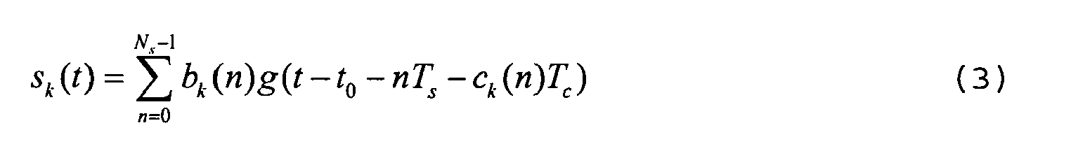
- The UWB pulse signal emitted by the tag is in general a sequence of very short pulses which can be expressed as follows:

where g(t) is the elementary pulse shape, Ts is the duration of an elementary interval, t 0 is the time of emission, and Tf = NsTs is the length of the sequence. - In some instances, each active tag may emit its own sequence modulated by a time-hopping code:

with Ts = NcTc where Nc is the number of chips in an interval, and where ck (n) for n=0,..,Ns -1 defines the time hopping code of tag k. Time hopping codes are selected so as to minimize the number of collisions between pulses belonging to time hopping codes of different tags. - Alternatively or additionally, each tag may emit a sequence modulated by a bipolar code. For example if both time-hopping and bipolar coding is used:
where bk (n), n=0,..,Ns -1, bk (n)=±1, defines the bipolar code of tag k. - For the sake of illustration, we will assume in the following that the signal sent by an active tag is monopulse (Ns =1). It should be clear though that the invention equally applies independently of the length of the sequence and the type of modulation used.
-
Fig. 3B represents the UWB pulse signal received by various anchors of the localization system, in the present instance byanchor nodes - The upper part of the figure shows the UWB pulse signal r 1 (t) received by
anchor 111, and the lower part shows the UWB pulse signal r 2(t) received byanchor 112. In both diagrams, the pulse transmitted by the tag at time t 0 has been represented by 300. - With regard to
anchor 111, the signal r 1(t) comprises afirst pulse 321 which has been relayed bynon-regenerative relay 121 and asecond pulse 322 which has been relayed bynon-regenerative relay 122. The first pulse is received after a delay

relay 121 and
first anchor 111. Similarly, the second pulse is received after a delay

relay 122. - With regard to
anchor 112, the signal r 2(t) comprises a first pulse 340, which has been directly received from the tag and asecond pulse 322 which has been relayed bynon-regenerative relay 123. The first pulse is received after a delay

second anchor 112. The second pulse is received after a delay

relay 123. - More generally, each anchor will receive a LOS UWB pulse signal from the tag and/or one or a plurality of relayed versions thereof.
- Assuming that the signal emitted by the tag at time t 0 is monopulse, the signal received by an anchor m=1,...,NA can be expressed as:

where
- The first term in (4) accounts for the LOS signal, the second term represents the contribution of the relayed signals, and the third term represents the total thermal noise with power density, Nm due to the receiver as well as the relays. The LOS signal and the relayed signals are referred hereinafter to as path components of the received signal rm (t). The channel gain w(p,q) accounts for the transmitted power, antenna gains, path-loss coefficient of the LOS channel between nodes of positions p and q. In particular, if no LOS channel exists between these two nodes, the channel gain is null (w(p,q)=0). In general, the channel gain can be expressed as:

where L(p,q) is the path loss coefficient of the channel between the nodes (a log-normal shadowing model can be assumed). The coefficient L(p,q) and hence the channel gain can be estimated from the environment knowledge. - The signals rm (t), m=1,...,NA, received by the anchors are collected by the
processing node 130. The processing node comprises a processing unit which derives the position p of the tag from these signals. More specifically, the processing unit determines the coordinates of the position p and the time of emission t 0 from the time distribution of the pulses in the received signals rm (t). This is possible if the number of anchors and the number of relays in LOS condition of the tag is sufficiently high to remove any spatial ambiguity. - Various algorithms can be used for this purpose. One possible algorithm is based on a ML (Maximum-Likelihood) approach. In such instance, one may use the following log-ML function l(p,t 0) depending upon the position p of the tag and the time of emission t 0:

where T is an observation window chosen long enough to accommodate all the useful signal echoes, i.e. all the possible relayed versions of the UWB pulse signal emitted by the tag. It should be understood that the first term in (6) is a correlation term whereas as the second represents the total signal-to-noise ratio. - The log-ML function can be rewritten by expressing the received signals according to (4):

where:
and
- If the UWB pulse signal is not monopulse, the pulse shape g(t-τ) has to be replaced by


- At any rate, the processing unit maximizes the log-ML function l(p,t 0) over the possible values of p and t 0. The ML estimate of the position of the tag is then given by:

- Other algorithms can equally be employed to estimate the position of the tag from the received signals rm (t), m=1,...,NA. For example, it is possible to determine the time of arrival of each path component of the received signal by using a non-coherent receiver such as the one described in the article of D. Dardari et al. entitled "Ranging with ultrawide bandwidth signals in multipath environment" published in Proc. of IEEE Special Issue on UWB technology & emerging applications, vol. 97, No. 2, pp. 404-426, Feb. 2009. More specifically, each signal rm (t) can be subjected, possibly after de-hopping and/or demodulating, to energy detection within a plurality of consecutive time windows. The energy values in these windows can be compared with a threshold to determine the times of arrival of the path components within rm (t). The various path components are identified according to their respective intensities and the channel gains


- The position p can then be obtained according to a conventional TDOA algorithm. Alternatively, non-coherent ML estimators can be adopted leading to a likelihood function similar to (7) and (10), where no knowledge of the received pulse g(t) is required at the receiver.
-
Fig. 4A represents a second scenario of use of the localization system ofFig. 1 . Again, the same references designate here the same elements as inFig. 1 . - In this scenario, at least one
passive tag 140 is present. Each anchor node emits an interrogating UWB pulse signal modulated by a unique code, e.g. a unique hopping code and/or a unique bipolar code as explained above. This signal may be repeated by one or more non-regenerative relays until it reaches the passive tag. - In the case illustrated, the interrogating UWB pulse signal emitted by
anchor node 111 is relayed byrelays tag 140. The signal received by the tag is then reflected back towardanchor node 111 following a two-hop path through therelays nodes - Similarly, the UWB pulse signal emitted by
anchor node 112 is directly received by the tag and received after being repeated byrelay 122. The signal received by the tag is then reflected back following the LOS path and the two-hop path through relay 123 (see broken lines). -
Fig. 4B represents the UWB signals received by the anchor node 111 (upper part) and anchor node 112 (lower part). - For the sake of illustration, it has been assumed that the interrogating signal is constituted by a single pulse. However, in practice, it is recalled that the interrogating signal can be a sequence of short pulses modulated by a hopping code and/or a bipolar code.
- The signal received by
anchor node 111, r 1(t), comprises afirst pulse 421, which has travelled along the path
second pulse 422, which has travelled along the path


pulse 400 emitted byanchor node 111 has also been represented for showing the round trip propagation delays. With respect to the interrogating pulse, the first pulse is delayed by

- Turning now to the lower part of the figure, the signal received by
anchor node 112, r 2(t), comprises a first pulse 440, which has travelled along the LOS path

pulse 400 emitted byanchor node 112, the first pulse 440 exhibits adelay 
delay 
- More generally, each anchor of the localization system sends a UWB pulse signal coded with a unique code and receives the signal after reflection on the tag. The signal may have travelled along a LOS path or on a relayed path on its way to the tag or back. The signal received by the tag from an anchor node m can be expressed as:

- It will be understood that the first term in expression (11) accounts for the LOS path and the second for the relayed paths.
- The
passive tag 140 reflects or backscatters the incoming signals
- Assuming a single tag is present, the signal received from the tag by anchor node m can be expressed as:

- The received signals rm (t), m=1,...,NA , are forwarded to the
central processing node 130. The processing unit therein proceeds to the estimation of the position p of the tag from the time distribution of the pulses in the received signals rm (t). - The processing unit may adopt for example a ML or log-ML estimation method. In such instance, the log-ML function can be expressed as:

where Em is defined as in (9) and:
accounts for the signals having travelled along a two-hop path to and from the tag, qm (τ) being defined as in (8) ;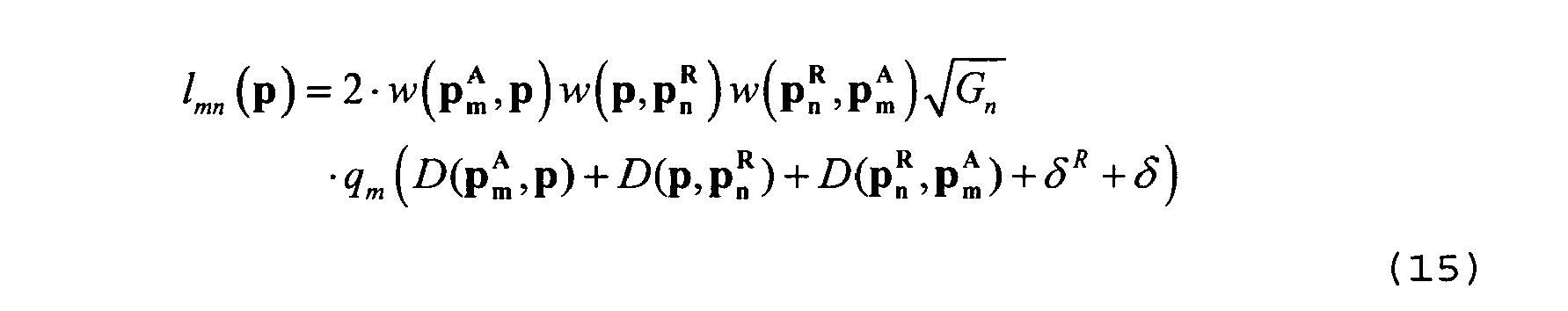
accounts for the signals having travelled along a one-hop path (LOS) either to or from the tag and a two-hop path in the opposite direction and
finally accounts for the signals having travelled along a one-hop path in both directions. - The processing unit maximizes the log-ML function l(p) over the possible values of p. The ML estimate of the position of the tag is then given by:

- By contrast with (10), it should be noted that the maximization need not be carried out with respect to the times at which the anchors respectively transmit the UWB pulse signals, since these times are known by the processing unit.
- If more than one tag is present, each tag k being associated with a unique modulating sequence µ k (t), the expressions (13) to (17) can be calculated for each tag by replacing the correlation functions qm (τ) by:

- Alternatively, each signal rm (t) can be subjected, possibly after de-hopping and/or demodulating, to energy detection within a plurality of consecutive time windows.
- A non-coherent ML approach can be adopted in which the energy pattern is compared to that expected for each candidate tag's position and the position with the best fitting is chosen.
- Alternatively, by comparing the energy values in the consecutive time windows with a threshold, it is possible to determine within rm (t) the time of arrival of the different path components (a path can be NLOS on both ways, NLOS on one way and LOS on the other or LOS on both ways). More specifically, the different path components present in rm (t) are mapped to the possible paths by taking into account the products of the channel gains along these paths. Knowing the delays


- In the second embodiment, reference was made to a passive tag. However, it should be understood that the invention equally applies to any object or a target, in particular to a moving target. In such instance, the man skilled in the art will appreciate that the localization system according to the invention can operate as wireless sensor radar (WSR).
- In the first embodiment as in the second, the invention provides a simple localization method which does not require regenerative or other sophisticated type of relays. The man skilled in the art will understand that the relays play here the role of "virtual anchor nodes", which allows to expand the coverage and to increase the precision of the localization system while keeping the localization system simple and robust.
Claims (17)
- Method for determining the position of an active tag (140) with a radio locating system comprising a plurality of nodes in known positions, referred to as anchor nodes (111, 112), and a plurality of non-regenerative relays (121-123) in known positions, each said relay being adapted to relay a UWB pulse signal emitted by said tag to an anchor node, wherein the signals received by said anchor nodes, either directly from said tag through a LOS path or relayed by a relay through a relayed path, are collected at a processing node (130), said processing node processing the thus collected signals to estimate the position of the tag.
- Method according to claim 1, characterized in that the non-regenerative relays are passive.
- Method according to claim 1, characterized in that the non-regenerative relays are active.
- Method according to claim 1, characterized in that the processing node estimates the position of the node together with the time of emission of the UWB pulse signal by maximizing a log maximum likelihood function depending upon the collected signals.
- Method according to claim 4, characterized in that the log maximum likelihood function is calculated as:

where NA and NR are respectively the number of anchor nodes and the number of relays,


- Method according to any preceding claims, characterized in that the UWB pulse signal is modulated with a time-hopping code and/or a bipolar code.
- Method for determining the position of an object with a radio locating system comprising a plurality of nodes of known positions, referred to as anchor nodes (111,112), and a plurality of non-regenerative relays (121-123) of known positions, each said relay being adapted to relay an interrogating UWB pulse signal emitted from an anchor node to said object and a UWB pulse signal reflected by said object back to said anchor node, wherein the signals received by said anchor nodes after reflection on said object, either through a LOS path or relayed by a relay through a relayed path, are collected at a processing node (130), said processing node processing the thus collected signals to estimate the position of the object.
- Method according to claim 7, characterized in that the object is a passive tag.
- Method according to claim 8, characterized in that the passive tag is adapted to backscatter an incoming signal according to code of binary symbols, a first binary state corresponding to a reflection of the incoming signal as it is and a second binary state corresponding to a reflection of the incoming signal with a reverse polarity.
- Method according to claim 7, characterized in that the non-regenerative relays are passive.
- Method according to claim 7, characterized in that the non-regenerative relays are active.
- Method according to claim 8, characterized in that the processing node estimates the position of the node by maximizing a log maximum likelihood function depending upon the collected signals.
- Method according to claim 12, characterized in that the log maximum likelihood function is calculated as:

with


where NA and NR are respectively the number of anchor nodes and the number of relays;


- Method according to any of claims 7 to 13, characterized in that each anchor node emits a UWB pulse signal which is modulated according to a unique time-hopping and/or bipolar code.
- Radio locating system for estimating the position of an active tag, said radio locating system comprising:- a plurality of nodes of known positions, referred to as anchor nodes (111,112);- a plurality of non-regenerative relays (121-123) of known positions, each said relay being adapted to relay a UWB pulse signal emitted by said tag to an anchor node;- a processing node (130) for collecting the signals received by said anchor nodes, either directly from said tag through a LOS path or relayed by a relay through a relayed path, said processing node being adapted to process the thus collected signals to estimate the position of the tag.
- Radio locating system for estimating the position of an active tag, said radio locating system comprising:- a plurality of nodes of known positions, referred to as anchor nodes (111,112), each anchor node being adapted to emit an interrogating UWB pulse signal;- a plurality of non-regenerative relays (121-123) of known positions, each said relay being adapted to relay an interrogating UWB pulse signal emitted from an anchor node to said object and a UWB pulse signal reflected by said object back to said anchor node;- a processing node (130) adapted to collect the signals received by said anchor nodes after reflection on said object, either through a LOS path or relayed by a relay through a relayed path, said processing node being further adapted to process the thus collected signals to estimate the position of the object.
- Radio locating system according to claim 15 or 16, characterized in that each non-regenerative relay comprises a first antenna (210) and a second antenna (220), a first switch (215) connected to said first antenna and being adapted to switch between the input of a first amplifier (217) and the output of a second amplifier (227), a second switch (225) connected to said second antenna and being adapted to switch between the input of the second amplifier (227) and the output of the first amplifier (217), the first switch and second switch being either simultaneously switched to the respective input and output of the first amplifier, or simultaneously switched to the respective output and input of the second amplifier.
Priority Applications (2)
| Application Number | Priority Date | Filing Date | Title |
|---|---|---|---|
| EP11352013.4A EP2605032B1 (en) | 2011-12-15 | 2011-12-15 | Localization method and system using non-regenerative UWB relays |
| US13/713,950 US9311798B2 (en) | 2011-12-15 | 2012-12-13 | Localization method and system using non-regenerative UWB relays |
Applications Claiming Priority (1)
| Application Number | Priority Date | Filing Date | Title |
|---|---|---|---|
| EP11352013.4A EP2605032B1 (en) | 2011-12-15 | 2011-12-15 | Localization method and system using non-regenerative UWB relays |
Publications (2)
| Publication Number | Publication Date |
|---|---|
| EP2605032A1 true EP2605032A1 (en) | 2013-06-19 |
| EP2605032B1 EP2605032B1 (en) | 2018-03-21 |
Family
ID=45623067
Family Applications (1)
| Application Number | Title | Priority Date | Filing Date |
|---|---|---|---|
| EP11352013.4A Active EP2605032B1 (en) | 2011-12-15 | 2011-12-15 | Localization method and system using non-regenerative UWB relays |
Country Status (2)
| Country | Link |
|---|---|
| US (1) | US9311798B2 (en) |
| EP (1) | EP2605032B1 (en) |
Cited By (3)
| Publication number | Priority date | Publication date | Assignee | Title |
|---|---|---|---|---|
| CN108490391A (en) * | 2018-03-06 | 2018-09-04 | 南京邮电大学 | Based on the new indoor positioning system and localization method for waking up anchor point in turn |
| CN113534044A (en) * | 2021-06-09 | 2021-10-22 | 西安交通大学 | Millimeter wave indoor positioning method and system |
| FR3123458A1 (en) * | 2021-06-01 | 2022-12-02 | Safran Electronics & Defense | Determination of a distance between two devices, in particular for geolocating devices in a network |
Families Citing this family (11)
| Publication number | Priority date | Publication date | Assignee | Title |
|---|---|---|---|---|
| US8587467B1 (en) * | 2010-09-28 | 2013-11-19 | Bae Systems Information And Electronic Systems Integration Inc. | Method and apparatus for determining locations of a moving radar |
| US9413418B2 (en) * | 2012-07-12 | 2016-08-09 | Datalogic Ip Tech S.R.L. | Synchronization of a real-time UWB locating system |
| CN104053229B (en) * | 2013-03-14 | 2018-09-28 | 南京中兴软件有限责任公司 | Mobile terminal, localization method and device |
| FR3016220B1 (en) * | 2014-01-06 | 2017-09-01 | Blinksight | SYSTEM AND METHOD FOR LOCATING AN OBJECT |
| CN108898776B (en) * | 2018-06-29 | 2019-12-06 | 奇点新源国际技术开发(北京)有限公司 | Invader detection method and device applied to perimeter security system |
| US10495737B1 (en) | 2019-02-07 | 2019-12-03 | Clairvoyant Networks, LLC | Methods, systems, and computer readable media for time-slotted ultra-wide-band object tracking |
| US10567035B1 (en) | 2019-03-06 | 2020-02-18 | Clairvoyant Networks, LLC | Methods, systems, and computer readable media for distribution of time synchronization information to ultra-wide-band devices |
| US10484833B1 (en) | 2019-04-12 | 2019-11-19 | Clairvoyant Networks, LLC | Methods, systems and computer readable media for providing and using ultra wideband local area networks (LANs) |
| US11327151B2 (en) * | 2019-06-24 | 2022-05-10 | Nxp B.V. | Ranging technology use for ultra-broadband communication in millimeter wave communication systems |
| CN114205884A (en) * | 2020-09-02 | 2022-03-18 | 华为技术有限公司 | Method for ultra-wideband positioning of electronic devices and ultra-wideband terminal device |
| JP7429331B2 (en) | 2020-10-29 | 2024-02-07 | 浙江吉利控股集団有限公司 | Ultra-wideband based positioning apparatus, method, device and storage medium |
Citations (6)
| Publication number | Priority date | Publication date | Assignee | Title |
|---|---|---|---|---|
| WO2001046711A1 (en) * | 1999-12-22 | 2001-06-28 | Innovative Technology Licensing, Llc | Location position system for relay assisted tracking |
| US20030036374A1 (en) * | 2001-06-04 | 2003-02-20 | Time Domain Corporation | Wireless local area network using impulse radio technology to improve communications between mobile nodes and access points |
| EP1617601A2 (en) * | 2004-04-20 | 2006-01-18 | Universiteit Twente | Distributed precision based localization algorithm for ad-hoc wireless networks |
| FR2924818A1 (en) | 2007-12-06 | 2009-06-12 | Commissariat Energie Atomique | Remote localization system for e.g. military operation, has master node determining difference between free node and master node, and free node and reference node to deduce relative position of free node |
| US20100201573A1 (en) * | 2009-02-06 | 2010-08-12 | Michael George Lamming | Ranging transceiver based activity monitoring system |
| WO2010151829A2 (en) * | 2009-06-26 | 2010-12-29 | Qualcomm Incorporated | Positioning in the presence of passive distributed elements |
Family Cites Families (8)
| Publication number | Priority date | Publication date | Assignee | Title |
|---|---|---|---|---|
| US6081232A (en) * | 1998-07-06 | 2000-06-27 | The United States Of America As Represented By The Secretary Of The Army | Communication relay and a space-fed phased array radar, both utilizing improved mach-zehnder interferometer |
| TWI360317B (en) * | 2003-05-28 | 2012-03-11 | Ericsson Telefon Ab L M | Method and architecture for wireless communication |
| GB2403104B (en) * | 2003-06-16 | 2006-06-14 | Inmarsat Ltd | Communication method and apparatus |
| WO2006015349A2 (en) * | 2004-07-30 | 2006-02-09 | Reva Systems Corporation | Rfid tag data acquisition system |
| US7868760B2 (en) * | 2006-06-05 | 2011-01-11 | Bp Corporation North America Inc. | Method for accounting for people in emergencies in industrial settings |
| US7872581B2 (en) * | 2007-09-28 | 2011-01-18 | Nokia Corporation | Method, devices and system for multiple RFID tag read-out |
| EP2053755A1 (en) * | 2007-10-25 | 2009-04-29 | Commissariat A L'energie Atomique | Method of and apparatus for synchronisation |
| SG173860A1 (en) * | 2009-02-27 | 2011-10-28 | Agency Science Tech & Res | Wireless transmission of layered signals in a relay network |
-
2011
- 2011-12-15 EP EP11352013.4A patent/EP2605032B1/en active Active
-
2012
- 2012-12-13 US US13/713,950 patent/US9311798B2/en active Active
Patent Citations (6)
| Publication number | Priority date | Publication date | Assignee | Title |
|---|---|---|---|---|
| WO2001046711A1 (en) * | 1999-12-22 | 2001-06-28 | Innovative Technology Licensing, Llc | Location position system for relay assisted tracking |
| US20030036374A1 (en) * | 2001-06-04 | 2003-02-20 | Time Domain Corporation | Wireless local area network using impulse radio technology to improve communications between mobile nodes and access points |
| EP1617601A2 (en) * | 2004-04-20 | 2006-01-18 | Universiteit Twente | Distributed precision based localization algorithm for ad-hoc wireless networks |
| FR2924818A1 (en) | 2007-12-06 | 2009-06-12 | Commissariat Energie Atomique | Remote localization system for e.g. military operation, has master node determining difference between free node and master node, and free node and reference node to deduce relative position of free node |
| US20100201573A1 (en) * | 2009-02-06 | 2010-08-12 | Michael George Lamming | Ranging transceiver based activity monitoring system |
| WO2010151829A2 (en) * | 2009-06-26 | 2010-12-29 | Qualcomm Incorporated | Positioning in the presence of passive distributed elements |
Non-Patent Citations (2)
| Title |
|---|
| BENDJABALLAH A ET AL: "Multihop Wireless Communications with non regenerative relays", THE 9TH EUROPEAN CONFERENCE ON WIRELESS TECHNOLOGY, IEEE, PISCATAWAY, NJ, US, 1 September 2006 (2006-09-01), pages 189 - 192, XP031005272, ISBN: 978-2-9600551-5-3 * |
| D. DARDARI ET AL.: "Ranging with ultrawide bandwidth signals in multipath environment", PROC. OF IEEE SPECIAL ISSUE ON UWB TECHNOLOGY & EMERGING APPLICATIONS, vol. 97, no. 2, February 2009 (2009-02-01), pages 404 - 426, XP011253723 |
Cited By (3)
| Publication number | Priority date | Publication date | Assignee | Title |
|---|---|---|---|---|
| CN108490391A (en) * | 2018-03-06 | 2018-09-04 | 南京邮电大学 | Based on the new indoor positioning system and localization method for waking up anchor point in turn |
| FR3123458A1 (en) * | 2021-06-01 | 2022-12-02 | Safran Electronics & Defense | Determination of a distance between two devices, in particular for geolocating devices in a network |
| CN113534044A (en) * | 2021-06-09 | 2021-10-22 | 西安交通大学 | Millimeter wave indoor positioning method and system |
Also Published As
| Publication number | Publication date |
|---|---|
| EP2605032B1 (en) | 2018-03-21 |
| US20130154836A1 (en) | 2013-06-20 |
| US9311798B2 (en) | 2016-04-12 |
Similar Documents
| Publication | Publication Date | Title |
|---|---|---|
| EP2605032B1 (en) | Localization method and system using non-regenerative UWB relays | |
| Ma et al. | Drone relays for battery-free networks | |
| KR101040254B1 (en) | Method and System for Localization Using One-way Ranging Technique | |
| US7962150B2 (en) | Ultra-wideband radios for time-of-flight-ranging and network position estimation | |
| Witrisal et al. | High-accuracy positioning for indoor applications: RFID, UWB, 5G, and beyond | |
| US8259699B2 (en) | Method and system for target positioning and tracking in cooperative relay networks | |
| Röhrig et al. | Indoor location tracking in non-line-of-sight environments using a IEEE 802.15. 4a wireless network | |
| US7304609B2 (en) | Hybrid wireless ranging system and associated methods | |
| US20080204322A1 (en) | Determining Positional Information | |
| CA3023494A1 (en) | Positioning system | |
| US20150323642A1 (en) | Device and method for location of an rfid transmitter | |
| RU2439612C2 (en) | Method of identifying objects using synthetic aperture radar system | |
| AU2007237986A1 (en) | Method and system for retrieving information from wireless sensor nodes | |
| WO2010106747A1 (en) | Positioning system and positioning method | |
| Bonafini et al. | Evaluating indoor and outdoor localization services for LoRaWAN in Smart City applications | |
| KR20090002363A (en) | Intelligent repeater for ultra wide band performance and signal repeating method in its | |
| Smaoui et al. | Single-antenna aoa estimation with uwb radios | |
| CN111246493A (en) | Label-based relay method in environment backscatter communication | |
| Rohrig et al. | Localization of sensor nodes in a wireless sensor network using the nanoLOC TRX transceiver | |
| WO2007067821A2 (en) | Ultra-wideband radios for time-of-flight ranging and network position estimation | |
| Dewberry et al. | Increased ranging capacity using ultrawideband direct-path pulse signal strength with dynamic recalibration | |
| Ivashko et al. | Receivers topology optimization of the combined active and WiFi-based passive radar network | |
| Decarli et al. | Non-regenerative relaying for network localization | |
| US10651889B2 (en) | Method and device for the detection of a pulse of a signal | |
| Dardari et al. | Enhanced localization coverage with non-regenerative UWB relays |
Legal Events
| Date | Code | Title | Description |
|---|---|---|---|
| PUAI | Public reference made under article 153(3) epc to a published international application that has entered the european phase |
Free format text: ORIGINAL CODE: 0009012 |
|
| AK | Designated contracting states |
Kind code of ref document: A1 Designated state(s): AL AT BE BG CH CY CZ DE DK EE ES FI FR GB GR HR HU IE IS IT LI LT LU LV MC MK MT NL NO PL PT RO RS SE SI SK SM TR |
|
| AX | Request for extension of the european patent |
Extension state: BA ME |
|
| 17P | Request for examination filed |
Effective date: 20131216 |
|
| RBV | Designated contracting states (corrected) |
Designated state(s): AL AT BE BG CH CY CZ DE DK EE ES FI FR GB GR HR HU IE IS IT LI LT LU LV MC MK MT NL NO PL PT RO RS SE SI SK SM TR |
|
| 17Q | First examination report despatched |
Effective date: 20160610 |
|
| RIC1 | Information provided on ipc code assigned before grant |
Ipc: G08B 13/24 20060101ALI20170901BHEP Ipc: G01S 5/02 20100101AFI20170901BHEP |
|
| GRAP | Despatch of communication of intention to grant a patent |
Free format text: ORIGINAL CODE: EPIDOSNIGR1 |
|
| INTG | Intention to grant announced |
Effective date: 20171024 |
|
| GRAS | Grant fee paid |
Free format text: ORIGINAL CODE: EPIDOSNIGR3 |
|
| GRAA | (expected) grant |
Free format text: ORIGINAL CODE: 0009210 |
|
| AK | Designated contracting states |
Kind code of ref document: B1 Designated state(s): AL AT BE BG CH CY CZ DE DK EE ES FI FR GB GR HR HU IE IS IT LI LT LU LV MC MK MT NL NO PL PT RO RS SE SI SK SM TR |
|
| REG | Reference to a national code |
Ref country code: GB Ref legal event code: FG4D |
|
| REG | Reference to a national code |
Ref country code: CH Ref legal event code: EP |
|
| REG | Reference to a national code |
Ref country code: AT Ref legal event code: REF Ref document number: 981696 Country of ref document: AT Kind code of ref document: T Effective date: 20180415 |
|
| REG | Reference to a national code |
Ref country code: IE Ref legal event code: FG4D |
|
| REG | Reference to a national code |
Ref country code: DE Ref legal event code: R096 Ref document number: 602011046656 Country of ref document: DE |
|
| REG | Reference to a national code |
Ref country code: NL Ref legal event code: MP Effective date: 20180321 |
|
| PG25 | Lapsed in a contracting state [announced via postgrant information from national office to epo] |
Ref country code: CY Free format text: LAPSE BECAUSE OF FAILURE TO SUBMIT A TRANSLATION OF THE DESCRIPTION OR TO PAY THE FEE WITHIN THE PRESCRIBED TIME-LIMIT Effective date: 20180321 Ref country code: HR Free format text: LAPSE BECAUSE OF FAILURE TO SUBMIT A TRANSLATION OF THE DESCRIPTION OR TO PAY THE FEE WITHIN THE PRESCRIBED TIME-LIMIT Effective date: 20180321 Ref country code: LT Free format text: LAPSE BECAUSE OF FAILURE TO SUBMIT A TRANSLATION OF THE DESCRIPTION OR TO PAY THE FEE WITHIN THE PRESCRIBED TIME-LIMIT Effective date: 20180321 Ref country code: FI Free format text: LAPSE BECAUSE OF FAILURE TO SUBMIT A TRANSLATION OF THE DESCRIPTION OR TO PAY THE FEE WITHIN THE PRESCRIBED TIME-LIMIT Effective date: 20180321 Ref country code: NO Free format text: LAPSE BECAUSE OF FAILURE TO SUBMIT A TRANSLATION OF THE DESCRIPTION OR TO PAY THE FEE WITHIN THE PRESCRIBED TIME-LIMIT Effective date: 20180621 |
|
| REG | Reference to a national code |
Ref country code: LT Ref legal event code: MG4D |
|
| REG | Reference to a national code |
Ref country code: AT Ref legal event code: MK05 Ref document number: 981696 Country of ref document: AT Kind code of ref document: T Effective date: 20180321 |
|
| PG25 | Lapsed in a contracting state [announced via postgrant information from national office to epo] |
Ref country code: BG Free format text: LAPSE BECAUSE OF FAILURE TO SUBMIT A TRANSLATION OF THE DESCRIPTION OR TO PAY THE FEE WITHIN THE PRESCRIBED TIME-LIMIT Effective date: 20180621 Ref country code: LV Free format text: LAPSE BECAUSE OF FAILURE TO SUBMIT A TRANSLATION OF THE DESCRIPTION OR TO PAY THE FEE WITHIN THE PRESCRIBED TIME-LIMIT Effective date: 20180321 Ref country code: SE Free format text: LAPSE BECAUSE OF FAILURE TO SUBMIT A TRANSLATION OF THE DESCRIPTION OR TO PAY THE FEE WITHIN THE PRESCRIBED TIME-LIMIT Effective date: 20180321 Ref country code: RS Free format text: LAPSE BECAUSE OF FAILURE TO SUBMIT A TRANSLATION OF THE DESCRIPTION OR TO PAY THE FEE WITHIN THE PRESCRIBED TIME-LIMIT Effective date: 20180321 Ref country code: GR Free format text: LAPSE BECAUSE OF FAILURE TO SUBMIT A TRANSLATION OF THE DESCRIPTION OR TO PAY THE FEE WITHIN THE PRESCRIBED TIME-LIMIT Effective date: 20180622 |
|
| PG25 | Lapsed in a contracting state [announced via postgrant information from national office to epo] |
Ref country code: EE Free format text: LAPSE BECAUSE OF FAILURE TO SUBMIT A TRANSLATION OF THE DESCRIPTION OR TO PAY THE FEE WITHIN THE PRESCRIBED TIME-LIMIT Effective date: 20180321 Ref country code: NL Free format text: LAPSE BECAUSE OF FAILURE TO SUBMIT A TRANSLATION OF THE DESCRIPTION OR TO PAY THE FEE WITHIN THE PRESCRIBED TIME-LIMIT Effective date: 20180321 Ref country code: PL Free format text: LAPSE BECAUSE OF FAILURE TO SUBMIT A TRANSLATION OF THE DESCRIPTION OR TO PAY THE FEE WITHIN THE PRESCRIBED TIME-LIMIT Effective date: 20180321 Ref country code: RO Free format text: LAPSE BECAUSE OF FAILURE TO SUBMIT A TRANSLATION OF THE DESCRIPTION OR TO PAY THE FEE WITHIN THE PRESCRIBED TIME-LIMIT Effective date: 20180321 Ref country code: ES Free format text: LAPSE BECAUSE OF FAILURE TO SUBMIT A TRANSLATION OF THE DESCRIPTION OR TO PAY THE FEE WITHIN THE PRESCRIBED TIME-LIMIT Effective date: 20180321 Ref country code: AL Free format text: LAPSE BECAUSE OF FAILURE TO SUBMIT A TRANSLATION OF THE DESCRIPTION OR TO PAY THE FEE WITHIN THE PRESCRIBED TIME-LIMIT Effective date: 20180321 |
|
| PG25 | Lapsed in a contracting state [announced via postgrant information from national office to epo] |
Ref country code: AT Free format text: LAPSE BECAUSE OF FAILURE TO SUBMIT A TRANSLATION OF THE DESCRIPTION OR TO PAY THE FEE WITHIN THE PRESCRIBED TIME-LIMIT Effective date: 20180321 Ref country code: SM Free format text: LAPSE BECAUSE OF FAILURE TO SUBMIT A TRANSLATION OF THE DESCRIPTION OR TO PAY THE FEE WITHIN THE PRESCRIBED TIME-LIMIT Effective date: 20180321 Ref country code: SK Free format text: LAPSE BECAUSE OF FAILURE TO SUBMIT A TRANSLATION OF THE DESCRIPTION OR TO PAY THE FEE WITHIN THE PRESCRIBED TIME-LIMIT Effective date: 20180321 Ref country code: CZ Free format text: LAPSE BECAUSE OF FAILURE TO SUBMIT A TRANSLATION OF THE DESCRIPTION OR TO PAY THE FEE WITHIN THE PRESCRIBED TIME-LIMIT Effective date: 20180321 |
|
| PG25 | Lapsed in a contracting state [announced via postgrant information from national office to epo] |
Ref country code: PT Free format text: LAPSE BECAUSE OF FAILURE TO SUBMIT A TRANSLATION OF THE DESCRIPTION OR TO PAY THE FEE WITHIN THE PRESCRIBED TIME-LIMIT Effective date: 20180723 |
|
| REG | Reference to a national code |
Ref country code: DE Ref legal event code: R097 Ref document number: 602011046656 Country of ref document: DE |
|
| PLBE | No opposition filed within time limit |
Free format text: ORIGINAL CODE: 0009261 |
|
| STAA | Information on the status of an ep patent application or granted ep patent |
Free format text: STATUS: NO OPPOSITION FILED WITHIN TIME LIMIT |
|
| PG25 | Lapsed in a contracting state [announced via postgrant information from national office to epo] |
Ref country code: DK Free format text: LAPSE BECAUSE OF FAILURE TO SUBMIT A TRANSLATION OF THE DESCRIPTION OR TO PAY THE FEE WITHIN THE PRESCRIBED TIME-LIMIT Effective date: 20180321 |
|
| 26N | No opposition filed |
Effective date: 20190102 |
|
| PG25 | Lapsed in a contracting state [announced via postgrant information from national office to epo] |
Ref country code: SI Free format text: LAPSE BECAUSE OF FAILURE TO SUBMIT A TRANSLATION OF THE DESCRIPTION OR TO PAY THE FEE WITHIN THE PRESCRIBED TIME-LIMIT Effective date: 20180321 |
|
| REG | Reference to a national code |
Ref country code: CH Ref legal event code: PL |
|
| PG25 | Lapsed in a contracting state [announced via postgrant information from national office to epo] |
Ref country code: LU Free format text: LAPSE BECAUSE OF NON-PAYMENT OF DUE FEES Effective date: 20181215 Ref country code: MC Free format text: LAPSE BECAUSE OF FAILURE TO SUBMIT A TRANSLATION OF THE DESCRIPTION OR TO PAY THE FEE WITHIN THE PRESCRIBED TIME-LIMIT Effective date: 20180321 |
|
| REG | Reference to a national code |
Ref country code: IE Ref legal event code: MM4A |
|
| REG | Reference to a national code |
Ref country code: BE Ref legal event code: MM Effective date: 20181231 |
|
| PG25 | Lapsed in a contracting state [announced via postgrant information from national office to epo] |
Ref country code: IE Free format text: LAPSE BECAUSE OF NON-PAYMENT OF DUE FEES Effective date: 20181215 |
|
| PG25 | Lapsed in a contracting state [announced via postgrant information from national office to epo] |
Ref country code: BE Free format text: LAPSE BECAUSE OF NON-PAYMENT OF DUE FEES Effective date: 20181231 |
|
| PG25 | Lapsed in a contracting state [announced via postgrant information from national office to epo] |
Ref country code: LI Free format text: LAPSE BECAUSE OF NON-PAYMENT OF DUE FEES Effective date: 20181231 Ref country code: CH Free format text: LAPSE BECAUSE OF NON-PAYMENT OF DUE FEES Effective date: 20181231 |
|
| PG25 | Lapsed in a contracting state [announced via postgrant information from national office to epo] |
Ref country code: MT Free format text: LAPSE BECAUSE OF NON-PAYMENT OF DUE FEES Effective date: 20181215 |
|
| PG25 | Lapsed in a contracting state [announced via postgrant information from national office to epo] |
Ref country code: TR Free format text: LAPSE BECAUSE OF FAILURE TO SUBMIT A TRANSLATION OF THE DESCRIPTION OR TO PAY THE FEE WITHIN THE PRESCRIBED TIME-LIMIT Effective date: 20180321 |
|
| PG25 | Lapsed in a contracting state [announced via postgrant information from national office to epo] |
Ref country code: HU Free format text: LAPSE BECAUSE OF FAILURE TO SUBMIT A TRANSLATION OF THE DESCRIPTION OR TO PAY THE FEE WITHIN THE PRESCRIBED TIME-LIMIT; INVALID AB INITIO Effective date: 20111215 Ref country code: MK Free format text: LAPSE BECAUSE OF NON-PAYMENT OF DUE FEES Effective date: 20180321 |
|
| PG25 | Lapsed in a contracting state [announced via postgrant information from national office to epo] |
Ref country code: IS Free format text: LAPSE BECAUSE OF FAILURE TO SUBMIT A TRANSLATION OF THE DESCRIPTION OR TO PAY THE FEE WITHIN THE PRESCRIBED TIME-LIMIT Effective date: 20180721 |
|
| PGFP | Annual fee paid to national office [announced via postgrant information from national office to epo] |
Ref country code: IT Payment date: 20221230 Year of fee payment: 12 |
|
| PGFP | Annual fee paid to national office [announced via postgrant information from national office to epo] |
Ref country code: GB Payment date: 20231221 Year of fee payment: 13 |
|
| PGFP | Annual fee paid to national office [announced via postgrant information from national office to epo] |
Ref country code: FR Payment date: 20231221 Year of fee payment: 13 Ref country code: DE Payment date: 20231219 Year of fee payment: 13 |