EP2608201A2 - Signal processing apparatus and signal processing method - Google Patents
Signal processing apparatus and signal processing method Download PDFInfo
- Publication number
- EP2608201A2 EP2608201A2 EP12194568.7A EP12194568A EP2608201A2 EP 2608201 A2 EP2608201 A2 EP 2608201A2 EP 12194568 A EP12194568 A EP 12194568A EP 2608201 A2 EP2608201 A2 EP 2608201A2
- Authority
- EP
- European Patent Office
- Prior art keywords
- input signals
- value
- signal processing
- calculates
- processing apparatus
- Prior art date
- Legal status (The legal status is an assumption and is not a legal conclusion. Google has not performed a legal analysis and makes no representation as to the accuracy of the status listed.)
- Granted
Links
- 238000003672 processing method Methods 0.000 title claims description 3
- 238000000034 method Methods 0.000 claims description 43
- 230000001629 suppression Effects 0.000 claims description 21
- 230000003111 delayed effect Effects 0.000 claims 2
- 230000001934 delay Effects 0.000 claims 1
- 238000010586 diagram Methods 0.000 description 15
- 230000000694 effects Effects 0.000 description 6
- 238000005070 sampling Methods 0.000 description 6
- 230000001360 synchronised effect Effects 0.000 description 3
- 238000007664 blowing Methods 0.000 description 2
- 238000007796 conventional method Methods 0.000 description 2
- PIRWNASAJNPKHT-SHZATDIYSA-N pamp Chemical compound C([C@@H](C(=O)N[C@@H](CCCNC(N)=N)C(=O)N[C@@H](CCCCN)C(=O)N[C@@H](CCCCN)C(=O)N[C@@H](CC=1C2=CC=CC=C2NC=1)C(=O)N[C@@H](CC(N)=O)C(=O)N[C@@H](CCCCN)C(=O)N[C@@H](CC=1C2=CC=CC=C2NC=1)C(=O)N[C@@H](C)C(=O)N[C@@H](CC(C)C)C(=O)N[C@@H](CO)C(=O)N[C@@H](CCCNC(N)=N)C(N)=O)NC(=O)[C@H](CCC(O)=O)NC(=O)[C@H](CO)NC(=O)[C@H](C)NC(=O)[C@@H](NC(=O)[C@H](CC(O)=O)NC(=O)[C@H](CC(C)C)NC(=O)[C@H](CCCNC(N)=N)NC(=O)[C@H](C)N)C(C)C)C1=CC=CC=C1 PIRWNASAJNPKHT-SHZATDIYSA-N 0.000 description 2
- NAWXUBYGYWOOIX-SFHVURJKSA-N (2s)-2-[[4-[2-(2,4-diaminoquinazolin-6-yl)ethyl]benzoyl]amino]-4-methylidenepentanedioic acid Chemical compound C1=CC2=NC(N)=NC(N)=C2C=C1CCC1=CC=C(C(=O)N[C@@H](CC(=C)C(O)=O)C(O)=O)C=C1 NAWXUBYGYWOOIX-SFHVURJKSA-N 0.000 description 1
- 238000004458 analytical method Methods 0.000 description 1
- 230000001788 irregular Effects 0.000 description 1
Images


Classifications
-
- H—ELECTRICITY
- H04—ELECTRIC COMMUNICATION TECHNIQUE
- H04R—LOUDSPEAKERS, MICROPHONES, GRAMOPHONE PICK-UPS OR LIKE ACOUSTIC ELECTROMECHANICAL TRANSDUCERS; DEAF-AID SETS; PUBLIC ADDRESS SYSTEMS
- H04R3/00—Circuits for transducers, loudspeakers or microphones
- H04R3/005—Circuits for transducers, loudspeakers or microphones for combining the signals of two or more microphones
-
- G—PHYSICS
- G10—MUSICAL INSTRUMENTS; ACOUSTICS
- G10L—SPEECH ANALYSIS OR SYNTHESIS; SPEECH RECOGNITION; SPEECH OR VOICE PROCESSING; SPEECH OR AUDIO CODING OR DECODING
- G10L25/00—Speech or voice analysis techniques not restricted to a single one of groups G10L15/00 - G10L21/00
- G10L25/78—Detection of presence or absence of voice signals
- G10L25/84—Detection of presence or absence of voice signals for discriminating voice from noise
-
- H—ELECTRICITY
- H04—ELECTRIC COMMUNICATION TECHNIQUE
- H04B—TRANSMISSION
- H04B15/00—Suppression or limitation of noise or interference
-
- H—ELECTRICITY
- H04—ELECTRIC COMMUNICATION TECHNIQUE
- H04R—LOUDSPEAKERS, MICROPHONES, GRAMOPHONE PICK-UPS OR LIKE ACOUSTIC ELECTROMECHANICAL TRANSDUCERS; DEAF-AID SETS; PUBLIC ADDRESS SYSTEMS
- H04R1/00—Details of transducers, loudspeakers or microphones
- H04R1/20—Arrangements for obtaining desired frequency or directional characteristics
- H04R1/32—Arrangements for obtaining desired frequency or directional characteristics for obtaining desired directional characteristic only
- H04R1/40—Arrangements for obtaining desired frequency or directional characteristics for obtaining desired directional characteristic only by combining a number of identical transducers
- H04R1/406—Arrangements for obtaining desired frequency or directional characteristics for obtaining desired directional characteristic only by combining a number of identical transducers microphones
-
- G—PHYSICS
- G10—MUSICAL INSTRUMENTS; ACOUSTICS
- G10L—SPEECH ANALYSIS OR SYNTHESIS; SPEECH RECOGNITION; SPEECH OR VOICE PROCESSING; SPEECH OR AUDIO CODING OR DECODING
- G10L21/00—Processing of the speech or voice signal to produce another audible or non-audible signal, e.g. visual or tactile, in order to modify its quality or its intelligibility
- G10L21/02—Speech enhancement, e.g. noise reduction or echo cancellation
- G10L21/0208—Noise filtering
- G10L21/0216—Noise filtering characterised by the method used for estimating noise
- G10L2021/02168—Noise filtering characterised by the method used for estimating noise the estimation exclusively taking place during speech pauses
-
- H—ELECTRICITY
- H04—ELECTRIC COMMUNICATION TECHNIQUE
- H04R—LOUDSPEAKERS, MICROPHONES, GRAMOPHONE PICK-UPS OR LIKE ACOUSTIC ELECTROMECHANICAL TRANSDUCERS; DEAF-AID SETS; PUBLIC ADDRESS SYSTEMS
- H04R2201/00—Details of transducers, loudspeakers or microphones covered by H04R1/00 but not provided for in any of its subgroups
- H04R2201/40—Details of arrangements for obtaining desired directional characteristic by combining a number of identical transducers covered by H04R1/40 but not provided for in any of its subgroups
- H04R2201/403—Linear arrays of transducers
-
- H—ELECTRICITY
- H04—ELECTRIC COMMUNICATION TECHNIQUE
- H04R—LOUDSPEAKERS, MICROPHONES, GRAMOPHONE PICK-UPS OR LIKE ACOUSTIC ELECTROMECHANICAL TRANSDUCERS; DEAF-AID SETS; PUBLIC ADDRESS SYSTEMS
- H04R2410/00—Microphones
- H04R2410/07—Mechanical or electrical reduction of wind noise generated by wind passing a microphone
-
- H—ELECTRICITY
- H04—ELECTRIC COMMUNICATION TECHNIQUE
- H04R—LOUDSPEAKERS, MICROPHONES, GRAMOPHONE PICK-UPS OR LIKE ACOUSTIC ELECTROMECHANICAL TRANSDUCERS; DEAF-AID SETS; PUBLIC ADDRESS SYSTEMS
- H04R2430/00—Signal processing covered by H04R, not provided for in its groups
- H04R2430/20—Processing of the output signals of the acoustic transducers of an array for obtaining a desired directivity characteristic
-
- H—ELECTRICITY
- H04—ELECTRIC COMMUNICATION TECHNIQUE
- H04R—LOUDSPEAKERS, MICROPHONES, GRAMOPHONE PICK-UPS OR LIKE ACOUSTIC ELECTROMECHANICAL TRANSDUCERS; DEAF-AID SETS; PUBLIC ADDRESS SYSTEMS
- H04R2499/00—Aspects covered by H04R or H04S not otherwise provided for in their subgroups
- H04R2499/10—General applications
- H04R2499/11—Transducers incorporated or for use in hand-held devices, e.g. mobile phones, PDA's, camera's
Definitions
- FIG. 10 is a diagram illustrating an example of the conventional apparatus. As illustrated in FIG. 10 , a conventional apparatus 10 is connected to microphones 10a and 10b. The microphones 10a and 10b are spaced apart from each other by a predetermined distance.
- the conventional apparatus 10 includes a correlation analyzer 11, a noise analyzer 12, and a noise reduction unit 13.
- the microphone 10a is a microphone which converts collected sound into an input signal Lin(t) and outputs the input signal Lin(t) to the conventional apparatus 10.
- the microphone 10b is a microphone which converts collected sound into an input signal Rin(t) and outputs the input signal Rin(t) to the conventional apparatus 10.
- t corresponds to a sampling number of the input signal.
- the correlation analyzer 11 calculates a correlation value r(t) between the input signal Lin(t) and the input signal Rin(t) by using the formula (1).
- the correlation analyzer 11 sequentially changes the value of i from 1 to n and calculates a correlation value r(t). For example, the value of n is 128.
- the correlation analyzer 11 outputs the correlation value r(t) to the noise analyzer 12.
- r t ⁇ Lin ⁇ t - i ⁇ Rin ⁇ t - i / ⁇ Lin ⁇ t - i 2 1 / 2 ⁇ ⁇ Rin ⁇ t - i 2 1 / 2
- the noise analyzer 12 determines that there is noise of wind and outputs control information to turn down volume to the noise reduction unit 13.
- the noise reduction unit 13 adjusts the volumes of the input signals Lin(t) and Rin(t) and outputs the input signals Lin(t) and Rin(t) to an external apparatus. For example, when the noise reduction unit 13 receives the control information to turn down volume, the noise reduction unit 13 turns down the volumes of the input signals Lin(t) and Rin(t) and outputs the input signals Lin(t) and Rin(t) to the external apparatus.
- a signal processing apparatus includes: an adder that acquires a plurality of input signals from a plurality of microphones and calculates an added value obtained by adding the input signals together; a subtracter that acquires a plurality of input signals from the plurality of microphones and calculates a subtracted value obtained by subtracting one input signal from the other input signal; and a determination unit that determines whether noise is included in the input signals based on the added value and the subtracted value.
- FIG. 1 is a diagram illustrating a configuration of a signal processing apparatus according to a first embodiment. As illustrated in FIG. 1 , a signal processing apparatus 100 is connected to microphones 10a and 10b. The microphones 10a and 10b are spaced apart from each other by a predetermined distance.
- the signal processing apparatus 100 includes an adder 110, a subtracter 120, and power calculators 130a and 130b.
- the signal processing apparatus 100 also includes a ratio calculator 140, a determination unit 150, a gain calculator 160, and a noise suppression unit 170.
- the microphone 10a is a microphone which converts collected sound into an input signal Lin(t) and outputs the input signal Lin(t) to the signal processing apparatus 100.
- the microphone 10b is a microphone which converts collected sound into an input signal Rin(t) and outputs the input signal Rin(t) to the signal processing apparatus 100.
- t corresponds to a sampling number of the input signal.
- the adder 110 calculates an added value p(t) by adding the input signal Lin(t) and the input signal Rin(t) together.
- the added value p(t) is represented by the formula (2).
- the adder 110 outputs the added value p(t) to the power calculator 130a.
- p t Lin t + Rin t
- the subtracter 120 calculates an subtracted value m(t) by subtracting the input signal Rin(t) from the input signal Lin(t).
- the subtracted value m(t) is represented by the formula (3).
- the subtracter 120 outputs the subtracted value m(t) to the power calculator 130b.
- m t Lin t - Rin t
- the power calculator 130a calculates a power Ppow(t) by summing up squared values of the added value p(t) of different sampling numbers.
- the power Ppow(t) is represented by the formula (4).
- the power calculator 130a sequentially changes the value of j from 1 to n and calculates the power Ppow(t).
- the value of n is a natural number. For example, the value of n is 128.
- the power calculator 130a outputs the power Ppow(t) to the ratio calculator 140.
- Ppow t ⁇ p t - j 2
- the power calculator 130b calculates a power Mpow(t) by summing up squared values of the subtracted value m(t) of different sampling numbers.
- the power Mpow(t) is represented by the formula (5).
- the power calculator 130b sequentially changes the value of j from 1 to n and calculates the power Mpow(t).
- the value of n is a natural number. For example, the value of n is 128.
- the power calculator 130b outputs the power Mpow(t) to the ratio calculator 140.
- Mpow t ⁇ m t - j 2
- the ratio calculator 140 calculates a ratio v(t) of the power Ppow(t) and the power Mpow(t). For example, the ratio calculator 140 calculates the ratio v(t) by the formula (6). The ratio calculator 140 outputs the ratio v(t) to the determination unit 150 and the gain calculator 160.
- v(t) may be a square root of the ratio of the power Ppow(t) and the power Mpow(t).
- v t Mpow t / Ppow t
- the determination unit 150 determines whether noise is included in the input signals Lin(t) and Rin(t) based on the ratio v(t). When the value of the ratio v(t) is greater than or equal to a predetermined threshold value, the determination unit 150 determines that noise is included in the input signals Lin(t) and Rin(t). The determination unit 150 outputs a determination result to the gain calculator 160.
- the gain calculator 160 calculates a gain based on the ratio v(t).
- the gain calculator 160 first calculates g'(t) by the formula (7) and thereafter calculates a gain g(t) by the formula (8).
- ⁇ is a lower limit value greater than or equal to 0 and smaller than or equal to 1.
- the gain calculator 160 calculates g'(t) and thereafter calculates the larger value of g'(t) and ⁇ as the gain g(t).
- the gain calculator 160 outputs the gain g(t) to the noise suppression unit 170.
- the gain calculator 160 may calculate the gain g(t) when noise is included in the input signals Lin(t) and Rin(t) based on the determination result of the determination unit 150. On the other hand, when noise is not included in the input signals Lin(t) and Rin(t), the gain calculator 160 may set 1 to the gain g(t) and output the gain g(t) to the noise suppression unit 170.
- the noise suppression unit 170 suppresses noise by multiplying the input signals Lin(t) and Rin(t) by the gain g(t). For example, the noise suppression unit 170 generates output signals Lout(t) and Rout(t) from the input signals Lin(t) and Rin(t) and outputs the generated signals to an external apparatus.
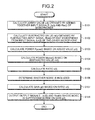
- FIG. 2 is a flowchart illustrating a processing procedure of the signal processing apparatus according to the first embodiment.
- the process illustrated in FIG. 2 is performed when input signals are received from the microphones 10a and 10b.
- the signal processing apparatus 100 calculates the added value p(t) obtained by adding together the input signals Lin(t) and Rin(t) of the microphones 10a and 10b (step S101).
- the signal processing apparatus 100 calculates the subtracted value m(t) obtained by subtracting the input signal Rin(t) of one microphone 10b from the input signal Lin(t) of the other microphone 10a (step S102).
- the signal processing apparatus 100 calculates the power Ppow(t) based on the added value p(t) (step S103).
- the signal processing apparatus 100 calculates the power Mpow(t) based on the subtracted value m(t) (step S104).
- the signal processing apparatus 100 calculates the ratio v(t) (step S105) and determines whether noise is included (step S106).
- the signal processing apparatus 100 calculates the gain g(t) based on the ratio v(t) (step S107).
- the signal processing apparatus 100 outputs the output signals Lout(t) and Rout(t) whose noise is suppressed based on the gain g(t) (step S108).
- the determination unit 150 determines whether noise is included in the input signals Lin(t) and Rin(t) based on the added value p(t) calculated by the adder 110 and the subtracted value m(t) calculated by the subtracter 120. Therefore, it is possible to accurately determine whether noise is included, so that noise included in the input signals can be sufficiently suppressed by using the determination result.
- the lower the frequency the stronger the correlation between the input signals. This is because the lower the frequency, the smaller the variation of waveforms in the time axis direction, so that the waveforms have similar shapes.
- An extreme example is a direct current. Therefore, in order to strengthen the correlation, the adder 110 sums up the input signals. On the other hand, in order to suppress the correlation, the subtracter 120 subtracts one input signal from the other input signal.
- noise can be accurately detected by using the ratio of the "power of (Lin(t)-Rin(t))" based on the “power of (Lin(t)+Rin(t))". Also, an appropriate gain can be calculated by using the ratio of the "power of (Lin(t)-Rin(t))” based on the “power of (Lin(t)+Rin(t))", and a noise component included in the input signals can be suppressed by using the gain.
- FIG. 3 is a diagram for explaining an effect of the present invention compared with a conventional apparatus.
- Signals 20A in FIG. 3 indicates a relationship between the sampling number and the gain g(t) of the conventional apparatus.
- Signals 208 in FIG. 3 indicates a relationship between the sampling number and the gain g(t) of the signal processing apparatus 100.
- Sections 21 in the signals 20A and 20B are sections including voice. When comparing the signals 20A and 20B, in the signals 20B, the gain g(t) in sections including only wind hitting noise is reduced while the gain g(t) in the sections 21 is substantially maintained at 1. Therefore, in the present invention, it is possible to turn down volume of a part of input signals including noise without turning down volume of whole input signals in voice sections.
- the determination unit 150 determines whether noise is included based on the value of the ratio v(t). However, it is not limited to this.
- the determination unit 150 may obtain a difference between the Ppow(t) and the Mpow(t), and when the difference value is smaller than a predetermined threshold value, the determination unit 150 may determine that noise is included in the input signals.
- the signal processing apparatus 100 may be configured by integrating the determination unit 150 and the gain calculator 160 together.
- FIG. 4 is a diagram illustrating a configuration of the signal processing apparatus according to the second embodiment.
- a signal processing apparatus 200 is connected to the microphones 10a and 10b.
- the microphones 10a and 10b are spaced apart from each other by a predetermined distance.
- the description about the microphones 10a and 10b is the same as that in the first embodiment.
- the signal processing apparatus 200 includes a delay detector 201 and delay devices 202a and 202b.
- the signal processing apparatus 200 also includes an adder 210, a subtracter 220, and power calculators 230a and 230b.
- the signal processing apparatus 200 also includes a ratio calculator 240, a determination unit 250, a gain calculator 260, and a noise suppression unit 270.
- the delay detector 201 calculates a correlation coefficient c(d) between the input signal Lin(t) and the input signal Rin(t) by the formula (13).
- the delay detector 201 changes a delay amount d and detects a delay amount dmax by which the value of correlation coefficient c(d) is the maximum.
- c d ⁇ Lin t ⁇ Rin ⁇ t - d / ⁇ Lin ⁇ t 2 1 / 2 ⁇ ⁇ Rin ⁇ t - d 2 1 / 2
- the delay detector 201 calculates a delay amount dL applied to the input signal from the microphone 10a and a delay amount dR applied to the input signal from the microphone 10b in order to synchronize the input signals inputted from the microphones 10a and 10b.
- a delay amount dL applied to the input signal from the microphone 10a and a delay amount dR applied to the input signal from the microphone 10b is calculated below.
- the delay detector 201 sets the value of dL to 0 and sets the value of dR to the value of the dmax. Then, the delay detector 201 outputs the dL to the delay device 202a and outputs the dR to the delay device 202b.
- the delay detector 201 sets the value of dL to the absolute value of the dmax and sets the value of dR to 0. Then, the delay detector 201 outputs the dL to the delay device 202a and outputs the dR to the delay device 202b.
- the delay device 202a performs a delay process of the input signal Lin(t) from the microphone 10a.
- the delay device 202a outputs an input signal Lin(t-dL) obtained by performing a delay process on the input signal Lin(t) to the adder 210 and the subtracter 220.
- the delay device 202b performs a delay process of the input signal Rin(t) from the microphone 10b.
- the delay device 202b outputs an input signal Rin(t-dR) obtained by performing a delay process on the input signal Rin(t) to the adder 210 and the subtracter 220.
- the adder 210 calculates an added value p(t) by adding together the input signals Lin(t-dL) and Rin(t-dR) whose delay amounts are adjusted.
- the adder 210 outputs the added value p(t) to the power calculator 230a.
- the subtracter 220 calculates an subtracted value m(t) by subtracting the input signal Rin(t-dR) from the input signal Lin(t-dL).
- the subtracter 220 outputs the subtracted value m(t) to the power calculator 230b.
- the descriptions about the power calculators 230a and 230b, the ratio calculator 240, the determination unit 250, the gain calculator 260, and the noise suppression unit 270 are the same as those of the power calculators 130a and 130b, the ratio calculator 140, the determination unit 150, the gain calculator 160, and the noise suppression unit 170 illustrated in FIG. 1 .
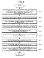
- FIG. 5 is a flowchart illustrating the processing procedure of the signal processing apparatus according to the second embodiment.
- the process illustrated in FIG. 5 is performed when input signals are received from the microphones 10a and 10b.
- the signal processing apparatus 200 detects the maximum value of the correlation coefficient c(d) between the input signal Lin(t) and the input signal Rin(t) and calculates the delay amounts dL and dR for synchronization (step S201).
- the signal processing apparatus 200 calculates the p(t) by performing synchronous addition (step S202) and calculates the m(t) by performing synchronous subtraction (step S203).
- the signal processing apparatus 200 calculates the power Ppow(t) based on the added value p(t) (step S204).
- the signal processing apparatus 200 calculates the power Mpow(t) based on the subtracted value m(t) (step S205).
- the signal processing apparatus 200 calculates the ratio v(t) (step S206) and determines whether noise is included (step S207).
- the signal processing apparatus 200 calculates the gain g(t) based on the ratio v(t) (step S208).
- the signal processing apparatus 200 outputs the output signals Lout(t) and Rout(t) whose noise is suppressed based on the gain g(t) (step S209).
- the delay detector 201 calculates the delay amounts dL and dR and the delay devices 202a and 202b synchronize the input signals.
- the determination unit 250 determines whether noise is included in the input signals Lin(t) and Rin(t) based on the added value p(t) calculated by the adder 210 and the subtracted value m(t) calculated by the subtracter 220. Therefore, even if the timings when voice of a user is collected by the microphones 10a and 10b are different from each other, the input signals can be synchronized by adjusting the delay amounts. Thus, it is possible to accurately determine whether noise is included in a direction of a user whose voice is desired to be recorded, so that noise included in the input signals can be suppressed by using the determination result.
- FIG. 6 is a diagram illustrating a configuration of the signal processing apparatus according to the third embodiment.
- a signal processing apparatus 300 is connected to the microphones 10a and 10b.
- the microphones 10a and 10b are spaced apart from each other by a predetermined distance.
- the description about the microphones 10a and 10b is the same as that in the first embodiment.
- the signal processing apparatus 300 includes FFTs (Fast Fourier Transforms) 301a and 301b, an adder 310, a subtracter 320, and power calculators 330a and 330b.
- the signal processing apparatus 300 also includes a ratio calculator 340, a determination unit 350, a gain calculator 360, a noise suppression unit 370, and IFFTs (Inverse FFTs) 371a and 371b.
- the FFT 301a positions a Hanning window with 50% overlap on the input signal Lin(t) acquired from the microphone 10a and converts the input signal Lin(t) into a signal on the frequency axis by fast Fourier transform.
- the input signal Lin(t) converted into a signal on the frequency axis is represented as LIN(i, f).
- i is a number of an analysis frame on which FFT is performed and f indicates the frequency.
- the FFT 301a outputs the LIN(i, f) to the adder 310, the subtracter 320, and the noise suppression unit 370.
- the FFT 301b positions a Hanning window with 50% overlap on the input signal Rin(t) acquired from the microphone 10b and converts the input signal Rin(t) into a signal on the frequency axis by fast Fourier transform.
- the input signal Rin(t) converted into a signal on the frequency axis is represented as RIN(i, f).
- the FFT 301b outputs the RIN(i, f) to the adder 310, the subtracter 320, and the noise suppression unit 370.
- the FFTs 301a and 301b are an example of a frequency converter.
- the adder 310 is a processing unit which calculates an added value p(i, f) by adding the input signal LIN(i, f) and the input signal RIN(i, f) together.
- the added value p(i, f) is represented by the formula (14).
- the adder 310 outputs the added value p(i, f) to the power calculator 330a.
- p i ⁇ f LIN i ⁇ f + RIN i ⁇ f
- the subtracter 320 calculates a subtracted value m(i, f) by subtracting the input signal RIN(i, f) from the input signal LIN(i, f).
- the subtracted value m(i, f) is represented by the formula (15).
- the subtracter 320 outputs the subtracted value m(i, f) to the power calculator 330b.
- m i ⁇ f LIN i ⁇ f - RIN i ⁇ f
- the power calculator 330a calculates a power Ppow(i, f) by summing up squared values of the added value p(i, f) of different frame numbers.
- the power Ppow(i, f) is represented by the formula (16).
- the power calculator 330a sequentially changes the value of j from 1 to n and calculates the power Ppow(i, f).
- the value of n is a natural number. For example, the value of n is 128.
- the power calculator 330a outputs the power Ppow(i, f) to the ratio calculator 340.
- Ppow i ⁇ f ⁇ p ⁇ i - j , f
- the power calculator 330b calculates a power Mpow(i, f) by summing up squared values of the subtracted value m(i, f) of different frame numbers.
- the power Mpow(i, f) is represented by the formula (17).
- the power calculator 330b sequentially changes the value of j from 1 to n and calculates the power Mpow(i, f).
- the value of n is a natural number. For example, the value of n is 128.
- the power calculator 330b outputs the power Mpow(i, f) to the ratio calculator 340.
- Ppow i ⁇ f ⁇ m ⁇ i - j , f
- the ratio calculator 340 calculates a ratio v(i, f) of the power Ppow(i, f) and the power Mpow(i, f). For example, the ratio calculator 340 calculates the ratio v(i, f) by the formula (18). The ratio calculator 340 outputs the ratio v(i, f) to the determination unit 350 and the gain calculator 360.
- v i ⁇ f Mpow i ⁇ f / Ppow i ⁇ f
- the determination unit 350 determines whether noise is included in the input signals LIN(i, f) and RIN(i, f) based on the ratio v(i, f). When the value of the ratio v(i, f) is greater than or equal to a predetermined threshold value, the determination unit 350 determines that noise is included in the input signals LIN(i, f) and RIN(i, f). The determination unit 350 outputs a determination result to the gain calculator 360.
- the gain calculator 360 calculates a gain based on the ratio v(i, f).
- the gain calculator 360 first calculates g'(i, f) by the formula (19) and thereafter calculates a gain g(i, f) by the formula (20).
- g ⁇ i ⁇ f 1 - v i ⁇ f
- g i ⁇ f max g ⁇ i ⁇ f , ⁇
- ⁇ is a lower limit value greater than or equal to 0 and smaller than or equal to 1.
- the gain calculator 360 calculates g'(i, f) and thereafter calculates the larger value of g'(i, f) and ⁇ as the gain g(i, f).
- the gain calculator 360 outputs the gain g(i, f) to the noise suppression unit 370.
- the gain calculator 360 may calculate the gain g(i, f) when noise is included in the input signals LIN(i, f) and RIN(i, f) based on the determination result of the determination unit 350. On the other hand, when noise is not included in the input signals LIN(i, f) and RIN(i, f), the gain calculator 360 may set 1 to the gain g(i, f) and output the gain g(i, f) to the noise suppression unit 370.
- the noise suppression unit 370 suppresses noise by multiplying the input signals LIN(i, f) and RIN(i, f) by the gain g(i, f). For example, the noise suppression unit 370 generates output signals LOUT(i, f) and ROUT(i, f) from the input signals LIN(i, f) and RIN(i, f) and outputs the generated signals to the IFFTs 371a and 371b.
- the output signals LOUT(i, f) and ROUT(i, f) are represented by the formulas (21) and (22).
- LOUT i ⁇ f g i ⁇ f ⁇ LIN i ⁇ f
- ROUT i ⁇ f g i ⁇ f ⁇ RIN i ⁇ f
- the IFFT 371a is a processing unit which generates a signal Lin(t) on the time axis by performing an inverse Fourier transform and 50% overlap addition on the LOUT(i, f).
- the IFFT 371a outputs the output signal Lin(t) to an external apparatus.
- the IFFT 371b is a processing unit which generates a signal Rin(t) on the time axis by performing an inverse Fourier transform and 50% overlap addition on the ROUT(i, f).
- the IFFT 371b outputs the output signal Rin(t) to an external apparatus.
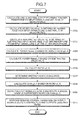
- FIG. 7 is a flowchart illustrating the processing procedure of the signal processing apparatus according to the third embodiment. For example, the process illustrated in FIG. 7 is performed when input signals are received from the microphones 10a and 10b.
- the signal processing apparatus 300 calculates the LIN(i, f) and the RIN(i, f) by performing a Fourier transform on the input signals Lin(t) and Rin(t) of the microphones (step S301).
- the signal processing apparatus 300 calculates the added value p(i, f) obtained by adding together the input signals LIN(i, f) and RIN(i, f) of the microphones (step S302).
- the signal processing apparatus 300 calculates the subtracted value m(i, f) obtained by subtracting the input signal RIN(i, f) of one microphone from the input signal LIN(i, f) of the other microphone (step S303). The signal processing apparatus 300 calculates the power Ppow(i, f) based on the added value p(i, f) (step S304).
- the signal processing apparatus 300 calculates the power Mpow(i, f) based on the subtracted value m(i, f) (step S305).
- the signal processing apparatus 300 calculates the ratio v(i, f) (step S306) and determines whether noise is included (step S307).
- the signal processing apparatus 300 calculates the gain g(i, f) based on the ratio v(i, f) (step S308).
- the signal processing apparatus 300 outputs the output signals LOUT(i, f) and ROUT(i, f) whose noise is suppressed based on the gain g(i, f) (step S309).
- the signal processing apparatus 300 performs an inverse Fourier transform on the output signals LOUT(i, f) and ROUT(i, f) and outputs Lout(t) and Rout(t) (step S310).
- the signal processing apparatus 300 performs a Fourier transform on the input signals Lin(t) and Rin(t) and determines whether there is noise at each frequency. Then, the signal processing apparatus 300 calculates the gain g(i, f) at each frequency and multiplies the input signals LIN(i, f) and RIN(i, f) at each frequency by the gain g(i, f). Therefore, noise at each frequency can be suppressed.
- the processes of the aforementioned signal processing apparatuses 100 to 300 are an example.
- another process of the signal processing apparatuses of the present invention will be described as a fourth embodiment.
- the process according to the fourth embodiment will be described with reference to the configuration diagram in FIG. 1 .
- the gain calculator 160 calculates the gain g(t) by using the formula (7) and the formula (8), it is not limited to this.
- the gain calculator 160 may calculate the gain g(t) by using a decision table indicating a relationship between the gain g(t) and the ratio v(t) for each distance between the microphones 10a and 10b.
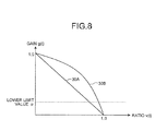
- FIG. 8 is a diagram for explaining the other process of the gain calculator.
- the gain calculator 160 defines that when the distance between the microphones 10a and 10b is 4.2 cm, the relationship between the gain g(t) and the ratio v(t) is a relationship changing as illustrated by a straight line 30A in FIG. 8 .
- the relationship illustrated by the straight line 30A corresponds to the relationship of the formula (7).
- the gain calculator 160 defines that when the distance between the microphones 10a and 10b is smaller than 4.2 cm, the relationship changes as illustrated by a curved line 30B in FIG. 8 .
- the gain calculator 160 sets the change rate of the gain g(t) larger than that indicated by the straight line 30A when the value of the ratio v(t) is about 1 to 0.8.
- the gain calculator 160 performs the process as described above, so that it is possible to accurately suppress noise corresponding to the change of characteristics of the input signals caused by the difference of the distance between the microphones.
- the gain calculator 160 may acquire information of the distance between the microphones 10a and 10b in any manner. A user may input the distance into the signal processing apparatus 100 by using an input device.
- the signal processing apparatus 100 may suppress noise by using microphones 10c and 10d not illustrated in the drawings in addition to the pair of microphones 10a and 10b.
- the signal processing apparatus 100 calculates the ratio v(t) from the microphones 10a and 10b by the same process as that in the first embodiment.
- the v(t) calculated from the microphones 10a and 10b is defined as v1(t).
- the ratio v(t) is calculated from the microphones 10c and 10d by the same process as that in the first embodiment.
- the v(t) calculated from the microphones 10c and 10d is defined as v2(t).
- the signal processing apparatus 100 may adjust the input signals Lin(t) and Rin(t) by the gain g(t).
- the signal processing apparatus 100 may obtain g'(t) by the formula (25) or the formula (26).
- the processes after calculating the g'(t) is the same as that in the first embodiment.
- the g'(t) may be obtained by subtracting the average value of the v1(1) and v2(2) from 1.
- g ⁇ t 1 - v ⁇ 1 t
- g ⁇ t 1 - v ⁇ 2 t
- the gain g(t) is calculated by using the microphones 10a to 10d, so that it is possible to accurately suppress noise of the input signals even when there are a plurality of users.
- the processing units included in the signal processing apparatuses 100 to 300 described in the first to the fourth embodiments correspond to integrated devices such as, for example, ASIC (Application Specific Integrated Circuit) and FPGA (Field Programmable Gate Array). Also, the processing units correspond to electronic circuits such as CPU and MPU (Micro Processing Unit).
- FIG. 9 is a diagram illustrating an example of the computer that executes the signal processing program.
- a computer 400 includes a CPU 401 that performs various calculation processes, an input device 402 that receives input of data from a user, and a display 403.
- the computer 400 also includes a reading device 404 that reads a program and the like from a storage medium and an interface device 405 that transmits and receives data to and from another computer through a network.
- the computer 400 also includes microphones 406a and 406b.
- the computer 400 also includes a RAM 407 that temporarily stores various information and a hard disk device 408.
- the devices 401 to 408 are connected to a bus 409.
- the hard disk device 408 includes, for example, an addition program 408a, a subtraction program 408b, a power calculation program 408c, a ratio calculation program 408d, a determination program 408e, a gain calculation program 408f, and a noise suppression program 408g.
- the CPU 401 reads the programs 408a to 408g and develops the programs in the RAM 407.
- the addition program 408a functions as an addition process 407a.
- the subtraction program 408b functions as a subtraction process 407b.
- the power calculation program 408c functions as a power calculation process 407c.
- the ratio calculation program 408d functions as a ratio calculation process 407d.
- the determination program 408e functions as a determination process 407e.
- the gain calculation program 408f functions as a gain calculation process 407f.
- the noise suppression program 408g functions as a noise suppression process 407g.
- the addition process 407a corresponds to the adder 110.
- the subtraction process 407b corresponds to the subtracter 120.
- the power calculation process 407c corresponds to the power calculators 130a and 130b.
- the ratio calculation process 407d corresponds to the ratio calculator 140.
- the determination process 407e corresponds to the determination unit 150.
- the gain calculation process 407f corresponds to the gain calculator 160.
- the noise suppression process 407g corresponds to the noise suppression unit 170.
- the programs 408a to 408g need not necessarily be stored in the hard disk device 408 from the beginning.
- the programs are stored in a "portable physical medium" such as a flexible disk (FD), a CD-ROM, a DVD disk, a magneto-optical disk, and an IC card which are inserted in the computer 400.
- the computer 400 may read the programs 408a to 408g from these media and execute the programs.
- the programs of the signal processing apparatuses 200 and 300 described in the second to the fourth embodiments are executed by the computer 400 in the same manner as the programs of the signal processing apparatus 100.
Abstract
Description
- The embodiments discussed herein are directed to a signal processing apparatus and the like.
- When wind hits a microphone, a diaphragm included in the microphone vibrates largely, so that noise is included in an input signal. Here, if noise is included in the input signal, when speech recognition is performed or a hands-free phone call is made, the accuracy of the speech recognition and the quality of the phone call degrade. Therefore, in conventional speech recognition and a hands-free phone call, a conventional apparatus which suppresses irregular noise generated when wind hits the microphone is used.
-
FIG. 10 is a diagram illustrating an example of the conventional apparatus. As illustrated inFIG. 10 , aconventional apparatus 10 is connected tomicrophones microphones conventional apparatus 10 includes acorrelation analyzer 11, anoise analyzer 12, and anoise reduction unit 13. - The
microphone 10a is a microphone which converts collected sound into an input signal Lin(t) and outputs the input signal Lin(t) to theconventional apparatus 10. Themicrophone 10b is a microphone which converts collected sound into an input signal Rin(t) and outputs the input signal Rin(t) to theconventional apparatus 10. Here, t corresponds to a sampling number of the input signal. - The
correlation analyzer 11 calculates a correlation value r(t) between the input signal Lin(t) and the input signal Rin(t) by using the formula (1). In the formula (1), thecorrelation analyzer 11 sequentially changes the value of i from 1 to n and calculates a correlation value r(t). For example, the value of n is 128. Thecorrelation analyzer 11 outputs the correlation value r(t) to thenoise analyzer 12.
- When the value of the correlation value r(t) is small, the
noise analyzer 12 determines that there is noise of wind and outputs control information to turn down volume to thenoise reduction unit 13. - The
noise reduction unit 13 adjusts the volumes of the input signals Lin(t) and Rin(t) and outputs the input signals Lin(t) and Rin(t) to an external apparatus. For example, when thenoise reduction unit 13 receives the control information to turn down volume, thenoise reduction unit 13 turns down the volumes of the input signals Lin(t) and Rin(t) and outputs the input signals Lin(t) and Rin(t) to the external apparatus. - Patent Document 1: Japanese Laid-open Patent Publication No.
2004-289762 - Patent Document 2: Japanese Laid-open Patent Publication No.
2009-005133 - However, in the conventional technique described above, there is a problem that noise included in a target input signal such as voice is not sufficiently suppressed.
- For example, in the conventional technique, when wind blowing against the microphone is strong, the noise of the input signal can be suppressed. However, when wind blowing against the microphone is weak, the difference of correlation coefficient between a section including voice and a section including wind hitting noise is small, so that the noise is not accurately suppressed.
- Accordingly, it is an object in one aspect of an embodiment of the invention to provide a signal processing apparatus and a signal processing method that can sufficiently suppress the noise included in the input signal.
- According to an aspect of an embodiment, a signal processing apparatus includes: an adder that acquires a plurality of input signals from a plurality of microphones and calculates an added value obtained by adding the input signals together; a subtracter that acquires a plurality of input signals from the plurality of microphones and calculates a subtracted value obtained by subtracting one input signal from the other input signal; and a determination unit that determines whether noise is included in the input signals based on the added value and the subtracted value.
-
-
FIG. 1 is a diagram illustrating a configuration of a signal processing apparatus according to a first embodiment; -
FIG. 2 is a flowchart illustrating a processing procedure of the signal processing apparatus according to the first embodiment; -
FIG. 3 is a diagram for explaining an effect of the present invention compared with a conventional apparatus; -
FIG. 4 is a diagram illustrating a configuration of a signal processing apparatus according to a second embodiment; -
FIG. 5 is a flowchart illustrating a processing procedure of the signal processing apparatus according to the second embodiment; -
FIG. 6 is a diagram illustrating a configuration of a signal processing apparatus according to a third embodiment; -
FIG. 7 is a flowchart illustrating a processing procedure of the signal processing apparatus according to the third embodiment; -
FIG. 8 is a diagram for explaining another process of a gain calculator; -
FIG. 9 is a diagram illustrating an example of a computer that executes a signal processing program; and -
FIG. 10 is a diagram illustrating an example of a conventional apparatus. - Preferred embodiments of the present invention will be explained with reference to accompanying drawings. The present invention is not limited by the embodiments.
-
FIG. 1 is a diagram illustrating a configuration of a signal processing apparatus according to a first embodiment. As illustrated inFIG. 1 , asignal processing apparatus 100 is connected tomicrophones microphones - The
signal processing apparatus 100 includes anadder 110, asubtracter 120, andpower calculators signal processing apparatus 100 also includes aratio calculator 140, adetermination unit 150, again calculator 160, and anoise suppression unit 170. - The
microphone 10a is a microphone which converts collected sound into an input signal Lin(t) and outputs the input signal Lin(t) to thesignal processing apparatus 100. Themicrophone 10b is a microphone which converts collected sound into an input signal Rin(t) and outputs the input signal Rin(t) to thesignal processing apparatus 100. Here, t corresponds to a sampling number of the input signal. - The
adder 110 calculates an added value p(t) by adding the input signal Lin(t) and the input signal Rin(t) together. The added value p(t) is represented by the formula (2). Theadder 110 outputs the added value p(t) to thepower calculator 130a.
- The
subtracter 120 calculates an subtracted value m(t) by subtracting the input signal Rin(t) from the input signal Lin(t). The subtracted value m(t) is represented by the formula (3). The subtracter 120 outputs the subtracted value m(t) to thepower calculator 130b.
- The
power calculator 130a calculates a power Ppow(t) by summing up squared values of the added value p(t) of different sampling numbers. The power Ppow(t) is represented by the formula (4). Thepower calculator 130a sequentially changes the value of j from 1 to n and calculates the power Ppow(t). The value of n is a natural number. For example, the value of n is 128. Thepower calculator 130a outputs the power Ppow(t) to theratio calculator 140.
- The
power calculator 130b calculates a power Mpow(t) by summing up squared values of the subtracted value m(t) of different sampling numbers. The power Mpow(t) is represented by the formula (5). Thepower calculator 130b sequentially changes the value of j from 1 to n and calculates the power Mpow(t). The value of n is a natural number. For example, the value of n is 128. Thepower calculator 130b outputs the power Mpow(t) to theratio calculator 140.
- The
ratio calculator 140 calculates a ratio v(t) of the power Ppow(t) and the power Mpow(t). For example, theratio calculator 140 calculates the ratio v(t) by the formula (6). Theratio calculator 140 outputs the ratio v(t) to thedetermination unit 150 and thegain calculator 160. Here, v(t) may be a square root of the ratio of the power Ppow(t) and the power Mpow(t).
- The
determination unit 150 determines whether noise is included in the input signals Lin(t) and Rin(t) based on the ratio v(t). When the value of the ratio v(t) is greater than or equal to a predetermined threshold value, thedetermination unit 150 determines that noise is included in the input signals Lin(t) and Rin(t). Thedetermination unit 150 outputs a determination result to thegain calculator 160. - The
gain calculator 160 calculates a gain based on the ratio v(t). Thegain calculator 160 first calculates g'(t) by the formula (7) and thereafter calculates a gain g(t) by the formula (8).

- In the formula (8), α is a lower limit value greater than or equal to 0 and smaller than or equal to 1. The
gain calculator 160 calculates g'(t) and thereafter calculates the larger value of g'(t) and α as the gain g(t). Thegain calculator 160 outputs the gain g(t) to thenoise suppression unit 170. - The
gain calculator 160 may calculate the gain g(t) when noise is included in the input signals Lin(t) and Rin(t) based on the determination result of thedetermination unit 150. On the other hand, when noise is not included in the input signals Lin(t) and Rin(t), thegain calculator 160 may set 1 to the gain g(t) and output the gain g(t) to thenoise suppression unit 170. - The
noise suppression unit 170 suppresses noise by multiplying the input signals Lin(t) and Rin(t) by the gain g(t). For example, thenoise suppression unit 170 generates output signals Lout(t) and Rout(t) from the input signals Lin(t) and Rin(t) and outputs the generated signals to an external apparatus. For example, the output signals Lout(t) and Rout(t) are represented by the formula (9) and the formula (10).

- Next, a processing procedure of the
signal processing apparatus 100 according to the first embodiment will be described.FIG. 2 is a flowchart illustrating a processing procedure of the signal processing apparatus according to the first embodiment. For example, the process illustrated inFIG. 2 is performed when input signals are received from themicrophones - As illustrated in
FIG. 2 , thesignal processing apparatus 100 calculates the added value p(t) obtained by adding together the input signals Lin(t) and Rin(t) of themicrophones signal processing apparatus 100 calculates the subtracted value m(t) obtained by subtracting the input signal Rin(t) of onemicrophone 10b from the input signal Lin(t) of theother microphone 10a (step S102). - The
signal processing apparatus 100 calculates the power Ppow(t) based on the added value p(t) (step S103). Thesignal processing apparatus 100 calculates the power Mpow(t) based on the subtracted value m(t) (step S104). - The
signal processing apparatus 100 calculates the ratio v(t) (step S105) and determines whether noise is included (step S106). Thesignal processing apparatus 100 calculates the gain g(t) based on the ratio v(t) (step S107). Thesignal processing apparatus 100 outputs the output signals Lout(t) and Rout(t) whose noise is suppressed based on the gain g(t) (step S108). - Next, effects of the
signal processing apparatus 100 according to the first embodiment will be described. In thesignal processing apparatus 100, thedetermination unit 150 determines whether noise is included in the input signals Lin(t) and Rin(t) based on the added value p(t) calculated by theadder 110 and the subtracted value m(t) calculated by thesubtracter 120. Therefore, it is possible to accurately determine whether noise is included, so that noise included in the input signals can be sufficiently suppressed by using the determination result. - Generally, the lower the frequency, the stronger the correlation between the input signals. This is because the lower the frequency, the smaller the variation of waveforms in the time axis direction, so that the waveforms have similar shapes. An extreme example is a direct current. Therefore, in order to strengthen the correlation, the
adder 110 sums up the input signals. On the other hand, in order to suppress the correlation, thesubtracter 120 subtracts one input signal from the other input signal. - Therefore, for example, in a case where the input signals of the microphone have a correlation, such as cases of voice and noise in a driving car, a relationship of the formula (11) is established.

- On the other hand, in a case where the correlation between the input signals of the microphone is weak, such as case of wind hitting noise, a relationship of the formula (12) is established.

- Therefore, in the
signal processing apparatus 100 according to the first embodiment, noise can be accurately detected by using the ratio of the "power of (Lin(t)-Rin(t))" based on the "power of (Lin(t)+Rin(t))". Also, an appropriate gain can be calculated by using the ratio of the "power of (Lin(t)-Rin(t))" based on the "power of (Lin(t)+Rin(t))", and a noise component included in the input signals can be suppressed by using the gain. -
FIG. 3 is a diagram for explaining an effect of the present invention compared with a conventional apparatus.Signals 20A inFIG. 3 indicates a relationship between the sampling number and the gain g(t) of the conventional apparatus. Signals 208 inFIG. 3 indicates a relationship between the sampling number and the gain g(t) of thesignal processing apparatus 100.Sections 21 in thesignals signals signals 20B, the gain g(t) in sections including only wind hitting noise is reduced while the gain g(t) in thesections 21 is substantially maintained at 1. Therefore, in the present invention, it is possible to turn down volume of a part of input signals including noise without turning down volume of whole input signals in voice sections. - By the way, in the
signal processing apparatus 100 according to the first embodiment, thedetermination unit 150 determines whether noise is included based on the value of the ratio v(t). However, it is not limited to this. Thedetermination unit 150 may obtain a difference between the Ppow(t) and the Mpow(t), and when the difference value is smaller than a predetermined threshold value, thedetermination unit 150 may determine that noise is included in the input signals. - The
signal processing apparatus 100 may be configured by integrating thedetermination unit 150 and thegain calculator 160 together. - Next, a signal processing apparatus according to a second embodiment will be described.
FIG. 4 is a diagram illustrating a configuration of the signal processing apparatus according to the second embodiment. As illustrated inFIG. 4 , asignal processing apparatus 200 is connected to themicrophones microphones microphones - The
signal processing apparatus 200 includes adelay detector 201 anddelay devices signal processing apparatus 200 also includes anadder 210, asubtracter 220, andpower calculators signal processing apparatus 200 also includes aratio calculator 240, adetermination unit 250, again calculator 260, and anoise suppression unit 270. - The
delay detector 201 calculates a correlation coefficient c(d) between the input signal Lin(t) and the input signal Rin(t) by the formula (13). Thedelay detector 201 changes a delay amount d and detects a delay amount dmax by which the value of correlation coefficient c(d) is the maximum.
- After detecting the dmax, the
delay detector 201 calculates a delay amount dL applied to the input signal from themicrophone 10a and a delay amount dR applied to the input signal from themicrophone 10b in order to synchronize the input signals inputted from themicrophones - When the value of the dmax is greater than or equal to 0, the
delay detector 201 sets the value of dL to 0 and sets the value of dR to the value of the dmax. Then, thedelay detector 201 outputs the dL to thedelay device 202a and outputs the dR to thedelay device 202b. - On the other hand, when the value of the dmax is smaller than 0, the
delay detector 201 sets the value of dL to the absolute value of the dmax and sets the value of dR to 0. Then, thedelay detector 201 outputs the dL to thedelay device 202a and outputs the dR to thedelay device 202b. - The
delay device 202a performs a delay process of the input signal Lin(t) from themicrophone 10a. Thedelay device 202a outputs an input signal Lin(t-dL) obtained by performing a delay process on the input signal Lin(t) to theadder 210 and thesubtracter 220. - The
delay device 202b performs a delay process of the input signal Rin(t) from themicrophone 10b. Thedelay device 202b outputs an input signal Rin(t-dR) obtained by performing a delay process on the input signal Rin(t) to theadder 210 and thesubtracter 220. - The
adder 210 calculates an added value p(t) by adding together the input signals Lin(t-dL) and Rin(t-dR) whose delay amounts are adjusted. Theadder 210 outputs the added value p(t) to thepower calculator 230a. - The
subtracter 220 calculates an subtracted value m(t) by subtracting the input signal Rin(t-dR) from the input signal Lin(t-dL). Thesubtracter 220 outputs the subtracted value m(t) to thepower calculator 230b. - The descriptions about the
power calculators ratio calculator 240, thedetermination unit 250, thegain calculator 260, and thenoise suppression unit 270 are the same as those of thepower calculators ratio calculator 140, thedetermination unit 150, thegain calculator 160, and thenoise suppression unit 170 illustrated inFIG. 1 . - Next, a processing procedure of the
signal processing apparatus 200 according to the second embodiment will be described.FIG. 5 is a flowchart illustrating the processing procedure of the signal processing apparatus according to the second embodiment. For example, the process illustrated inFIG. 5 is performed when input signals are received from themicrophones - The
signal processing apparatus 200 detects the maximum value of the correlation coefficient c(d) between the input signal Lin(t) and the input signal Rin(t) and calculates the delay amounts dL and dR for synchronization (step S201). Thesignal processing apparatus 200 calculates the p(t) by performing synchronous addition (step S202) and calculates the m(t) by performing synchronous subtraction (step S203). - The
signal processing apparatus 200 calculates the power Ppow(t) based on the added value p(t) (step S204). Thesignal processing apparatus 200 calculates the power Mpow(t) based on the subtracted value m(t) (step S205). - The
signal processing apparatus 200 calculates the ratio v(t) (step S206) and determines whether noise is included (step S207). Thesignal processing apparatus 200 calculates the gain g(t) based on the ratio v(t) (step S208). Thesignal processing apparatus 200 outputs the output signals Lout(t) and Rout(t) whose noise is suppressed based on the gain g(t) (step S209). - Next, effects of the
signal processing apparatus 200 according to the second embodiment will be described. In thesignal processing apparatus 200, thedelay detector 201 calculates the delay amounts dL and dR and thedelay devices signal processing apparatus 200, thedetermination unit 250 determines whether noise is included in the input signals Lin(t) and Rin(t) based on the added value p(t) calculated by theadder 210 and the subtracted value m(t) calculated by thesubtracter 220. Therefore, even if the timings when voice of a user is collected by themicrophones - Next, a signal processing apparatus according to the third embodiment will be described.
FIG. 6 is a diagram illustrating a configuration of the signal processing apparatus according to the third embodiment. As illustrated inFIG. 6 , asignal processing apparatus 300 is connected to themicrophones microphones microphones - The
signal processing apparatus 300 includes FFTs (Fast Fourier Transforms) 301a and 301b, anadder 310, asubtracter 320, andpower calculators signal processing apparatus 300 also includes aratio calculator 340, adetermination unit 350, again calculator 360, anoise suppression unit 370, and IFFTs (Inverse FFTs) 371a and 371b. - The
FFT 301a positions a Hanning window with 50% overlap on the input signal Lin(t) acquired from themicrophone 10a and converts the input signal Lin(t) into a signal on the frequency axis by fast Fourier transform. The input signal Lin(t) converted into a signal on the frequency axis is represented as LIN(i, f). Here, i is a number of an analysis frame on which FFT is performed and f indicates the frequency. TheFFT 301a outputs the LIN(i, f) to theadder 310, thesubtracter 320, and thenoise suppression unit 370. - The
FFT 301b positions a Hanning window with 50% overlap on the input signal Rin(t) acquired from themicrophone 10b and converts the input signal Rin(t) into a signal on the frequency axis by fast Fourier transform. The input signal Rin(t) converted into a signal on the frequency axis is represented as RIN(i, f). TheFFT 301b outputs the RIN(i, f) to theadder 310, thesubtracter 320, and thenoise suppression unit 370. TheFFTs - The
adder 310 is a processing unit which calculates an added value p(i, f) by adding the input signal LIN(i, f) and the input signal RIN(i, f) together. The added value p(i, f) is represented by the formula (14). Theadder 310 outputs the added value p(i, f) to thepower calculator 330a.
- The
subtracter 320 calculates a subtracted value m(i, f) by subtracting the input signal RIN(i, f) from the input signal LIN(i, f). The subtracted value m(i, f) is represented by the formula (15). Thesubtracter 320 outputs the subtracted value m(i, f) to thepower calculator 330b.
- The
power calculator 330a calculates a power Ppow(i, f) by summing up squared values of the added value p(i, f) of different frame numbers. The power Ppow(i, f) is represented by the formula (16). Thepower calculator 330a sequentially changes the value of j from 1 to n and calculates the power Ppow(i, f). The value of n is a natural number. For example, the value of n is 128. Thepower calculator 330a outputs the power Ppow(i, f) to theratio calculator 340.
- The
power calculator 330b calculates a power Mpow(i, f) by summing up squared values of the subtracted value m(i, f) of different frame numbers. The power Mpow(i, f) is represented by the formula (17). Thepower calculator 330b sequentially changes the value of j from 1 to n and calculates the power Mpow(i, f). The value of n is a natural number. For example, the value of n is 128. Thepower calculator 330b outputs the power Mpow(i, f) to theratio calculator 340.
- The
ratio calculator 340 calculates a ratio v(i, f) of the power Ppow(i, f) and the power Mpow(i, f). For example, theratio calculator 340 calculates the ratio v(i, f) by the formula (18). Theratio calculator 340 outputs the ratio v(i, f) to thedetermination unit 350 and thegain calculator 360.
- The
determination unit 350 determines whether noise is included in the input signals LIN(i, f) and RIN(i, f) based on the ratio v(i, f). When the value of the ratio v(i, f) is greater than or equal to a predetermined threshold value, thedetermination unit 350 determines that noise is included in the input signals LIN(i, f) and RIN(i, f). Thedetermination unit 350 outputs a determination result to thegain calculator 360. - The
gain calculator 360 calculates a gain based on the ratio v(i, f). Thegain calculator 360 first calculates g'(i, f) by the formula (19) and thereafter calculates a gain g(i, f) by the formula (20).

- In the formula (20), α is a lower limit value greater than or equal to 0 and smaller than or equal to 1. The
gain calculator 360 calculates g'(i, f) and thereafter calculates the larger value of g'(i, f) and α as the gain g(i, f). Thegain calculator 360 outputs the gain g(i, f) to thenoise suppression unit 370. - The
gain calculator 360 may calculate the gain g(i, f) when noise is included in the input signals LIN(i, f) and RIN(i, f) based on the determination result of thedetermination unit 350. On the other hand, when noise is not included in the input signals LIN(i, f) and RIN(i, f), thegain calculator 360 may set 1 to the gain g(i, f) and output the gain g(i, f) to thenoise suppression unit 370. - The
noise suppression unit 370 suppresses noise by multiplying the input signals LIN(i, f) and RIN(i, f) by the gain g(i, f). For example, thenoise suppression unit 370 generates output signals LOUT(i, f) and ROUT(i, f) from the input signals LIN(i, f) and RIN(i, f) and outputs the generated signals to theIFFTs 

- The
IFFT 371a is a processing unit which generates a signal Lin(t) on the time axis by performing an inverse Fourier transform and 50% overlap addition on the LOUT(i, f). TheIFFT 371a outputs the output signal Lin(t) to an external apparatus. - The
IFFT 371b is a processing unit which generates a signal Rin(t) on the time axis by performing an inverse Fourier transform and 50% overlap addition on the ROUT(i, f). TheIFFT 371b outputs the output signal Rin(t) to an external apparatus. - Next, a processing procedure of the
signal processing apparatus 300 according to the third embodiment will be described.FIG. 7 is a flowchart illustrating the processing procedure of the signal processing apparatus according to the third embodiment. For example, the process illustrated inFIG. 7 is performed when input signals are received from themicrophones - As illustrated in
FIG. 7 , thesignal processing apparatus 300 calculates the LIN(i, f) and the RIN(i, f) by performing a Fourier transform on the input signals Lin(t) and Rin(t) of the microphones (step S301). Thesignal processing apparatus 300 calculates the added value p(i, f) obtained by adding together the input signals LIN(i, f) and RIN(i, f) of the microphones (step S302). - The
signal processing apparatus 300 calculates the subtracted value m(i, f) obtained by subtracting the input signal RIN(i, f) of one microphone from the input signal LIN(i, f) of the other microphone (step S303). Thesignal processing apparatus 300 calculates the power Ppow(i, f) based on the added value p(i, f) (step S304). - The
signal processing apparatus 300 calculates the power Mpow(i, f) based on the subtracted value m(i, f) (step S305). Thesignal processing apparatus 300 calculates the ratio v(i, f) (step S306) and determines whether noise is included (step S307). - The
signal processing apparatus 300 calculates the gain g(i, f) based on the ratio v(i, f) (step S308). Thesignal processing apparatus 300 outputs the output signals LOUT(i, f) and ROUT(i, f) whose noise is suppressed based on the gain g(i, f) (step S309). Thesignal processing apparatus 300 performs an inverse Fourier transform on the output signals LOUT(i, f) and ROUT(i, f) and outputs Lout(t) and Rout(t) (step S310). - Next, effects of the
signal processing apparatus 300 according to the third embodiment will be described. Thesignal processing apparatus 300 performs a Fourier transform on the input signals Lin(t) and Rin(t) and determines whether there is noise at each frequency. Then, thesignal processing apparatus 300 calculates the gain g(i, f) at each frequency and multiplies the input signals LIN(i, f) and RIN(i, f) at each frequency by the gain g(i, f). Therefore, noise at each frequency can be suppressed. - The processes of the aforementioned
signal processing apparatuses 100 to 300 are an example. Hereinafter, another process of the signal processing apparatuses of the present invention will be described as a fourth embodiment. The process according to the fourth embodiment will be described with reference to the configuration diagram inFIG. 1 . - Another process of the
gain calculator 160 will be described. Although thegain calculator 160 calculates the gain g(t) by using the formula (7) and the formula (8), it is not limited to this. Thegain calculator 160 may calculate the gain g(t) by using a decision table indicating a relationship between the gain g(t) and the ratio v(t) for each distance between themicrophones -
FIG. 8 is a diagram for explaining the other process of the gain calculator. For example, thegain calculator 160 defines that when the distance between themicrophones straight line 30A inFIG. 8 . The relationship illustrated by thestraight line 30A corresponds to the relationship of the formula (7). - On the other hand, the
gain calculator 160 defines that when the distance between themicrophones curved line 30B inFIG. 8 . In other words, thegain calculator 160 sets the change rate of the gain g(t) larger than that indicated by thestraight line 30A when the value of the ratio v(t) is about 1 to 0.8. Thegain calculator 160 performs the process as described above, so that it is possible to accurately suppress noise corresponding to the change of characteristics of the input signals caused by the difference of the distance between the microphones. - The
gain calculator 160 may acquire information of the distance between themicrophones signal processing apparatus 100 by using an input device. - Another process of the
power calculator 130a will be described. Thepower calculator 130a obtains the power Ppow(t) based on the formula (4). However, instead of the power Ppow(t), an average Pamp(t) of the absolute values may be calculated. For example, thepower calculator 130a obtains the average of the absolute values by the formula (23).
- Similarly, the
power calculator 130b may calculate an average Mamp(t) of the absolute values instead of the power Mpow(t). For example, thepower calculator 130b obtains the average of the absolute values by the formula (24).
- It is known that when the average of the absolute values is obtained, the processing load of the computer is smaller than when the power is obtained. Therefore, when it is configured so that the
power calculators signal processing apparatus 100 can be reduced. - By the way, the
signal processing apparatus 100 may suppress noise by using microphones 10c and 10d not illustrated in the drawings in addition to the pair ofmicrophones signal processing apparatus 100 calculates the ratio v(t) from themicrophones microphones - Also, the ratio v(t) is calculated from the microphones 10c and 10d by the same process as that in the first embodiment. The v(t) calculated from the microphones 10c and 10d is defined as v2(t). When both the v1(t) and v2(t) are greater than a predetermined threshold value, the
signal processing apparatus 100 may adjust the input signals Lin(t) and Rin(t) by the gain g(t). - For example, the
signal processing apparatus 100 may obtain g'(t) by the formula (25) or the formula (26). The processes after calculating the g'(t) is the same as that in the first embodiment. The g'(t) may be obtained by subtracting the average value of the v1(1) and v2(2) from 1.

- In this way, the gain g(t) is calculated by using the
microphones 10a to 10d, so that it is possible to accurately suppress noise of the input signals even when there are a plurality of users. - The processing units included in the
signal processing apparatuses 100 to 300 described in the first to the fourth embodiments correspond to integrated devices such as, for example, ASIC (Application Specific Integrated Circuit) and FPGA (Field Programmable Gate Array). Also, the processing units correspond to electronic circuits such as CPU and MPU (Micro Processing Unit). - Next, an example of a computer that executes a signal processing program which realizes the same function as that of the
signal processing apparatuses 100 to 300 described in the embodiments will be described.FIG. 9 is a diagram illustrating an example of the computer that executes the signal processing program. - As illustrated in
FIG. 9 , acomputer 400 includes aCPU 401 that performs various calculation processes, aninput device 402 that receives input of data from a user, and adisplay 403. Thecomputer 400 also includes areading device 404 that reads a program and the like from a storage medium and aninterface device 405 that transmits and receives data to and from another computer through a network. Thecomputer 400 also includesmicrophones computer 400 also includes aRAM 407 that temporarily stores various information and ahard disk device 408. Thedevices 401 to 408 are connected to abus 409. - The
hard disk device 408 includes, for example, anaddition program 408a, asubtraction program 408b, apower calculation program 408c, aratio calculation program 408d, adetermination program 408e, again calculation program 408f, and anoise suppression program 408g. TheCPU 401 reads theprograms 408a to 408g and develops the programs in theRAM 407. - The
addition program 408a functions as anaddition process 407a. Thesubtraction program 408b functions as asubtraction process 407b. Thepower calculation program 408c functions as apower calculation process 407c. Theratio calculation program 408d functions as aratio calculation process 407d. Thedetermination program 408e functions as adetermination process 407e. Thegain calculation program 408f functions as again calculation process 407f. Thenoise suppression program 408g functions as anoise suppression process 407g. - For example, the
addition process 407a corresponds to theadder 110. Thesubtraction process 407b corresponds to thesubtracter 120. Thepower calculation process 407c corresponds to thepower calculators ratio calculation process 407d corresponds to theratio calculator 140. Thedetermination process 407e corresponds to thedetermination unit 150. Thegain calculation process 407f corresponds to thegain calculator 160. Thenoise suppression process 407g corresponds to thenoise suppression unit 170. - The
programs 408a to 408g need not necessarily be stored in thehard disk device 408 from the beginning. For example, the programs are stored in a "portable physical medium" such as a flexible disk (FD), a CD-ROM, a DVD disk, a magneto-optical disk, and an IC card which are inserted in thecomputer 400. Thecomputer 400 may read theprograms 408a to 408g from these media and execute the programs. The programs of thesignal processing apparatuses computer 400 in the same manner as the programs of thesignal processing apparatus 100. - According to the disclosed signal processing apparatus, there is an effect that noise included in the input signal can be suppressed.
Claims (12)
- A signal processing apparatus (100, 200, 300) comprising:an adder (110, 210, 310) that acquires a plurality of input signals from a plurality of microphones (10a, 10b) and calculates an added value obtained by adding the input signals together;a subtracter (120, 220, 320) that acquires a plurality of input signals from the plurality of microphones (10a, 10b) and calculates a subtracted value obtained by subtracting one input signal from the other input signal; anda determination unit (150, 250, 350) that determines whether noise is included in the input signals based on the added value and the subtracted value.
- The signal processing apparatus (100, 200, 300) according to claim 1, further comprising:a gain calculator (160, 260, 360) that calculates a gain based on the added value and the subtracted value; anda noise suppression unit (170, 270, 370) that suppresses noise of the input signals based on the gain calculated by the gain calculator (160, 260, 360).
- The signal processing apparatus (100, 200, 300) according to claim 1 or 2, wherein the determination unit (150, 250, 350) determines that noise is included in the input signals when a difference between the added value and the subtracted value is smaller than a threshold value.
- The signal processing apparatus (100, 200, 300) according to claim 1 or 2, further comprising
a ratio calculator (140, 240, 340) that calculates a ratio of the subtracted value to the added value,
wherein the determination unit (150, 250, 350) determines that noise is included in the input signals when a value of the ratio calculated by the ratio calculator (140, 240, 340) is greater than or equal to a threshold value. - The signal processing apparatus (200) according to any one of claims 1 to 4, further comprising:a delay detector (201) that acquires input signals from the plurality of microphones (10a, 10b), changes a delay amount of each of the input signals, and detects delay amounts by which a correlation coefficient of the input signals is a maximum; anda delay unit (202a, 202b) that delays each of the input signals based on the delay amounts detected by the delay detector (201),wherein the adder (210) calculates the added value based on the input signals delayed by the delay unit (202a, 202b), andthe subtracter (220) calculates the subtracted value based on the input signals delayed by the delay unit (202a, 202b).
- The signal processing apparatus (300) according to claim 1 or 2, further comprising
a frequency converter (301a, 301b) that acquires input signals from the plurality of microphones (10a, 10b) and converts each of the input signals into a signal on a frequency axis,
wherein the adder (310) calculates the added value based on each signal on the frequency axis, and
the subtracter (320) calculates the subtracted value based on each signal on the frequency axis. - The signal processing apparatus (100, 200, 300) according to claim 4, wherein the gain calculator (160, 260, 360) calculates the gain based on a value of the ratio and information indicating a relationship between the gain and the value of the ratio which varies according to a distance between the microphones (10a, 10b).
- The signal processing apparatus (100, 200, 300) according to claim 4, wherein the ratio calculator (140, 240, 340) calculates a ratio of a value obtained by squaring the subtracted value to a value obtained by squaring the added value.
- The signal processing apparatus (100, 200, 300) according to claim 4, wherein the ratio calculator (140, 240, 340) calculates a ratio of an absolute value of the subtracted value to an absolute value of the added value.
- The signal processing apparatus (100, 200, 300) according to claim 2, wherein
the adder (110, 210, 310) calculates a first added value obtained by adding together input signals acquired from a first microphone and a second microphone and a second added value obtained by adding together input signals acquired from a third microphone and a fourth microphone,
the subtracter (120, 220, 320) calculates a first subtracted value obtained by subtracting an input signal acquired from the second microphone from an input signal acquired from the first microphone and a second subtracted value obtained by subtracting an input signal acquired from the fourth microphone from an input signal acquired from the third microphone, and
the gain calculator (160, 260, 360) calculates a gain based on the first added value, the second added value, the first subtracted value, and the second subtracted value. - A signal processing method comprising:acquiring a plurality of input signals from a plurality of microphones and calculating an added value obtained by adding the input signals together;acquiring a plurality of input signals from the plurality of microphones and calculating a subtracted value obtained by subtracting one input signal from the other input signal; anddetermining whether noise is included in the input signals based on the added value and the subtracted value.
- A signal processing program causing a computer to execute a procedure comprising:acquiring a plurality of input signals from a plurality of microphones and calculating an added value obtained by adding the input signals together;acquiring a plurality of input signals from the plurality of microphones and calculating a subtracted value obtained by subtracting one input signal from the other input signal; anddetermining whether noise is included in the input signals based on the added value and the subtracted value.
Applications Claiming Priority (1)
| Application Number | Priority Date | Filing Date | Title |
|---|---|---|---|
| JP2011274742A JP5929154B2 (en) | 2011-12-15 | 2011-12-15 | Signal processing apparatus, signal processing method, and signal processing program |
Publications (3)
| Publication Number | Publication Date |
|---|---|
| EP2608201A2 true EP2608201A2 (en) | 2013-06-26 |
| EP2608201A3 EP2608201A3 (en) | 2013-07-17 |
| EP2608201B1 EP2608201B1 (en) | 2022-06-01 |
Family
ID=47429554
Family Applications (1)
| Application Number | Title | Priority Date | Filing Date |
|---|---|---|---|
| EP12194568.7A Active EP2608201B1 (en) | 2011-12-15 | 2012-11-28 | Signal processing apparatus and signal processing method |
Country Status (3)
| Country | Link |
|---|---|
| US (1) | US9271075B2 (en) |
| EP (1) | EP2608201B1 (en) |
| JP (1) | JP5929154B2 (en) |
Cited By (1)
| Publication number | Priority date | Publication date | Assignee | Title |
|---|---|---|---|---|
| US10224029B2 (en) | 2013-07-09 | 2019-03-05 | Via Technologies, Inc. | Method for using voiceprint identification to operate voice recognition and electronic device thereof |
Families Citing this family (7)
| Publication number | Priority date | Publication date | Assignee | Title |
|---|---|---|---|---|
| US9516418B2 (en) * | 2013-01-29 | 2016-12-06 | 2236008 Ontario Inc. | Sound field spatial stabilizer |
| US9271100B2 (en) | 2013-06-20 | 2016-02-23 | 2236008 Ontario Inc. | Sound field spatial stabilizer with spectral coherence compensation |
| US9099973B2 (en) * | 2013-06-20 | 2015-08-04 | 2236008 Ontario Inc. | Sound field spatial stabilizer with structured noise compensation |
| US9106196B2 (en) * | 2013-06-20 | 2015-08-11 | 2236008 Ontario Inc. | Sound field spatial stabilizer with echo spectral coherence compensation |
| EP3163903B1 (en) * | 2015-10-26 | 2019-06-19 | Nxp B.V. | Accoustic processor for a mobile device |
| JP6967353B2 (en) * | 2017-02-15 | 2021-11-17 | 三菱重工サーマルシステムズ株式会社 | Air conditioner and air conditioning system |
| US11721353B2 (en) * | 2020-12-21 | 2023-08-08 | Qualcomm Incorporated | Spatial audio wind noise detection |
Citations (2)
| Publication number | Priority date | Publication date | Assignee | Title |
|---|---|---|---|---|
| JP2004289762A (en) | 2003-01-29 | 2004-10-14 | Toshiba Corp | Method of processing sound signal, and system and program therefor |
| JP2009005133A (en) | 2007-06-22 | 2009-01-08 | Sanyo Electric Co Ltd | Wind noise reducing apparatus and electronic device with the wind noise reducing apparatus |
Family Cites Families (18)
| Publication number | Priority date | Publication date | Assignee | Title |
|---|---|---|---|---|
| US4334740A (en) | 1978-09-12 | 1982-06-15 | Polaroid Corporation | Receiving system having pre-selected directional response |
| JPH05308696A (en) * | 1992-05-06 | 1993-11-19 | Matsushita Electric Ind Co Ltd | Wind noise sensor |
| JP3588576B2 (en) * | 2000-04-28 | 2004-11-10 | 日本電信電話株式会社 | Sound pickup device and sound pickup method |
| JP3812887B2 (en) * | 2001-12-21 | 2006-08-23 | 富士通株式会社 | Signal processing system and method |
| US8098844B2 (en) * | 2002-02-05 | 2012-01-17 | Mh Acoustics, Llc | Dual-microphone spatial noise suppression |
| WO2007059255A1 (en) * | 2005-11-17 | 2007-05-24 | Mh Acoustics, Llc | Dual-microphone spatial noise suppression |
| US7171008B2 (en) * | 2002-02-05 | 2007-01-30 | Mh Acoustics, Llc | Reducing noise in audio systems |
| US7895036B2 (en) | 2003-02-21 | 2011-02-22 | Qnx Software Systems Co. | System for suppressing wind noise |
| JP2005110127A (en) * | 2003-10-01 | 2005-04-21 | Canon Inc | Wind noise detecting device and video camera with wind noise detecting device |
| JP2006237816A (en) * | 2005-02-23 | 2006-09-07 | Sanyo Electric Co Ltd | Arithmetic unit, sound pickup device and signal processing program |
| EP1994788B1 (en) * | 2006-03-10 | 2014-05-07 | MH Acoustics, LLC | Noise-reducing directional microphone array |
| JP4367484B2 (en) | 2006-12-25 | 2009-11-18 | ソニー株式会社 | Audio signal processing apparatus, audio signal processing method, and imaging apparatus |
| US20080175407A1 (en) * | 2007-01-23 | 2008-07-24 | Fortemedia, Inc. | System and method for calibrating phase and gain mismatches of an array microphone |
| JP5020845B2 (en) * | 2007-03-01 | 2012-09-05 | キヤノン株式会社 | Audio processing device |
| US8068620B2 (en) * | 2007-03-01 | 2011-11-29 | Canon Kabushiki Kaisha | Audio processing apparatus |
| US7979487B2 (en) * | 2007-10-19 | 2011-07-12 | Sennheiser Electronic Gmbh & Co. Kg | Microphone device |
| JP2010028307A (en) * | 2008-07-16 | 2010-02-04 | Sony Corp | Noise reduction device, method, and program |
| JP4941579B2 (en) * | 2010-06-16 | 2012-05-30 | 船井電機株式会社 | Audio signal transmitter / receiver |
-
2011
- 2011-12-15 JP JP2011274742A patent/JP5929154B2/en active Active
-
2012
- 2012-11-26 US US13/685,079 patent/US9271075B2/en not_active Expired - Fee Related
- 2012-11-28 EP EP12194568.7A patent/EP2608201B1/en active Active
Patent Citations (2)
| Publication number | Priority date | Publication date | Assignee | Title |
|---|---|---|---|---|
| JP2004289762A (en) | 2003-01-29 | 2004-10-14 | Toshiba Corp | Method of processing sound signal, and system and program therefor |
| JP2009005133A (en) | 2007-06-22 | 2009-01-08 | Sanyo Electric Co Ltd | Wind noise reducing apparatus and electronic device with the wind noise reducing apparatus |
Cited By (1)
| Publication number | Priority date | Publication date | Assignee | Title |
|---|---|---|---|---|
| US10224029B2 (en) | 2013-07-09 | 2019-03-05 | Via Technologies, Inc. | Method for using voiceprint identification to operate voice recognition and electronic device thereof |
Also Published As
| Publication number | Publication date |
|---|---|
| JP5929154B2 (en) | 2016-06-01 |
| EP2608201B1 (en) | 2022-06-01 |
| EP2608201A3 (en) | 2013-07-17 |
| US9271075B2 (en) | 2016-02-23 |
| US20130156221A1 (en) | 2013-06-20 |
| JP2013125197A (en) | 2013-06-24 |
Similar Documents
| Publication | Publication Date | Title |
|---|---|---|
| EP2608201A2 (en) | Signal processing apparatus and signal processing method | |
| EP1887831B1 (en) | Method, apparatus and program for estimating the direction of a sound source | |
| US8560308B2 (en) | Speech sound enhancement device utilizing ratio of the ambient to background noise | |
| EP1903560B1 (en) | Sound signal correcting method, sound signal correcting apparatus and computer program | |
| KR101610161B1 (en) | System and method for speech recognition | |
| KR101475864B1 (en) | Apparatus and method for eliminating noise | |
| US20130070939A1 (en) | Signal processing apparatus | |
| JP5310494B2 (en) | Signal processing method, information processing apparatus, and signal processing program | |
| US10679641B2 (en) | Noise suppression device and noise suppressing method | |
| US20090232318A1 (en) | Output correcting device and method, and loudspeaker output correcting device and method | |
| US20110238417A1 (en) | Speech detection apparatus | |
| EP2927906B1 (en) | Method and apparatus for detecting voice signal | |
| US9247347B2 (en) | Noise suppression apparatus and control method thereof | |
| EP2920949B1 (en) | Echo suppression | |
| US9754606B2 (en) | Processing apparatus, processing method, program, computer readable information recording medium and processing system | |
| JP5982900B2 (en) | Noise suppression device, microphone array device, noise suppression method, and program | |
| KR101621780B1 (en) | Method fomethod for judgment of drinking using differential frequency energy, recording medium and device for performing the method | |
| US11004463B2 (en) | Speech processing method, apparatus, and non-transitory computer-readable storage medium for storing a computer program for pitch frequency detection based upon a learned value | |
| US10636438B2 (en) | Method, information processing apparatus for processing speech, and non-transitory computer-readable storage medium | |
| KR101488787B1 (en) | Apparatus and method for estimating doppler frequency in mobile communication terminal | |
| KR101569343B1 (en) | Mmethod for judgment of drinking using differential high-frequency energy, recording medium and device for performing the method | |
| Graf et al. | Low-Complexity Pitch Estimation Based on Phase Differences Between Low-Resolution Spectra. | |
| KR20100071898A (en) | Impulsive noise detector, method of detecting impulsive noise and impulsive noise remover system | |
| JP2005080240A (en) | Symbol timing estimation apparatus | |
| JP2020134778A (en) | Noise elimination device, noise elimination method and program |
Legal Events
| Date | Code | Title | Description |
|---|---|---|---|
| PUAL | Search report despatched |
Free format text: ORIGINAL CODE: 0009013 |
|
| AK | Designated contracting states |
Kind code of ref document: A2 Designated state(s): AL AT BE BG CH CY CZ DE DK EE ES FI FR GB GR HR HU IE IS IT LI LT LU LV MC MK MT NL NO PL PT RO RS SE SI SK SM TR |
|
| AX | Request for extension of the european patent |
Extension state: BA ME |
|
| PUAI | Public reference made under article 153(3) epc to a published international application that has entered the european phase |
Free format text: ORIGINAL CODE: 0009012 |
|
| AK | Designated contracting states |
Kind code of ref document: A3 Designated state(s): AL AT BE BG CH CY CZ DE DK EE ES FI FR GB GR HR HU IE IS IT LI LT LU LV MC MK MT NL NO PL PT RO RS SE SI SK SM TR |
|
| AX | Request for extension of the european patent |
Extension state: BA ME |
|
| RIC1 | Information provided on ipc code assigned before grant |
Ipc: G10L 25/84 20130101AFI20130610BHEP Ipc: G10L 21/0216 20130101ALI20130610BHEP |
|
| 17P | Request for examination filed |
Effective date: 20140108 |
|
| RBV | Designated contracting states (corrected) |
Designated state(s): AL AT BE BG CH CY CZ DE DK EE ES FI FR GB GR HR HU IE IS IT LI LT LU LV MC MK MT NL NO PL PT RO RS SE SI SK SM TR |
|
| 17Q | First examination report despatched |
Effective date: 20160720 |
|
| STAA | Information on the status of an ep patent application or granted ep patent |
Free format text: STATUS: EXAMINATION IS IN PROGRESS |
|
| STAA | Information on the status of an ep patent application or granted ep patent |
Free format text: STATUS: EXAMINATION IS IN PROGRESS |
|
| STAA | Information on the status of an ep patent application or granted ep patent |
Free format text: STATUS: EXAMINATION IS IN PROGRESS |
|
| GRAP | Despatch of communication of intention to grant a patent |
Free format text: ORIGINAL CODE: EPIDOSNIGR1 |
|
| STAA | Information on the status of an ep patent application or granted ep patent |
Free format text: STATUS: GRANT OF PATENT IS INTENDED |
|
| RIC1 | Information provided on ipc code assigned before grant |
Ipc: G10L 21/0216 20130101ALN20220218BHEP Ipc: H04R 3/00 20060101ALI20220218BHEP Ipc: G10L 25/84 20130101AFI20220218BHEP |
|
| INTG | Intention to grant announced |
Effective date: 20220307 |
|
| GRAS | Grant fee paid |
Free format text: ORIGINAL CODE: EPIDOSNIGR3 |
|
| GRAA | (expected) grant |
Free format text: ORIGINAL CODE: 0009210 |
|
| STAA | Information on the status of an ep patent application or granted ep patent |
Free format text: STATUS: THE PATENT HAS BEEN GRANTED |
|
| AK | Designated contracting states |
Kind code of ref document: B1 Designated state(s): AL AT BE BG CH CY CZ DE DK EE ES FI FR GB GR HR HU IE IS IT LI LT LU LV MC MK MT NL NO PL PT RO RS SE SI SK SM TR |
|
| REG | Reference to a national code |
Ref country code: GB Ref legal event code: FG4D |
|
| REG | Reference to a national code |
Ref country code: AT Ref legal event code: REF Ref document number: 1495946 Country of ref document: AT Kind code of ref document: T Effective date: 20220615 Ref country code: CH Ref legal event code: EP Ref country code: DE Ref legal event code: R096 Ref document number: 602012078288 Country of ref document: DE |
|
| REG | Reference to a national code |
Ref country code: IE Ref legal event code: FG4D |
|
| REG | Reference to a national code |
Ref country code: FR Ref legal event code: PLFP Year of fee payment: 11 |
|
| REG | Reference to a national code |
Ref country code: LT Ref legal event code: MG9D |
|
| REG | Reference to a national code |
Ref country code: NL Ref legal event code: MP Effective date: 20220601 |
|
| PG25 | Lapsed in a contracting state [announced via postgrant information from national office to epo] |
Ref country code: SE Free format text: LAPSE BECAUSE OF FAILURE TO SUBMIT A TRANSLATION OF THE DESCRIPTION OR TO PAY THE FEE WITHIN THE PRESCRIBED TIME-LIMIT Effective date: 20220601 Ref country code: NO Free format text: LAPSE BECAUSE OF FAILURE TO SUBMIT A TRANSLATION OF THE DESCRIPTION OR TO PAY THE FEE WITHIN THE PRESCRIBED TIME-LIMIT Effective date: 20220901 Ref country code: LT Free format text: LAPSE BECAUSE OF FAILURE TO SUBMIT A TRANSLATION OF THE DESCRIPTION OR TO PAY THE FEE WITHIN THE PRESCRIBED TIME-LIMIT Effective date: 20220601 Ref country code: HR Free format text: LAPSE BECAUSE OF FAILURE TO SUBMIT A TRANSLATION OF THE DESCRIPTION OR TO PAY THE FEE WITHIN THE PRESCRIBED TIME-LIMIT Effective date: 20220601 Ref country code: GR Free format text: LAPSE BECAUSE OF FAILURE TO SUBMIT A TRANSLATION OF THE DESCRIPTION OR TO PAY THE FEE WITHIN THE PRESCRIBED TIME-LIMIT Effective date: 20220902 Ref country code: FI Free format text: LAPSE BECAUSE OF FAILURE TO SUBMIT A TRANSLATION OF THE DESCRIPTION OR TO PAY THE FEE WITHIN THE PRESCRIBED TIME-LIMIT Effective date: 20220601 Ref country code: ES Free format text: LAPSE BECAUSE OF FAILURE TO SUBMIT A TRANSLATION OF THE DESCRIPTION OR TO PAY THE FEE WITHIN THE PRESCRIBED TIME-LIMIT Effective date: 20220601 Ref country code: BG Free format text: LAPSE BECAUSE OF FAILURE TO SUBMIT A TRANSLATION OF THE DESCRIPTION OR TO PAY THE FEE WITHIN THE PRESCRIBED TIME-LIMIT Effective date: 20220901 |
|
| PGFP | Annual fee paid to national office [announced via postgrant information from national office to epo] |
Ref country code: GB Payment date: 20220907 Year of fee payment: 11 |
|
| REG | Reference to a national code |
Ref country code: AT Ref legal event code: MK05 Ref document number: 1495946 Country of ref document: AT Kind code of ref document: T Effective date: 20220601 |
|
| PG25 | Lapsed in a contracting state [announced via postgrant information from national office to epo] |
Ref country code: RS Free format text: LAPSE BECAUSE OF FAILURE TO SUBMIT A TRANSLATION OF THE DESCRIPTION OR TO PAY THE FEE WITHIN THE PRESCRIBED TIME-LIMIT Effective date: 20220601 Ref country code: PL Free format text: LAPSE BECAUSE OF FAILURE TO SUBMIT A TRANSLATION OF THE DESCRIPTION OR TO PAY THE FEE WITHIN THE PRESCRIBED TIME-LIMIT Effective date: 20220601 Ref country code: LV Free format text: LAPSE BECAUSE OF FAILURE TO SUBMIT A TRANSLATION OF THE DESCRIPTION OR TO PAY THE FEE WITHIN THE PRESCRIBED TIME-LIMIT Effective date: 20220601 |
|
| PGFP | Annual fee paid to national office [announced via postgrant information from national office to epo] |
Ref country code: FR Payment date: 20220901 Year of fee payment: 11 |
|
| PG25 | Lapsed in a contracting state [announced via postgrant information from national office to epo] |
Ref country code: NL Free format text: LAPSE BECAUSE OF FAILURE TO SUBMIT A TRANSLATION OF THE DESCRIPTION OR TO PAY THE FEE WITHIN THE PRESCRIBED TIME-LIMIT Effective date: 20220601 |
|
| PG25 | Lapsed in a contracting state [announced via postgrant information from national office to epo] |
Ref country code: SM Free format text: LAPSE BECAUSE OF FAILURE TO SUBMIT A TRANSLATION OF THE DESCRIPTION OR TO PAY THE FEE WITHIN THE PRESCRIBED TIME-LIMIT Effective date: 20220601 Ref country code: SK Free format text: LAPSE BECAUSE OF FAILURE TO SUBMIT A TRANSLATION OF THE DESCRIPTION OR TO PAY THE FEE WITHIN THE PRESCRIBED TIME-LIMIT Effective date: 20220601 Ref country code: RO Free format text: LAPSE BECAUSE OF FAILURE TO SUBMIT A TRANSLATION OF THE DESCRIPTION OR TO PAY THE FEE WITHIN THE PRESCRIBED TIME-LIMIT Effective date: 20220601 Ref country code: PT Free format text: LAPSE BECAUSE OF FAILURE TO SUBMIT A TRANSLATION OF THE DESCRIPTION OR TO PAY THE FEE WITHIN THE PRESCRIBED TIME-LIMIT Effective date: 20221003 Ref country code: EE Free format text: LAPSE BECAUSE OF FAILURE TO SUBMIT A TRANSLATION OF THE DESCRIPTION OR TO PAY THE FEE WITHIN THE PRESCRIBED TIME-LIMIT Effective date: 20220601 Ref country code: CZ Free format text: LAPSE BECAUSE OF FAILURE TO SUBMIT A TRANSLATION OF THE DESCRIPTION OR TO PAY THE FEE WITHIN THE PRESCRIBED TIME-LIMIT Effective date: 20220601 Ref country code: AT Free format text: LAPSE BECAUSE OF FAILURE TO SUBMIT A TRANSLATION OF THE DESCRIPTION OR TO PAY THE FEE WITHIN THE PRESCRIBED TIME-LIMIT Effective date: 20220601 |
|
| PGFP | Annual fee paid to national office [announced via postgrant information from national office to epo] |
Ref country code: DE Payment date: 20220818 Year of fee payment: 11 |
|
| PG25 | Lapsed in a contracting state [announced via postgrant information from national office to epo] |
Ref country code: IS Free format text: LAPSE BECAUSE OF FAILURE TO SUBMIT A TRANSLATION OF THE DESCRIPTION OR TO PAY THE FEE WITHIN THE PRESCRIBED TIME-LIMIT Effective date: 20221001 |
|
| REG | Reference to a national code |
Ref country code: DE Ref legal event code: R097 Ref document number: 602012078288 Country of ref document: DE |
|
| PG25 | Lapsed in a contracting state [announced via postgrant information from national office to epo] |
Ref country code: AL Free format text: LAPSE BECAUSE OF FAILURE TO SUBMIT A TRANSLATION OF THE DESCRIPTION OR TO PAY THE FEE WITHIN THE PRESCRIBED TIME-LIMIT Effective date: 20220601 |
|
| PLBE | No opposition filed within time limit |
Free format text: ORIGINAL CODE: 0009261 |
|
| STAA | Information on the status of an ep patent application or granted ep patent |
Free format text: STATUS: NO OPPOSITION FILED WITHIN TIME LIMIT |
|
| PG25 | Lapsed in a contracting state [announced via postgrant information from national office to epo] |
Ref country code: DK Free format text: LAPSE BECAUSE OF FAILURE TO SUBMIT A TRANSLATION OF THE DESCRIPTION OR TO PAY THE FEE WITHIN THE PRESCRIBED TIME-LIMIT Effective date: 20220601 |
|
| 26N | No opposition filed |
Effective date: 20230302 |
|
| PG25 | Lapsed in a contracting state [announced via postgrant information from national office to epo] |
Ref country code: SI Free format text: LAPSE BECAUSE OF FAILURE TO SUBMIT A TRANSLATION OF THE DESCRIPTION OR TO PAY THE FEE WITHIN THE PRESCRIBED TIME-LIMIT Effective date: 20220601 |
|
| PG25 | Lapsed in a contracting state [announced via postgrant information from national office to epo] |
Ref country code: MC Free format text: LAPSE BECAUSE OF FAILURE TO SUBMIT A TRANSLATION OF THE DESCRIPTION OR TO PAY THE FEE WITHIN THE PRESCRIBED TIME-LIMIT Effective date: 20220601 |
|
| REG | Reference to a national code |
Ref country code: CH Ref legal event code: PL |
|
| REG | Reference to a national code |
Ref country code: BE Ref legal event code: MM Effective date: 20221130 |
|
| PG25 | Lapsed in a contracting state [announced via postgrant information from national office to epo] |
Ref country code: LI Free format text: LAPSE BECAUSE OF NON-PAYMENT OF DUE FEES Effective date: 20221130 Ref country code: CH Free format text: LAPSE BECAUSE OF NON-PAYMENT OF DUE FEES Effective date: 20221130 |
|
| PG25 | Lapsed in a contracting state [announced via postgrant information from national office to epo] |
Ref country code: LU Free format text: LAPSE BECAUSE OF NON-PAYMENT OF DUE FEES Effective date: 20221128 |
|
| PG25 | Lapsed in a contracting state [announced via postgrant information from national office to epo] |
Ref country code: IE Free format text: LAPSE BECAUSE OF NON-PAYMENT OF DUE FEES Effective date: 20221128 |
|
| PG25 | Lapsed in a contracting state [announced via postgrant information from national office to epo] |
Ref country code: BE Free format text: LAPSE BECAUSE OF NON-PAYMENT OF DUE FEES Effective date: 20221130 |
|
| PG25 | Lapsed in a contracting state [announced via postgrant information from national office to epo] |
Ref country code: IT Free format text: LAPSE BECAUSE OF FAILURE TO SUBMIT A TRANSLATION OF THE DESCRIPTION OR TO PAY THE FEE WITHIN THE PRESCRIBED TIME-LIMIT Effective date: 20220601 |
|
| PG25 | Lapsed in a contracting state [announced via postgrant information from national office to epo] |
Ref country code: HU Free format text: LAPSE BECAUSE OF FAILURE TO SUBMIT A TRANSLATION OF THE DESCRIPTION OR TO PAY THE FEE WITHIN THE PRESCRIBED TIME-LIMIT; INVALID AB INITIO Effective date: 20121128 |