EP2661008A1 - Preamble extensions for communications - Google Patents
Preamble extensions for communications Download PDFInfo
- Publication number
- EP2661008A1 EP2661008A1 EP13020068.6A EP13020068A EP2661008A1 EP 2661008 A1 EP2661008 A1 EP 2661008A1 EP 13020068 A EP13020068 A EP 13020068A EP 2661008 A1 EP2661008 A1 EP 2661008A1
- Authority
- EP
- European Patent Office
- Prior art keywords
- sig
- symbol
- symbols
- spatial streams
- vht
- Prior art date
- Legal status (The legal status is an assumption and is not a legal conclusion. Google has not performed a legal analysis and makes no representation as to the accuracy of the status listed.)
- Withdrawn
Links
Images


Classifications
-
- H—ELECTRICITY
- H04—ELECTRIC COMMUNICATION TECHNIQUE
- H04B—TRANSMISSION
- H04B7/00—Radio transmission systems, i.e. using radiation field
- H04B7/02—Diversity systems; Multi-antenna system, i.e. transmission or reception using multiple antennas
- H04B7/04—Diversity systems; Multi-antenna system, i.e. transmission or reception using multiple antennas using two or more spaced independent antennas
- H04B7/0413—MIMO systems
-
- C—CHEMISTRY; METALLURGY
- C08—ORGANIC MACROMOLECULAR COMPOUNDS; THEIR PREPARATION OR CHEMICAL WORKING-UP; COMPOSITIONS BASED THEREON
- C08F—MACROMOLECULAR COMPOUNDS OBTAINED BY REACTIONS ONLY INVOLVING CARBON-TO-CARBON UNSATURATED BONDS
- C08F214/00—Copolymers of compounds having one or more unsaturated aliphatic radicals, each having only one carbon-to-carbon double bond, and at least one being terminated by a halogen
- C08F214/18—Monomers containing fluorine
-
- H—ELECTRICITY
- H04—ELECTRIC COMMUNICATION TECHNIQUE
- H04B—TRANSMISSION
- H04B7/00—Radio transmission systems, i.e. using radiation field
- H04B7/02—Diversity systems; Multi-antenna system, i.e. transmission or reception using multiple antennas
- H04B7/04—Diversity systems; Multi-antenna system, i.e. transmission or reception using multiple antennas using two or more spaced independent antennas
- H04B7/0413—MIMO systems
- H04B7/0452—Multi-user MIMO systems
-
- H—ELECTRICITY
- H04—ELECTRIC COMMUNICATION TECHNIQUE
- H04B—TRANSMISSION
- H04B7/00—Radio transmission systems, i.e. using radiation field
- H04B7/02—Diversity systems; Multi-antenna system, i.e. transmission or reception using multiple antennas
- H04B7/04—Diversity systems; Multi-antenna system, i.e. transmission or reception using multiple antennas using two or more spaced independent antennas
- H04B7/06—Diversity systems; Multi-antenna system, i.e. transmission or reception using multiple antennas using two or more spaced independent antennas at the transmitting station
- H04B7/0613—Diversity systems; Multi-antenna system, i.e. transmission or reception using multiple antennas using two or more spaced independent antennas at the transmitting station using simultaneous transmission
- H04B7/0615—Diversity systems; Multi-antenna system, i.e. transmission or reception using multiple antennas using two or more spaced independent antennas at the transmitting station using simultaneous transmission of weighted versions of same signal
-
- H—ELECTRICITY
- H04—ELECTRIC COMMUNICATION TECHNIQUE
- H04B—TRANSMISSION
- H04B7/00—Radio transmission systems, i.e. using radiation field
- H04B7/02—Diversity systems; Multi-antenna system, i.e. transmission or reception using multiple antennas
- H04B7/04—Diversity systems; Multi-antenna system, i.e. transmission or reception using multiple antennas using two or more spaced independent antennas
- H04B7/06—Diversity systems; Multi-antenna system, i.e. transmission or reception using multiple antennas using two or more spaced independent antennas at the transmitting station
- H04B7/0613—Diversity systems; Multi-antenna system, i.e. transmission or reception using multiple antennas using two or more spaced independent antennas at the transmitting station using simultaneous transmission
- H04B7/0667—Diversity systems; Multi-antenna system, i.e. transmission or reception using multiple antennas using two or more spaced independent antennas at the transmitting station using simultaneous transmission of delayed versions of same signal
- H04B7/0671—Diversity systems; Multi-antenna system, i.e. transmission or reception using multiple antennas using two or more spaced independent antennas at the transmitting station using simultaneous transmission of delayed versions of same signal using different delays between antennas
-
- H—ELECTRICITY
- H04—ELECTRIC COMMUNICATION TECHNIQUE
- H04B—TRANSMISSION
- H04B7/00—Radio transmission systems, i.e. using radiation field
- H04B7/02—Diversity systems; Multi-antenna system, i.e. transmission or reception using multiple antennas
- H04B7/04—Diversity systems; Multi-antenna system, i.e. transmission or reception using multiple antennas using two or more spaced independent antennas
- H04B7/06—Diversity systems; Multi-antenna system, i.e. transmission or reception using multiple antennas using two or more spaced independent antennas at the transmitting station
- H04B7/0613—Diversity systems; Multi-antenna system, i.e. transmission or reception using multiple antennas using two or more spaced independent antennas at the transmitting station using simultaneous transmission
- H04B7/068—Diversity systems; Multi-antenna system, i.e. transmission or reception using multiple antennas using two or more spaced independent antennas at the transmitting station using simultaneous transmission using space frequency diversity
-
- H—ELECTRICITY
- H04—ELECTRIC COMMUNICATION TECHNIQUE
- H04B—TRANSMISSION
- H04B7/00—Radio transmission systems, i.e. using radiation field
- H04B7/02—Diversity systems; Multi-antenna system, i.e. transmission or reception using multiple antennas
- H04B7/04—Diversity systems; Multi-antenna system, i.e. transmission or reception using multiple antennas using two or more spaced independent antennas
- H04B7/06—Diversity systems; Multi-antenna system, i.e. transmission or reception using multiple antennas using two or more spaced independent antennas at the transmitting station
- H04B7/0613—Diversity systems; Multi-antenna system, i.e. transmission or reception using multiple antennas using two or more spaced independent antennas at the transmitting station using simultaneous transmission
- H04B7/0684—Diversity systems; Multi-antenna system, i.e. transmission or reception using multiple antennas using two or more spaced independent antennas at the transmitting station using simultaneous transmission using different training sequences per antenna
-
- H—ELECTRICITY
- H04—ELECTRIC COMMUNICATION TECHNIQUE
- H04L—TRANSMISSION OF DIGITAL INFORMATION, e.g. TELEGRAPHIC COMMUNICATION
- H04L27/00—Modulated-carrier systems
- H04L27/18—Phase-modulated carrier systems, i.e. using phase-shift keying
- H04L27/22—Demodulator circuits; Receiver circuits
-
- H—ELECTRICITY
- H04—ELECTRIC COMMUNICATION TECHNIQUE
- H04L—TRANSMISSION OF DIGITAL INFORMATION, e.g. TELEGRAPHIC COMMUNICATION
- H04L5/00—Arrangements affording multiple use of the transmission path
- H04L5/0001—Arrangements for dividing the transmission path
- H04L5/0014—Three-dimensional division
- H04L5/0023—Time-frequency-space
-
- H—ELECTRICITY
- H04—ELECTRIC COMMUNICATION TECHNIQUE
- H04L—TRANSMISSION OF DIGITAL INFORMATION, e.g. TELEGRAPHIC COMMUNICATION
- H04L5/00—Arrangements affording multiple use of the transmission path
- H04L5/003—Arrangements for allocating sub-channels of the transmission path
- H04L5/0048—Allocation of pilot signals, i.e. of signals known to the receiver
- H04L5/0051—Allocation of pilot signals, i.e. of signals known to the receiver of dedicated pilots, i.e. pilots destined for a single user or terminal
-
- H—ELECTRICITY
- H04—ELECTRIC COMMUNICATION TECHNIQUE
- H04W—WIRELESS COMMUNICATION NETWORKS
- H04W88/00—Devices specially adapted for wireless communication networks, e.g. terminals, base stations or access point devices
- H04W88/02—Terminal devices
-
- H—ELECTRICITY
- H04—ELECTRIC COMMUNICATION TECHNIQUE
- H04W—WIRELESS COMMUNICATION NETWORKS
- H04W88/00—Devices specially adapted for wireless communication networks, e.g. terminals, base stations or access point devices
- H04W88/08—Access point devices
Definitions
- the following description relates generally to communication systems, and more particularly to Preamble Extensions.
- MIMO Multiple Input, Multiple Output
- IEEE 802.11 denotes a set of Wireless Local Area Network (WLAN) air interface standards developed by the IEEE 802.11 committee for short-range communications (e.g., tens of meters to a few hundred meters).
- WLAN Wireless Local Area Network
- the new 802.11 VHT (Very High Throughput) is a new standard, which operates in MIMO mode. MIMO technology may be used by a transmitter to communicate with several receivers using Spatial-Division Multiple Access (SDMA). SDMA is a multiple access scheme which enables multiple streams transmitted to different receivers at the same time to share the same frequency spectrum. Within any given stream, there are data packets that contain both data and preamble. Designing efficient preambles are needed to handle the new technology.
- SDMA Spatial-Division Multiple Access
- an apparatus for communications comprises a processing system configured to generate a plurality of spatial streams.
- Each of the spatial streams comprises a plurality of symbols.
- the processing system is further configured to distribute at least a portion of a training sequence across a first symbol in a first one of the spatial streams and a second symbol in a second one of the spatial streams.
- a method for communications comprises generating a plurality of spatial streams wherein each of the spatial streams comprises a plurality of symbols. The method further comprises distributing at least a portion of a training sequence across a first symbol in a first one of the spatial streams and a second symbol in a second one of the spatial streams.
- an apparatus for communications comprises means for generating a plurality of spatial streams, wherein each of the spatial streams comprises a plurality of symbols.
- the apparatus further comprises means for distributing at least a portion of a training sequence across a first symbol in a first one of the spatial streams and a second symbol in a second one of the spatial streams.
- a computer-program product for wireless communication comprises a machine-readable medium encoded with instructions executable to generate a plurality of spatial streams, wherein each of the spatial streams comprises a plurality of symbols.
- the machine-readable medium is further encoded with instructions executable to distribute at least a portion of a training sequence across a first symbol in a first one of the spatial streams and a second symbol in a second one of the spatial streams.
- an access point comprises a processing system configured to generate a plurality of spatial streams, wherein each of the spatial streams comprises a plurality of symbols.
- the processing system is further configured to distribute at least a portion of a training sequence across a first symbol in a first one of the spatial streams and a second symbol in a second one of the spatial streams.
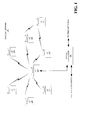
- FIG. 1 is a diagram of a wireless communications network
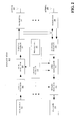
- FIG. 2 is a block diagram illustrating an example of a wireless node
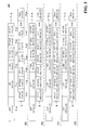
- FIG. 3 is a diagram depicting an exemplary Mixed-Mode preamble with 3 rd HT-SIG symbol
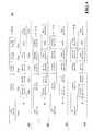
- FIG. 4 is a diagram depicting an exemplary Greenfield preamble with 3 rd HT-SIG symbol
- FIG. 5 is a diagram depicting an exemplary preamble with an extra HT-LTF
- FIG. 6 is a diagram depicting an exemplary VHT-only-Greenfield preamble
- FIG. 7 is a diagram depicting an exemplary alternative Mixed-Mode preamble with extra HT-STF
- FIG. 8 is a diagram depicting exemplary shortened channel training for four spatial streams
- FIG. 9 is a diagram depicting exemplary channel training for eight spatial streams.
- FIG. 10 is a diagram depicting exemplary alternative channel training for eight spatial streams
- FIG. 11 is a diagram depicting an exemplary VHT-only-Greenfield preamble with extended HT-LTF
- FIG. 12 is a diagram depicting exemplary channel training for sixteen spatial streams
- FIG. 13 is a diagram depicting an exemplary VHT Greenfield preamble with different STF and LTF;
- FIG. 14 is a diagram depicting an exemplary VHT Greenfield frame format
- FIG. 15 is a diagram depicting an exemplary VHT Greenfield frame format for open loop MIMO
- FIG. 16 is a diagram depicting an exemplary VHT Mixed-Mode frame format
- FIG. 17 is a diagram depicting an exemplary VHT Mixed-Mode frame format for open loop MIMO
- FIG. 18 is a diagram depicting an exemplary uplink frame format
- FIG. 19 is a diagram depicting an exemplary alternative VHT Greenfield frame format
- FIG. 20 is a diagram depicting an exemplary alternative VHT Greenfield frame format for open loop MIMO
- FIG. 21 is a diagram depicting an exemplary alternative VHT Mixed-Mode frame format
- FIG. 22 is a diagram depicting an exemplary alternative VHT Mixed-Mode frame format for open loop MIMO.
- FIG. 23 is a diagram depicting an exemplary alternative uplink frame format.
- the wireless network 100 is shown with several wireless nodes, generally designated as nodes 110 and 120. Each wireless node is capable of receiving and/or transmitting.
- the term “access point” is used to designate a transmitting node and the term “access terminal” is used to designate a receiving node for downlink communications
- the term “access point” is used to designate a receiving node
- the term “access terminal” is used to designate a transmitting node for uplink communications.
- other terminology or nomenclature may be used for an access point and/or access terminal.
- an access point may be referred to as a base station, a base transceiver station, a station, a terminal, a node, an access terminal acting as an access point, or some other suitable terminology.
- An access terminal may be referred to as a user terminal, a mobile station, a subscriber station, a station, a wireless device, a terminal, a node, or some other suitable terminology.
- the wireless network 100 may support any number of access points distributed throughout a geographic region to provide coverage for access terminals 120.
- a system controller 130 may be used to provide coordination and control of the access points, as well as access to other networks (e.g., Internet) for the access terminals 120.
- one access point 110 is shown.
- An access point is generally a fixed terminal that provides backhaul services to access terminals in the geographic region of coverage, however, the access point may be mobile in some applications.
- An access terminal which may be fixed or mobile, utilizes the backhaul services of an access point or engages in peer-to-peer communications with other access terminals.
- access terminals include a telephone (e.g., cellular telephone), a laptop computer, a desktop computer, a Personal Digital Assistant (PDA), a digital audio player (e.g., MP3 player), a camera, a game console, or any other suitable wireless node.
- a telephone e.g., cellular telephone
- laptop computer e.g., a laptop computer
- desktop computer e.g., a desktop computer
- PDA Personal Digital Assistant
- digital audio player e.g., MP3 player
- camera e.g., a game console, or any other suitable wireless node.
- the wireless network 100 may support MIMO technology.
- an access point 110 may communicate with multiple access terminals 120 simultaneously using SDMA.
- SDMA is a multiple access scheme which enables multiple streams transmitted to different receivers at the same time to share the same frequency channel and, as a result, provide higher user capacity. This is achieved by spatially precoding each data stream and then transmitting each spatially precoded stream through a different transmit antenna on the downlink.
- the spatially precoded data streams arrive at the access terminals with different spatial signatures, which enables each access terminal 120 to recover the data stream destined for that access terminal 120.
- One or more access terminals 120 may be equipped with multiple antennas to enable certain functionality. With this configuration, multiple antennas at the access point 110 may be used to communicate with a multiple antenna access point to improve data throughput without additional bandwidth or transmit power. This may be achieved by splitting a high data rate signal at the transmitter into multiple lower rate data streams with different spatial signatures, thus enabling the receiver to separate these streams into multiple channels and properly combine the streams to recover the high rate data signal.
- the access point 110 may also be configured to support access terminals that do not support MIMO technology. This approach may allow older versions of access terminals (i.e., "legacy" terminals) to remain deployed in a wireless network, extending their useful lifetime, while allowing newer MIMO access terminals to be introduced as appropriate.
- legacy terminals older versions of access terminals
- OFDM Orthogonal Frequency Division Multiplexing
- An OFDM system may implement IEEE 802.11, or some other air interface standard.
- CDMA Code Division Multiple Access
- TDMA Time Division Multiple Access
- a CDMA system may implement with IS-2000, IS-95, IS-856, Wideband-CDMA (WCDMA), or some other suitable air interface standard.
- WCDMA Wideband-CDMA
- a TDMA system may implement Global System for Mobile Communications (GSM) or some other suitable air interface standard.
- GSM Global System for Mobile Communications
- FIG. 2 is a conceptual block diagram illustrating an example of a wireless node.
- a TX data processor 202 may be used to receive data from a data source 201 and encode (e.g., Turbo code) the data to facilitate forward error correction (FEC) at the receiving node.
- FEC forward error correction
- the encoding process results in a sequence of code symbols that may be blocked together and mapped to a signal constellation by the TX data processor 202 to produce a sequence of modulation symbols.
- the modulation symbols from the TX data processor 202 may be provided to an OFDM modulator 204.
- the OFDM modulator 204 splits the modulation symbols into a number of parallel streams and then maps each stream to a subcarrier using some modulation constellation.
- An Inverse Fast Fourier Transform (IFFT) is then performed on each set of subcarriers to produce time domain OFDM symbols, with each OFDM symbol having a set of subcarriers.
- IFFT Inverse Fast Fourier Transform
- a preamble is carried along with the payload in each data packet.
- the preamble may be comprised of several symbols which are provided to the OFDM modulator 204 by a preamble unit 203.
- the OFDM modulator 204 splits the preamble symbols into a number of parallel streams, and then maps each stream to a subcarrier using some modulation constellation.
- An (IFFT) is then performed on each set of subcarriers to produce one or more time domain OFDM symbols which constitutes the preamble.
- the preamble is then appended to payload carried by each data packet before providing the data packets to a TX spatial processor 205.
- a TX spatial processor 205 performs spatial processing on the data packets. This may be accomplished by spatially precoding the data packets into a number of spatially precoded streams and then providing each spatially precoded stream to a different antenna 208 via a transceiver 206. Each transceiver 206 modulates an RF carrier with a respective precoded stream for transmission over the wireless channel.
- each transceiver 206 receives a signal through its respective antenna 208.
- Each transceiver 206 may be used to recover the information modulated onto an RF carrier and provide the information to a RX spatial processor 210.
- the RX spatial processor 210 performs spatial processing on the information to recover data packets carried any spatial streams destined for the wireless node 200.
- the spatial processing may be performed in accordance with Channel Correlation Matrix Inversion (CCMI), Minimum Mean Square Error (MMSE), Soft Interference Cancellation (SIC), or some other suitable technique.
- CCMI Channel Correlation Matrix Inversion
- MMSE Minimum Mean Square Error
- SIC Soft Interference Cancellation
- the preamble unit 203 will use the preamble in each data packet to provide synchronization information to the OFDM demodulator 212.
- the OFDM demodulator 212 recovers the data carried on each subcarrier in the OFDM symbols in the payload of the data packet and multiplexes the data into a stream of modulation symbols.
- the OFDM demodulator 212 converts the stream from time-domain to the frequency domain using a Fast Fourier Transfer (FFT).
- FFT Fast Fourier Transfer
- the channel estimator 215 receives the streams from the OFDM demodulator 212 and estimates the channel response. As part of the preamble there may be a set of pilot signals. Each pilot signal will be generally shifted in phase due to the transmission through the wireless channel. The MMSE estimates of the phase shifted pilot signals are computed and the MMSE estimates are used to estimate phase errors and consequently the channel response. The channel response is provided to the RX data processor 214.
- the RX data processor 214 is used to translate the modulation symbols back to the correct point in the signal constellation. Because of noise and other disturbances in the wireless channel, the modulation symbols may not correspond to an exact location of a point in the original signal constellation. Using the channel response, the RX data processor 214 detects which modulation symbol was most likely transmitted by finding the smallest distance between the received point and the location of a valid symbol in the signal constellation. These soft decisions may be used, in the case of Turbo codes, for example, to compute a Log-Likelihood Ratio (LLR) of the code symbols associated with the given modulation symbols. The RX data processor 214 then uses the sequence of code symbol LLRs and the phase error estimates in order to decode the data that was originally transmitted before providing the data to a data sink 218.
- LLR Log-Likelihood Ratio
- a preamble within each data packet includes a training sequence.
- a training sequence contains a number of modulated symbols.
- a training sequence may comprise a Short Training Field (STF) and/or a Long Training Field (LTF).
- the preamble unit 203 together with the OFDM modulator 204 creates preambles according to the following mechanisms.
- the preambles are generated by distributing at least one symbol containing information indicating a length of data and a modulation scheme. Such information may be different for at least two of the data packets.
- the preamble unit 203 is further configured to distribute at least a portion of a training sequence or the STF or LTF, across a first symbol in a first one of the data packets and across a second symbol in a second one of the data packets.
- the preamble unit 203 is used to aid the OFDM demodulator 212 in decoding the data packets. The following is description of additional details about the operational steps taken by the preamble unit 203 on the transmit side.
- the preambles may also be generated by a distribution of a further portion of the training sequence into a third symbol in a third one of the data packets, or into another symbol in the first one of the data packets that temporally follows the first symbol, or into another symbol on a third one of the data packets that temporally follows the first symbol.
- the portion of the training sequence in the first symbol may be distributed into a fourth symbol in the first one of the spatial streams that temporally follows the third symbol.
- the training sequences are distributed across different subcarriers in the first and second symbols.
- the portion of the training sequence in the first symbol may be cyclically delayed.
- the signal carried by the subcarriers may be multiplied by the portion of the training sequence in the first symbol.
- the first symbol includes multiple in-band and out-of-band subcarriers, then the portion of the training sequence in the first symbol is distributed across the in-band subcarriers, and the out-of-bound subcarriers are attenuated.
- At least one of the symbols may be modulated with a spoof modulation scheme. Furthermore, one of the symbols in the first one of the spatial streams may be modulated with a first modulation scheme, and another one of the symbols in the first one of the spatial streams may be modulated with a second modulation scheme that is different from the first modulation scheme.
- the following figures illustrate a number of exemplary preambles that may be constructed.
- the new exemplary preambles start with existing 11n (802.11 version n) preambles and include High Throughput-Signals (HT-SIG) using spoofed rate and length field.
- Extra HT-SIG fields are used for signaling new modes and modified High Throughput-Long Training Fields (HT-LTF) are used for channel estimation of more tones and/or more spatial streams.
- HT-LTF High Throughput-Long Training Fields
- a 3rd HT-SIG symbol is inserted after existing HT-SIG symbols.
- a Binary Phase Shift Keying (BPSK) spoof rate is used with one spatial stream in 11n HT-SIG.
- BPSK Binary Phase Shift Keying
- Existing rotated-BPSK mechanism is used to detect the presence of the 3rd HT-SIG.
- a HT-LTF may use more subcarriers than 11n in a 40 MHz 11n subchannel. To avoid legacy problems, the first HT-LTF uses 11n subcarriers. This would lead to having 114 subcarriers in each 40 MHz subchannel.
- a 3rd HT-SIG is inserted after first HT-LTF.
- the 3rd HT-SIG may not be inserted after existing HT-SIG because a gain step is performed at that point.
- a BPSK spoof rate is used with 1 spatial stream in 11n HT-SIG, and existing rotated-BPSK mechanism is used to detect the presence of the 3rd HT-SIG.
- one extra symbol using rotated BPSK may be employed if 24 extra signaling bits are enough. Two extra symbols using rotated BPSK can result in more overhead.
- One extra symbol using Quadrature Phase Shift Keying (QPSK) may result in Signal Noise Ratio (SNR) penalty in detecting QPSK versus rotated BPSK.
- the pilots of the extra HT-SIG3 can be inverted.
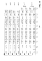
- FIG. 3 is a diagram depicting a set of example Mixed-Mode preambles 300 with a 3rd HT-SIG symbol, which includes Mixed-Mode preambles 302-308.
- the 3rd HT-SIG has a different sign and cyclic delay than HT-SIG1 and HT-SIG2 to match the sign and cyclic delay of HT-LTF.
- All symbols up to the High Throughput-Short Training Field (HT-STF) are 11n 40 MHz copies in two 40 MHz channels, possibly with a 90 degrees phase rotation. Symbols after HT-STF may use tone filling to have more subcarriers than two 11n 40 MHz channels.
- the set of example Mixed-Mode preambles 300 shown in FIG. 3 is for four antennas, this can be extended to eight by using different cyclic delays on the other four antennas.
- FIG. 4 is a diagram depicting a set of example Greenfield preambles 400 with 3rd HT-SIG symbol, which includes Greenfield preambles 402-408.
- Legacy 11n devices have to defer based on HT-SIG1&2 that contains a spoof length and spoof BPSK rate.
- BPSK check is rotated on HT-SIG3 to detect the new mode.
- FIG. 5 is a diagram depicting a set of example preambles 500 with an extra HT-LTF, which includes preambles 502-508.
- the preambles contained in the set of preambles 500 of FIG. 5 are similar to the set of example Greenfield preambles 400, but with an extra HT-LTF. As such, there is no need to do tone filling in the first HT-LTF.
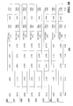
- FIG. 6 is a diagram depicting a set of example VHT-only-Greenfield preambles 600, which includes VHT-only-Greenfield preambles 602-608.
- the set of example VHT-only-Greenfield preambles 600 shown in FIG. 6 is used for VHT networks or within a transmit operation when the medium is reserved for some time. Detection of this preamble is done by a QPSK detect on HT-SIG3 or by using inverted pilots in HT-SIG3.
- This preamble is for 4 spatial streams, it can be extended to 8 or more by using different cyclic delays and by using different HT-LTFs.
- FIG. 7 is a diagram depicting a set of example alternative Mixed-Mode preambles 700 with extra HT-STF, which includes alternative Mixed-Mode preambles 702-708.
- the set of example alternative Mixed-Mode preambles 700 shown in FIG. 7 may be used in combination with beamforming, where beamforming can start after HT-SIG3 such that there are no hidden node problems up to HT-SIG3. There may be an additional 8 microseconds in the preamble - one extra HT-STF and one extra HT-LTF. This alternative preamble may not be necessary if all devices are required to defer for the length indicated by HT-SIG1&2.
- more HT-LTF symbols may be used.
- HT-LTF symbols e.g., 8 symbols with a length 8 Walsh codes for 8 spatial streams.
- CDD cyclic delay
- CDD cyclic delay diversity
- FIG. 8 is a diagram depicting a set of example shortened channel training sequences 800 for four spatial streams, which includes shortened channel training sequences 802-808.
- a 1600 ns CDD in combination with a Walsh code for separating 2 pairs of spatial streams, may be used.
- Channel truncation and interpolation may be needed in the receiver to do channel training.
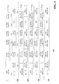
- FIG. 9 is a diagram depicting a set of example channel training sequences 900 for eight spatial streams, which includes shortened channel training sequences 902-916. Similar to the example shown for Fig. 8 , a 1600 ns CDD in combination with a Walsh code for separating 2 pairs of spatial streams may also be used in this case. Channel truncation and interpolation may also be needed in a receiver to perform channel training.
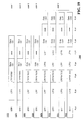
- FIG. 10 is a diagram depicting a set of example alternative channel training sequences 1000 for eight spatial streams, which includes shortened channel training sequences 1002-1016.
- impulse responses for each spatial stream may have to be limited to 800 ns in order to separate 4 spatial streams after the adding and subtracting of both columns.
- guard time of the channel training symbols may be increased.
- the 11n system uses a guard time of 800 ns which is required to deal with delay spread. By increasing this guard time to 1600 ns or even more, a significant amount of samples in every HT-LTF can be used to estimate a frequency error per symbol.
- a 2800 ns guard interval would give a HT-LTF symbol duration of 6 microseconds with 2 microseconds available for frequency estimation.
- the frequency estimation can be done by comparing the phase of the samples in the interval 800 ns to 2800 ns to the samples in the interval 4000 ns to 6000 ns.
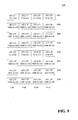
- FIG. 11 is a diagram depicting a set of example VHT-only-Greenfield preambles 1100 with extended HT-LTF, which includes VHT-only-Greenfield preambles 1102-1116. More specifically, FIG. 11 shows a 38 microseconds preamble for 8 spatial streams in a 80 MHz channel (11n Greenfield preamble is 36 microseconds for 4 spatial streams). The HT-LTF could be extended to 8 microseconds, making the preamble 44 microseconds.
- Existing Nss -spatial stream channel training HN such as the described 8-spatial stream training, can be used to make a new training pattern to double the number of spatial streams by the following equation.
- H 2 ⁇ N H N H N H N - H N
- a 16-spatial stream preamble can be made that is as long as the 8-spatial stream preambles but with the double number of HT-LTF symbols.
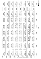
- FIG. 12 is a diagram depicting a set of example channel training sequence 1200 for sixteen spatial streams, which includes channel training sequences 1202-1232.
- a single spatial stream followed by a SDMA downlink beamforming matrix may be used. For example, for a 2-space-time-stream client, one may first generate two VHT-SIG copies with a CDD of -400 ns. Then a beamforming matrix can be applied to obtain, for instance, 8 TX (transmit) signals (in case of an AP with 8 antennas).
- VHT-SIG for uplink
- clients may transmit a preamble with a number of spatial streams being equal to the max number of spatial streams that AP can handle.
- the number of spatial streams may be greater than the total number of all uplink streams.
- AP can do MIMO detection on different VHT-SIGs after the HT-LTF channel estimation.
- the preambles described above can be used, however each user would need to transmit on a different part of the available spatial streams. For instance, if there are 3 users and 16 spatial streams, user 1 transmits using spatial streams 1-8, user two transmits using streams 9-14, and user 3 transmits using streams 15-16.
- VHT-SIG There may be an issue with the VHT-SIG that may need to be different per user unless the AP already knows in advance what modulation and packet length each user has).
- One possibility would be to have a VHT-SIG after last VHT-LTF.
- VHT-SIG in SDMA uplink it is assumed that AP knows in advance how many streams each client transmits. This can be fulfilled, for example, by some scheduled mechanism. After the last VHT-LTF, each client may transmit a VHT-SIG copy with a different CDD on each spatial stream.
- STF short training fields
- AGC Automotive Gain Control
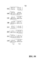
- FIG. 13 is a diagram depicting a set of example VHT Greenfield preambles 1300 with different STF and LTF, which includes VHT Greenfield preambles 1302-1316.
- each preamble in the set of VHT Greenfield preambles 1300 can be extended to 16 spatial streams by adding 8 different STF<F and by using a 8x8 Walsh-Hadamard encoding on groups of two LTF symbols.
- the scheme shown in FIG. 13 uses a 4x4 Walsh-Hadamard encoding on groups of two LTF symbols.
- the following are the 1600ns cyclic delayed pairs: ⁇ LTF1,LTF2), ⁇ LTF3,LTF4 ⁇ , ⁇ LTF5,LTF6 ⁇ , ⁇ LTF7,LTF8 ⁇ , such that LTF1 LTF2 multiplied by a ⁇ 1,-1,1,-1,... ⁇ pattern in the frequency domain.
- the VHT-SIG subcarriers for Transmitter m are multiplied by their corresponding LTF m subcarrier values. This makes it possible to decode VHT-SIG before receiving all LTF symbols, similar to the decoding of HT-SIG in an 11n packet.
- the data symbols may use a cyclic delay value CD m , e.g., m *200 ns to prevent any undesired beamforming effects.
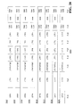
- FIG. 14 is a diagram depicting a set of example VHT Greenfield frame formats 1400, which includes VHT Greenfield frame formats 1402-1416. Referring to FIG. 14 , each user can have 1 to 8 spatial streams, resulting in different preamble lengths per user.
- FIG. 15 is a diagram depicting a set of example VHT Greenfield frame formats 1500 for open loop MIMO.
- the set of example VHT Greenfield frame formats 1500 may be used in VHT-only networks or in a transmit operation preceded by an 802.11n NAV (Net Allocation Vector) setting.
- Preamble length including VHT-SIG is 32 microseconds for 8 spatial streams.
- the format can be extended to 16 spatial streams by adding 4 more LTFs. All parts of the frame are identically precoded in case of SDMA.
- Content of VHT-SIG is identical on spatial streams intended for the same user.
- VHT-SIG subcarriers are multiplied by LTF frequency domain values, which make it possible for each user to perform a Single Input or Multiple Output (SIMO) decoding of VHT-SIG using the first received LTF for channel estimation.
- SIMO Single Input or Multiple Output
- Same frame formats may be used for open-loop MIMO. All VHT-SIG contents are identical in this case as there is only one receiving user.
- a VHT-GF may be detected by QPSK detection on VHT-SIG or by detecting inverted pilots in VHT-SIG.
- FIG. 16 is a diagram depicting a set of example Very High Throughput-Mixed- Mode (VHT -MM) frame formats 1600, which includes VHT-MM frame formats 1602-1616.
- VHT -MM Very High Throughput-Mixed- Mode
- FIG. 17 is a diagram depicting a set of example VHT-MM frame formats 1700 for open loop MIMO, which includes VHT-MM frame formats 1702-1716.
- Preamble length including VHT-SIG is 52 microseconds for 8 spatial streams.
- the format can be extended to 16 spatial streams by adding 4 more LTFs.
- the SDMA beamforming starts after HT-SIG2.
- Contents of VHT-SIG are identical on spatial streams intended for the same user.
- VHT-SIG subcarriers are multiplied by LTF frequency domain values, which makes it possible for each user to do a SIMO decoding of VHT-SIG using the first received LTF for channel estimation.
- the same frame format is used for open-loop MIMO. All VHT-SIG contents are identical in this case as there is only one receiving user.
- VHT-MM can be detected by rotated-BPSK check on VHT-SIG, or by QPSK detection on VHT-SIG (if VHT-SIG QPSK is used to get more bits in one symbol) or by detecting inverted pilots in VHT-SIG.
- One may use BPSK 11n-spoof rate, such that the receiver will distinguish between the BPSK data symbol and the VHT-SIG when detecting VHT-MM.
- HT-SIG content is fully 11n compliant, without having to use reserved bits.
- VHT-SIG cannot be directly after the HT-SIG because of the AGC gain setting that is done immediately after HT-SIG on (V)HT-STF. Cyclic delay values are multiples of -200 ns (the same values as used in LTF when cyclic delayed LTF symbol is used).
- FIG. 18 is a diagram depicting a set of example uplink frame formats 1800, which includes uplink frame formats 1802-1816.
- Each uplink user uses a different subset of the available spatial streams ranging from 1-8 or 1-16.
- There is no mixed-mode preamble as it is assumed that there will always be an AP packet indicating the start of the uplink SDMA transmit operation (TXOP), which can include 11n NAV setting.
- TXOP uplink SDMA transmit operation
- VHT-SIG comes after all LTF symbols because the AP needs to do a MIMO detection on different VHT-SIGs per user. If a user transmits more than one spatial stream, its VHT-SIG content will be the same on all streams it transmits.
- the AP has to know in advance how many spatial stream each user has. So, this information does not need to be in VHT-SIG.
- Uplink frame format may not be used for open-loop MIMO because one may not know in advance how many spatial streams there are. Therefore, a VHT SIG would be desirable to have before all the channel trainings.
- FIG. 19 is a diagram depicting a set of example alternative VHT Greenfield frame formats 1900, which includes alternative VHT Greenfield frame formats 1902-1916. Each user can have 1 to 8 spatial streams, resulting in different preamble lengths per user.
- FIG. 20 is a diagram depicting a set of example alternative VHT Greenfield frame formats 2000 for open loop MIMO, which include alternative VHT Greenfield frame formats 2002-2016.
- the notation "LTF1*VHT-SIG" means an element-wise multiplication per subcarrier.
- Each VHT-SIG subcarrier is multiplied by the corresponding LTF subcarrier value.
- the LTF subcarrier value may include a phase rotation caused by a cyclic delay.
- the LTF symbols are tone interleaved.
- LTF has non-zero elements only at subcarriers.
- the LTF symbols may use one or more out-of-band tones to facilitate simpler and more accurate tone interpolation.
- Out-of-band tones are tones that are not used in data symbols.
- LTF out-of-band tones may be attenuated by a prescribed amount so that they would have less impact on the transmitted spectral mask.
- VHT-LTF subcarrier values are defined as:
- Nsc is the total number of subcarriers
- Nss is the maximum number of spatial streams in the uplink (4 or 2)
- L(k) is the k th subcarrier value of a binary long training symbol pattern, which may be the 802.11n long training symbol for cases that use the same number as subcarriers as 802.11n.
- VHT-LTF0 has non-zero values only at tones ⁇ 0,8,16,...,52 ⁇
- VHT-LTF1 has non-zero tones at ⁇ 1,9,17,...,53 ⁇ .
- FIG. 21 is a diagram depicting a set of example alternative VHT-MM frame formats 2100, which includes alternative VHT-MM frame formats 2102-2118.
- FIG. 22 is a diagram depicting a set of example alternative VHT-MM frame formats 2200 for open loop MIMO, which includes alternative VHT-MM frame formats 2202-2218.
- FIG. 23 is a diagram depicting a set of example alternative uplink frame formats 2300, which includes alternative uplink frame formats 2302-2316.
- Each uplink user uses a different subset of the available spatial streams ranging from 1-8 or 1-16.
- There is no mixed-mode preamble as it is assumed that there will always be an AP packet indicating the start of the uplink SDMA transmit operation.
- VHT-SIG comes after all LTF symbols because the AP needs to do a MIMO detection on the different VHT-SIG per user. If a user transmits more than one spatial stream, its VHT-SIG content is the same on all streams it transmits. AP needs to know in advance how many spatial stream each user has. Uplink frame format may not be used for open-loop MIMO because it is not known in advance how many spatial streams there are, so there is a need to have a VHT SIG before all channel trainings.
- the preamble unit, the OFDM modulator, and the OFDM demodulator may be implemented with one or more general purpose processors, digital signal processors (DSP)s, application specific integrated circuits (ASIC)s, field programmable gate array (FPGA)s, programmable logic devices (PLD)s, other programmable logic components, discrete gate or transistor logic, discrete hardware components, or any combination thereof designed to perform the functions described herein.
- DSP digital signal processor
- ASIC application specific integrated circuits
- FPGA field programmable gate array
- PLD programmable logic devices
- a general purpose processor may be a microprocessor, a controller, a microcontroller, a state machine, or any other circuitry that can execute software.
- Software shall be construed broadly to mean instructions, data, or any combination thereof, whether referred to as software, firmware, middleware, microcode, hardware description language, or otherwise.
- Machine-readable media may include various memory components including, by way of example, Random Access Memory (RAM), flash memory, Read Only Memory (ROM), Programmable Read-Only Memory (PROM), Erasable Programmable Read-Only Memory (EPROM), Electrically Erasable Programmable Read-Only Memory (EEPROM), registers, magnetic disks, optical disks, hard drives, or any other suitable storage medium, or any combination thereof.
- Machine-readable media may also be include a transmission line, a carrier wave modulated by data, and/or other means for providing software to the wireless node.
- the machine-readable may be embodied in a computer-program product.
- the computer-program product may comprise packaging materials.
Abstract
Description
- The present Application for Patent claims priority to Provisional Application No.
61/090,434 - The following description relates generally to communication systems, and more particularly to Preamble Extensions.
- In order to address the issue of increasing bandwidth requirements that are demanded for wireless communications systems, different schemes are being developed to allow multiple user terminals to communicate with a single access point by sharing channel resources while achieving high data throughputs. Multiple Input, Multiple Output (MIMO) technology represents one such approach that has recently emerged as a popular technique for next generation communication systems. MIMO technology has been adopted in several emerging wireless communications standards such as the Institute of Electrical Engineers (IEEE) 802.11 standard. IEEE 802.11 denotes a set of Wireless Local Area Network (WLAN) air interface standards developed by the IEEE 802.11 committee for short-range communications (e.g., tens of meters to a few hundred meters).
- The new 802.11 VHT (Very High Throughput) is a new standard, which operates in MIMO mode. MIMO technology may be used by a transmitter to communicate with several receivers using Spatial-Division Multiple Access (SDMA). SDMA is a multiple access scheme which enables multiple streams transmitted to different receivers at the same time to share the same frequency spectrum. Within any given stream, there are data packets that contain both data and preamble. Designing efficient preambles are needed to handle the new technology.
- In one aspect of the disclosure, an apparatus for communications comprises a processing system configured to generate a plurality of spatial streams. Each of the spatial streams comprises a plurality of symbols. The processing system is further configured to distribute at least a portion of a training sequence across a first symbol in a first one of the spatial streams and a second symbol in a second one of the spatial streams.
- In another aspect of the disclosure, a method for communications comprises generating a plurality of spatial streams wherein each of the spatial streams comprises a plurality of symbols. The method further comprises distributing at least a portion of a training sequence across a first symbol in a first one of the spatial streams and a second symbol in a second one of the spatial streams.
- In yet another aspect of the disclosure, an apparatus for communications comprises means for generating a plurality of spatial streams, wherein each of the spatial streams comprises a plurality of symbols. The apparatus further comprises means for distributing at least a portion of a training sequence across a first symbol in a first one of the spatial streams and a second symbol in a second one of the spatial streams.
- In a further aspect of the disclosure, a computer-program product for wireless communication comprises a machine-readable medium encoded with instructions executable to generate a plurality of spatial streams, wherein each of the spatial streams comprises a plurality of symbols. The machine-readable medium is further encoded with instructions executable to distribute at least a portion of a training sequence across a first symbol in a first one of the spatial streams and a second symbol in a second one of the spatial streams.
- In yet a further aspect of the disclosure, an access point, comprises a processing system configured to generate a plurality of spatial streams, wherein each of the spatial streams comprises a plurality of symbols. The processing system is further configured to distribute at least a portion of a training sequence across a first symbol in a first one of the spatial streams and a second symbol in a second one of the spatial streams.
- These and other sample aspects of the invention will be described in the detailed description that follows, and in the accompanying drawings, wherein:
-
FIG. 1 is a diagram of a wireless communications network; -
FIG. 2 is a block diagram illustrating an example of a wireless node; -
FIG. 3 is a diagram depicting an exemplary Mixed-Mode preamble with 3rd HT-SIG symbol; -
FIG. 4 is a diagram depicting an exemplary Greenfield preamble with 3rd HT-SIG symbol; -
FIG. 5 is a diagram depicting an exemplary preamble with an extra HT-LTF; -
FIG. 6 is a diagram depicting an exemplary VHT-only-Greenfield preamble; -
FIG. 7 is a diagram depicting an exemplary alternative Mixed-Mode preamble with extra HT-STF; -
FIG. 8 is a diagram depicting exemplary shortened channel training for four spatial streams; -
FIG. 9 is a diagram depicting exemplary channel training for eight spatial streams; -
FIG. 10 is a diagram depicting exemplary alternative channel training for eight spatial streams; -
FIG. 11 is a diagram depicting an exemplary VHT-only-Greenfield preamble with extended HT-LTF; -
FIG. 12 is a diagram depicting exemplary channel training for sixteen spatial streams; -
FIG. 13 is a diagram depicting an exemplary VHT Greenfield preamble with different STF and LTF; -
FIG. 14 is a diagram depicting an exemplary VHT Greenfield frame format; -
FIG. 15 is a diagram depicting an exemplary VHT Greenfield frame format for open loop MIMO; -
FIG. 16 is a diagram depicting an exemplary VHT Mixed-Mode frame format; -
FIG. 17 is a diagram depicting an exemplary VHT Mixed-Mode frame format for open loop MIMO; -
FIG. 18 is a diagram depicting an exemplary uplink frame format; -
FIG. 19 is a diagram depicting an exemplary alternative VHT Greenfield frame format; -
FIG. 20 is a diagram depicting an exemplary alternative VHT Greenfield frame format for open loop MIMO; -
FIG. 21 is a diagram depicting an exemplary alternative VHT Mixed-Mode frame format; -
FIG. 22 is a diagram depicting an exemplary alternative VHT Mixed-Mode frame format for open loop MIMO; and -
FIG. 23 is a diagram depicting an exemplary alternative uplink frame format. - In accordance with common practice, some of the drawings may be simplified for clarity. Thus, the drawings may not depict all of the components of a given apparatus (e.g., device) or method. Finally, like reference numerals may be used to denote like features throughout the specification and figures.
- Various aspects of the invention are described more fully hereinafter with reference to the accompanying drawings. This invention may, however, be embodied in many different forms and should not be construed as limited to any specific structure or function presented throughout this disclosure. Rather, these aspects are provided so that this disclosure will be thorough and complete, and will fully convey the scope of the invention to those skilled in the art. Based on the teachings herein, one skilled in the art should appreciate that the scope of the invention is intended to cover any aspect of the invention disclosed herein, whether implemented independently of or combined with any other aspect of the invention. For example, an apparatus may be implemented or a method may be practiced using any number of the aspects set forth herein. In addition, the scope of the invention is intended to cover such an apparatus or method which is practiced using other structure, functionality, or structure and functionality in addition to or other than the various aspects of the invention set forth herein. It should be understood that any aspect of the invention disclosed herein may be embodied by one or more elements of a claim.
- Several aspects of a wireless network will now be presented with reference to
FIG. 1 . Thewireless network 100 is shown with several wireless nodes, generally designated asnodes 110 and 120. Each wireless node is capable of receiving and/or transmitting. In the detailed description that follows, the term "access point" is used to designate a transmitting node and the term "access terminal" is used to designate a receiving node for downlink communications, whereas the term "access point" is used to designate a receiving node and the term "access terminal" is used to designate a transmitting node for uplink communications. However, those skilled in the art will readily understand that other terminology or nomenclature may be used for an access point and/or access terminal. By way of example, an access point may be referred to as a base station, a base transceiver station, a station, a terminal, a node, an access terminal acting as an access point, or some other suitable terminology. An access terminal may be referred to as a user terminal, a mobile station, a subscriber station, a station, a wireless device, a terminal, a node, or some other suitable terminology. The various concepts described throughout this disclosure are intended to apply to all suitable wireless nodes regardless of their specific nomenclature. - The
wireless network 100 may support any number of access points distributed throughout a geographic region to provide coverage foraccess terminals 120. Asystem controller 130 may be used to provide coordination and control of the access points, as well as access to other networks (e.g., Internet) for theaccess terminals 120. For simplicity, one access point 110 is shown. An access point is generally a fixed terminal that provides backhaul services to access terminals in the geographic region of coverage, however, the access point may be mobile in some applications. An access terminal, which may be fixed or mobile, utilizes the backhaul services of an access point or engages in peer-to-peer communications with other access terminals. Examples of access terminals include a telephone (e.g., cellular telephone), a laptop computer, a desktop computer, a Personal Digital Assistant (PDA), a digital audio player (e.g., MP3 player), a camera, a game console, or any other suitable wireless node. - The
wireless network 100 may support MIMO technology. Using MIMO technology, an access point 110 may communicate withmultiple access terminals 120 simultaneously using SDMA. As explained in the background section of this disclosure, SDMA is a multiple access scheme which enables multiple streams transmitted to different receivers at the same time to share the same frequency channel and, as a result, provide higher user capacity. This is achieved by spatially precoding each data stream and then transmitting each spatially precoded stream through a different transmit antenna on the downlink. The spatially precoded data streams arrive at the access terminals with different spatial signatures, which enables eachaccess terminal 120 to recover the data stream destined for thataccess terminal 120. On the uplink, eachaccess terminal 120 transmits a spatially precoded data stream, which enables the access point 110 to identify the source of each spatially precoded data stream. - One or
more access terminals 120 may be equipped with multiple antennas to enable certain functionality. With this configuration, multiple antennas at the access point 110 may be used to communicate with a multiple antenna access point to improve data throughput without additional bandwidth or transmit power. This may be achieved by splitting a high data rate signal at the transmitter into multiple lower rate data streams with different spatial signatures, thus enabling the receiver to separate these streams into multiple channels and properly combine the streams to recover the high rate data signal. - While portions of the following disclosure will describe access terminals that also support MIMO technology, the access point 110 may also be configured to support access terminals that do not support MIMO technology. This approach may allow older versions of access terminals (i.e., "legacy" terminals) to remain deployed in a wireless network, extending their useful lifetime, while allowing newer MIMO access terminals to be introduced as appropriate.
- In the detailed description that follows, various aspects of the invention will be described with reference to a MIMO system supporting any suitable wireless technology, such as Orthogonal Frequency Division Multiplexing (OFDM). OFDM is a spread-spectrum technique that distributes data over a number of subcarriers spaced apart at precise frequencies. The spacing provides "orthogonality" that enables a receiver to recover the data from the subcarriers. An OFDM system may implement IEEE 802.11, or some other air interface standard.
- Other suitable wireless technologies include, by way of example, Code Division Multiple Access (CDMA), Time Division Multiple Access (TDMA), or any other suitable wireless technology, or any combination of suitable wireless technologies. A CDMA system may implement with IS-2000, IS-95, IS-856, Wideband-CDMA (WCDMA), or some other suitable air interface standard. A TDMA system may implement Global System for Mobile Communications (GSM) or some other suitable air interface standard. As those skilled in the art will readily appreciate, the various aspects of this invention are not limited to any particular wireless technology and/or air interface standard.
-
FIG. 2 is a conceptual block diagram illustrating an example of a wireless node. In a transmit mode, aTX data processor 202 may be used to receive data from adata source 201 and encode (e.g., Turbo code) the data to facilitate forward error correction (FEC) at the receiving node. The encoding process results in a sequence of code symbols that may be blocked together and mapped to a signal constellation by theTX data processor 202 to produce a sequence of modulation symbols. - In wireless nodes implementing OFDM, the modulation symbols from the
TX data processor 202 may be provided to anOFDM modulator 204. The OFDM modulator 204 splits the modulation symbols into a number of parallel streams and then maps each stream to a subcarrier using some modulation constellation. An Inverse Fast Fourier Transform (IFFT) is then performed on each set of subcarriers to produce time domain OFDM symbols, with each OFDM symbol having a set of subcarriers. The OFDM symbols are distributed in the payloads of multiple data packets. - In at least one configuration of a
wireless node 200, a preamble is carried along with the payload in each data packet. The preamble may be comprised of several symbols which are provided to theOFDM modulator 204 by apreamble unit 203. The OFDM modulator 204 splits the preamble symbols into a number of parallel streams, and then maps each stream to a subcarrier using some modulation constellation. An (IFFT) is then performed on each set of subcarriers to produce one or more time domain OFDM symbols which constitutes the preamble. The preamble is then appended to payload carried by each data packet before providing the data packets to a TXspatial processor 205. - A TX
spatial processor 205 performs spatial processing on the data packets. This may be accomplished by spatially precoding the data packets into a number of spatially precoded streams and then providing each spatially precoded stream to adifferent antenna 208 via atransceiver 206. Eachtransceiver 206 modulates an RF carrier with a respective precoded stream for transmission over the wireless channel. - In a receive mode, each
transceiver 206 receives a signal through itsrespective antenna 208. Eachtransceiver 206 may be used to recover the information modulated onto an RF carrier and provide the information to a RXspatial processor 210. - The RX
spatial processor 210 performs spatial processing on the information to recover data packets carried any spatial streams destined for thewireless node 200. The spatial processing may be performed in accordance with Channel Correlation Matrix Inversion (CCMI), Minimum Mean Square Error (MMSE), Soft Interference Cancellation (SIC), or some other suitable technique. - The
preamble unit 203 will use the preamble in each data packet to provide synchronization information to theOFDM demodulator 212. The OFDM demodulator 212 recovers the data carried on each subcarrier in the OFDM symbols in the payload of the data packet and multiplexes the data into a stream of modulation symbols. The OFDM demodulator 212 converts the stream from time-domain to the frequency domain using a Fast Fourier Transfer (FFT). The frequency domain signal comprises a separate stream for each subcarrrier. - The
channel estimator 215 receives the streams from theOFDM demodulator 212 and estimates the channel response. As part of the preamble there may be a set of pilot signals. Each pilot signal will be generally shifted in phase due to the transmission through the wireless channel. The MMSE estimates of the phase shifted pilot signals are computed and the MMSE estimates are used to estimate phase errors and consequently the channel response. The channel response is provided to theRX data processor 214. - The
RX data processor 214 is used to translate the modulation symbols back to the correct point in the signal constellation. Because of noise and other disturbances in the wireless channel, the modulation symbols may not correspond to an exact location of a point in the original signal constellation. Using the channel response, theRX data processor 214 detects which modulation symbol was most likely transmitted by finding the smallest distance between the received point and the location of a valid symbol in the signal constellation. These soft decisions may be used, in the case of Turbo codes, for example, to compute a Log-Likelihood Ratio (LLR) of the code symbols associated with the given modulation symbols. TheRX data processor 214 then uses the sequence of code symbol LLRs and the phase error estimates in order to decode the data that was originally transmitted before providing the data to adata sink 218. - A preamble within each data packet includes a training sequence. A training sequence contains a number of modulated symbols. A training sequence may comprise a Short Training Field (STF) and/or a Long Training Field (LTF). The
preamble unit 203 together with theOFDM modulator 204 creates preambles according to the following mechanisms. The preambles are generated by distributing at least one symbol containing information indicating a length of data and a modulation scheme. Such information may be different for at least two of the data packets. Thepreamble unit 203 is further configured to distribute at least a portion of a training sequence or the STF or LTF, across a first symbol in a first one of the data packets and across a second symbol in a second one of the data packets. On the receive side, thepreamble unit 203 is used to aid theOFDM demodulator 212 in decoding the data packets. The following is description of additional details about the operational steps taken by thepreamble unit 203 on the transmit side. - The preambles may also be generated by a distribution of a further portion of the training sequence into a third symbol in a third one of the data packets, or into another symbol in the first one of the data packets that temporally follows the first symbol, or into another symbol on a third one of the data packets that temporally follows the first symbol. Also, the portion of the training sequence in the first symbol may be distributed into a fourth symbol in the first one of the spatial streams that temporally follows the third symbol.
- Furthermore, when each of the first and second symbols has multiple subcarriers, then the training sequences are distributed across different subcarriers in the first and second symbols. The portion of the training sequence in the first symbol may be cyclically delayed.
- When the first one of the symbols includes a number of subcarriers carrying a signal, the signal carried by the subcarriers may be multiplied by the portion of the training sequence in the first symbol. Or when the first symbol includes multiple in-band and out-of-band subcarriers, then the portion of the training sequence in the first symbol is distributed across the in-band subcarriers, and the out-of-bound subcarriers are attenuated.
- In generating the preambles, at least one of the symbols, may be modulated with a spoof modulation scheme. Furthermore, one of the symbols in the first one of the spatial streams may be modulated with a first modulation scheme, and another one of the symbols in the first one of the spatial streams may be modulated with a second modulation scheme that is different from the first modulation scheme.
- The following figures illustrate a number of exemplary preambles that may be constructed. The new exemplary preambles start with existing 11n (802.11 version n) preambles and include High Throughput-Signals (HT-SIG) using spoofed rate and length field. Extra HT-SIG fields are used for signaling new modes and modified High Throughput-Long Training Fields (HT-LTF) are used for channel estimation of more tones and/or more spatial streams.
- In the context of having an extra HT-SIG for Greenfield (GF), a 3rd HT-SIG symbol is inserted after existing HT-SIG symbols. A Binary Phase Shift Keying (BPSK) spoof rate is used with one spatial stream in 11n HT-SIG. Existing rotated-BPSK mechanism is used to detect the presence of the 3rd HT-SIG. A HT-LTF may use more subcarriers than 11n in a 40 MHz 11n subchannel. To avoid legacy problems, the first HT-LTF uses 11n subcarriers. This would lead to having 114 subcarriers in each 40 MHz subchannel.
- In the context of extra HT-SIG, for Mixed Mode (MM), a 3rd HT-SIG is inserted after first HT-LTF. The 3rd HT-SIG may not be inserted after existing HT-SIG because a gain step is performed at that point. Furthermore, a BPSK spoof rate is used with 1 spatial stream in 11n HT-SIG, and existing rotated-BPSK mechanism is used to detect the presence of the 3rd HT-SIG.
- In the context of having an extra HT-SIG options, one extra symbol using rotated BPSK may be employed if 24 extra signaling bits are enough. Two extra symbols using rotated BPSK can result in more overhead. One extra symbol using Quadrature Phase Shift Keying (QPSK) may result in Signal Noise Ratio (SNR) penalty in detecting QPSK versus rotated BPSK. The pilots of the extra HT-SIG3 can be inverted.
-
FIG. 3 is a diagram depicting a set of example Mixed-Mode preambles 300 with a 3rd HT-SIG symbol, which includes Mixed-Mode preambles 302-308. The 3rd HT-SIG has a different sign and cyclic delay than HT-SIG1 and HT-SIG2 to match the sign and cyclic delay of HT-LTF. All symbols up to the High Throughput-Short Training Field (HT-STF) are 11n 40 MHz copies in two 40 MHz channels, possibly with a 90 degrees phase rotation. Symbols after HT-STF may use tone filling to have more subcarriers than two 11n 40 MHz channels. The set of example Mixed-Mode preambles 300 shown inFIG. 3 is for four antennas, this can be extended to eight by using different cyclic delays on the other four antennas. -
FIG. 4 is a diagram depicting a set ofexample Greenfield preambles 400 with 3rd HT-SIG symbol, which includes Greenfield preambles 402-408. Legacy 11n devices have to defer based on HT-SIG1&2 that contains a spoof length and spoof BPSK rate. BPSK check is rotated on HT-SIG3 to detect the new mode. -
FIG. 5 is a diagram depicting a set ofexample preambles 500 with an extra HT-LTF, which includes preambles 502-508. The preambles contained in the set ofpreambles 500 ofFIG. 5 are similar to the set ofexample Greenfield preambles 400, but with an extra HT-LTF. As such, there is no need to do tone filling in the first HT-LTF. -
FIG. 6 is a diagram depicting a set of example VHT-only-Greenfield preambles 600, which includes VHT-only-Greenfield preambles 602-608. The set of example VHT-only-Greenfield preambles 600 shown inFIG. 6 is used for VHT networks or within a transmit operation when the medium is reserved for some time. Detection of this preamble is done by a QPSK detect on HT-SIG3 or by using inverted pilots in HT-SIG3. This preamble is for 4 spatial streams, it can be extended to 8 or more by using different cyclic delays and by using different HT-LTFs. -
FIG. 7 is a diagram depicting a set of example alternative Mixed-Mode preambles 700 with extra HT-STF, which includes alternative Mixed-Mode preambles 702-708. The set of example alternative Mixed-Mode preambles 700 shown inFIG. 7 may be used in combination with beamforming, where beamforming can start after HT-SIG3 such that there are no hidden node problems up to HT-SIG3. There may be an additional 8 microseconds in the preamble - one extra HT-STF and one extra HT-LTF. This alternative preamble may not be necessary if all devices are required to defer for the length indicated by HT-SIG1&2. - For more than 4 spatial streams, in the 11n extension, more HT-LTF symbols, (e.g., 8 symbols with a
length 8 Walsh codes for 8 spatial streams) may be used. Several shorter alternatives exist for the HT-LTF part of the preamble. For example, one may use tone interpolation to distinguish between spatial streams, and another may use large cyclic delay (CDD) or cyclic delay diversity (CDD) values to distinguish between spatial streams. Both methods may require channel interpolation at the receiver. -
FIG. 8 is a diagram depicting a set of example shortenedchannel training sequences 800 for four spatial streams, which includes shortened channel training sequences 802-808. A 1600 ns CDD in combination with a Walsh code for separating 2 pairs of spatial streams, may be used. Channel truncation and interpolation may be needed in the receiver to do channel training. -
FIG. 9 is a diagram depicting a set of examplechannel training sequences 900 for eight spatial streams, which includes shortened channel training sequences 902-916. Similar to the example shown forFig. 8 , a 1600 ns CDD in combination with a Walsh code for separating 2 pairs of spatial streams may also be used in this case. Channel truncation and interpolation may also be needed in a receiver to perform channel training. -
FIG. 10 is a diagram depicting a set of example alternativechannel training sequences 1000 for eight spatial streams, which includes shortened channel training sequences 1002-1016. Referring toFIG. 10 , impulse responses for each spatial stream may have to be limited to 800 ns in order to separate 4 spatial streams after the adding and subtracting of both columns. - It may be desirable to add some constant CDD (e.g., 200 ns) to the bottom 4 rows in the preambles shown in
FIGS. 9 and10 in order to avoid any undesired beamforming. Having an 8 spatial stream Greenfield preamble with HT-SIG3 could be 36 microseconds, which is the same length as the current 4 spatial stream 802.11n Greenfield preamble. - Current 11n HT-LTF may be sensitive to phase noise and frequency errors. One way to estimate common phase errors during the channel training interval would be to use a subset of pilot tones that do not change relative phase per spatial stream throughout the entire channel training interval.
- Alternatively, one may increase the guard time of the channel training symbols. The 11n system uses a guard time of 800 ns which is required to deal with delay spread. By increasing this guard time to 1600 ns or even more, a significant amount of samples in every HT-LTF can be used to estimate a frequency error per symbol. A 2800 ns guard interval would give a HT-LTF symbol duration of 6 microseconds with 2 microseconds available for frequency estimation. The frequency estimation can be done by comparing the phase of the samples in the
interval 800 ns to 2800 ns to the samples in the interval 4000 ns to 6000 ns. -
FIG. 11 is a diagram depicting a set of example VHT-only-Greenfield preambles 1100 with extended HT-LTF, which includes VHT-only-Greenfield preambles 1102-1116. More specifically,FIG. 11 shows a 38 microseconds preamble for 8 spatial streams in a 80 MHz channel (11n Greenfield preamble is 36 microseconds for 4 spatial streams). The HT-LTF could be extended to 8 microseconds, making the preamble 44 microseconds. - Existing Nss-spatial stream channel training HN, such as the described 8-spatial stream training, can be used to make a new training pattern to double the number of spatial streams by the following equation.
-

- With this extension, a 16-spatial stream preamble can be made that is as long as the 8-spatial stream preambles but with the double number of HT-LTF symbols.
-
FIG. 12 is a diagram depicting a set of examplechannel training sequence 1200 for sixteen spatial streams, which includes channel training sequences 1202-1232. - Regarding VHT Signal Field for SDMA downlink, a single spatial stream followed by a SDMA downlink beamforming matrix may be used. For example, for a 2-space-time-stream client, one may first generate two VHT-SIG copies with a CDD of -400 ns. Then a beamforming matrix can be applied to obtain, for instance, 8 TX (transmit) signals (in case of an AP with 8 antennas).
- Regarding VHT-SIG for uplink, clients may transmit a preamble with a number of spatial streams being equal to the max number of spatial streams that AP can handle. Alternative, the number of spatial streams may be greater than the total number of all uplink streams. AP can do MIMO detection on different VHT-SIGs after the HT-LTF channel estimation.
- For SDMA uplink, the preambles described above can be used, however each user would need to transmit on a different part of the available spatial streams. For instance, if there are 3 users and 16 spatial streams, user 1 transmits using spatial streams 1-8, user two transmits using streams 9-14, and user 3 transmits using streams 15-16.
- There may be an issue with the VHT-SIG that may need to be different per user unless the AP already knows in advance what modulation and packet length each user has). One possibility would be to have a VHT-SIG after last VHT-LTF. Regarding VHT-SIG in SDMA uplink, it is assumed that AP knows in advance how many streams each client transmits. This can be fulfilled, for example, by some scheduled mechanism. After the last VHT-LTF, each client may transmit a VHT-SIG copy with a different CDD on each spatial stream.
- Previous figures showed short training fields (STF) consisting of 802.11n STFs with different CDD values per transmitter. However, alternative STF signals are possible with better Automotive Gain Control (AGC) gain setting. Also there are alternative LTF symbols.
-
FIG. 13 is a diagram depicting a set of exampleVHT Greenfield preambles 1300 with different STF and LTF, which includes VHT Greenfield preambles 1302-1316. Referring toFIG. 13 , each preamble in the set ofVHT Greenfield preambles 1300 can be extended to 16 spatial streams by adding 8 different STF<F and by using a 8x8 Walsh-Hadamard encoding on groups of two LTF symbols. The scheme shown inFIG. 13 uses a 4x4 Walsh-Hadamard encoding on groups of two LTF symbols. - The following are the 1600ns cyclic delayed pairs: {LTF1,LTF2), {LTF3,LTF4}, {LTF5,LTF6}, {LTF7,LTF8}, such that LTF1 = LTF2 multiplied by a {1,-1,1,-1,...} pattern in the frequency domain. The VHT-SIG subcarriers for Transmitter m are multiplied by their corresponding LTF m subcarrier values. This makes it possible to decode VHT-SIG before receiving all LTF symbols, similar to the decoding of HT-SIG in an 11n packet. The data symbols may use a cyclic delay value CDm, e.g., m*200 ns to prevent any undesired beamforming effects.
-
FIG. 14 is a diagram depicting a set of example VHT Greenfield frame formats 1400, which includes VHT Greenfield frame formats 1402-1416. Referring toFIG. 14 , each user can have 1 to 8 spatial streams, resulting in different preamble lengths per user. -
FIG. 15 is a diagram depicting a set of example VHT Greenfield frame formats 1500 for open loop MIMO. The set of example VHT Greenfield frame formats 1500 may be used in VHT-only networks or in a transmit operation preceded by an 802.11n NAV (Net Allocation Vector) setting. Preamble length including VHT-SIG is 32 microseconds for 8 spatial streams. The format can be extended to 16 spatial streams by adding 4 more LTFs. All parts of the frame are identically precoded in case of SDMA. Content of VHT-SIG is identical on spatial streams intended for the same user. VHT-SIG subcarriers are multiplied by LTF frequency domain values, which make it possible for each user to perform a Single Input or Multiple Output (SIMO) decoding of VHT-SIG using the first received LTF for channel estimation. Same frame formats may be used for open-loop MIMO. All VHT-SIG contents are identical in this case as there is only one receiving user. A VHT-GF may be detected by QPSK detection on VHT-SIG or by detecting inverted pilots in VHT-SIG. -
FIG. 16 is a diagram depicting a set of example Very High Throughput-Mixed- Mode (VHT -MM)frame formats 1600, which includes VHT-MM frame formats 1602-1616. -
FIG. 17 is a diagram depicting a set of example VHT-MM frame formats 1700 for open loop MIMO, which includes VHT-MM frame formats 1702-1716. - Preamble length including VHT-SIG is 52 microseconds for 8 spatial streams. The format can be extended to 16 spatial streams by adding 4 more LTFs. The SDMA beamforming starts after HT-SIG2. Contents of VHT-SIG are identical on spatial streams intended for the same user. VHT-SIG subcarriers are multiplied by LTF frequency domain values, which makes it possible for each user to do a SIMO decoding of VHT-SIG using the first received LTF for channel estimation. The same frame format is used for open-loop MIMO. All VHT-SIG contents are identical in this case as there is only one receiving user.
- VHT-MM can be detected by rotated-BPSK check on VHT-SIG, or by QPSK detection on VHT-SIG (if VHT-SIG QPSK is used to get more bits in one symbol) or by detecting inverted pilots in VHT-SIG. One may use BPSK 11n-spoof rate, such that the receiver will distinguish between the BPSK data symbol and the VHT-SIG when detecting VHT-MM. HT-SIG content is fully 11n compliant, without having to use reserved bits. VHT-SIG cannot be directly after the HT-SIG because of the AGC gain setting that is done immediately after HT-SIG on (V)HT-STF. Cyclic delay values are multiples of -200 ns (the same values as used in LTF when cyclic delayed LTF symbol is used).
-
FIG. 18 is a diagram depicting a set of exampleuplink frame formats 1800, which includes uplink frame formats 1802-1816. Each uplink user uses a different subset of the available spatial streams ranging from 1-8 or 1-16. There is no mixed-mode preamble as it is assumed that there will always be an AP packet indicating the start of the uplink SDMA transmit operation (TXOP), which can include 11n NAV setting. VHT-SIG comes after all LTF symbols because the AP needs to do a MIMO detection on different VHT-SIGs per user. If a user transmits more than one spatial stream, its VHT-SIG content will be the same on all streams it transmits. - The AP has to know in advance how many spatial stream each user has. So, this information does not need to be in VHT-SIG. Uplink frame format may not be used for open-loop MIMO because one may not know in advance how many spatial streams there are. Therefore, a VHT SIG would be desirable to have before all the channel trainings.
-
FIG. 19 is a diagram depicting a set of example alternative VHT Greenfield frame formats 1900, which includes alternative VHT Greenfield frame formats 1902-1916. Each user can have 1 to 8 spatial streams, resulting in different preamble lengths per user. -
FIG. 20 is a diagram depicting a set of example alternative VHT Greenfield frame formats 2000 for open loop MIMO, which include alternative VHT Greenfield frame formats 2002-2016. The notation "LTF1*VHT-SIG" means an element-wise multiplication per subcarrier. Each VHT-SIG subcarrier is multiplied by the corresponding LTF subcarrier value. The LTF subcarrier value may include a phase rotation caused by a cyclic delay. The LTF symbols are tone interleaved. LTF has non-zero elements only at subcarriers. The LTF symbols may use one or more out-of-band tones to facilitate simpler and more accurate tone interpolation. Out-of-band tones are tones that are not used in data symbols. LTF out-of-band tones may be attenuated by a prescribed amount so that they would have less impact on the transmitted spectral mask. - The VHT-LTF subcarrier values are defined as:
-

- where Nsc is the total number of subcarriers, Nss is the maximum number of spatial streams in the uplink (4 or 2), and L(k) is the kth subcarrier value of a binary long training symbol pattern, which may be the 802.11n long training symbol for cases that use the same number as subcarriers as 802.11n. As an example, for the 8 spatial stream preamble in a 20 MHz channel, VHT-LTF0 has non-zero values only at tones {0,8,16,...,52}, while VHT-LTF1 has non-zero tones at {1,9,17,...,53}.
-
FIG. 21 is a diagram depicting a set of example alternative VHT-MM frame formats 2100, which includes alternative VHT-MM frame formats 2102-2118. -
FIG. 22 is a diagram depicting a set of example alternative VHT-MM frame formats 2200 for open loop MIMO, which includes alternative VHT-MM frame formats 2202-2218. -
FIG. 23 is a diagram depicting a set of example alternativeuplink frame formats 2300, which includes alternative uplink frame formats 2302-2316. Each uplink user uses a different subset of the available spatial streams ranging from 1-8 or 1-16. There is no mixed-mode preamble as it is assumed that there will always be an AP packet indicating the start of the uplink SDMA transmit operation. - VHT-SIG comes after all LTF symbols because the AP needs to do a MIMO detection on the different VHT-SIG per user. If a user transmits more than one spatial stream, its VHT-SIG content is the same on all streams it transmits. AP needs to know in advance how many spatial stream each user has. Uplink frame format may not be used for open-loop MIMO because it is not known in advance how many spatial streams there are, so there is a need to have a VHT SIG before all channel trainings.
- It is understood that any specific order or hierarchy of steps described above is being presented to provide an example of the process involved in preamble unit. Based upon design preferences, it is understood that the specific order or hierarchy of steps may be rearranged while remaining within the scope of the invention.
- The preamble unit, the OFDM modulator, and the OFDM demodulator may be implemented with one or more general purpose processors, digital signal processors (DSP)s, application specific integrated circuits (ASIC)s, field programmable gate array (FPGA)s, programmable logic devices (PLD)s, other programmable logic components, discrete gate or transistor logic, discrete hardware components, or any combination thereof designed to perform the functions described herein. A general purpose processor may be a microprocessor, a controller, a microcontroller, a state machine, or any other circuitry that can execute software. Software shall be construed broadly to mean instructions, data, or any combination thereof, whether referred to as software, firmware, middleware, microcode, hardware description language, or otherwise. Software may be stored on machine-readable media or embedded in one or more components such as a DSP or ASIC. Machine-readable media may include various memory components including, by way of example, Random Access Memory (RAM), flash memory, Read Only Memory (ROM), Programmable Read-Only Memory (PROM), Erasable Programmable Read-Only Memory (EPROM), Electrically Erasable Programmable Read-Only Memory (EEPROM), registers, magnetic disks, optical disks, hard drives, or any other suitable storage medium, or any combination thereof. Machine-readable media may also be include a transmission line, a carrier wave modulated by data, and/or other means for providing software to the wireless node. The machine-readable may be embodied in a computer-program product. The computer-program product may comprise packaging materials.
- Whether the above mentioned units are implemented in hardware, software, or a combination thereof will depend upon the particular application and design constraints imposed on the overall system. Skilled artisans may implement the described functionality in varying ways for each particular application, but such implementation decisions should not be interpreted as causing a departure from the scope of the invention.
- The previous description is provided to enable any person skilled in the art to fully understand the full scope of the invention. Modifications to the various configurations disclosed herein will be readily apparent to those skilled in the art. Thus, the claims are not intended to be limited to the various aspects of the invention described herein, but is to be accorded the full scope consistent with the language of claims, wherein reference to an element in the singular is not intended to mean "one and only one" unless specifically so stated, but rather "one or more." Unless specifically stated otherwise, the term "some" refers to one or more. All structural and functional equivalents to the elements of the various aspects described throughout this disclosure that are known or later come to be known to those of ordinary skill in the art are expressly incorporated herein by reference and are intended to be encompassed by the claims. Moreover, nothing disclosed herein is intended to be dedicated to the public regardless of whether such disclosure is explicitly recited in the claims. No claim element is to be construed under the provisions of 35 U.S.C. §112, sixth paragraph, unless the element is expressly recited using the phrase "means for" or, in the case of a method claim, the element is recited using the phrase "step for."
-
- 1. An apparatus for communications, comprising:
- a processing system configured to generate a plurality of spatial streams, wherein each of the spatial streams comprises a plurality of symbols, the processing system being further configured to distribute at least a portion of a training sequence across a first symbol in a first one of the spatial streams and a second symbol in a second one of the spatial streams.
- 2. The apparatus of 1, wherein the processing system is further configured to distribute a further portion of the training sequence into a third symbol in a third one of the spatial streams.
- 3. The apparatus of 1, wherein each of the first and second symbols comprises a plurality of subcarriers, the processing system being further configured to distribute said at least a portion of the training sequence across different subcarriers in the first and second symbols.
- 4. The apparatus of 1, wherein the processing system is further configured to cyclically delay the portion of the training sequence in the first symbol.
- 5. The apparatus of 1, wherein the first one of the symbols includes a plurality of subcarriers carrying a signal, the processing system being further configured to multiply the signal carried by the subcarriers by the portion of the training sequence in the first symbol.
- 6. The apparatus of 1, wherein the first symbol includes a plurality of in-band and out-of-band subcarriers, the processing system being further configured to distribute the portion of the training sequence in the first symbol across the in-band subcarriers.
- 7. The apparatus of 6, wherein the processing system is further configured to attenuate the out-of-band subcarriers.
- 8. The apparatus of 1, wherein the processing system is further configured to distribute a further portion of the training sequence into another symbol in the first one of the spatial streams that temporally follows the first symbol.
- 9. The apparatus of 1, wherein the processing system is further configured to distribute the portion of the training sequence in the first symbol into another symbol on a third one of the streams that temporally follows the first symbol.
- 10. The apparatus of 1, wherein the processing system is further configured to modulate at least one of the plurality of symbols with a spoof modulation scheme.
- 11. The apparatus of 1, wherein the processing system is further configured to modulate one of the plurality of symbols in the first one of the spatial streams with a first modulation scheme, and modulate another one of the plurality of symbols in the first one of the spatial streams with a second modulation scheme that is different from the first modulation scheme.
- 12. The apparatus of 1, wherein each of the spatial streams comprises at least one symbol comprising information indicating a length of data and a modulation scheme, and wherein said information is different for at least two of the spatial streams.
- 13. The apparatus of 1, wherein the processing system is further configured to distribute a further portion of the training sequence into a third symbol in the first one of the spatial streams that temporally follows the first symbol, and distribute the portion of the training sequence in the first symbol into a fourth symbol in the first one of the spatial streams that temporally follows the third symbol.
- 14. A method for communications, comprising:
- generating a plurality of spatial streams, wherein each of the spatial streams comprises a plurality of symbols, and
- distributing at least a portion of a training sequence across a first symbol in a first one of the spatial streams and a second symbol in a second one of the spatial streams.
- 15. The method of 14 further comprising distributing a further portion of the training sequence into a third symbol in a third one of the spatial streams.
- 16. The method of 14 wherein each of the first and second symbols comprises a plurality of subcarriers, and said at least a portion of the training sequence are distributed across different subcarriers in the first and second symbols.
- 17. The method of 14 further comprising cyclically delaying the portion of the training sequence in the first symbol.
- 18. The method of 14 wherein the first one of the symbols includes a plurality of subcarriers carrying a signal, the method further comprising multiplying the signal carried by the subcarriers by the portion of the training sequence in the first symbol.
- 19. The method of 14 wherein the first symbol includes a plurality of in-band and out-of-band subcarriers, and the portion of the training sequence in the first symbol is distributed across the in-band subcarriers.
- 20. The method of 19 further comprising attenuating the out-of-band subcarriers.
- 21. The method of 14 further comprising distributing a further portion of the training sequence into another symbol in the first one of the spatial streams that temporally follows the first symbol.
- 22. The method of 14 further comprising distributing the portion of the training sequence in the first symbol into another symbol on a third one of the streams that temporally follows the first symbol.
- 23. The method of 14 further comprising modulating at least one of the plurality of symbols with a spoof modulation scheme.
- 24. The method of 14 further comprising modulating one of the plurality of symbols in the first one of the spatial streams with a first modulation scheme, and modulating another one of the plurality of symbols in the first one of the spatial streams with a second modulation scheme that is different from the first modulation scheme.
- 25. The method of 14 wherein each of the spatial streams comprises at least one symbol comprising information indicating a length of data and a modulation scheme, and wherein said information is different for at least two of the spatial streams.
- 26. The method of 14 further comprising distributing a further portion of the training sequence into a third symbol in the first one of the spatial streams that temporally follows the first symbol, and distributing the portion of the training sequence in the first symbol into a fourth symbol in the first one of the spatial streams that temporally follows the third symbol.
- 27. An apparatus for communications, comprising:
- means for generating a plurality of spatial streams, wherein each of the spatial streams comprises a plurality of symbols, and
- means for distributing at least a portion of a training sequence across a first symbol in a first one of the spatial streams and a second symbol in a second one of the spatial streams.
- 28. The apparatus of 14 further comprising means for distributing a further portion of the training sequence into a third symbol in a third one of the spatial streams.
- 29. The apparatus of 14 wherein each of the first and second symbols comprises a plurality of subcarriers, and said at least a portion of the training sequence are distributed across different subcarriers in the first and second symbols.
- 30. The apparatus of 14 further comprising means for cyclically delaying the portion of the training sequence in the first symbol.
- 31. The apparatus of 14 wherein the first one of the symbols includes a plurality of subcarriers carrying a signal, the apparatus further comprising means for multiplying the signal carried by the subcarriers by the portion of the training sequence in the first symbol.
- 32. The apparatus of 14 wherein the first symbol includes a plurality of in-band and out-of-band subcarriers, and the portion of the training sequence in the first symbol is distributed across the in-band subcarriers.
- 33. The apparatus of 19 further comprising means for attenuating the out-of-band subcarriers.
- 34. The apparatus of 14 further comprising means for distributing a further portion of the training sequence into another symbol in the first one of the spatial streams that temporally follows the first symbol.
- 35. The apparatus of 14 further comprising means for distributing the portion of the training sequence in the first symbol into another symbol on a third one of the streams that temporally follows the first symbol.
- 36. The apparatus of 14 further comprising means for modulating at least one of the plurality of symbols with a spoof modulation scheme.
- 37. The apparatus of 14 further comprising means for modulating one of the plurality of symbols in the first one of the spatial streams with a first modulation scheme, and means for modulating another one of the plurality of symbols in the first one of the spatial streams with a second modulation scheme that is different from the first modulation scheme.
- 38. The apparatus of 14 wherein each of the spatial streams comprises at least one symbol comprising information indicating a length of data and a modulation scheme, and wherein said information is different for at least two of the spatial streams.
- 39. The apparatus of 14 further comprising means for distributing a further portion of the training sequence into a third symbol in the first one of the spatial streams that temporally follows the first symbol, and means for distributing the portion of the training sequence in the first symbol into a fourth symbol in the first one of the spatial streams that temporally follows the third symbol.
- 40. A computer-program product for wireless communication, comprising:
- a machine-readable medium encoded with instructions executable to:
- generate a plurality of spatial streams, wherein each of the spatial streams comprises a plurality of symbols; and
- distribute at least a portion of a training sequence across a first symbol in a first one of the spatial streams and a second symbol in a second one of the spatial streams.
- a machine-readable medium encoded with instructions executable to:
- 41. An access point, comprising:
- a wireless network adapter configured to support a backhaul connection for a peer node to a network; and
- a processing system configured to generate a plurality of spatial streams, wherein each of the spatial streams comprises a plurality of symbols, the processing system being further configured to distribute at least a portion of a training sequence across a first symbol in a first one of the spatial streams and a second symbol in a second one of the spatial streams.
- 42. An access terminal, comprising:
- a processing system configured to receive a plurality of spatial streams, wherein each of the spatial streams comprises a plurality of symbols, and wherein at least a portion of a training sequence is distributed across a first symbol in a first one of the spatial streams and a second symbol in a second one of the spatial streams; and
- a user interface supported by the processing system.
Claims (15)
- A method for communications, comprising:generating a frame comprising a preamble portion having four or more symbols designated as three or more signal (SIG) fields; andtransmitting the frame.
- The method of claim 1, wherein at least one of the three or more SIG fields comprises a very high throughput signal (VHT-SIG) field.
- The method of claim 1, further comprising modulating at least one of the four or more symbols with a rotated binary phase-shift keying (BPSK) modulation scheme.
- The method of claim 1, wherein the preamble portion further comprises at least one of a non-high-throughput (non-HT) short training field (STF) or a non-HT long training field (LTF).
- An apparatus for communications, comprising:means for generating a frame comprising a preamble portion having four or more symbols designated as three or more signal (SIG) fields; andmeans for transmitting the frame.
- The apparatus of claim 5 or the method of claim 1, wherein a first SIG field compnses a non-highthroughput (non-HT) SIG field.
- The apparatus of claim 5 or the method of claim 1, wherein a first SIG field comprises a first symbol of the four or more symbols.
- The apparatus or method of claim 7, wherein a second SIG field comprises second and third symbols of the four or more symbols, subsequent to the first symbol.
- The apparatus or method of claim 8, wherein a third SIG field comprises a fourth symbol of the four or more symbols, subsequent to the second and third symbols.
- The apparatus or method of claim 9, wherein the third SIG field has at least one of a different sign or a different cyclic delay than the second SIG field.
- The apparatus or method of claim 9, wherein pilot signals III the third SIG field are inverted.
- The apparatus of claim 5, wherein at least one of the three or more SIG fields comprises a very high throughput signal (VHT -SIG) field.
- The apparatus of claim 5, further comprising means for modulating at least one of the four or more symbols with a rotated binary phase-shift keying (BPSK) modulation scheme.
- The apparatus of claim 5, wherein the preamble portion further comprises at least one of a non-high-throughput (non-HT) short training field (STF) or a non-HT long training field (LTF).
- A computer-program product for wireless communication, comprising:a non-transitory machine-readable medium encoded with instructions executable to carry out the steps of any of methods 1 to 4 or 6 to 11.
Applications Claiming Priority (3)
| Application Number | Priority Date | Filing Date | Title |
|---|---|---|---|
| US9043408P | 2008-08-20 | 2008-08-20 | |
| US12/428,129 US20100046656A1 (en) | 2008-08-20 | 2009-04-22 | Preamble extensions |
| EP09791473A EP2329619A2 (en) | 2008-08-20 | 2009-08-13 | Preamble extensions for communications |
Related Parent Applications (1)
| Application Number | Title | Priority Date | Filing Date |
|---|---|---|---|
| EP09791473.3 Division | 2009-08-13 |
Publications (1)
| Publication Number | Publication Date |
|---|---|
| EP2661008A1 true EP2661008A1 (en) | 2013-11-06 |
Family
ID=41696388
Family Applications (2)
| Application Number | Title | Priority Date | Filing Date |
|---|---|---|---|
| EP13020068.6A Withdrawn EP2661008A1 (en) | 2008-08-20 | 2009-08-13 | Preamble extensions for communications |
| EP09791473A Withdrawn EP2329619A2 (en) | 2008-08-20 | 2009-08-13 | Preamble extensions for communications |
Family Applications After (1)
| Application Number | Title | Priority Date | Filing Date |
|---|---|---|---|
| EP09791473A Withdrawn EP2329619A2 (en) | 2008-08-20 | 2009-08-13 | Preamble extensions for communications |
Country Status (7)
| Country | Link |
|---|---|
| US (2) | US20100046656A1 (en) |
| EP (2) | EP2661008A1 (en) |
| JP (1) | JP5410527B2 (en) |
| KR (1) | KR101339111B1 (en) |
| CN (2) | CN103825692B (en) |
| TW (1) | TW201034404A (en) |
| WO (1) | WO2010021900A2 (en) |
Families Citing this family (110)
| Publication number | Priority date | Publication date | Assignee | Title |
|---|---|---|---|---|
| US8149811B2 (en) | 2007-07-18 | 2012-04-03 | Marvell World Trade Ltd. | Wireless network with simultaneous uplink transmission of independent data from multiple client stations |
| EP2592766B1 (en) | 2007-07-18 | 2020-04-22 | Marvell World Trade Ltd. | Access point with simultaneous downlink transmission of independent data for multiple client stations |
| US8982889B2 (en) | 2008-07-18 | 2015-03-17 | Marvell World Trade Ltd. | Preamble designs for sub-1GHz frequency bands |
| US8351519B2 (en) * | 2008-08-15 | 2013-01-08 | Qualcomm Incorporated | Embedding information in an 802.11 signal field |
| US8767524B2 (en) * | 2008-08-19 | 2014-07-01 | Qualcomm Incorporated | Training sequences for very high throughput wireless communication |
| US8155138B2 (en) | 2008-08-19 | 2012-04-10 | Qualcomm Incorporated | Training sequences for very high throughput wireless communication |
| US20100290449A1 (en) * | 2008-08-20 | 2010-11-18 | Qualcomm Incorporated | Preamble extensions |
| JP5328059B2 (en) * | 2009-02-18 | 2013-10-30 | エルジー エレクトロニクス インコーポレイティド | Coexistence channel access method |
| US9924512B1 (en) | 2009-03-24 | 2018-03-20 | Marvell International Ltd. | OFDMA with block tone assignment for WLAN |
| KR20170001719A (en) | 2009-03-31 | 2017-01-04 | 마벨 월드 트레이드 리미티드 | Sounding and steering protocols for wireless communications |
| CN102396186B (en) | 2009-04-13 | 2014-12-10 | 马维尔国际贸易有限公司 | Physical layer frame format for wlan |
| JP2010258599A (en) * | 2009-04-22 | 2010-11-11 | Sony Corp | Wireless communication apparatus, wireless communication method, computer program, and wireless communication system |
| JP5493459B2 (en) | 2009-05-08 | 2014-05-14 | ソニー株式会社 | Communication apparatus and communication method |
| US8437440B1 (en) | 2009-05-28 | 2013-05-07 | Marvell International Ltd. | PHY frame formats in a system with more than four space-time streams |
| US20100310002A1 (en) * | 2009-06-05 | 2010-12-09 | Broadcom Corporation | Adaptive and selective frame formats within multiple user, multiple access, and/or mimo wireless communications |
| US8498359B2 (en) | 2009-06-05 | 2013-07-30 | Broadcom Corporation | Transmission acknowledgment within multiple user, multiple access, and/or MIMO wireless communications |
| US9197298B2 (en) | 2009-06-05 | 2015-11-24 | Broadcom Corporation | Group identification and definition within multiple user, multiple access, and/or MIMO wireless communications |
| US8693356B2 (en) | 2009-07-16 | 2014-04-08 | Ralink Technology Corp. | Method for wireless communication system and device using the same |
| US20110013547A1 (en) * | 2009-07-16 | 2011-01-20 | Yen-Chin Liao | Method of generating preamble sequence for wireless communication system and device thereof |
| US8488539B2 (en) * | 2009-07-16 | 2013-07-16 | Ralink Technology Corp. | Method of generating preamble sequence |
| US20110013575A1 (en) * | 2009-07-16 | 2011-01-20 | Yen-Chin Liao | Method of generating preamble sequence for wireless local area network system and device thereof |
| US8571010B1 (en) | 2009-07-21 | 2013-10-29 | Marvell International Ltd. | Simultaneous uplink transmission in a wireless network |
| US8837524B2 (en) | 2011-08-29 | 2014-09-16 | Marvell World Trade Ltd. | Coexistence of a normal-rate physical layer and a low-rate physical layer in a wireless network |
| US9088466B2 (en) | 2009-07-23 | 2015-07-21 | Marvell World Trade Ltd. | Coexistence of a normal-rate physical layer and a low-rate physical layer in a wireless network |
| US9706599B1 (en) | 2009-07-23 | 2017-07-11 | Marvell International Ltd. | Long wireless local area network (WLAN) packets with midambles |
| US8660497B1 (en) | 2009-08-18 | 2014-02-25 | Marvell International Ltd. | Beamsteering in a spatial division multiple access (SDMA) system |
| WO2011034753A2 (en) | 2009-09-18 | 2011-03-24 | Marvell World Trade Ltd. | Short packet for use in beamforming |
| JP5718346B2 (en) | 2009-10-23 | 2015-05-13 | マーベル ワールド トレード リミテッド | Method and apparatus for generating or receiving a preamble of a data unit |
| US8582418B2 (en) | 2009-10-26 | 2013-11-12 | Electronics And Telecommunications Research Institute | Packet mode auto-detection in multi-mode wireless communication system, signal field transmission for the packet mode auto-detection, and gain control based on the packet mode |
| EP3107329B1 (en) | 2009-10-30 | 2020-05-06 | Electronics and Telecommunications Research Institute | Method for transmitting control and training symbols in multi-user wireless communication system |
| CN102598803B (en) | 2009-11-03 | 2016-06-01 | 马维尔国际贸易有限公司 | Power in communication equipment is saved |
| CN102696195B (en) * | 2009-12-02 | 2016-01-20 | 马维尔国际贸易有限公司 | For the method and apparatus detected multiple station |
| CN102511131B (en) * | 2009-12-10 | 2015-09-16 | Lg电子株式会社 | The method and apparatus of training signal is sent in wireless local area network (WLAN) system |
| US8238316B2 (en) * | 2009-12-22 | 2012-08-07 | Intel Corporation | 802.11 very high throughput preamble signaling field with legacy compatibility |
| JP5625395B2 (en) * | 2010-03-03 | 2014-11-19 | ソニー株式会社 | Wireless communication apparatus, wireless communication method, and wireless communication system |
| US9397785B1 (en) | 2010-04-12 | 2016-07-19 | Marvell International Ltd. | Error detection in a signal field of a WLAN frame header |
| US9025428B2 (en) | 2010-04-14 | 2015-05-05 | Qualcomm Incorporated | Allocating and receiving tones for a frame |
| US8619676B2 (en) * | 2010-06-09 | 2013-12-31 | Broadcom Corporation | Legacy cyclic shift delay (CSD) for orthogonal frequency division multiplexing (OFDM) signaling within multiple user, multiple access, and/or MIMO wireless communications |
| US8619655B2 (en) * | 2010-06-09 | 2013-12-31 | Broadcom Corporation | Cyclic shift delay (CSD) short training field (STF) for orthogonal frequency division multiplexing (OFDM) signaling within multiple user, multiple access, and/or MIMO wireless communicaitons |
| US8718169B2 (en) | 2010-06-15 | 2014-05-06 | Qualcomm Incorporated | Using a field format on a communication device |
| JP5876041B2 (en) | 2010-06-16 | 2016-03-02 | マーベル ワールド トレード リミテッド | Alternative feedback types for downlink multi-user MIMO configurations |
| US9001908B2 (en) | 2010-07-01 | 2015-04-07 | Marvell World Trade Ltd. | Orthogonal frequency division multiplexing (OFDM) symbol formats for a wireless local area network (WLAN) |
| EP3094036B1 (en) | 2010-07-01 | 2018-06-27 | Marvell World Trade Ltd. | Modulation of signal field in a wlan frame header |
| US8542659B2 (en) * | 2010-07-07 | 2013-09-24 | Marvell World Trade Ltd. | Cyclic shift delays in multi-user packets with resolvable very high throughput long training fields (VHTLTFs) |
| JP6002974B2 (en) | 2010-08-10 | 2016-10-05 | マーベル ワールド トレード リミテッド | Subband feedback for beamforming in downlink multi-user MIMO configurations |
| US8494075B2 (en) | 2010-08-26 | 2013-07-23 | Qualcomm Incorporated | Single stream phase tracking during channel estimation in a very high throughput wireless MIMO communication system |
| US8699594B2 (en) | 2010-09-01 | 2014-04-15 | Marvell World Trade Ltd. | Optimum interleaver design for a communication system |
| EP2612461B1 (en) | 2010-09-01 | 2019-06-26 | Marvell World Trade Ltd. | Link adaptation a communication network |
| CN102469053A (en) * | 2010-11-08 | 2012-05-23 | 中兴通讯股份有限公司 | Processing method and system of ultra-high throughput and long training domain |
| US8831668B2 (en) * | 2010-11-08 | 2014-09-09 | Qualcomm Incorporated | Power control for TV white space devices |
| US20120140842A1 (en) * | 2010-12-06 | 2012-06-07 | Qualcomm Incorporated | Signaling to protect advanced receiver performance in wireless local area networks (lans) |
| US8532077B2 (en) * | 2010-12-14 | 2013-09-10 | Intel Corporation | Frame format techniques for non-resolvable long training fields in wireless networks |
| EP2668736B1 (en) | 2011-01-28 | 2018-04-25 | Marvell World Trade Ltd. | Physical layer frame format for long range wlan |
| EP3327965B1 (en) | 2011-02-04 | 2019-09-25 | Marvell World Trade Ltd. | Control mode phy for wlan |
| US9178745B2 (en) | 2011-02-04 | 2015-11-03 | Marvell World Trade Ltd. | Control mode PHY for WLAN |
| EP2715965B1 (en) | 2011-05-26 | 2017-10-18 | Marvell World Trade Ltd. | Sounding packet format for long range wlan |
| CN103748917B (en) | 2011-06-07 | 2018-01-16 | 马维尔国际贸易有限公司 | Physical layer frame form for long range WLAN |
| JP5635457B2 (en) * | 2011-07-01 | 2014-12-03 | 日本電信電話株式会社 | Wireless communication system, communication apparatus, wireless communication method, and transmission method |
| JP5714994B2 (en) * | 2011-07-07 | 2015-05-07 | 日本電信電話株式会社 | Wireless communication system, communication apparatus, and wireless communication method |
| EP2745554B1 (en) | 2011-08-18 | 2018-10-10 | Marvell World Trade Ltd. | Signal field design for wlan |
| US9350583B2 (en) | 2011-11-02 | 2016-05-24 | Marvell World Trade Ltd. | Method and apparatus for automatically detecting a physical layer (PHY) mode of a data unit in a wireless local area network (WLAN) |
| WO2013104999A2 (en) * | 2012-01-13 | 2013-07-18 | Marvell World Trade Ltd. | Data unit format for single user beamforming in long-range wireless local area networks (wlans) |
| US8750215B2 (en) | 2012-03-06 | 2014-06-10 | Intel Corporation | Method and apparatus for a 1 MHz long training field design |
| US9131528B2 (en) * | 2012-04-03 | 2015-09-08 | Marvell World Trade Ltd. | Physical layer frame format for WLAN |
| US8995320B2 (en) * | 2012-04-16 | 2015-03-31 | Qualcomm Incorporated | Systems and methods of using space time block codes |
| US9246729B2 (en) | 2012-08-03 | 2016-01-26 | Marvell World Trade Ltd. | Multi-mode indication in subfield in a signal field of a wireless local area network data unit |
| US9414432B2 (en) | 2013-04-03 | 2016-08-09 | Marvell World Trade Ltd. | Physical layer frame format for WLAN |
| KR101812056B1 (en) * | 2013-05-10 | 2017-12-27 | 인텔 코포레이션 | Methods, wireless communication stations, and system for operating in the 5 ghz frequency band |
| US9071474B1 (en) | 2013-07-25 | 2015-06-30 | Marvell International Ltd. | Systems and methods for suppressing interference in a wireless communication system |
| EP3044923A2 (en) | 2013-09-10 | 2016-07-20 | Marvell World Trade Ltd. | Extended guard interval for outdoor wlan |
| US10218822B2 (en) | 2013-10-25 | 2019-02-26 | Marvell World Trade Ltd. | Physical layer frame format for WLAN |
| US10194006B2 (en) | 2013-10-25 | 2019-01-29 | Marvell World Trade Ltd. | Physical layer frame format for WLAN |
| EP3061219B1 (en) | 2013-10-25 | 2020-04-08 | Marvell World Trade Ltd. | Range extension mode for wifi |
| US10257806B2 (en) | 2013-11-11 | 2019-04-09 | Marvell World Trade Ltd. | Medium access control for multi-channel OFDM in a wireless local area network |
| US9825678B2 (en) | 2013-11-26 | 2017-11-21 | Marvell World Trade Ltd. | Uplink multi-user multiple input multiple output for wireless local area network |
| US9473341B2 (en) | 2013-11-27 | 2016-10-18 | Marvell World Trade Ltd. | Sounding and tone block allocation for orthogonal frequency multiple access (OFDMA) in wireless local area networks |
| WO2015081187A1 (en) | 2013-11-27 | 2015-06-04 | Marvell Semiconductor, Inc. | Uplink multi-user multiple input multiple output beamforming |
| KR101721293B1 (en) * | 2013-12-31 | 2017-04-10 | 한국전자통신연구원 | Apparatus and method of estimating channel in wireless lan system |
| US9935794B1 (en) | 2014-03-24 | 2018-04-03 | Marvell International Ltd. | Carrier frequency offset estimation |
| WO2015161068A1 (en) | 2014-04-16 | 2015-10-22 | Marvell World Trade Ltd. | Signal field length indication in a high efficiency wireless local area network (wlan) |
| US11855818B1 (en) | 2014-04-30 | 2023-12-26 | Marvell Asia Pte Ltd | Adaptive orthogonal frequency division multiplexing (OFDM) numerology in a wireless communication network |
| KR20160148687A (en) | 2014-05-02 | 2016-12-26 | 마벨 월드 트레이드 리미티드 | Multiple user allocation signaling in a wireless communication network |
| EP3151454B1 (en) * | 2014-05-26 | 2020-05-06 | Sharp Kabushiki Kaisha | Wireless transmission device, wireless reception device, and communication method |
| CN106664187A (en) * | 2014-06-02 | 2017-05-10 | 马维尔国际贸易有限公司 | High efficiency orthogonal frequency division multiplexing (ofdm) physical layer (phy) |
| KR20170018396A (en) | 2014-06-11 | 2017-02-17 | 마벨 월드 트레이드 리미티드 | Compressed preamble for a wireless communication system |
| KR101995941B1 (en) * | 2014-07-31 | 2019-07-03 | 후아웨이 테크놀러지 컴퍼니 리미티드 | Transmission device and method for transmitting data frame |
| CN111711591B (en) | 2014-08-25 | 2023-06-02 | 韦勒斯标准与技术协会公司 | Wireless communication method and wireless communication terminal using the same |
| US9712217B2 (en) * | 2014-09-08 | 2017-07-18 | Intel Corporation | Parallel channel training in multi-user multiple-input and multiple-output system |
| US10075226B2 (en) * | 2014-10-03 | 2018-09-11 | Qualcomm Incorporated | Per stream and per antenna cyclic shift delay in uplink multi-user MIMO |
| US9660736B2 (en) * | 2014-11-19 | 2017-05-23 | Intel Corporation | Systems, methods, and devices for interference mitigation in wireless networks |
| US10306603B1 (en) | 2015-02-09 | 2019-05-28 | Marvell International Ltd. | Resource request for uplink multi-user transmission |
| US9826532B1 (en) | 2015-02-09 | 2017-11-21 | Marvell International Ltd. | Orthogonal frequency division multiple access resource request |
| US9674011B1 (en) | 2015-02-10 | 2017-06-06 | Marvel International Ltd. | Auto-detection of repeated signals |
| US10079918B2 (en) | 2015-02-17 | 2018-09-18 | Marvell World Trade Ltd. | Block coding scheme for PHY data unit transmission |
| US10382598B1 (en) | 2015-05-01 | 2019-08-13 | Marvell International Ltd. | Physical layer frame format for WLAN |
| US10181966B1 (en) | 2015-05-01 | 2019-01-15 | Marvell International Ltd. | WiFi classification by pilot sequences |
| CN104852818B (en) * | 2015-05-18 | 2017-12-12 | 乐鑫信息科技(上海)有限公司 | The compatible collocation method and system of internet of things equipment |
| US10038518B1 (en) | 2015-06-11 | 2018-07-31 | Marvell International Ltd. | Signaling phy preamble formats |
| US10285149B2 (en) * | 2015-06-15 | 2019-05-07 | Qualcomm Incorporated | Orthogonal training field sequences for phase tracking |
| US10136435B1 (en) | 2015-08-13 | 2018-11-20 | Marvell International Ltd. | Orthogonal frequency division multiplex data unit decoding |
| US10079709B2 (en) | 2015-08-14 | 2018-09-18 | Marvell World Trade Ltd. | Physical layer data unit format for a wireless communication network |
| US10305659B2 (en) | 2016-04-12 | 2019-05-28 | Marvell World Trade Ltd. | Uplink multi-user transmission |
| EP3443702A1 (en) | 2016-04-14 | 2019-02-20 | Marvell World Trade, Ltd. | Determining channel availability for orthogonal frequency division multiple access operation |
| US10237857B2 (en) * | 2016-04-19 | 2019-03-19 | Qualcomm Incorporated | Beam reference signal based narrowband channel measurement and CQI reporting |
| CN108306841B (en) * | 2017-01-11 | 2022-02-11 | 中兴通讯股份有限公司 | Signal design method and system for OFDM communication, transmitter and receiver |
| EP3370464B1 (en) * | 2017-03-02 | 2020-02-26 | Nxp B.V. | Processing module and associated method |
| CN110710176B (en) | 2017-06-09 | 2022-12-02 | 马维尔亚洲私人有限公司 | Packet with midamble having compressed OFDM symbols |
| EP3685543A1 (en) | 2017-09-22 | 2020-07-29 | NXP USA, Inc. | Determining number of midambles in a packet |
| CN109728873B (en) * | 2017-10-27 | 2020-06-26 | 华为技术有限公司 | Data transmission method and device for channel aggregation |
| US10873383B2 (en) * | 2019-03-08 | 2020-12-22 | Huawei Technologies Co., Ltd. | Communications in spatial streams |
Citations (2)
| Publication number | Priority date | Publication date | Assignee | Title |
|---|---|---|---|---|
| US20070097946A1 (en) * | 2005-08-23 | 2007-05-03 | Mujtaba Syed A | Method and apparatus for reducing power fluctuations during preamble training in a multiple antenna communication system using cyclic delays |
| US20070232344A1 (en) * | 2005-09-13 | 2007-10-04 | Tsuguhide Aoki | Device and method for wireless reception |
Family Cites Families (27)
| Publication number | Priority date | Publication date | Assignee | Title |
|---|---|---|---|---|
| WO1994011955A1 (en) * | 1992-11-06 | 1994-05-26 | Pericle Communications Company | Adaptive data rate modem |
| US5537410A (en) * | 1994-09-15 | 1996-07-16 | Oki Telecom | Subsequent frame variable data rate indication method |
| US5815488A (en) * | 1995-09-28 | 1998-09-29 | Cable Television Laboratories, Inc. | Multiple user access method using OFDM |
| JP3428965B2 (en) * | 1998-12-01 | 2003-07-22 | サムスン エレクトロニクス カンパニー リミテッド | Frequency synchronizer for orthogonal frequency division multiplexing / code division multiple access system |
| US6904079B2 (en) * | 2000-02-08 | 2005-06-07 | Ipr Licensing, Inc. | Access channel structure for wireless communication system |
| US7269430B2 (en) * | 2003-11-24 | 2007-09-11 | Broadcom Corporation | Frame format for high data throughput wireless local area network transmissions |
| US7995455B1 (en) * | 2004-01-21 | 2011-08-09 | Marvell International Ltd. | Scalable MIMO-OFDM PHY for high throughput WLANs |
| US8958493B2 (en) * | 2004-03-31 | 2015-02-17 | Infineon Technologies Ag | Operation for backward-compatible transmission |
| EP1751890B1 (en) * | 2004-05-27 | 2017-03-01 | QUALCOMM Incorporated | Modified preamble structure for ieee 802.11a extensions to allow for coexistence and interoperability between 802.11a devices and higher data rate, mimo or otherwise extended devices |
| CN1965543A (en) * | 2004-06-01 | 2007-05-16 | 皇家飞利浦电子股份有限公司 | Method, apparatuses and signal for transmitting/receiving information comprising primary and secondary messages in a same transmission |
| US8619907B2 (en) * | 2004-06-10 | 2013-12-31 | Agere Systems, LLC | Method and apparatus for preamble training in a multiple antenna communication system |
| WO2006002310A2 (en) * | 2004-06-22 | 2006-01-05 | Conexant Systems, Inc. | Legacy compatible spatial multiplexing systems and methods |
| US8737189B2 (en) * | 2005-02-16 | 2014-05-27 | Broadcom Corporation | Method and system for compromise greenfield preambles for 802.11n |
| EP1672812B1 (en) * | 2004-12-20 | 2009-03-25 | Telefonaktiebolaget LM Ericsson (publ) | Methods and devices for adjustment of transmission parameters |
| JP2006186427A (en) * | 2004-12-24 | 2006-07-13 | Toshiba Corp | Wireless communication method and device |
| US7924943B2 (en) * | 2005-02-07 | 2011-04-12 | Broadcom Corporation | Method and system for optional closed loop mechanism with adaptive modulations for multiple input multiple output (MIMO) wireless local area network (WLAN) system |
| KR101166011B1 (en) * | 2005-02-08 | 2012-07-17 | 퀄컴 인코포레이티드 | Wireless messaging preambles allowing for beamforming and legacy device coexistence |
| US7558537B2 (en) * | 2005-06-07 | 2009-07-07 | Broadcom Corporation | Modified preamble for programmable transmitter |
| US7706248B2 (en) * | 2005-06-29 | 2010-04-27 | Intel Corporation | Multicarrier receiver and method for time-delay compensation in a multi-user uplink |
| US7738538B1 (en) * | 2005-08-01 | 2010-06-15 | Ralink Technology Corporation | Flexible and in-band signaling for nested preamble |
| US7711061B2 (en) * | 2005-08-24 | 2010-05-04 | Broadcom Corporation | Preamble formats supporting high-throughput MIMO WLAN and auto-detection |
| JP4367422B2 (en) * | 2006-02-14 | 2009-11-18 | ソニー株式会社 | Wireless communication apparatus and wireless communication method |
| US7664200B2 (en) * | 2006-02-24 | 2010-02-16 | Broadcom Corporation | Method and system for minimizing effects of transmitter impairments in multiple input multiple output (MIMO) beamforming communication systems |
| JP4924106B2 (en) * | 2006-04-27 | 2012-04-25 | ソニー株式会社 | Wireless communication system, wireless communication apparatus, and wireless communication method |
| JP2008017143A (en) * | 2006-07-05 | 2008-01-24 | Toshiba Corp | Wireless receiving apparatus and method |
| US8072959B2 (en) * | 2008-03-06 | 2011-12-06 | Issc Technologies Corp. | Generating method for short training field in IEEE 802.11n communication systems |
| US20100290449A1 (en) * | 2008-08-20 | 2010-11-18 | Qualcomm Incorporated | Preamble extensions |
-
2009
- 2009-04-22 US US12/428,129 patent/US20100046656A1/en not_active Abandoned
- 2009-08-13 CN CN201410056728.6A patent/CN103825692B/en not_active Expired - Fee Related
- 2009-08-13 JP JP2011523875A patent/JP5410527B2/en not_active Expired - Fee Related
- 2009-08-13 KR KR1020117006513A patent/KR101339111B1/en active IP Right Grant
- 2009-08-13 EP EP13020068.6A patent/EP2661008A1/en not_active Withdrawn
- 2009-08-13 EP EP09791473A patent/EP2329619A2/en not_active Withdrawn
- 2009-08-13 CN CN200980131702.0A patent/CN102187612A/en active Pending
- 2009-08-13 WO PCT/US2009/053680 patent/WO2010021900A2/en active Application Filing
- 2009-08-20 TW TW098128084A patent/TW201034404A/en unknown
-
2013
- 2013-09-26 US US14/038,184 patent/US20140029685A1/en not_active Abandoned
Patent Citations (2)
| Publication number | Priority date | Publication date | Assignee | Title |
|---|---|---|---|---|
| US20070097946A1 (en) * | 2005-08-23 | 2007-05-03 | Mujtaba Syed A | Method and apparatus for reducing power fluctuations during preamble training in a multiple antenna communication system using cyclic delays |
| US20070232344A1 (en) * | 2005-09-13 | 2007-10-04 | Tsuguhide Aoki | Device and method for wireless reception |
Non-Patent Citations (2)
| Title |
|---|
| N/A: "TGnSync Proposal Technical Specification ; 11-04-0889-07-000n-tgnsync-proposal-technical-specification", IEEE DRAFT; 11-04-0889-07-000N-TGNSYNC-PROPOSAL-TECHNICAL-SPECIFICATION, IEEE-SA MENTOR, PISCATAWAY, NJ USA, vol. 802.11n, no. 7, 8 July 2005 (2005-07-08), pages 1 - 133, XP017690449 * |
| RICHARD VAN NEE ET AL: "The 802.11n MIMO-OFDM Standard for Wireless LAN and Beyond", WIRELESS PERSONAL COMMUNICATIONS, KLUWER ACADEMIC PUBLISHERS, DO, vol. 37, no. 3-4, 2 June 2006 (2006-06-02), pages 445 - 453, XP019410646, ISSN: 1572-834X, DOI: 10.1007/S11277-006-9073-2 * |
Also Published As
| Publication number | Publication date |
|---|---|
| TW201034404A (en) | 2010-09-16 |
| CN102187612A (en) | 2011-09-14 |
| US20140029685A1 (en) | 2014-01-30 |
| WO2010021900A3 (en) | 2010-09-10 |
| WO2010021900A2 (en) | 2010-02-25 |
| KR101339111B1 (en) | 2013-12-09 |
| EP2329619A2 (en) | 2011-06-08 |
| JP2012500575A (en) | 2012-01-05 |
| CN103825692A (en) | 2014-05-28 |
| KR20110044324A (en) | 2011-04-28 |
| US20100046656A1 (en) | 2010-02-25 |
| JP5410527B2 (en) | 2014-02-05 |
| CN103825692B (en) | 2017-10-20 |
Similar Documents
| Publication | Publication Date | Title |
|---|---|---|
| US9231806B2 (en) | Preamble extensions | |
| EP2661008A1 (en) | Preamble extensions for communications | |
| US8155138B2 (en) | Training sequences for very high throughput wireless communication | |
| US7986742B2 (en) | Pilots for MIMO communication system | |
| KR101856116B1 (en) | Cyclic shift delays in multi-user packets with resolvable very high throughput long training fields (vhtltfs) | |
| US8767524B2 (en) | Training sequences for very high throughput wireless communication | |
| KR101239259B1 (en) | Uplink sdma pilot estimation |
Legal Events
| Date | Code | Title | Description |
|---|---|---|---|
| PUAI | Public reference made under article 153(3) epc to a published international application that has entered the european phase |
Free format text: ORIGINAL CODE: 0009012 |
|
| 17P | Request for examination filed |
Effective date: 20130729 |
|
| AC | Divisional application: reference to earlier application |
Ref document number: 2329619 Country of ref document: EP Kind code of ref document: P |
|
| AK | Designated contracting states |
Kind code of ref document: A1 Designated state(s): AT BE BG CH CY CZ DE DK EE ES FI FR GB GR HR HU IE IS IT LI LT LU LV MC MK MT NL NO PL PT RO SE SI SK SM TR |
|
| GRAP | Despatch of communication of intention to grant a patent |
Free format text: ORIGINAL CODE: EPIDOSNIGR1 |
|
| INTG | Intention to grant announced |
Effective date: 20141112 |
|
| STAA | Information on the status of an ep patent application or granted ep patent |
Free format text: STATUS: THE APPLICATION IS DEEMED TO BE WITHDRAWN |
|
| 18D | Application deemed to be withdrawn |
Effective date: 20150324 |