EP2664951A1 - Plug connector having unlocking mechanism - Google Patents
Plug connector having unlocking mechanism Download PDFInfo
- Publication number
- EP2664951A1 EP2664951A1 EP13180091.4A EP13180091A EP2664951A1 EP 2664951 A1 EP2664951 A1 EP 2664951A1 EP 13180091 A EP13180091 A EP 13180091A EP 2664951 A1 EP2664951 A1 EP 2664951A1
- Authority
- EP
- European Patent Office
- Prior art keywords
- connector
- locking arm
- base body
- bracket
- unlocking
- Prior art date
- Legal status (The legal status is an assumption and is not a legal conclusion. Google has not performed a legal analysis and makes no representation as to the accuracy of the status listed.)
- Granted
Links
Images


Classifications
-
- G—PHYSICS
- G02—OPTICS
- G02B—OPTICAL ELEMENTS, SYSTEMS OR APPARATUS
- G02B6/00—Light guides; Structural details of arrangements comprising light guides and other optical elements, e.g. couplings
- G02B6/24—Coupling light guides
- G02B6/36—Mechanical coupling means
- G02B6/38—Mechanical coupling means having fibre to fibre mating means
- G02B6/3807—Dismountable connectors, i.e. comprising plugs
- G02B6/389—Dismountable connectors, i.e. comprising plugs characterised by the method of fastening connecting plugs and sockets, e.g. screw- or nut-lock, snap-in, bayonet type
- G02B6/3893—Push-pull type, e.g. snap-in, push-on
-
- H—ELECTRICITY
- H01—ELECTRIC ELEMENTS
- H01R—ELECTRICALLY-CONDUCTIVE CONNECTIONS; STRUCTURAL ASSOCIATIONS OF A PLURALITY OF MUTUALLY-INSULATED ELECTRICAL CONNECTING ELEMENTS; COUPLING DEVICES; CURRENT COLLECTORS
- H01R13/00—Details of coupling devices of the kinds covered by groups H01R12/70 or H01R24/00 - H01R33/00
- H01R13/62—Means for facilitating engagement or disengagement of coupling parts or for holding them in engagement
- H01R13/627—Snap or like fastening
- H01R13/6271—Latching means integral with the housing
- H01R13/6272—Latching means integral with the housing comprising a single latching arm
-
- H—ELECTRICITY
- H01—ELECTRIC ELEMENTS
- H01R—ELECTRICALLY-CONDUCTIVE CONNECTIONS; STRUCTURAL ASSOCIATIONS OF A PLURALITY OF MUTUALLY-INSULATED ELECTRICAL CONNECTING ELEMENTS; COUPLING DEVICES; CURRENT COLLECTORS
- H01R13/00—Details of coupling devices of the kinds covered by groups H01R12/70 or H01R24/00 - H01R33/00
- H01R13/62—Means for facilitating engagement or disengagement of coupling parts or for holding them in engagement
- H01R13/629—Additional means for facilitating engagement or disengagement of coupling parts, e.g. aligning or guiding means, levers, gas pressure electrical locking indicators, manufacturing tolerances
- H01R13/633—Additional means for facilitating engagement or disengagement of coupling parts, e.g. aligning or guiding means, levers, gas pressure electrical locking indicators, manufacturing tolerances for disengagement only
Definitions
- the invention is in the field of connectors, in particular connectors for optical cables.
- Connectors for optical cables are known from the prior art. Also known are so-called LC connectors. In a broader sense, these are push-pull connectors that have a high packing density. Corresponding connectors are manufactured by the applicant, but are also known by various other manufacturers.
- EP 0 762 558 B1 (EP'558) and EP 0 768 547 B1 (EP'547) describe an optical connector.
- the connector has a base body for receiving the optical conductor.
- an elastically resilient cantilever member also referred to as locking latch or locking member
- a flange or trigger is further formed, the free end obliquely upwardly projecting protrudes against the front end of the connector and interacts with the free end of the locking member.
- the European patent EP 1 091 227 B1 discloses a further embodiment of a connector with a fixedly positioned trigger.
- a locking member On the main body, a locking member is formed.
- the connector further comprises a sleeve-like reinforcing element (referred to as a yoke) with a square cross-section, which completely surrounds a portion of the body perpendicular to the central axis of the connector.
- an elastically resiliently formed trigger is further formed, the free end - analogous to EP'588 and EP'547- with the free end of the molded body on the base locking member cooperates.
- the reinforcing element is pushed along the central axis of the body and fixed in a defined position.
- the connector can be pulled out of the socket when the trigger is pressed down on the locking member and at the same time the connector or body is pulled backwards.
- the US patent US 6,565,262 B2 shows a further performance variant of a connector with a fixedly positioned trigger.
- EP'277 is on a main body of the connector obliquely rearwardly projecting locking member molded, which can also be operated by a shutter.
- the trigger is integrally formed on a fixedly arranged in the axial direction protective sleeve with a substantially C-shaped cross-section. The protective sleeve can be snapped onto the base body or the conductor both in a direction deviating from the central axis and also pushed against and onto the base body in the direction of the central axis.
- the protective sleeve In the intended functional position, the protective sleeve is fixed or positioned on the base body; Protrusions of the protective sleeve engage in corresponding recesses of the main body.
- the connector can be removed from the socket when, as in the prior art, the trigger is pushed down and the connector is simultaneously pulled back. In this case, there is no displacement of the protective sleeve on or relative to the main body.
- a connector which consists of a base body and an unlocking element.
- the main body and the unlocking element are positively coupled to each other and are designed such that in the direction of the central axis, an optical conductor can be accommodated.
- a hinge is mounted on the outside of the body an obliquely projecting rearward locking member via a hinge.
- the main body laterally has a continuous recess which interacts with a tongue of the unlocking element and determines the stroke of the displacement between the base body and the unlocking element along the central axis.
- the unlocking element comprises a projecting from the central axis, dimensionally stable construction with a shaft which receives the free end of the locking member.
- the locking member When pulling back the unlocking along the central axis, the locking member is pressed against the body and in this case the connector unlocked, so that the connector can be pulled out of the socket.
- the trigger need not be held down during the pull backward movement as the unlatching element, rather than the base housing, is pulled rearwardly.
- a disadvantage is that the unlocking element has a very complicated structure.
- US 6,821,024 B2 and US Pat. No. 7,052,186 B1 each show a connector or a pair of coupled connectors with a device to prevent accidental unlocking.
- a displaceable in the direction of the central axis safety collar is mounted on the base body. With the rear end of the actuating element, the safety collar can be pushed forward on the one hand, so that the front end of the actuating element engages under the locking member, this hereby pushes upwards and additionally locked, that protects against unintentional loosening. If the safety sleeve pushed back, the front end of the actuator is no longer under the locking member, which thus can be pressed to unlock the connector as usual down.
- US 6,206,581 is directed to an optical connector with a one-piece housing.
- a locking member is formed in the front region of the housing on a side wall and is inclined at the back from above. It is resilient and can be pressed in its rear region for unlocking elastic against the side wall of the housing.
- a sleeve provided with laterally projecting locking elements is inserted from behind into a longitudinal opening of the housing until the locking elements of the sleeve engage in correspondingly provided lateral openings of the housing.
- the cross section of the longitudinal opening is at least at the rear end rectangular or polygonal configured.
- the housing has in the rear region extending in the longitudinal direction slots, which allow an outward bending of the housing sides when locking the locking elements.
- the cross section of the sleeve is designed so that the sleeve can not rotate about its longitudinal axis in the locked state due to their positive configuration.
- a plugged from behind on the connector housing unlocking has an obliquely forward and upward protruding Entriegelungslasche, which can be pressed forward and down on the rear end of the locking element, so that this unlocked.
- more than one connector can be unlocked at the same time.
- Other connectors of a similar nature are off US 5,481,634 , respectively US 5,579,425 known.
- the housings of these connectors are closed at the rear end by a correspondingly designed lid produced by injection molding.
- a disadvantage of the known from the prior art solutions is the unfavorable leadership of the forces when unlocking, or the complicated structure.
- Many of the known connectors require that when loosening from the socket, two movements - pushing down the trigger and pulling the connector backwards - must occur approximately synchronously.
- Other connectors are characterized by a complicated structure, which is reflected adversely on the manufacturing costs.
- An object of the invention is to overcome the disadvantages of the prior art connectors. Another object of the invention is to provide an optical connector which is characterized by a simplified operability.
- a connector according to the invention has an easily manufactured construction.
- the forces necessary for the unlocking and removal are coordinated so that the operation is considerably facilitated.
- Connectors of the generic type have a largely normalized structure with a one- or multi-part base body and an attached thereto obliquely projecting rear locking arm.
- the connectors are designed so that they can be latched into designated jacks. Laterally on the locking arm projecting locking shoulders are snapped into a rear handle of the socket and thus prevent accidental slipping out of the connector from the socket.
- the locking arm can be pressed against the base body for unlocking, such that the locking shoulders are moved out of the rear grip and thus release the connector for removal from the socket.
- the main body has a continuous Opening in which an optical fiber is arranged. At the front end, the optical fiber terminates in a spring-mounted ferrule, usually made of ceramic.
- the connectors typically have a crimping lip which serves to connect a cable sheath of the optical cable.
- a spring is usually arranged, which presses against an attached in the region of the rear end of the ferrule block.
- the housings of the connectors are typically made of injection molded plastic.
- a strap In the case of the connectors known from the prior art, a strap generally has to be pushed forwards to release it before the connector can be removed in the opposite direction to the rear from a socket. These balance of power are unfavorable, since during which a force to the front down, a greater counterforce must be superimposed to the rear to unlock the connector and remove.
- this disadvantage is avoided by primarily for unlocking a force to the rear - ie in the removal direction - is required.
- the operation is considerably simplified. In terms of design, this is achieved by arranging on a base body of the connector a release element which is displaceable relative to the latter and which is operatively connected to a locking arm.
- the unlocking element generally has a displacement element which is displaceable relative to the base body.
- An integrally formed on the displacement element or with this operatively connected bracket is used to transform the movement of the displacement element into a force which serves to unlock the locking bracket.
- the bracket is designed such, respectively operatively connected to the locking arm that the connector can be easily snapped into a socket, ie the locking arm can perform the necessary for the locking movement in the direction of the body without much effort and obstruction.
- An embodiment of the invention relates to a connector having a base body and an integrally formed in the region of the front end of the base, obliquely projecting rearwardly, articulated locking arm.
- a sleeve-like displacement element surrounds the rear region of the base body at least in regions and is displaceable relative to the latter in the longitudinal direction.
- the unlocking element is operatively connected to the locking arm via a bracket. By moving the unlocking element in a unlocking, the operatively connected locking arm is unlocked.
- Thin areas eg in the form of film hinges, guarantee the required flexibility.
- the displacement element can be operatively or detachably operatively connected to the base body.
- the displacement element may have a C-shaped or U-shaped cross-section which partially encloses the base body.
- the sliding element may be configured such that it can be snapped on one or more connectors at the same time.
- the displacement element In a non-detachable embodiment can have an annular closed cross-section which surrounds the base body.
- the Entriegelungs as well as the withdrawal forces required for removal from the socket are normally transmitted from the sliding element on the bracket on the locking arm and from there to the body.
- the sliding element By pulling on the sliding element, first the locking arm is unlocked and then the main body of the connector is pulled out of the socket.
- the displacement element and / or the base body may comprise means for limiting displacement, e.g. in the form of mechanical stops.
- the connector has coupling means which serve to laterally connect to another connector.
- the coupling means may be arranged on the base body and / or the displacement element.
- the coupling means are protruding pins and corresponding recesses formed therewith, which prevent mutual rotation of the connector.
- the coupling means may be designed so that two connectors can be firmly connected to each other by them.
- a retaining clip (connector clip) can be provided, which is suitable for receiving two or more connectors.
- the retaining clip may be suitable for unlocking the connectors together.
- US2004 / 0247252 discloses a connector having a very complicated structure. Although also this connector one displaceable part, it can not be compared with respect to the structure and operation with a connector according to the invention disclosed herein, which can be produced much easier, among other things.
- the connector known from US'252 has a slidable rear portion that forms the entire rear portion of the connector.
- the displaceable part interacts with the locking arm via one or more short, steep ramps arranged in the interior of the housing.
- the ramps are arranged on a rigid, non-deformable structure.
- FIG. 1 shows two connectors 1 in a first embodiment, side by side.
- FIG. 2 shows the connector 1 according to FIG. 1 joined together laterally, together with a not yet actively connected connector bracket 3.
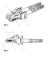
- FIG. 3 shows the two connectors 1 according to FIG. 1 in a perspective view of obliquely front and top. The connectors 1 are laterally side by side and operatively connected by means of the connector clip 3.
- FIG. 4 shows the connector according to FIG. 3 of the page.
- the connectors 1 have a main body 2 and an obliquely rearwardly elastically projecting locking arm 4 at the front end of the main body 1.
- locking arm 4 laterally projecting locking shoulders 5 are arranged for snapping into corresponding recesses a correspondingly formed socket (not shown) are used.
- a ferrule 8 At the front end of the base body 2, a ferrule 8 for receiving and for connecting an optical conductor (not shown in detail) can be seen.
- An unlocking element 6 is arranged on the base body 2. It has a sleeve (displacement element) 7, which at least partially surrounds the base body 2 and is displaceable relative thereto in the longitudinal direction (x-direction).
- the unlocking element 6 is arranged in the axial direction in front of a kink protection sleeve 19.
- a bracket 9 is arranged projecting, which is pivotally operatively connected to the locking arm 4.
- the hinged operative connection is provided by one or more thin spots 10.
- the bracket 9 may be elastically resilient or rigid.
- the thin areas 10 may be formed as film hinges.
- the bracket 9 By moving the sleeve 7 in the direction of the rear end (-x direction) of the connector 1, the bracket 9 exerts a force on the locking arm 4 and pulls it down in the direction of the main body 2. The locking shoulders 5 are thereby also moved downward so that they are unlocked and release the connector 1. The forces exerted on the collar 1 serve simultaneously to remove the connector 1 from a socket.
- Both connectors 1 have in the region of the sleeves 7 coupling means in the form of protruding elements 12, which - as in FIG. 2 shown - in accordance configured recesses 13 of an adjacent connector 1 can engage.
- the protruding elements 12 and the recesses 13 serve to connect two connectors 1 together. At the same time, they prevent unwanted relative twisting or displacement of the connectors 1.
- the connector clip 3, in the embodiment shown, has a substantially C-shaped cross-section surrounding the connectors 1 on three sides. Other one or more parts embodiments are possible.
- the connector clip 3 can - as in FIG. 3 shown - snapped in the embodiment shown from behind over the cuffs 7 of the two connectors 1, so that they are firmly connected to each other and the connector bracket 3.
- the operative connection is in the embodiment shown by corresponding snap connection means in the form of protruding elements 12 and correspondingly formed recesses 14th
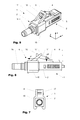
- FIG. 5 shows a connector 1 according to the invention in a view obliquely from behind and above.
- FIG. 6 shows the connector 1 according to FIG. 4 in a side view.
- FIG. 7 shows the connector in a view from behind.
- the connector 1 has a base body 2, a locking arm 4 and an unlocking element 6. At the rear end of a Crimphals 16 can be seen which serves to connect an optical cable (not shown).
- the locking arm 4 is arranged at the front end of the base body 2 obliquely rearwardly projecting above and executed resiliently.
- the locking arm 4 has on both sides of a locking shoulder 5, which serves to lock the connector 1 in a correspondingly designed socket known manner.
- the unlocking element 6 has a sleeve-like displacement element 15, which is displaceable on the base body 2 and has a bracket 17 projecting therefrom in the direction of the locking arm 4, which projects forwardly around the locking arm 4 in the region of the rear end. Due to the interaction with the ramp-like in the rear area (ramp 11) obliquely upwardly extending locking arm 4 this is pressed upon retraction of the sleeve 15 of the unlocking element 5 (arrow p1) by the bracket 17 in a defined amount down. By thereby the locking shoulders are moved downward (arrow p2) there is an unlocking of the connector.
- a mechanical stop 18 prevents the strap 17 from slipping off the locking arm 4. At the same time, the stop 18 can serve to transmit forces necessary for the removal of the connector to the locking arm 4.
- the bracket 17 is configured in the embodiment shown so that the rear end 18 of the bracket 4 remains operable from the outside and can be depressed by hand if necessary.
- the unlocking element 6 is configured in the embodiment shown as a snap element, which can be retrieved later on the connector 1.
- the sleeve (displacement element) 15 is designed to be open at the bottom.
- the cross section is designed substantially C-shaped.
- the cuff may also be, e.g. be configured closed by a flap formed by a hinge or a counter element.
- the bracket 17 may be configured so that it actively pushes the locking arm 4 in a forward position upwards and thus secures against unintentional unlocking. If necessary, the bracket 17 can be configured such that it engages in a rear position and thus holds the locking arm 4 in an unlocked position.
- the unlocking element 6 may be configured to be suitable for receiving and coordinating more than one connector.
- the displacement element 15 is designed so that more than one main body 1 can be operatively connected thereto.
- the cross section has a double C-shaped configuration, in which the two substantially C-shaped cross sections lie back to back or laterally to one another. Other embodiments are possible.
- the unlocking element is used in this case, for holding and coordinating the movements of the two connectors. The unlocking takes over in this case, the function of the connector clip 3 of the embodiment of the FIGS. 1 to 4 ,
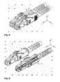
- FIG. 8 shows two connectors 1 of a third embodiment in a perspective view obliquely from above.
- FIG. 13 shows the connector 1 according to FIG. 8 in a top view.
- FIG. 14 shows a section through the arrangement of FIG. 13 along the section line AA.
- the in the FIGS. 8 and 13 two connectors 1 shown are by means of a connector bracket 20, which also serves as unlocking 6, operatively connected to each other.
- FIG. 9 shows two connectors 1 according to FIG. 8 side by side. The viewer seen from front connector 1 is partially shown in sections, so that the internal structure is better visible. In contrast to the arrangement according to FIG. 8 Each connector 1 has its own unlocking element 6. If necessary, the unlocking elements can have connection means (not shown) by means of which two unlocking elements can additionally be operatively connected to each other.
- the connectors 1 each have a base body 2, a locking arm 4 and an unlocking element 6.
- the locking arm 4 is arranged at the front end of the base body 2 obliquely rearwardly projecting above and formed in the embodiment shown resiliently (other embodiments are possible).
- the locking arm 4 has on both sides of a locking shoulder 5, which is for locking the connector 1 in a corresponding trained socket is known manner.
- the unlocking element 6 has a sliding relative to the base body 2, sleeve-like displacement element 15 with an integrally formed here in the direction of the locking arm 4 obliquely forward projecting bracket 17.
- the locking arm 4 on a thickening 21, which here forms a ramp 22 on each side of the locking arm 4, which is encompassed by the bracket 17.
- the bracket has to each side on an inwardly projecting pin 35.
- the bracket 17 respectively the pin 35 with the ramps 22 in operative connection and thereby push the rear part of the locking arm 4 due to the inclination of the ramp 22 down against the base body 2.
- the locking shoulders 5 are also pulled down, which an unlocking of the connector 1 leads.
- the chosen arrangement and design a lower design with precise guidance is possible.
- FIG. 10 is the connector according to FIG. 11 assembled shown.
- the connector according to FIG. 10 can be used without unlocking 6 if necessary. In this case, the thickening 21 at the end of the locking arm 4 is not mandatory.
- the base body 2 in the longitudinal direction on a through opening 23.
- a Ferrulenhalter 24 is inserted with a ferrule 25 from the rear end, which serve to receive a glass fiber, not shown.
- the ferrule holder 24 is pressed by a prestressed spring 26 against a shoulder 27 formed in the interior of the opening 23.
- the Ferrulenhalter has a polygonal cross-section, which cooperates positively with a correspondingly formed recess of the shoulder 27. With this configuration, the ferrule holder can be positioned for fine adjustment about its axis.
- the spring 26 is supported on a press-in sleeve 28, which is pressed into the base body 2 and, in the embodiment shown, protrudes beyond the base body 2 and at the same time serves as crimping lips.
- Similar connector constructions are known from other connectors in the prior art (see, eg US 5,984,531 ), however, these connectors belong to a different genus and build much larger, so that they have a much greater wall thickness in the sleeve. The packing density is correspondingly inferior compared to the inventive connector disclosed herein. Comparable constructions have not been considered possible in the connector class of LC connectors discussed here so far and therefore were not known. Due to the special design and tuning of the press-in sleeve 28, the required pullout values are achieved in the longitudinal direction of the connector and transversely thereto.
- the press-in sleeve 28 has a stop edge 29, which the Einpresstiefe the press-in sleeve 28 in the opening 23 of the base body 2 determined.
- the press-fit sleeve has a crimping peg 16.
- the cable sheath is pushed onto the Crimphals 16 and fixed with a crimped crimping sleeve 30.
- a not necessarily necessary for the actual function of the connector 1 anti-buckling 19 can be postponed as a conclusion on the crimping sleeve 30.
- the locking arm 4 has in the region of its connection to the base body 2 a thin point 31, which improves the elastic spring behavior when unlocking.
- the Ferrulenhalter 24 passes at the rear end in a flexibly ausgestaltetes tube 32, which protrudes in the assembled state by the spring 26 through into the press-in sleeve 28.
- a flexibly ausgestaltetes tube 32 which protrudes in the assembled state by the spring 26 through into the press-in sleeve 28.
- the required lateral mobility of the ferrule holder 24 in the interior of the main body 2 is not hindered. Nevertheless, the cable is protected from the spring 26.
- the flexible tube 29 serves as an assembly aid when needed. Another advantage is that when bonding the connector is prevented that adhesive with the spring 26 and the press-in 28 unintentionally comes into contact.
- the press-in sleeve 28 has, in the embodiment shown, two radially projecting spaced-apart ones Teeth 34, which interlock when pressed into the opening 23 in the material of the base body 2.
- the teeth 34 may have different diameters, which may increase the effect.
- the length of the active area (area that is pressed in) of the press-fit sleeve 28 corresponds to two to three times the diameter.
- no longitudinal discharge slots in the base body 2 are required in the connector disclosed here. As a result of the relaxation of the material, the teeth are securely embedded in the material of the body.
- FIG. 14 are a simple (a) and the double (b) unlocking 6 shown in a perspective view obliquely from below.
- Both unlocking elements 6 are designed as a snap element, which on one (a) or two (b) connector 1 according to FIG. 10 can be snapped.
- the sleeve (displacement element) 15 is designed to be open at the bottom.
- the cross section is substantially C-shaped, resp. Double C-shaped design. Other embodiments are possible.
- the cuff can also be designed to be closed, for example, by a flap formed by a hinge or a counter element.
- the bracket 17 may be configured so that it actively pushes the locking arm 4 in a forward position upwards and thus secures against unintentional unlocking. If necessary, the bracket 17 can be configured such that it engages in a rear position and thus holds the locking arm 4 in an unlocked position.
- the unlocking element 6 is designed so that it is suitable for receiving and coordinating more than one connector.
- the displacement element 15 is designed so that more than one main body 1 can be operatively connected.
- the cross section has a double C-shaped configuration, in which the two substantially C-shaped cross sections lie back to back or laterally to one another. Other embodiments are possible.
- the unlocking element serves in this case for holding and coordinating the movements of the two connectors.
- the connector 1 according to the FIGS. 8 to 14 allow a particularly low construction. Due to the open (non-continuous) configuration of the bracket 17 also the locking bracket 4 can be operated by hand or with a tool.
Abstract
Description
Die Erfindung liegt auf dem Gebiet der Steckverbinder, insbesondere Steckverbinder für optische Kabel.The invention is in the field of connectors, in particular connectors for optical cables.
Aus dem Stand der Technik sind Steckverbinder für optische Kabel bekannt. Ebenfalls bekannt sind so genannte LC-Verbinder. Es handelt sich dabei im weiteren Sinn um Push-Pull-Verbinder, die eine hohe Packungsdichte aufweisen. Entsprechende Verbinder werden von der Anmelderin hergestellt, sind aber auch von diversen anderen Herstellern bekannt.Connectors for optical cables are known from the prior art. Also known are so-called LC connectors. In a broader sense, these are push-pull connectors that have a high packing density. Corresponding connectors are manufactured by the applicant, but are also known by various other manufacturers.
Die europäischen Patente
Das europäische Patent
Das US-Patent
In der US-Patentanmeldung
Die US-Patente
Aus
Ein Nachteil der aus dem Stand der Technik bekannten Lösungen besteht in der ungünstigen Führung der Kräfte beim Entriegeln, beziehungsweise dem komplizierten Aufbau. Viele der bekannten Verbindern erfordern dass beim Lösen von der Buchse zwei Bewegungen - das nach unten Drücken des Auslösers und das nach hinten Ziehen des Steckverbinders - annähernd synchron erfolgen müssen. Andere Steckverbinder zeichnen sich durch einen komplizierten Aufbau auf, der sich nachteilig auf die Herstellkosten niederschlägt.A disadvantage of the known from the prior art solutions is the unfavorable leadership of the forces when unlocking, or the complicated structure. Many of the known connectors require that when loosening from the socket, two movements - pushing down the trigger and pulling the connector backwards - must occur approximately synchronously. Other connectors are characterized by a complicated structure, which is reflected adversely on the manufacturing costs.
Eine Aufgabe der Erfindung besteht darin, die Nachteile der aus dem Stand der Technik bekannten Verbinder zu überwinden. Eine weitere Aufgabe der Erfindung besteht darin, einen optischen Verbinder zu zeigen, der sich durch eine vereinfachte Bedienbarkeit auszeichnet.An object of the invention is to overcome the disadvantages of the prior art connectors. Another object of the invention is to provide an optical connector which is characterized by a simplified operability.
Die Aufgabe wird durch den in den unabhängigen Patentansprüchen definierten Verbinder gelöst.The object is achieved by the connector defined in the independent patent claims.
Im Unterschied zu den aus dem Stand der Technik bekannten Verbindern weist ein erfindungsgemässer Verbinder einen einfach herzustellenden Aufbau auf. Ausserdem werden die für die Entriegelung und die Entnahme notwendigen Kräfte so aufeinander abgestimmt, dass die Bedienung merklich erleichtert wird.In contrast to the connectors known from the prior art, a connector according to the invention has an easily manufactured construction. In addition, the forces necessary for the unlocking and removal are coordinated so that the operation is considerably facilitated.
Weitere Vorteile bestehen in der im Vergleich zu den aus dem Stand der Technik bekannten Verbindern höherer Packungsdichte, welche sich vorteilhaft auf die Anordnung auswirkt. Es können mehrere Verbinder, resp. Verbinderpaare auf engeren Raum übereinander und/oder nebeneinander angeordnet werden. Die Verbinder weisen eine geringere Bauhöhe auf. Andererseits ist die Entriegelung bei hohen Packungsdichten dennoch unproblematisch, da es nicht erforderlich ist den Entriegelungshebel wie üblich von oben her nach unten zu drücken. Einfach gesagt, sind die Finger beim Entriegeln ausserhalb des Bereichs der Verriegelungsarme.Further advantages consist in the comparison with the known from the prior art connectors higher packing density, which has an advantageous effect on the arrangement. There may be several connectors, resp. Connector pairs are arranged in a confined space one above the other and / or next to each other. The connectors have a lower height. On the other hand, the unlocking at high packing densities is still unproblematic, since it is not necessary to push the release lever as usual from above down. Simply put, when unlocked, the fingers are out of the range of the locking arms.
Verbinder der gattungsgemässen Art weisen einen weitgehend normierten Aufbau mit einem ein- oder mehrteiligen Grundkörper und einem daran angebrachten nach schräg hinten abstehenden Verriegelungsarm auf. Die Verbinder sind derart ausgestaltet, dass sie in dafür vorgesehene Buchsen eingeklinkt werden können. Seitlich am Verriegelungsarm vorstehende Verriegelungsschultern werden dabei in einen Hintergriff der Buchse eingeschnappt und verhindern damit ein ungewolltes Herausrutschen des Verbinders aus der Buchse. Der Verriegelungs-arm kann zum Entriegeln gegen den Grundkörper gedrückt werden, derart, dass die Verriegelungsschultern aus dem Hintergriff bewegt werden und so den Verbinder zur Entnahme aus der Buchse freigeben. Der Grundkörper weist eine durchgehende Öffnung auf, in der eine optische Faser angeordnet ist. Am vorderen Ende mündet die optische Faser in eine in Längsrichtung federnd gelagerte Ferrule, üblicher Weise aus Keramik. Am hinteren Ende weisen die Verbinder in der Regel einen Crimphals auf, der zum Anschluss eines Kabelmantels des optischen Kabels dient. Im Innern des Verbinders ist in der Regel eine Feder angeordnet, welche gegen einen im Bereich des hinteren Endes der Ferrule angebrachten Blocks drückt. Die Gehäuse der Verbinder werden typischer Weise aus spritzgegossenem Kunststoff hergestellt.Connectors of the generic type have a largely normalized structure with a one- or multi-part base body and an attached thereto obliquely projecting rear locking arm. The connectors are designed so that they can be latched into designated jacks. Laterally on the locking arm projecting locking shoulders are snapped into a rear handle of the socket and thus prevent accidental slipping out of the connector from the socket. The locking arm can be pressed against the base body for unlocking, such that the locking shoulders are moved out of the rear grip and thus release the connector for removal from the socket. The main body has a continuous Opening in which an optical fiber is arranged. At the front end, the optical fiber terminates in a spring-mounted ferrule, usually made of ceramic. At the rear end, the connectors typically have a crimping lip which serves to connect a cable sheath of the optical cable. In the interior of the connector, a spring is usually arranged, which presses against an attached in the region of the rear end of the ferrule block. The housings of the connectors are typically made of injection molded plastic.
Bei den aus dem Stand der Technik bekannten Verbindern muss in der Regel zum Entriegeln ein Bügel nach vorne unten gedrückt werden, bevor der Verbinder in entgegen gesetzter Richtung nach hinten aus einer Buchse entnommen werden kann. Diese Kräfteverhältnisse sind ungünstig, da während dem eine Kraft nach vorne unten, eine grössere Gegenkraft nach hinten überlagert werden muss um den Verbinder zu entriegeln und zu entnehmen.In the case of the connectors known from the prior art, a strap generally has to be pushed forwards to release it before the connector can be removed in the opposite direction to the rear from a socket. These balance of power are unfavorable, since during which a force to the front down, a greater counterforce must be superimposed to the rear to unlock the connector and remove.
Bei einer Ausführungsform der Erfindung wird dieser Nachteil vermieden, indem zum Entriegeln primär eine Kraft nach hinten - also in Entnahmerichtung - erforderlich ist. Durch diese vektorielle Gleichschaltung der Kräfte wird die Bedienung merklich vereinfacht. Konstruktiv wird dies erreicht, indem auf einem Grundkörper des Verbinders ein gegenüber diesem verschiebbares Entriegelungselement angeordnet ist, welches mit einem Verriegelungsarm wirkverbunden ist.In one embodiment of the invention, this disadvantage is avoided by primarily for unlocking a force to the rear - ie in the removal direction - is required. By this vectorial Gleichschaltung the forces, the operation is considerably simplified. In terms of design, this is achieved by arranging on a base body of the connector a release element which is displaceable relative to the latter and which is operatively connected to a locking arm.
Das Entriegelungselement weist in der Regel ein Verschiebeelement auf, das Gegenüber dem Grundkörper verschiebbar ist. Ein am Verschiebeelement angeformter oder mit diesem wirkverbundener Bügel dient zur Transformation der Bewegung des Verschiebeelementes in eine Kraft, welche zum Entriegeln des Verriegelungsbügels dient. Der Bügel ist dabei derart ausgestaltet, respektive mit dem Verriegelungsarm wirkverbunden, dass der Verbinder problemlos in eine Buchse eingeschnappt werden kann, d.h. der Verriegelungsarm kann die für die Verriegelung notwendige Bewegung in Richtung des Grundkörpers ohne grossen Aufwand und Behinderung ausführen.The unlocking element generally has a displacement element which is displaceable relative to the base body. An integrally formed on the displacement element or with this operatively connected bracket is used to transform the movement of the displacement element into a force which serves to unlock the locking bracket. The bracket is designed such, respectively operatively connected to the locking arm that the connector can be easily snapped into a socket, ie the locking arm can perform the necessary for the locking movement in the direction of the body without much effort and obstruction.
Eine Ausführungsform der Erfindung betrifft einen Steckverbinder mit einem Grundkörper und einem im Bereich des vorderen Endes des Grundkörpers angeformten, nach hinten schräg abstehenden, gelenkigen Verriegelungsarm. Ein manschettenartiges Verschiebeelement umgibt den hinteren Bereich des Grundkörpers zumindest bereichsweise und ist gegenüber diesem in Längsrichtung verschiebbar. Das Entriegelungselement ist mit dem Verriegelungsarm über einen Bügel wirkverbunden. Durch Verschieben des Entriegelungselementes in eine Entriegelungsrichtung wird, der wirkverbundene Verriegelungsarm entriegelt. Je nach Ausgestaltung und Anwendungsgebiet können der Bügel und der Verriegelungsarm und/oder der Bügel und das Verschiebeelement einteilig ausgebildet sind. Dünnstellen, z.B. in Form von Filmscharnieren, garantieren dabei die erforderliche Beweglichkeit. Je nach Ausgestaltung kann das Verschiebeelement fest oder lösbar mit dem Grundkörper wirkverbunden sein. Bei einer lösbaren Ausgestaltung kann das Verschiebeelement einen C- oder U-förmigen Querschnitt aufweist, welcher den Grundkörper teilweise umschliesst. Das Verschiebeelement kann derart ausgestaltet sein, dass es auf einem oder mehrere Verbinder gleichzeitig aufgeschnappt werden kann. Bei einer nicht lösbaren Ausgestaltung kann das Verschiebeelement einen ringförmig geschlossenen Querschnitt aufweisen, welcher den Grundkörper umgibt.An embodiment of the invention relates to a connector having a base body and an integrally formed in the region of the front end of the base, obliquely projecting rearwardly, articulated locking arm. A sleeve-like displacement element surrounds the rear region of the base body at least in regions and is displaceable relative to the latter in the longitudinal direction. The unlocking element is operatively connected to the locking arm via a bracket. By moving the unlocking element in a unlocking, the operatively connected locking arm is unlocked. Depending on the configuration and field of application of the bracket and the locking arm and / or the bracket and the displacement element are integrally formed. Thin areas, eg in the form of film hinges, guarantee the required flexibility. Depending on the configuration, the displacement element can be operatively or detachably operatively connected to the base body. In a releasable embodiment, the displacement element may have a C-shaped or U-shaped cross-section which partially encloses the base body. The sliding element may be configured such that it can be snapped on one or more connectors at the same time. In a non-detachable embodiment can the displacement element have an annular closed cross-section which surrounds the base body.
Die Entriegelungskräfte, sowie die für die Entnahme aus der Buchse erforderlichen Entnahmekräfte werden normaler Weise vom Verschiebelement über den Bügel auf den Verriegelungsarm und von da auf den Grundkörper übertragen. Durch Ziehen am Verschiebeelement wird zuerst der Verriegelungsarm entriegelt und dann der Grundkörper des Verbinders aus der Buchse gezogen. Bei Bedarf können das Verschiebeelement und/oder der Grundkörper Mittel zur Begrenzung der Verschiebung, z.B. in Form von mechanischen Anschlägen aufweisen.The Entriegelungskräfte, as well as the withdrawal forces required for removal from the socket are normally transmitted from the sliding element on the bracket on the locking arm and from there to the body. By pulling on the sliding element, first the locking arm is unlocked and then the main body of the connector is pulled out of the socket. If desired, the displacement element and / or the base body may comprise means for limiting displacement, e.g. in the form of mechanical stops.
Bei Bedarf weist der Steckverbinder Kopplungsmittel auf, die zum seitlichen Wirkverbinden mit einem weiteren Steckverbinder dienen. Je nach Anwendungsgebiet können die Kopplungsmittel am Grundkörper und/oder dem Verschiebeelement angeordnet sein. In einer Ausführungsform handelt es sich bei den Kopplungsmitteln um vorstehende Zapfen und mit ihnen korrespondierend ausgebildete Vertiefungen, die ein gegenseitiges Verdrehen der Steckverbinder verhindern.If necessary, the connector has coupling means which serve to laterally connect to another connector. Depending on the application, the coupling means may be arranged on the base body and / or the displacement element. In one embodiment, the coupling means are protruding pins and corresponding recesses formed therewith, which prevent mutual rotation of the connector.
Die Kopplungsmittel können so ausgestaltet sein, dass durch sie zwei Verbinder fest miteinander verbunden werden können. Alternativ oder in Ergänzung kann eine Halteklammer (Verbinderklammer) vorgesehen werden, die zur Aufnahme von zwei oder mehreren Verbindern geeignet ist. Die Halteklammer kann zum gemeinsamen Entriegeln der Verbinder geeignet sein.The coupling means may be designed so that two connectors can be firmly connected to each other by them. Alternatively or in addition, a retaining clip (connector clip) can be provided, which is suitable for receiving two or more connectors. The retaining clip may be suitable for unlocking the connectors together.
Wie schon oben erwähnt ist aus
Die Erfindung soll anhand der in den nachfolgenden Figuren gezeigten Ausführungsbeispiele näher erläutert werden. Es zeigen
- Fig. 1
- zwei Exemplare einer ersten Ausführungsform eines Steckverbinders in einer perspektivischen Darstellung von schräg vorne und oben;
- Fig. 2
- zwei neben einander angeordnete Steckverbinder gemäss
Figur 1 und eine Verbindeklammer in einer perspektivischen Ansicht von schräg vorne und oben; - Fig. 3
- die
Steckverbinder gemäss Figur 2 mit wirkverbundener Verbindeklammer in einer perspektivischen Ansicht von schräg vorne und oben; - Fig. 4
- die
Steckverbinder gemäss Figur 3 in einer Seitenansicht; - Fig. 5
- eine zweite Ausführungsform eines Steckverbinders in einer perspektivischen Ansicht von schräg hinten;
- Fig. 6
- den
Steckverbinder gemäss Figur 5 von der Seite; - Fig. 7
- den
Steckverbinder gemäss Figur 5 von hinten; - Fig. 8
- zwei weitere Steckverbinder von schräg oben und miteinander wirkverbunden;
- Fig. 9
- die beiden Steckverbinder gemäss
Figur 8 in getrennter Darstellung und teilweise geschnitten; - Fig. 10
- einen Steckverbinder gemäss
Figur 8 ohne Entriegelungselement; - Fig. 11
- einen Steckverbinder gemäss
Figur 8 in einer Explosionsdarstellung; - Fig. 12
- ein Entriegelungselement für einen Verbinder und ein Entriegelungs-element für zwei Verbinder;
- Fig. 13
- die beiden Verbinder gemäss
Figur 8 in einer Draufsicht; - Fig. 14
- eine Schnittdarstellung entlang der Schnittlinie
AA gemäss Figur 13 .
- Fig. 1
- two copies of a first embodiment of a connector in a perspective view obliquely from the front and top;
- Fig. 2
- two connectors arranged side by side according to
FIG. 1 and a connecting bracket in a perspective view obliquely from the front and from the top; - Fig. 3
- the connectors according to
FIG. 2 with operatively connected connecting bracket in a perspective view obliquely from the front and from the top; - Fig. 4
- the connectors according to
FIG. 3 in a side view; - Fig. 5
- a second embodiment of a connector in a perspective view obliquely from behind;
- Fig. 6
- according to the connector
FIG. 5 of the page; - Fig. 7
- according to the connector
FIG. 5 from the back; - Fig. 8
- two other connectors from above obliquely and operatively connected to each other;
- Fig. 9
- the two connectors according to
FIG. 8 in separate and partially cut; - Fig. 10
- a connector according to
FIG. 8 without unlocking element; - Fig. 11
- a connector according to
FIG. 8 in an exploded view; - Fig. 12
- an unlocking element for a connector and an unlocking element for two connectors;
- Fig. 13
- the two connectors according to
FIG. 8 in a plan view; - Fig. 14
- a sectional view along the section line AA according to
FIG. 13 ,
Sich entsprechende Elemente sind in den Figuren mit identischen Bezugszeichen versehen.Corresponding elements are provided in the figures with identical reference numerals.
Die Verbinder 1 weisen einen Grundkörper 2 und einen am vorderen Ende des Grundkörpers 1 schräg nach hinten elastisch federnd abstehenden Verriegelungsarm 4 auf. Am Verriegelungsarm 4 sind seitlich vorstehende Verriegelungsschultern 5 angeordnet die zum Einschnappen in entsprechende Ausnehmungen einer korrespondierend ausgebildeten Buchse (nicht dargestellt) dienen. Am vorderen Ende des Grundkörpers 2 ist eine Ferrule 8 zur Aufnahme und zum Verbinden eines optischen Leiters (nicht näher dargestellt) zu erkennen.The
Ein Entriegelungselement 6 ist auf dem Grundkörper 2 angeordnet. Es weist eine Manschette (Verschiebelement) 7 auf, welche den Gründkörper 2 zumindest teilweise umgibt und gegenüber diesem in Längsrichtung (x-Richtung) verschiebbar ist. Das Entriegelungselement 6 ist in axialer Richtung vor einer Knickschutzhülle 19 angeordnet.An unlocking
An der Manschette 7 ist ein Bügel 9 vorstehend angeordnet, der mit dem Verriegelungsarm 4 gelenkig wirkverbunden ist. In der gezeigten Ausführungsform ist die gelenkige Wirkverbindung durch eine oder mehrere Dünnstellen 10 gegeben. Je nach Ausführungsform kann der Bügel 9 elastisch federnd oder starr ausgebildet sein. Die Dünnstellen 10 können als Filmscharniere ausgebildet sein.On the
Durch Verschieben der Manschette 7 in Richtung des hinteren Endes (-x-Richtung) des Verbinders 1 wirkt der Bügel 9 eine Kraft auf den Verriegelungsarm 4 aus und zieht diesen nach unten in Richtung des Grundkörpers 2. Die Verriegelungsschultern 5 werden dadurch ebenfalls nach unten verschoben, so dass sie entriegelt werden und den Verbinder 1 freigeben. Die auf die Manschette 1 ausgeübten Kräfte dienen gleichzeitig zur Entnahme des Verbinders 1 aus einer Buchse.By moving the
Beide Verbinder 1 weisen im Bereich der Manschetten 7 Kopplungsmittel in Form von vorstehenden Elemente 12 auf, die - wie in
In dem die Verbinderklammer 3, wie in
Der Steckverbinder 1 weist einen Grundkörper 2, einen Verriegelungsarm 4 und ein Entriegelungselement 6 auf. Am hinteren Ende ist ein Crimphals 16 zu erkennen der zum Anschliessen eine optischen Kabels (nicht näher dargestellt) dient.The
Der Verriegelungsarm 4 ist am vorderen Ende des Grundkörpers 2 schräg nach hinten oben abstehend angeordnet und elastisch federnd ausgeführt. Der Verriegelungsarm 4 weist beidseits eine Verriegelungsschulter 5 auf, die zur Verriegelung des Steckverbinders 1 in einer korrespondierend ausgebildeten Buchse bekannter Art und Weise dient.The locking
Das Entriegelungselement 6 weist in der gezeigten Ausführungsform ein auf dem Grundkörper 2 verschiebbares, manschettenartiges Verschiebelement 15 mit einem daran angeformten hier in Richtung des Verriegelungsarmes 4 schrägt nach vorne vorstehenden Bügel 17 auf, welcher den Verriegelungsarm 4 im Bereich des hinteren Endes umgibt. Durch das Zusammenwirken mit dem im hinteren Bereich rampenartig (Rampe 11) schräg nach oben verlaufenden Verriegelungsarm 4 wird dieser beim Zurückziehen der Manschette 15 des Entriegelungselementes 5 (Pfeil p1) durch den Bügel 17 in einem definierten Mass nach unten gedrückt. Indem dadurch die Verriegelungsschultern nach unten bewegt werden (Pfeil p2) erfolgt eine Entriegelung des Verbinders. In der gezeigten Ausführungsform verhindert ein mechanischer Anschlag 18 ein Abrutschen des Bügels 17 vom Verriegelungsarm 4. Gleichzeitig kann der Anschlag 18 dazu dienen, für die Entnahme des Verbinders notwendigen Kräfte auf den Verriegelungsarm 4 zu übertragen. Der Bügel 17 ist in der gezeigten Ausführungsform derart ausgestaltet, dass das hintere Ende 18 des Bügel 4 von aussen bedienbar bleibt und bei Bedarf von Hand niedergedrückt werden kann.In the embodiment shown, the unlocking
Wie in
Zu diesem Zweck ist die Manschette (Verschiebeelement) 15 im unteren Bereich offen ausgestaltet. Der Querschnitt ist im Wesentlichen C-förmig ausgestaltet. Andere Ausgestaltungen sind möglich. Die Manschette kann aber auch, z.B. durch eine über ein Scharnier angeformte Klappe oder ein Gegenelement geschlossen ausgestaltet sein. Der Bügel 17 kann so ausgestaltet sein, dass er den Verriegelungsarm 4 in einer vorderen Position aktiv nach oben drückt und damit gegen ungewolltes Entriegeln sichert. Bei Bedarf kann der Bügel 17 derart ausgestaltet sein, dass er in einer hinteren Position einrastet und damit den Verriegelungsarm 4 in einer entriegelten Position festhält.For this purpose, the sleeve (displacement element) 15 is designed to be open at the bottom. The cross section is designed substantially C-shaped. Other embodiments are possible. The cuff may also be, e.g. be configured closed by a flap formed by a hinge or a counter element. The
Bei Bedarf kann das Entriegelungselement 6 so ausgestaltet sein, dass es zur Aufnahme und Koordination von mehr als einem Verbinder geeignet ist. In diesem Fall ist das Verschiebeelement 15 so ausgestaltet, dass mehr als ein Grundkörper 1 damit wirkverbunden werden können. In einer Ausführungsform weist der Querschnitt eine doppel-C-förmige Ausgestaltung auf, bei dem die beiden im Wesentlichen C-förmigen Querschnitte Rücken an Rücken oder seitlich aneinander liegen. Andere Ausgestaltungen sind möglich. Das Entriegelungselement dient in diesem Fall zur Halterung und zur Koordination der Bewegungen der beiden Verbinder. Das Entriegelungselement übernimmt in diesem Fall die Funktion der Verbinderklammer 3 des Ausführungsbeispiels aus den
Die Steckverbinder 1 weisen je einen Grundkörper 2, einen Verriegelungsarm 4 und ein Entriegelungselement 6 auf. Der Verriegelungsarm 4 ist am vorderen Ende des Grundkörpers 2 schräg nach hinten oben abstehend angeordnet und in der gezeigten Ausführungsform elastisch federnd ausgebildet (andere Ausgestaltungen sind möglich). Der Verriegelungsarm 4 weist beidseits eine Verriegelungsschulter 5 auf, die zur Verriegelung des Steckverbinders 1 in einer korrespondierend ausgebildeten Buchse bekannter Art und Weise dient. Das Entriegelungselement 6 weist ein gegenüber dem Grundkörper 2 verschiebbares, manschettenartiges Verschiebelement 15 mit einem daran angeformten hier in Richtung des Verriegelungsarmes 4 schrägt nach vorne vorstehenden Bügel 17 auf. Am hinteren Ende weist der Verriegelungsarm 4 eine Verdickung 21 auf, die hier auf jeder Seite des Verriegelungsarmes 4 eine Rampe 22 bildet, welche vom Bügel 17 umgriffen wird. Der Bügel weist dazu pro Seite einen nach innen vorstehenden Zapfen 35 auf. Zum Entriegeln wird das Entriegelungselement 6 auf dem Grundkörper 2, z.B. mit Daumen und Zeigefinger, nach hinten (-x-Richtung) gezogen. Dadurch tritt der Bügel 17, respektive die Zapfen 35 mit den Rampen 22 in Wirkverbindung und drücken dadurch den hinteren Teil des Verriegelungsarmes 4 aufgrund der Neigung der Rampe 22 nach unten gegen den Grundkörper 2. Dadurch werden die Verriegelungsschultern 5 ebenfalls nach unten gezogen, was zu einer Entriegelung des Verbinders 1 führt. Durch die gewählte Anordnung und Ausgestaltung ist eine niedere Bauform mit präziser Führung möglich.The
In den
Wie in den
Wie in den
In der Schnittdarstellung gemäss
Der Ferrulenhalter 24 geht am hinteren Ende in ein flexibel ausgestaltetes Rohr 32 über, welches in montiertem Zustand durch die Feder 26 hindurch bis in die Einpresshülse 28 hineinragt. Durch diese Ausgestaltung wird die erforderliche seitliche Beweglichkeit des Ferrulenhalters 24 im Innern des Grundkörpers 2 nicht behindert. Dennoch wird das Kabel gegenüber der Feder 26 geschützt. Des Weiteren dient das flexible Rohr 29 bei Bedarf als Montagehilfe. Ein weiterer Vorteil besteht darin, dass beim Verkleben des Verbinders verhindert wird, dass Klebstoff mit der Feder 26 und der Einpresshülse 28 ungewollt in Verbindung kommt.The Ferrulenhalter 24 passes at the rear end in a flexibly
Wie in
In
In
Die Verbinder 1 gemäss den
Claims (15)
einen Grundkörper (2) mit einer durchgehenden Öffnung, in der eine optische Faser angeordnet ist, die am vorderen Ende des Grundkörpers (2) in eine in Längsrichtung federnd gelagerte Ferrule mündet, und
einem am vorderen Ende des Grundkörpers (2) angeformten, nach hinten schräg abstehenden, gelenkigen Verriegelungsarm (4); weiter umfassend
ein auf dem Grundkörper (2) angeordnetes und gegenüber diesem verschiebbares Entriegelungselement (6), welches mit dem Verriegelungsarm (4) wirkverbunden ist;
wobei das Entriegelungselement (6) ein gegenüber dem Grundkörper (2) verschiebbares Verschiebeelement (15) und ein am Verschiebeelement (15) angeformten Bügel (17) aufweist,
wobei das Verschiebeelement (15) und der Verriegelungsarm (4) über den Bügel (17) wirkverbunden sind,
und wobei der am Verschiebeelement (15) angeformte Bügel (17) in Richtung des Verriegelungsarms (4) schräg nach vorne vorsteht.Optical connector (1) comprising
a base body (2) having a through hole in which an optical fiber is arranged, which opens at the front end of the base body (2) in a longitudinally spring-mounted ferrule, and
a at the front end of the base body (2) integrally formed, rearwardly projecting obliquely, articulated locking arm (4); further comprising
an unlocking element (6) arranged on the base body (2) and displaceable relative thereto, which is operatively connected to the locking arm (4);
wherein the unlocking element (6) has a sliding element (15) displaceable relative to the base body (2) and a bracket (17) integrally formed on the displacement element (15),
wherein the displacement element (15) and the locking arm (4) are operatively connected via the bracket (17),
and wherein the bracket (17) integrally formed on the displacement element (15) protrudes obliquely forwards in the direction of the locking arm (4).
Priority Applications (1)
| Application Number | Priority Date | Filing Date | Title |
|---|---|---|---|
| EP16173809.1A EP3101456B1 (en) | 2008-05-07 | 2009-04-28 | Plug connector having unlocking mechanism |
Applications Claiming Priority (2)
| Application Number | Priority Date | Filing Date | Title |
|---|---|---|---|
| CH7072008 | 2008-05-07 | ||
| EP09742005.3A EP2274644B1 (en) | 2008-05-07 | 2009-04-28 | Optical plug connector having unlocking mechanism |
Related Parent Applications (2)
| Application Number | Title | Priority Date | Filing Date |
|---|---|---|---|
| EP09742005.3A Division-Into EP2274644B1 (en) | 2008-05-07 | 2009-04-28 | Optical plug connector having unlocking mechanism |
| EP09742005.3A Division EP2274644B1 (en) | 2008-05-07 | 2009-04-28 | Optical plug connector having unlocking mechanism |
Related Child Applications (1)
| Application Number | Title | Priority Date | Filing Date |
|---|---|---|---|
| EP16173809.1A Division EP3101456B1 (en) | 2008-05-07 | 2009-04-28 | Plug connector having unlocking mechanism |
Publications (2)
| Publication Number | Publication Date |
|---|---|
| EP2664951A1 true EP2664951A1 (en) | 2013-11-20 |
| EP2664951B1 EP2664951B1 (en) | 2016-06-15 |
Family
ID=40886679
Family Applications (3)
| Application Number | Title | Priority Date | Filing Date |
|---|---|---|---|
| EP13180091.4A Active EP2664951B1 (en) | 2008-05-07 | 2009-04-28 | Plug connector having unlocking mechanism |
| EP09742005.3A Active EP2274644B1 (en) | 2008-05-07 | 2009-04-28 | Optical plug connector having unlocking mechanism |
| EP16173809.1A Active EP3101456B1 (en) | 2008-05-07 | 2009-04-28 | Plug connector having unlocking mechanism |
Family Applications After (2)
| Application Number | Title | Priority Date | Filing Date |
|---|---|---|---|
| EP09742005.3A Active EP2274644B1 (en) | 2008-05-07 | 2009-04-28 | Optical plug connector having unlocking mechanism |
| EP16173809.1A Active EP3101456B1 (en) | 2008-05-07 | 2009-04-28 | Plug connector having unlocking mechanism |
Country Status (5)
| Country | Link |
|---|---|
| US (1) | US8221007B2 (en) |
| EP (3) | EP2664951B1 (en) |
| CN (2) | CN102016670B (en) |
| DK (1) | DK2664951T3 (en) |
| WO (1) | WO2009135787A1 (en) |
Cited By (3)
| Publication number | Priority date | Publication date | Assignee | Title |
|---|---|---|---|---|
| DE202016103178U1 (en) | 2016-06-16 | 2016-07-07 | Reichle & De-Massari Ag | Connectors |
| US11422313B2 (en) | 2017-05-25 | 2022-08-23 | Senko Advanced Components, Inc. | Adjustable polarity fiber optic connector assemblies with push-pull tabs |
| US11500164B2 (en) | 2018-09-12 | 2022-11-15 | Senko Advanced Components, Inc. | LC type connector with push/pull assembly for releasing connector from a receptacle using a cable boot |
Families Citing this family (115)
| Publication number | Priority date | Publication date | Assignee | Title |
|---|---|---|---|---|
| US8408815B2 (en) | 2009-06-18 | 2013-04-02 | Senko Advanced Components, Inc. | Optical fiber connector and adapter |
| US20110081113A1 (en) * | 2009-10-02 | 2011-04-07 | Jones Ashley W | Fiber Optic Connector Assembly and Methods Therefor |
| ES2395358B1 (en) | 2011-02-08 | 2014-04-25 | Tyco Electronics Corporation | SINGLE ACTION CONNECTOR |
| ES2402632B1 (en) * | 2011-02-08 | 2014-05-14 | Tyco Electronics Raychem Bvba | RELEASE TONGUE FOR AN ELECTRICAL CONNECTOR AND ELECTRICAL CONNECTOR THAT INCLUDES SUCH RELEASE TONGUE |
| EP2705395B1 (en) | 2011-05-04 | 2020-01-08 | The Siemon Company | Fiber optic connector with polarity change |
| US9188747B2 (en) | 2011-05-23 | 2015-11-17 | Senko Advanced Components, Inc. | True one piece housing fiber optic adapter |
| US8764308B2 (en) | 2011-06-06 | 2014-07-01 | Panduit Corp. | Duplex clip assembly for fiber optic connectors |
| US8465317B2 (en) | 2011-10-05 | 2013-06-18 | Senko Advanced Components, Inc. | Latching connector with remote release |
| US8348686B1 (en) * | 2011-10-11 | 2013-01-08 | Li-Ping Huang | Plug security structure for electrical connector |
| DE202011052551U1 (en) * | 2011-12-31 | 2012-05-22 | Zellner Gmbh | Plug for a data cable |
| EP2615695B1 (en) * | 2012-01-16 | 2016-02-24 | Tibor Kovacs | Connector for a data cable and method for its production |
| CN103257407B (en) * | 2012-02-20 | 2015-11-25 | 泰科电子(上海)有限公司 | Connector and connector assembly |
| US8974124B2 (en) | 2012-08-16 | 2015-03-10 | Senko Advanced Components, Inc. | Fiber optic connector |
| EP2796908A1 (en) * | 2013-04-24 | 2014-10-29 | Euromicron Werkzeuge GmbH | Optical plug-in connection with high density packaging |
| US9268103B2 (en) | 2013-05-10 | 2016-02-23 | Senko Advanced Components, Inc. | Interlockable fiber optic connector adaptors |
| US9360649B2 (en) | 2013-05-22 | 2016-06-07 | Senko Advanced Components, Inc. | Cable guide for fiber optic cables |
| TWI486657B (en) * | 2013-07-10 | 2015-06-01 | Advanced Connetek Inc | Optic fiber connector |
| US9618703B2 (en) | 2013-10-03 | 2017-04-11 | Senko Advanced Components, Inc. | Connector housing for securing an optical cable and methods of use and manufacture thereof |
| EP3067724B1 (en) * | 2013-11-08 | 2020-11-04 | Honda Tsushin Kogyo Co., Ltd | Optical connector plug |
| US9477049B2 (en) | 2013-12-20 | 2016-10-25 | Senko Advanced Components, Inc. | Lockable connectors and connection assemblies |
| ES2879918T3 (en) | 2014-01-13 | 2021-11-23 | Commscope Telecommunications Shanghai Co Ltd | Fiber optic connector |
| US20160154190A1 (en) * | 2014-01-28 | 2016-06-02 | Jyh Eng Technology Co., Ltd. | Duplex fiber optic connector plug |
| CN104808296B (en) | 2014-01-28 | 2016-08-17 | 智英科技股份有限公司 | Duplex optical fiber connector plug |
| US9535230B2 (en) | 2014-01-31 | 2017-01-03 | Senko Advanced Components, Inc. | Integrated fiber optic cable fan-out connector |
| JP6247576B2 (en) * | 2014-03-24 | 2017-12-13 | 日本航空電子工業株式会社 | Connector, plug with built-in connector |
| US9297964B2 (en) | 2014-04-18 | 2016-03-29 | Senko Advanced Components, Inc. | Optical fiber connector assembly |
| US9274287B2 (en) | 2014-05-13 | 2016-03-01 | Senko Advanced Components, Inc. | Optical fiber connector and ferrule |
| US10495824B2 (en) | 2014-05-16 | 2019-12-03 | Joel C. Rosson | Optical connector element |
| US9618702B2 (en) | 2014-06-09 | 2017-04-11 | Senko Advanced Components, Inc. | Reduced-profile data transmission element connectors, adapters, and connection assemblies thereof |
| CN104332761B (en) * | 2014-08-29 | 2018-01-16 | 中航光电科技股份有限公司 | Long unblock communication network interface plug and ethernet connector |
| DE102014113151A1 (en) * | 2014-09-12 | 2016-05-12 | Eugen Forschner Gmbh | Locking element for a connector |
| US9599778B2 (en) | 2014-10-22 | 2017-03-21 | Senko Advanced Components, Inc. | Latching connector with remote release |
| EP3218968B1 (en) | 2014-11-11 | 2020-06-10 | Huber+Suhner Ag | Connector assembly |
| US9494745B2 (en) | 2015-01-16 | 2016-11-15 | Senko Advanced Components, Inc. | Sealable communication cable connection assemblies |
| US9658409B2 (en) | 2015-03-03 | 2017-05-23 | Senko Advanced Components, Inc. | Optical fiber connector with changeable polarity |
| CN204595258U (en) | 2015-04-20 | 2015-08-26 | 连展科技电子(昆山)有限公司 | Can the Optical fiber plug connector of quick release |
| US9739955B2 (en) | 2015-05-07 | 2017-08-22 | Alliance Fiber Optic Products, Inc. | Push-pull type fiber optic connector assembly |
| CN105140719B (en) * | 2015-05-27 | 2018-08-10 | 中航光电科技股份有限公司 | Pull the optical connector and electric connector of unlock |
| US9684139B2 (en) | 2015-05-29 | 2017-06-20 | Senko Advanced Components, Inc. | Optical fiber connector with changeable gender |
| USD830304S1 (en) * | 2015-06-23 | 2018-10-09 | A. J. World Co., Ltd. | Optical connector for optical fiber |
| DE102015122862B4 (en) | 2015-11-25 | 2022-08-11 | Tianjin Geneuo Technology Co., Ltd. | Ethernet connector with unlocking function |
| WO2017123247A1 (en) * | 2016-01-15 | 2017-07-20 | Senko Advanced Components, Inc. | Narrow width adapters and connectors with spring loaded remote release |
| US10158194B2 (en) | 2016-01-15 | 2018-12-18 | Senko Advanced Components, Inc. | Narrow width adapters and connectors with spring loaded remote release |
| US9595786B1 (en) | 2016-01-15 | 2017-03-14 | Senko Advanced Components, Inc. | Narrow width adapters and connectors with spring loaded remote release |
| US9933584B2 (en) * | 2016-02-03 | 2018-04-03 | Jyh Eng Technology Co., Ltd. | Duplex fiber optic connector plug with angles actuated latching |
| USD803163S1 (en) * | 2016-05-13 | 2017-11-21 | Erico International Corporation | Tip receptor mount for lightning protection systems |
| WO2017218342A1 (en) * | 2016-06-13 | 2017-12-21 | Corning Optical Communications LLC | Connector with trigger locking feature, and cable assemblies and methods including the same |
| US9726830B1 (en) | 2016-06-28 | 2017-08-08 | Senko Advanced Components, Inc. | Connector and adapter system for two-fiber mechanical transfer type ferrule |
| WO2018006987A1 (en) | 2016-07-08 | 2018-01-11 | Huber+Suhner Ag | Optical connector |
| US9829653B1 (en) | 2016-09-12 | 2017-11-28 | Senko Advanced Components, Inc. | Optical connector and adapter system for a dual-ferrule connector |
| US10228521B2 (en) | 2016-12-05 | 2019-03-12 | Senko Advanced Components, Inc. | Narrow width adapters and connectors with modular latching arm |
| US10078188B1 (en) | 2016-12-05 | 2018-09-18 | Senko Advanced Components, Inc. | Springless push/pull fiber optic connector |
| MX2019006360A (en) * | 2016-12-06 | 2019-08-21 | Raytheon Co | Connector removal tool. |
| US10416394B2 (en) | 2017-01-30 | 2019-09-17 | Senko Advanced Components, Inc. | Fiber optic receptacle with integrated device therein |
| US10185100B2 (en) | 2017-01-30 | 2019-01-22 | Senko Advanced Components, Inc | Modular connector and adapter assembly using a removable anchor device |
| US10444444B2 (en) | 2017-01-30 | 2019-10-15 | Senko Advanced Components, Inc. | Remote release tab connector assembly |
| WO2018140981A1 (en) | 2017-01-30 | 2018-08-02 | Senko Advanced Components, Inc. | Optical connectors with reversible polarity |
| US11333836B2 (en) | 2017-01-30 | 2022-05-17 | Senko Advanced Components, Inc. | Adapter for optical connectors |
| US10725248B2 (en) | 2017-01-30 | 2020-07-28 | Senko Advanced Components, Inc. | Fiber optic receptacle with integrated device therein incorporating a behind-the-wall fiber optic receptacle |
| US9989712B1 (en) | 2017-03-20 | 2018-06-05 | Senko Advanced Components, Inc | MPO connector assembly with push-pull tab |
| US10209461B2 (en) | 2017-04-07 | 2019-02-19 | Senko Advanced Components | Behind the wall optical connector with reduced components |
| US10989884B2 (en) | 2017-04-07 | 2021-04-27 | Senko Advanced Components, Inc. | Behind the wall optical connector with reduced components |
| US10754098B2 (en) | 2017-04-07 | 2020-08-25 | Senko Advanced Components, Inc. | Behind the wall optical connector with reduced components |
| US10359583B2 (en) | 2017-04-07 | 2019-07-23 | Senko Advanced Components, Inc. | Behind the wall optical connector with reduced components |
| US10718910B2 (en) | 2017-05-03 | 2020-07-21 | Senko Advanced Components, Inc | Field terminated ruggedized fiber optic connector system |
| US10146016B1 (en) | 2017-05-10 | 2018-12-04 | Senko Advanced Components, Inc | MPO micro-latchlock connector |
| US10401576B2 (en) | 2017-05-10 | 2019-09-03 | Senko Advanced Components, Inc. | MPO micro-latch-lock connector |
| US10295759B2 (en) | 2017-05-18 | 2019-05-21 | Senko Advanced Components, Inc. | Optical connector with forward-biasing projections |
| US10663676B2 (en) | 2017-05-25 | 2020-05-26 | Senko Advanced Components, Inc | Adjustable polarity fiber optic connector assemblies with push-pull tabs |
| WO2018226959A1 (en) | 2017-06-07 | 2018-12-13 | Commscope Technologies Llc | Fiber optic adapter and cassette |
| US10359576B2 (en) | 2017-06-15 | 2019-07-23 | Senko Advanced Components, Inc. | SC low profile connector with optional boot |
| US9941631B1 (en) | 2017-06-29 | 2018-04-10 | Seikoh Giken Co., Ltd. | Plug and cable with plug |
| US10718911B2 (en) | 2017-08-24 | 2020-07-21 | Senko Advanced Components, Inc. | Ultra-small form factor optical connectors using a push-pull boot receptacle release |
| US11822133B2 (en) | 2017-07-14 | 2023-11-21 | Senko Advanced Components, Inc. | Ultra-small form factor optical connector and adapter |
| US10705300B2 (en) | 2017-07-14 | 2020-07-07 | Senko Advanced Components, Inc. | Small form factor fiber optic connector with multi-purpose boot assembly |
| US10838152B2 (en) | 2017-11-17 | 2020-11-17 | Senko Advanced Components, Inc. | Ultra-small form factor optical connector having dual alignment keys |
| US10281668B2 (en) | 2017-07-14 | 2019-05-07 | Senko Advanced Components, Inc. | Ultra-small form factor optical connectors |
| CN109411943A (en) * | 2017-08-17 | 2019-03-01 | 富士康(昆山)电脑接插件有限公司 | Pin connector mould group |
| US10641972B2 (en) | 2017-08-17 | 2020-05-05 | Senko Advanced Components, Inc | Anti-jam alignment sleeve holder or connector housing for a ferrule assembly |
| WO2019038641A1 (en) * | 2017-08-24 | 2019-02-28 | Senko Advanced Components, Inc. | Ultra-small form factor optical connectors using a push-pull boot receptacle release |
| WO2019055820A1 (en) | 2017-09-15 | 2019-03-21 | Commscope Technologies Llc | Fiber optic connector with boot-integrated release and related assemblies |
| US10444442B2 (en) | 2017-11-03 | 2019-10-15 | Senko Advanced Components, Inc. | MPO optical fiber connector |
| US10830963B2 (en) | 2017-11-17 | 2020-11-10 | Commscope Technologies Llc | Fiber optic connector locking feature |
| US11002923B2 (en) | 2017-11-21 | 2021-05-11 | Senko Advanced Components, Inc. | Fiber optic connector with cable boot release having a two-piece clip assembly |
| CN107976750A (en) * | 2017-12-13 | 2018-05-01 | 深圳市飞博康光通讯技术有限公司 | A kind of optical fiber connector |
| US10678000B2 (en) | 2018-01-05 | 2020-06-09 | Senko Advanced Components, Inc. | Pull rod and alignment key for a fiber optic connector and adapter |
| DE102018200886B3 (en) * | 2018-01-19 | 2019-07-04 | Te Connectivity Germany Gmbh | Method for monitoring an electric current flow |
| WO2019183070A2 (en) | 2018-03-19 | 2019-09-26 | Senko Advanced Components, Inc. | Removal tool for removing a plural of micro optical connectors from an adapter interface |
| USD897959S1 (en) * | 2018-04-06 | 2020-10-06 | Huber+Suhner Ag | Connecting plug for a fiber optic cable end |
| US11041993B2 (en) | 2018-04-19 | 2021-06-22 | Senko Advanced Components, Inc. | Fiber optic adapter with removable insert for polarity change and removal tool for the same |
| USD892742S1 (en) * | 2018-06-04 | 2020-08-11 | Acon Optics Communications Inc. | Optical fiber connector |
| US10921528B2 (en) | 2018-06-07 | 2021-02-16 | Senko Advanced Components, Inc. | Dual spring multi-fiber optic connector |
| US10852490B2 (en) * | 2018-06-10 | 2020-12-01 | Senko Advanced Components, Inc. | Fiber optic connector clip |
| CN112088327A (en) | 2018-07-15 | 2020-12-15 | 扇港元器件股份有限公司 | Ultra-small optical connector and adapter |
| US10444441B1 (en) | 2018-08-10 | 2019-10-15 | Senko Advanced Components, Inc. | Pivotable housing for a fiber optic connector |
| US11073664B2 (en) | 2018-08-13 | 2021-07-27 | Senko Advanced Components, Inc. | Cable boot assembly for releasing fiber optic connector from a receptacle |
| US11086087B2 (en) | 2018-09-12 | 2021-08-10 | Senko Advanced Components, Inc. | LC type connector with clip-on push/pull tab for releasing connector from a receptacle using a cable boot |
| US10921530B2 (en) | 2018-09-12 | 2021-02-16 | Senko Advanced Components, Inc. | LC type connector with push/pull assembly for releasing connector from a receptacle using a cable boot |
| US11806831B2 (en) | 2018-11-21 | 2023-11-07 | Senko Advanced Components, Inc. | Fixture and method for polishing fiber optic connector ferrules |
| US11175464B2 (en) | 2018-11-25 | 2021-11-16 | Senko Advanced Components, Inc. | Open ended spring body for use in an optical fiber connector |
| CN209373180U (en) | 2018-12-13 | 2019-09-10 | 连讯通信(天津)有限公司 | Optical fiber connector |
| CN109610222B (en) * | 2018-12-14 | 2020-09-22 | 维美德(中国)有限公司 | Connector and toilet paper machine |
| US11689247B2 (en) | 2019-01-16 | 2023-06-27 | Mertek Industries, Llc | Patch cord including wireless components |
| WO2020198755A1 (en) | 2019-03-28 | 2020-10-01 | Senko Advanced Components, Inc | Fiber optic adapter assembly |
| TWM600397U (en) | 2019-04-11 | 2020-08-21 | 連訊通信股份有限公司 | Optical fiber connector |
| CN209928065U (en) | 2019-04-11 | 2020-01-10 | 连讯通信(天津)有限公司 | Optical fiber connector |
| US11340406B2 (en) | 2019-04-19 | 2022-05-24 | Senko Advanced Components, Inc. | Small form factor fiber optic connector with resilient latching mechanism for securing within a hook-less receptacle |
| JP7036772B2 (en) | 2019-05-27 | 2022-03-15 | 矢崎総業株式会社 | Optical connector |
| WO2020252355A1 (en) | 2019-06-13 | 2020-12-17 | Senko Advanced Components, Inc | Lever actuated latch arm for releasing a fiber optic connector from a receptacle port and method of use |
| US11467354B2 (en) | 2019-07-23 | 2022-10-11 | Senko Advanced Components, Inc. | Ultra-small form factor receptacle for receiving a fiber optic connector opposing a ferrule assembly |
| CN114787677A (en) | 2019-11-13 | 2022-07-22 | 扇港元器件有限公司 | Optical fiber connector |
| WO2021243076A1 (en) * | 2020-05-29 | 2021-12-02 | Commscope Technologies Llc | Telecommunications connector with latch release mechanism |
| JP2022107105A (en) * | 2021-01-08 | 2022-07-21 | 住友電装株式会社 | Connector and connector device |
| US11934017B2 (en) | 2021-03-02 | 2024-03-19 | Corning Research & Development Corporation | Polarity changeable optical connector |
| WO2022216861A1 (en) * | 2021-04-08 | 2022-10-13 | Commscope Technologies Llc | Telecommunications connector with latch release mechanism |
Citations (13)
| Publication number | Priority date | Publication date | Assignee | Title |
|---|---|---|---|---|
| JPS63184271A (en) * | 1987-01-27 | 1988-07-29 | 松下電工株式会社 | Modular plug |
| US5481634A (en) | 1994-06-24 | 1996-01-02 | At&T Corp. | Connector for optical fiber |
| US5579425A (en) | 1995-08-30 | 1996-11-26 | Lucent Technologies Inc. | Anti-snag duplex connector |
| US5984531A (en) | 1997-05-20 | 1999-11-16 | Adc Telecommunications, Inc. | Fiber connector and adapter |
| EP0762558B1 (en) | 1995-08-30 | 2000-11-15 | AT&T Corp. | Anti-snag latch assembly for a connector |
| US6206581B1 (en) | 1999-10-06 | 2001-03-27 | Lucent Technologies Inc. | Optical connector having a one-piece housing |
| US6565262B2 (en) | 2000-12-14 | 2003-05-20 | Corning Cable Systems Llc | Trigger mechanism, optical cable connector including same, and method of assembling an optical cable connector |
| EP1091227B1 (en) | 1999-10-06 | 2004-05-12 | Lucent Technologies Inc. | An optical connector having a housing assembly that is comprised of polyphenylsulfone |
| US6752538B1 (en) | 2003-02-24 | 2004-06-22 | Itt Manufacturing Enterprises, Inc. | Optic fiber connector secondary latch |
| US6821024B2 (en) | 2003-04-08 | 2004-11-23 | Itt Manufacturing Enterprises, Inc. | Connector secondary latch |
| US20040247252A1 (en) | 2003-02-28 | 2004-12-09 | John Ehrenreich | Retractable fiber optic connector housing |
| EP0768547B1 (en) | 1995-10-12 | 2005-12-28 | Lucent Technologies Inc. | Jack receptacle for an optical connector |
| US7052186B1 (en) | 2005-06-08 | 2006-05-30 | Itt Manufacturing Enterprises, Inc. | Secondary latch sleeve for connector connections |
Family Cites Families (8)
| Publication number | Priority date | Publication date | Assignee | Title |
|---|---|---|---|---|
| JPWO2003001136A1 (en) * | 2001-06-20 | 2004-10-14 | 昭和電工株式会社 | Cooling plate and method of manufacturing the same |
| CN101167219B (en) * | 2002-04-26 | 2011-04-13 | 西蒙公司 | Axial latch actuator |
| DK1509797T3 (en) * | 2002-06-06 | 2012-03-26 | Huber+Suhner Ag | Optical connector |
| US7103968B2 (en) * | 2003-06-04 | 2006-09-12 | Tyco Electronics Corporation | Cable terminating apparatus |
| WO2006047258A1 (en) * | 2004-10-22 | 2006-05-04 | Panduit Corp. | Push-pull plugs and tools |
| US7326075B1 (en) * | 2005-06-17 | 2008-02-05 | Juniper Networks, Inc. | Remote release of a cable connector |
| EP2063497A1 (en) * | 2007-11-26 | 2009-05-27 | Reichle & De-Massari AG | Connector |
| US20100284656A1 (en) * | 2009-05-07 | 2010-11-11 | Ofs Fitel, Llc | Short profile optical connector |
-
2009
- 2009-04-28 DK DK13180091.4T patent/DK2664951T3/en active
- 2009-04-28 EP EP13180091.4A patent/EP2664951B1/en active Active
- 2009-04-28 US US12/990,889 patent/US8221007B2/en active Active
- 2009-04-28 CN CN200980116378.5A patent/CN102016670B/en active Active
- 2009-04-28 EP EP09742005.3A patent/EP2274644B1/en active Active
- 2009-04-28 WO PCT/EP2009/055161 patent/WO2009135787A1/en active Application Filing
- 2009-04-28 EP EP16173809.1A patent/EP3101456B1/en active Active
- 2009-04-28 CN CN201310469758.5A patent/CN103529522B/en active Active
Patent Citations (13)
| Publication number | Priority date | Publication date | Assignee | Title |
|---|---|---|---|---|
| JPS63184271A (en) * | 1987-01-27 | 1988-07-29 | 松下電工株式会社 | Modular plug |
| US5481634A (en) | 1994-06-24 | 1996-01-02 | At&T Corp. | Connector for optical fiber |
| US5579425A (en) | 1995-08-30 | 1996-11-26 | Lucent Technologies Inc. | Anti-snag duplex connector |
| EP0762558B1 (en) | 1995-08-30 | 2000-11-15 | AT&T Corp. | Anti-snag latch assembly for a connector |
| EP0768547B1 (en) | 1995-10-12 | 2005-12-28 | Lucent Technologies Inc. | Jack receptacle for an optical connector |
| US5984531A (en) | 1997-05-20 | 1999-11-16 | Adc Telecommunications, Inc. | Fiber connector and adapter |
| US6206581B1 (en) | 1999-10-06 | 2001-03-27 | Lucent Technologies Inc. | Optical connector having a one-piece housing |
| EP1091227B1 (en) | 1999-10-06 | 2004-05-12 | Lucent Technologies Inc. | An optical connector having a housing assembly that is comprised of polyphenylsulfone |
| US6565262B2 (en) | 2000-12-14 | 2003-05-20 | Corning Cable Systems Llc | Trigger mechanism, optical cable connector including same, and method of assembling an optical cable connector |
| US6752538B1 (en) | 2003-02-24 | 2004-06-22 | Itt Manufacturing Enterprises, Inc. | Optic fiber connector secondary latch |
| US20040247252A1 (en) | 2003-02-28 | 2004-12-09 | John Ehrenreich | Retractable fiber optic connector housing |
| US6821024B2 (en) | 2003-04-08 | 2004-11-23 | Itt Manufacturing Enterprises, Inc. | Connector secondary latch |
| US7052186B1 (en) | 2005-06-08 | 2006-05-30 | Itt Manufacturing Enterprises, Inc. | Secondary latch sleeve for connector connections |
Cited By (5)
| Publication number | Priority date | Publication date | Assignee | Title |
|---|---|---|---|---|
| DE202016103178U1 (en) | 2016-06-16 | 2016-07-07 | Reichle & De-Massari Ag | Connectors |
| EP3258300A1 (en) | 2016-06-16 | 2017-12-20 | Reichle & De-Massari AG | Plug connector |
| EP3971624A1 (en) | 2016-06-16 | 2022-03-23 | Reichle & De-Massari AG | Plug connector |
| US11422313B2 (en) | 2017-05-25 | 2022-08-23 | Senko Advanced Components, Inc. | Adjustable polarity fiber optic connector assemblies with push-pull tabs |
| US11500164B2 (en) | 2018-09-12 | 2022-11-15 | Senko Advanced Components, Inc. | LC type connector with push/pull assembly for releasing connector from a receptacle using a cable boot |
Also Published As
| Publication number | Publication date |
|---|---|
| EP3101456C0 (en) | 2023-06-28 |
| US8221007B2 (en) | 2012-07-17 |
| CN102016670B (en) | 2014-02-12 |
| EP3101456B1 (en) | 2023-06-28 |
| EP2274644A1 (en) | 2011-01-19 |
| EP2274644B1 (en) | 2015-04-01 |
| CN102016670A (en) | 2011-04-13 |
| WO2009135787A1 (en) | 2009-11-12 |
| CN103529522A (en) | 2014-01-22 |
| CN103529522B (en) | 2016-03-23 |
| DK2664951T3 (en) | 2016-09-19 |
| EP2664951B1 (en) | 2016-06-15 |
| US20110058773A1 (en) | 2011-03-10 |
| EP3101456A1 (en) | 2016-12-07 |
Similar Documents
| Publication | Publication Date | Title |
|---|---|---|
| EP2664951B1 (en) | Plug connector having unlocking mechanism | |
| DE602004008066T2 (en) | OPTICAL FIBER PLUG WITH ROTATABLE FERRULE | |
| EP3650064A1 (en) | Autoinjector with a signalling device at the end of the product dispensation | |
| EP0599784A1 (en) | Socket for a fibre optic connection terminal | |
| DE202009019167U1 (en) | Connector with unlocking | |
| EP0570652A2 (en) | Connector for optical fibres | |
| DE2844554A1 (en) | FIBER OPTIC CONNECTOR ARRANGEMENT | |
| DE10207276A1 (en) | Needle insertion device with a transversely movable holding element | |
| WO2013098801A1 (en) | Plug for a data cable | |
| EP2482109A2 (en) | Traction limiting element for a fibre optic connection, patch cable and pigtail with this traction limiting element | |
| EP1516216A1 (en) | Connector-plug part for an optical plug-in connection | |
| EP1992858B1 (en) | Mounting coupling for corrugated pipes | |
| WO2008074410A1 (en) | Toothbrush and attachment therefor | |
| EP0778925B1 (en) | Device for automatically compensating the length of flexible cable control means, especially cable adjusters | |
| DE102005016870A1 (en) | Medical, in particular dental medical, handpiece with a releasable coupling for a tool holder | |
| DE102020125985A1 (en) | Door handle attachment | |
| EP1433189A1 (en) | Switching device | |
| DE102010025166B3 (en) | Telescopic vacuum cleaner arrangement, has actuating handle comprising assembly space enabling movement of holding projection of guiding insert along movement path under mutual engagement of guiding unit and counter-guiding unit | |
| DE60213732T2 (en) | Adjustment mechanism for length adjustment | |
| EP1072918A2 (en) | Connector part for optical connection | |
| CH689316A5 (en) | Optical plug for push-pull connector | |
| DE2829439C2 (en) | Vacuum cleaner with a suction hose on which a connection piece is provided | |
| CH705532A2 (en) | Plug part for plug-in connection system of optical cable, has fastening unit including locking unit formed as separate, single-piece component and provided with fastening section that is rigidly fastened to housing | |
| WO2014195242A1 (en) | Plug connector apparatus | |
| WO2024059887A1 (en) | Device for pulling in cables |
Legal Events
| Date | Code | Title | Description |
|---|---|---|---|
| PUAI | Public reference made under article 153(3) epc to a published international application that has entered the european phase |
Free format text: ORIGINAL CODE: 0009012 |
|
| AC | Divisional application: reference to earlier application |
Ref document number: 2274644 Country of ref document: EP Kind code of ref document: P |
|
| AK | Designated contracting states |
Kind code of ref document: A1 Designated state(s): AT BE BG CH CY CZ DE DK EE ES FI FR GB GR HR HU IE IS IT LI LT LU LV MC MK MT NL NO PL PT RO SE SI SK TR |
|
| 17P | Request for examination filed |
Effective date: 20140516 |
|
| RBV | Designated contracting states (corrected) |
Designated state(s): AT BE BG CH CY CZ DE DK EE ES FI FR GB GR HR HU IE IS IT LI LT LU LV MC MK MT NL NO PL PT RO SE SI SK TR |
|
| 17Q | First examination report despatched |
Effective date: 20150703 |
|
| GRAP | Despatch of communication of intention to grant a patent |
Free format text: ORIGINAL CODE: EPIDOSNIGR1 |
|
| INTG | Intention to grant announced |
Effective date: 20160210 |
|
| GRAS | Grant fee paid |
Free format text: ORIGINAL CODE: EPIDOSNIGR3 |
|
| GRAA | (expected) grant |
Free format text: ORIGINAL CODE: 0009210 |
|
| AC | Divisional application: reference to earlier application |
Ref document number: 2274644 Country of ref document: EP Kind code of ref document: P |
|
| AK | Designated contracting states |
Kind code of ref document: B1 Designated state(s): AT BE BG CH CY CZ DE DK EE ES FI FR GB GR HR HU IE IS IT LI LT LU LV MC MK MT NL NO PL PT RO SE SI SK TR |
|
| REG | Reference to a national code |
Ref country code: CH Ref legal event code: EP Ref country code: GB Ref legal event code: FG4D Free format text: NOT ENGLISH |
|
| REG | Reference to a national code |
Ref country code: IE Ref legal event code: FG4D Free format text: LANGUAGE OF EP DOCUMENT: GERMAN |
|
| REG | Reference to a national code |
Ref country code: AT Ref legal event code: REF Ref document number: 806782 Country of ref document: AT Kind code of ref document: T Effective date: 20160715 |
|
| REG | Reference to a national code |
Ref country code: DE Ref legal event code: R096 Ref document number: 502009012716 Country of ref document: DE |
|
| REG | Reference to a national code |
Ref country code: DK Ref legal event code: T3 Effective date: 20160915 |
|
| REG | Reference to a national code |
Ref country code: LT Ref legal event code: MG4D |
|
| REG | Reference to a national code |
Ref country code: NL Ref legal event code: MP Effective date: 20160615 |
|
| PG25 | Lapsed in a contracting state [announced via postgrant information from national office to epo] |
Ref country code: NO Free format text: LAPSE BECAUSE OF FAILURE TO SUBMIT A TRANSLATION OF THE DESCRIPTION OR TO PAY THE FEE WITHIN THE PRESCRIBED TIME-LIMIT Effective date: 20160915 Ref country code: FI Free format text: LAPSE BECAUSE OF FAILURE TO SUBMIT A TRANSLATION OF THE DESCRIPTION OR TO PAY THE FEE WITHIN THE PRESCRIBED TIME-LIMIT Effective date: 20160615 Ref country code: LT Free format text: LAPSE BECAUSE OF FAILURE TO SUBMIT A TRANSLATION OF THE DESCRIPTION OR TO PAY THE FEE WITHIN THE PRESCRIBED TIME-LIMIT Effective date: 20160615 |
|
| PG25 | Lapsed in a contracting state [announced via postgrant information from national office to epo] |
Ref country code: SE Free format text: LAPSE BECAUSE OF FAILURE TO SUBMIT A TRANSLATION OF THE DESCRIPTION OR TO PAY THE FEE WITHIN THE PRESCRIBED TIME-LIMIT Effective date: 20160615 Ref country code: NL Free format text: LAPSE BECAUSE OF FAILURE TO SUBMIT A TRANSLATION OF THE DESCRIPTION OR TO PAY THE FEE WITHIN THE PRESCRIBED TIME-LIMIT Effective date: 20160615 Ref country code: LV Free format text: LAPSE BECAUSE OF FAILURE TO SUBMIT A TRANSLATION OF THE DESCRIPTION OR TO PAY THE FEE WITHIN THE PRESCRIBED TIME-LIMIT Effective date: 20160615 Ref country code: HR Free format text: LAPSE BECAUSE OF FAILURE TO SUBMIT A TRANSLATION OF THE DESCRIPTION OR TO PAY THE FEE WITHIN THE PRESCRIBED TIME-LIMIT Effective date: 20160615 Ref country code: GR Free format text: LAPSE BECAUSE OF FAILURE TO SUBMIT A TRANSLATION OF THE DESCRIPTION OR TO PAY THE FEE WITHIN THE PRESCRIBED TIME-LIMIT Effective date: 20160916 |
|
| PG25 | Lapsed in a contracting state [announced via postgrant information from national office to epo] |
Ref country code: CZ Free format text: LAPSE BECAUSE OF FAILURE TO SUBMIT A TRANSLATION OF THE DESCRIPTION OR TO PAY THE FEE WITHIN THE PRESCRIBED TIME-LIMIT Effective date: 20160615 Ref country code: SK Free format text: LAPSE BECAUSE OF FAILURE TO SUBMIT A TRANSLATION OF THE DESCRIPTION OR TO PAY THE FEE WITHIN THE PRESCRIBED TIME-LIMIT Effective date: 20160615 Ref country code: EE Free format text: LAPSE BECAUSE OF FAILURE TO SUBMIT A TRANSLATION OF THE DESCRIPTION OR TO PAY THE FEE WITHIN THE PRESCRIBED TIME-LIMIT Effective date: 20160615 Ref country code: RO Free format text: LAPSE BECAUSE OF FAILURE TO SUBMIT A TRANSLATION OF THE DESCRIPTION OR TO PAY THE FEE WITHIN THE PRESCRIBED TIME-LIMIT Effective date: 20160615 Ref country code: IS Free format text: LAPSE BECAUSE OF FAILURE TO SUBMIT A TRANSLATION OF THE DESCRIPTION OR TO PAY THE FEE WITHIN THE PRESCRIBED TIME-LIMIT Effective date: 20161015 |
|
| PG25 | Lapsed in a contracting state [announced via postgrant information from national office to epo] |
Ref country code: ES Free format text: LAPSE BECAUSE OF FAILURE TO SUBMIT A TRANSLATION OF THE DESCRIPTION OR TO PAY THE FEE WITHIN THE PRESCRIBED TIME-LIMIT Effective date: 20160615 Ref country code: PT Free format text: LAPSE BECAUSE OF FAILURE TO SUBMIT A TRANSLATION OF THE DESCRIPTION OR TO PAY THE FEE WITHIN THE PRESCRIBED TIME-LIMIT Effective date: 20161017 Ref country code: PL Free format text: LAPSE BECAUSE OF FAILURE TO SUBMIT A TRANSLATION OF THE DESCRIPTION OR TO PAY THE FEE WITHIN THE PRESCRIBED TIME-LIMIT Effective date: 20160615 |
|
| REG | Reference to a national code |
Ref country code: DE Ref legal event code: R097 Ref document number: 502009012716 Country of ref document: DE |
|
| PLBE | No opposition filed within time limit |
Free format text: ORIGINAL CODE: 0009261 |
|
| STAA | Information on the status of an ep patent application or granted ep patent |
Free format text: STATUS: NO OPPOSITION FILED WITHIN TIME LIMIT |
|
| REG | Reference to a national code |
Ref country code: FR Ref legal event code: PLFP Year of fee payment: 9 |
|
| 26N | No opposition filed |
Effective date: 20170316 |
|
| PG25 | Lapsed in a contracting state [announced via postgrant information from national office to epo] |
Ref country code: SI Free format text: LAPSE BECAUSE OF FAILURE TO SUBMIT A TRANSLATION OF THE DESCRIPTION OR TO PAY THE FEE WITHIN THE PRESCRIBED TIME-LIMIT Effective date: 20160615 |
|
| PG25 | Lapsed in a contracting state [announced via postgrant information from national office to epo] |
Ref country code: MC Free format text: LAPSE BECAUSE OF FAILURE TO SUBMIT A TRANSLATION OF THE DESCRIPTION OR TO PAY THE FEE WITHIN THE PRESCRIBED TIME-LIMIT Effective date: 20160615 |
|
| PG25 | Lapsed in a contracting state [announced via postgrant information from national office to epo] |
Ref country code: LU Free format text: LAPSE BECAUSE OF NON-PAYMENT OF DUE FEES Effective date: 20170428 |
|
| REG | Reference to a national code |
Ref country code: BE Ref legal event code: MM Effective date: 20170430 |
|
| REG | Reference to a national code |
Ref country code: FR Ref legal event code: PLFP Year of fee payment: 10 |
|
| PG25 | Lapsed in a contracting state [announced via postgrant information from national office to epo] |
Ref country code: BE Free format text: LAPSE BECAUSE OF NON-PAYMENT OF DUE FEES Effective date: 20170430 |
|
| REG | Reference to a national code |
Ref country code: AT Ref legal event code: MM01 Ref document number: 806782 Country of ref document: AT Kind code of ref document: T Effective date: 20170428 |
|
| PG25 | Lapsed in a contracting state [announced via postgrant information from national office to epo] |
Ref country code: AT Free format text: LAPSE BECAUSE OF NON-PAYMENT OF DUE FEES Effective date: 20170428 |
|
| PG25 | Lapsed in a contracting state [announced via postgrant information from national office to epo] |
Ref country code: MT Free format text: LAPSE BECAUSE OF FAILURE TO SUBMIT A TRANSLATION OF THE DESCRIPTION OR TO PAY THE FEE WITHIN THE PRESCRIBED TIME-LIMIT Effective date: 20160615 |
|
| PG25 | Lapsed in a contracting state [announced via postgrant information from national office to epo] |
Ref country code: HU Free format text: LAPSE BECAUSE OF FAILURE TO SUBMIT A TRANSLATION OF THE DESCRIPTION OR TO PAY THE FEE WITHIN THE PRESCRIBED TIME-LIMIT; INVALID AB INITIO Effective date: 20090428 |
|
| PG25 | Lapsed in a contracting state [announced via postgrant information from national office to epo] |
Ref country code: BG Free format text: LAPSE BECAUSE OF FAILURE TO SUBMIT A TRANSLATION OF THE DESCRIPTION OR TO PAY THE FEE WITHIN THE PRESCRIBED TIME-LIMIT Effective date: 20160615 |
|
| PG25 | Lapsed in a contracting state [announced via postgrant information from national office to epo] |
Ref country code: CY Free format text: LAPSE BECAUSE OF NON-PAYMENT OF DUE FEES Effective date: 20160615 |
|
| PG25 | Lapsed in a contracting state [announced via postgrant information from national office to epo] |
Ref country code: MK Free format text: LAPSE BECAUSE OF FAILURE TO SUBMIT A TRANSLATION OF THE DESCRIPTION OR TO PAY THE FEE WITHIN THE PRESCRIBED TIME-LIMIT Effective date: 20160615 |
|
| PG25 | Lapsed in a contracting state [announced via postgrant information from national office to epo] |
Ref country code: TR Free format text: LAPSE BECAUSE OF FAILURE TO SUBMIT A TRANSLATION OF THE DESCRIPTION OR TO PAY THE FEE WITHIN THE PRESCRIBED TIME-LIMIT Effective date: 20160615 |
|
| P01 | Opt-out of the competence of the unified patent court (upc) registered |
Effective date: 20230515 |
|
| PGFP | Annual fee paid to national office [announced via postgrant information from national office to epo] |
Ref country code: IT Payment date: 20230419 Year of fee payment: 15 Ref country code: IE Payment date: 20230427 Year of fee payment: 15 Ref country code: FR Payment date: 20230425 Year of fee payment: 15 Ref country code: DK Payment date: 20230427 Year of fee payment: 15 Ref country code: DE Payment date: 20230427 Year of fee payment: 15 Ref country code: CH Payment date: 20230502 Year of fee payment: 15 |
|
| PGFP | Annual fee paid to national office [announced via postgrant information from national office to epo] |
Ref country code: GB Payment date: 20230427 Year of fee payment: 15 |