EP2672583A1 - Solar connector assembly tool - Google Patents
Solar connector assembly tool Download PDFInfo
- Publication number
- EP2672583A1 EP2672583A1 EP12170865.5A EP12170865A EP2672583A1 EP 2672583 A1 EP2672583 A1 EP 2672583A1 EP 12170865 A EP12170865 A EP 12170865A EP 2672583 A1 EP2672583 A1 EP 2672583A1
- Authority
- EP
- European Patent Office
- Prior art keywords
- housing
- der
- assembly
- plug
- connector
- Prior art date
- Legal status (The legal status is an assumption and is not a legal conclusion. Google has not performed a legal analysis and makes no representation as to the accuracy of the status listed.)
- Withdrawn
Links
Images


Classifications
-
- H—ELECTRICITY
- H01—ELECTRIC ELEMENTS
- H01R—ELECTRICALLY-CONDUCTIVE CONNECTIONS; STRUCTURAL ASSOCIATIONS OF A PLURALITY OF MUTUALLY-INSULATED ELECTRICAL CONNECTING ELEMENTS; COUPLING DEVICES; CURRENT COLLECTORS
- H01R43/00—Apparatus or processes specially adapted for manufacturing, assembling, maintaining, or repairing of line connectors or current collectors or for joining electric conductors
- H01R43/20—Apparatus or processes specially adapted for manufacturing, assembling, maintaining, or repairing of line connectors or current collectors or for joining electric conductors for assembling or disassembling contact members with insulating base, case or sleeve
- H01R43/22—Hand tools
Definitions
- the invention relates to a solar connector mounting tool, which is used for mounting a solar connector.
- a connector housing is moved relative to an assembly and thereby pushed onto the assembly and pressed by means of this pushing.
- the assembly is formed here with a cable and a connector pressed with the cable and in some cases with a seal arranged on the cable.
- This coupling head is coupled with a pull and reset rod which extends to and beyond a second end face of the solar connector mounting tool opposite the first end face of the housing such that the pull and reset rod projects out of the solar connector mounting tool.
- the tension and return rod can be moved out of the housing in several stages of actuation with pivoting opening and closing movements of the hand lever.
- the invention has for its object to provide a solar connector mounting tool by means of which a reliable intended assembly of an assembly formed with a cable and a cable pressed connector with the cable (and in some cases with a seal arranged on the cable), is guaranteed with a connector housing.
- the invention relates to a solar connector assembly tool by means of which a connector housing can be pushed or pulled onto an assembly.
- This assembly is formed with a cable and a connector pressed with the cable. Under certain circumstances, the assembly also has a seal arranged on the cable.
- the solar connector mounting tool according to the invention in this case comprises embodiments in which a sliding or pulling relative movement between the plug housing and assembly takes place, so that in this case a relative movement of the plug housing and / or the module can be done.
- the embodiment according to the invention is based on the finding that, for the known solar connector assembly tools, compliance with a predetermined orientation or angle of rotation of the plug in the plug housing depends on how carefully the user of the solar connector mounting tool inserts the assembly formed in the solar connector. Mounting tool inserts. Even if the mounting of the assembly group is done very carefully with the correct orientation, it may lead to undesirable changes in the orientation of the connector before the final assembly of the connector housing with the assembly, which the user may not see properly inside the solar connector assembly tool , Since the plug housing is plugged into a counter plug housing in a defined orientation predetermined by the geometry of the plug housing, it may therefore happen that the plug mounted in the plug housing with incorrect orientation does not properly cover the counter plug housing arranged in the opposite plug housing. Plug contacted or even collided with this, whereby the plugging of the plug housing in the mating connector housing may be impossible.
- the solar connector mounting tool has a test device, via which the insertion of the module, in particular of the plug, can be checked with the correct orientation in the solar connector mounting tool. This can be done immediately with or after inserting the module. It is also possible that the test takes place immediately before moving the connector housing on the assembly for the purpose of re-testing immediately before mounting.
- the mounting reliability with respect to the orientation of the package in the plug housing can be increased.
- the test device has a test position and a rest position.
- the tester does not interact with the assembly.
- the rest position the insertion of the assembly in the solar connector assembly tool can be made possible or simplified. It is also possible that the rest position is taken during the movement, in particular the pushing or pushing or pulling of the plug housing relative to the assembly, whereby this assembly operation is not hindered by the testing device.
- the test position or on the way from the rest position to the test position the actual test is carried out as to whether the module is inserted with the correct orientation into the solar connector mounting tool.
- the test device can be of any desired design and have any degrees of freedom that can include the test position and the rest position.
- the test device by movement transversely to the mounting direction of the rest position in the test position (and vice versa) movable.
- the tester can be moved over short distances away from the module and in the direction of this.
- the test device can work in any way.
- a non-limiting example may be made by means of the test device, for example, by checking that an edge of the plug is aligned with a reference edge or mark of a housing of the solar connector mounting tool.
- a positive test is carried out: With this embodiment, the movement of the test device is blocked from the rest position to the test position, if the test device is not inserted with the correct orientation in the solar connector assembly tool, while the movement of the test device is not is blocked when the module is inserted in the solar connector mounting tool with the correct orientation.
- the user can tentatively operate the testing device and check whether a blockage occurs, which is an indication of whether the correct orientation is guaranteed.
- the testing device has several possibly multi-stable positions such as the test position and the rest position.
- the test device is acted upon by a spring in the rest position, so that it is taken automatically. If the test device is then manually applied by the user, overcomes the user by actuating forces the spring, with which the test device can be transferred from the rest position to the test position.
- any test body can be used, which has, for example, a suitable contact surface, which can come to rest on a reference surface of the plug, if this is inserted in the correct orientation in the solar connector mounting tool, while the movement of the test specimen for other orientations is blocked.
- the test device is formed with a test specimen having an open-edged recess. Through this open-edged recess extending in the test position of the plug. In other words, the test body can be pushed with the open-edged recess in the movement from the rest position to the test position with the open-edged recess, for example fork-shaped, over the plug when the plug is inserted in the correct orientation in the solar connector mounting tool.
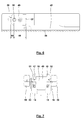
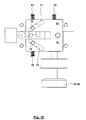
- Fig. 1 shows exemplary and highly schematic of a solar connector 1.
- a seal 5 is arranged at a defined distance 3 from a front side 4.
- the seal 5 adjacent end portion of the cable 2 is stripped and crimped over a crimping tool with a plug 6.
- a connector housing 9 is moved, pushed or pressed by means of a solar connector assembly tool 8.
- a locking lug 10 behind the plug 6.
- the seal 5 is compressed radially between the outer surface of the cable 2 and the stepped inner surface 99 of the plug housing 9. This is to ensure a seal of the solar connector 1.
- via the compression of the seal 5 between the connector housing 9 and cable 2 is a recording of acting on the cable 2 during operation forces, whereby a "strain relief" can be done.
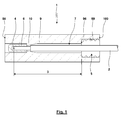
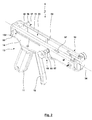
- Fig. 2 shows the solar connector mounting tool 8 in a three-dimensional view.
- the solar connector mounting tool 8 has a "gun-shaped” design, wherein the solid “pistol grip” forms a housing-fixed lever 11, while the “trigger” is extended according to the length of the hand lever 11 and forms a pivotable hand lever 12.
- the run indicates a mounting axis 34 with a mounting direction 97 along which takes place in the solar connector assembly tool 8 moving, here pushing the plug housing 9 on the assembly 7.
- a housing 13 of the solar connector mounting tool 8 is formed with two half shells 14, 15, which form a dividing plane in a longitudinal center plane of the solar connector mounting tool 8.
- the solar connector mounting tool 8 has a drive mechanism 16, a moving unit 17, a checking device 18, and a fixing unit 19.
- the drive mechanism 16 is formed with the pivoted hand lever 12, which is rigidly connected within the housing 13 with a drive crank 20 ( Fig. 5 ).
- the hand lever 12 in the connected to the drive crank 20 end portion has a flattening in the region of which the hand lever 12 via a connecting pin 21 and a pivot pin 22 fixedly connected to two on both sides of the flattened plate-shaped drive crank plates 23, 24 connected , which together form the drive crank 20.
- the pivot pin 22 is pivotally mounted in the projecting from the drive crank plates 23, 24 end portions in the half-shells 14, 15 of the housing 13, so that the hand lever 12 with the drive crank 20 is pivotable about a predetermined by the pivot pin 22 pivot axis.
- the other spring base of the tension spring 26 is supported under prestress on a bolt 27 which is mounted endwise in the half shells 14, 15 of the housing 13.
- the spring bias of the tension spring 26 causes the hand lever 12 in Fig. 5 is applied with a torque counterclockwise, so that the hand lever 12 is acted upon by the hand lever 11 away.
- Hand lever 12 and drive crank 20 together form a lever, wherein hand lever 12 on the one hand and drive crank 20 are arranged on opposite sides of the pivot pin 22 formed with the pivot bearing.
- the drive crank 20 is held by the drive crank plates 23, 24, a pivot pin 28.
- a toothed plunger 29 is pivotally mounted between the drive crank plates 23, 24.
- the pivot axis of the toothed ram 29 is in this case oriented parallel to the predetermined by the pivot pin 22 pivot axis.
- the toothed ram 29 extends from the pivot pin 28 at the front, wherein the toothed ram 29 is acted upon by a spring element, here a via a housing-fixed pin 30 supported spiral leg spring 31, upwards.
- the toothed ram 29 has a toothed segment 32 in its end region facing away from the pivot pin 28.
- the toothed segment 32 interacts with a guide slide 33, which is displaceably guided in the direction of the mounting axis 34 with respect to the housing 13.
- the guide carriage 33 has on its underside a rack-like toothing 34, whose longitudinal extension in the direction of the mounting axis 34 corresponds at least to the desired assembly stroke of the solar connector assembly tool 8.
- the toothed segment 32 engages as a result of the loading by the spiral leg spring 31 in the toothing 35 a.
- the tooth contours of the toothed segment 32 and the toothing 35 are selected such that the guide carriage 33 manually in Fig.
- a pawl 37 via a pivot pin 38 is pivotally mounted relative to the housing 13.
- spring element here a spiral leg spring 39
- the pawl 37 with a toothed segment 40 of the same against the teeth 35 is applied.
- the toothed ram 29 and the pawl 37 are in this case offset in the direction of the mounting axis 34, but arranged with a certain overlap, while these are offset transversely to the mounting axis and transversely to the longitudinal center plane.
- the pawl 37 has an actuating pin 31, which passes through a guide slot 42 in the half shell 15 of the housing 13.
- the pawl 37 in the in Fig. 5 shown upper end position, in which caused by the spiral leg spring 39, the toothed segment 40 can enter into operative connection with the toothing 35 in order to secure the once reached axial position of the guide carriage 33. If, however, the actuating pin 41 is pressed manually outside the housing 13 down, the toothed segment 40 of the pawl 37 is excluded Engagement with the toothing 35, whereby the securing effect of Zwangsgesperres 36 can be canceled.
- the toothed plunger 49 is also driven downwards by the pawl 37 when the actuating pin 41 is manually actuated downwards, so that the toothed segment 32 of the toothed plunger 29 is also disengaged from the toothing 35.
- a spring 44 which pulls the guide carriage 33 against the mounting direction 97 to the rear, when both the toothed segment 32 and the toothed segment 40 is out of engagement with the toothing 35.
- the movement unit 17, which can also be designed as a holding, drive and / or guide unit, is formed with the guide carriage 33.
- the guide carriage 33 has in the mounting direction in the rear end region 97 has a U-shaped cross section, the base leg of a base plate 45 and the side legs of two parallel side plates 46, 47 are formed. While the side plate 46 is formed continuously over the entire length of the guide carriage 33, the side plate 47 ends approximately centrally, so that in the front end region of the guide carriage 33 has only an L-shaped cross section.
- the base plate 45 is equipped with a suitable contour 48, which is adapted to the outer contour of the plug housing 9.
- Fig. 6 shows a side view of the guide slide 33 shown here transparent with a holding body 49 disposed therein.
- the holding body 49 is rotatably connected to a transversely extending to the mounting axis 34 pivot pin 50 which by aligned through holes 51, 52 of the side plates 46, 47 and parallel to the mounting axis 34 oriented guide slots 53, 54 passes through the housing 13 and in the end regions rotatably connected with wing nuts 55, 56 is connected ( Fig. 7 ).
- Fig. 2 and 14 is the holding body 49 in a first operating position, in which the holding body 49 can hold a plug housing 9 with a first geometry.
- This holding can consist in that the plug housing 9 rests against an end face 57 of the holding body 49 and is supported.
- the end face 57 is suitably contoured to allow the holding of the plug housing 9, has a recess into which the plug housing 9 enters or the holding body 49 is "encompassed" by a sleeve-like plug housing 9.
- the pivot pin 50 is eccentrically arranged in the holding body 49 such that the distance 59 of the end face 57 of the pivot axis of the pivot pin 50 is greater than the distance 60 of the pivot axis of the pivot pin 50 from the end face 58.
- the difference of the distances 59, 60 correspond to the length of the extension 61, by which the male connector housing 9 is longer than the female connector housing 9. It is possible that the holding body 49 with its underside in the two operating positions on the base plate 45th is supported. Under certain circumstances, an additional backup of the operating positions of the holding body 49, for example by a locking or locking device. For this purpose, transversely to the mounting axis 34 in the holding body 49 (or in a side plate 46, 47), a locking element elastically supported, which engages in the operating positions in a corresponding recess of the side plate 46, 47 (or the holding body 49).
- the change in the operating position of the holding body 49 can be caused by a rotation of the wing nuts 55, 56.
- the pivot pin 50 has, together with the holding body 49 and the guide carriage 33 in the direction of the mounting axis 34 and by the guide slots 53, 54 predetermined (further) degree of freedom.
- a manual loading of the wing nuts 55, 56 in mounting direction 97 causes pushed as a unit of the guide carriage 33 with holding body 49 and the supported on the holding body 49 plug housing 9 in the mounting direction 97 to the front be, with the toothed segments 40, 32 move ratchet-like along the teeth 35.
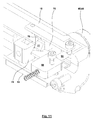
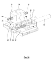
- the fixing unit 19 is arranged in the front end region of the "run" of the solar connector assembly tool 8 and serves to position and hold the pre-assembled assembly 7.
- the fixing unit 19 is shown in different disassembly stages in particular in the Fig. 10 to 13 and 15, 16 and 20.
- the fixing unit 19 is formed with a drive body 62, which is here plate-shaped, has only one degree of freedom parallel to the mounting axis 34 and is guided relative to a guide carriage 93. Via a spring element 63 of the guide carriage 93 is biased against the assembly direction 97 to the rear under bias against a stop 64 of the housing 13.
- An actuator 65 here an operating wheel 66, transverse to the mounting axis 34 by applying an actuating force 67 in the direction of in Fig. 15 shown dissolved position to be actuated while the actuator 65 due to a spring without applying the actuating force 67 in the in Fig. 16 shown fixing position returns. With the movement of the actuating member 65 between the two mentioned positions, a groove body 68 is moved.
- the groove body 68 has on its underside pointing to the drive body 62 a slot or a long groove 69, whose or its longitudinal axis both relative to the mounting axis 34 and with respect to the actuation direction of the actuating member 65 is inclined.
- a sliding block or pin 70 engages a sliding block or pin 70, which extends from the drive body 62 upwards.
- a drive connection stage 71 is formed, by means of which, in view of the inclined orientation of the slot 69, a movement of the groove body 68, caused by the actuation of the actuator 65, is converted transversely to the mounting axis 34 in a movement of the drive body 62 coaxial to the mounting axis 34.
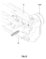
- the drive body 62 has two V-shaped elongated holes 72, 73, which extend symmetrically on both sides of the mounting axis 34.
- the longitudinal axis of the elongated holes 72, 73 is both inclined relative to the mounting axis 34 and to the actuating direction of the actuator. Transverse to the mounting axis 34 are compared to the guide carriage two jaws 74, 75 out, which in particular in Fig. 11 can be seen.
- the jaws 74, 75 each have V-shaped clamping surfaces 76, 77 which together in cross-section parallelogram are arranged and a clamped in the jaws 74, 75 cable 2 clamp over the circumference, wherein the size of the parallelogram is dependent on the distance of the jaws 74, 75 from each other and thus of the diameter of the cable 2.
- the jaws 74, 75 are in Direction of the mounting axis 34 offset from each other, so that they are guided past each other laterally.
- the jaws 74, 75 each have on the bottom downwardly extending sliding blocks or pins 78, 79, with which they engage in the slots 72, 73 of the drive body 62.
- a further drive connection stage 80 is formed, which is a movement of the drive body 62 in the direction of the mounting axis 34, which is caused by an actuation of the actuator 65 using the drive connection stage 71 converts into a movement of the jaws 74, 75 transversely to the mounting axis 34, namely a movement of the jaws 74, 75 toward or away from each other.
- the jaws 74, 75 acted upon by springs 81, 82 which are supported on the housing 13 to each other.
- opening of the clamping jaws 74, 75 can take place such that a cable 2 is inserted into the fixing unit 19 from above.
- the elimination of the actuating force 67 causes the operating position of the fixing unit 19 of Fig. 15 in Fig. 16 changed, which as a result of the springs 81, 82 and possibly another spring 83 which acts on the groove body 68 or the actuator 65, the jaws 74, 75 are closed until the clamping surfaces 76, 77 to the outer surface of the cable 2 to the plant come and pinch this and fix it.
- the axial position of the assembly formed with the cable 2 7 is selected such that the seal 5 is in a predetermined axial position, which in particular rests against an end face of the guide carriage 93.
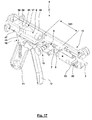
- This inserted into the solar connector assembly tool 8 state of the assembly 7 is, for example, in Fig. 17 shown. In this position, the plug housing 9 on the one hand and the assembly 7 on the other hand are arranged coaxially with each other.
- the checking device 18 is arranged between the moving unit 17 and the fixing unit 19.
- the test device 18 is formed with a test specimen 84.
- the test body 84 has an actuating button 85 and a hereby rigidly connected actuating plunger 86, which extends through a leading bore 87 of the half-shell 14 of the housing 13 therethrough.
- a spring 88 which extends for the illustrated embodiment, outside of the housing 13 around the actuating plunger 86 around and caught and biased between the housing 13 and the operating knob is, the test piece 84 is applied without manual application of the actuating knob 85 to the outside. Manually, the test piece 84 can be pressed transversely to the mounting axis 34 inwardly into the housing 13.
- the test body 84 is not rotated about its actuating axis.
- the test device 18 is in the in Fig. 8 and Fig. 17 shown rest position.
- the actuating tappet 86 is formed in a rough approximation in the form of a horizontal U, so that it forms an open-edged recess 89, which is bounded by webs 90, 91.
- the plug 6 is formed out of round, namely flattened, in particular as a result of the crimping process in the axial region where it interacts with the test body 84.
- the plug 6 can enter the open-edged recess 89 as a result of its flattening, thus achieving a test position. If, however, the plug 6 is rotated relative to this correct orientation about the mounting axis 34, the plug 6 can not enter the open-edged recess 89, but rather collides with the recess 89 limiting webs 90, 91 of the actuating plunger 86.
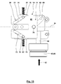
- the described fixing unit 19 is fixed in the direction of the mounting axis 34.
- the fixing unit is formed with a guide carriage 93, on which in the direction of the mounting axis 34 slidably the drive body 62 is mounted and the other explained components of the fixing unit are supported.
- the guide carriage 93 is pressed counter to the mounting direction 97 of the movement unit 17 by the prestressed spring element 63 against the stop 64. If a force is applied to the guide carriage 93 in the mounting direction 97, which is greater than the biasing force of the spring element 63, the guide carriage 93 can detach from the stop 64, so that the guide carriage 93 (and herewith the other components the fixing unit 19) in the mounting direction 97 can move.
- a coupling rod 94 passes between the actuator 65 and groove member 68 through a slot 95 of the half shell 15 of the housing 13, wherein the length of the elongated hole 95 at least the permissible movement of the guide carriage 93 corresponds.
- the mounting movement may consist in that the plug housing 9 held by the movement unit 17 is pushed onto the assembly 7 held in the fixing unit 19. It is within the scope of the invention but quite possible that a fixing unit holds the connector housing 9, while a moving unit einschiebt the assembly held thereon 7 in the connector housing 9. Accordingly possible is the use of a drive mechanism by means of which a mounting or retraction takes place. For example, for a pulling movement instead of a pressure-loaded actuating tappet 86, an actuating tension element with associated drive mechanism can be used. Preferably, however, no pulling takes place through the plug housing 9, as is the case for the initially described prior art.
- the wing nuts 55, 56 represent an embodiment for the formation of an actuating member 102, by means of which both the idle stroke of the guide carriage 33 can be generated as well as the rotation of the holding body 49th
- a spring element is formed with a plurality of partial spring elements.
- the biasing force for the guide carriage 93 of the fixing unit 19 for the illustrated embodiments is generated with a plurality of parallel-acting part spring elements.
Abstract
Description
Die Erfindung betrifft ein Solarverbinder-Montagewerkzeug, welches zur Montage eines Solarverbinders verwendet wird. Bei einem derartigen Solarverbinder wird ein Steckergehäuse relativ zu einer Baugruppe bewegt und hierdurch auf die Baugruppe aufgeschoben und mittels dieses Aufschiebens aufgepresst. Die Baugruppe ist hierbei mit einem Kabel und einem mit dem Kabel verpressten Stecker sowie in einigen Fällen mit einer auf dem Kabel angeordneten Dichtung gebildet.The invention relates to a solar connector mounting tool, which is used for mounting a solar connector. In such a solar connector, a connector housing is moved relative to an assembly and thereby pushed onto the assembly and pressed by means of this pushing. The assembly is formed here with a cable and a connector pressed with the cable and in some cases with a seal arranged on the cable.
Bekannt ist, beispielsweise von der
Der Erfindung liegt die Aufgabe zugrunde, ein Solarverbinder-Montagewerkzeug vorzuschlagen, mittels dessen eine zuverlässige bestimmungsgemäße Montage einer Baugruppe, die mit einem Kabel und einem mit dem Kabel verpressten Stecker (sowie in einigen Fällen auch mit einer auf dem Kabel angeordneten Dichtung) gebildet ist, mit einem Steckergehäuse gewährleistet ist.The invention has for its object to provide a solar connector mounting tool by means of which a reliable intended assembly of an assembly formed with a cable and a cable pressed connector with the cable (and in some cases with a seal arranged on the cable), is guaranteed with a connector housing.
Die Aufgabe der Erfindung wird erfindungsgemäß mit den Merkmalen des unabhängigen Patentanspruchs gelöst. Weitere bevorzugte erfindungsgemäße Ausgestaltungen sind den abhängigen Patentansprüchen zu entnehmen.The object of the invention is achieved with the features of the independent claim. Further preferred embodiments according to the invention can be found in the dependent claims.
Die Erfindung betrifft ein Solarverbinder-Montagewerkzeug, mittels dessen ein Steckergehäuse auf eine Baugruppe geschoben oder gezogen werden kann. Diese Baugruppe ist mit einem Kabel und einem mit dem Kabel verpressten Stecker gebildet. Unter Umständen verfügt die Baugruppe auch über eine auf dem Kabel angeordneten Dichtung. Das erfindungsgemäße Solarverbinder-Montagewerkzeug umfasst hierbei Ausführungsformen, bei welcher eine schiebende oder ziehende Relativbewegung zwischen Steckergehäuse und Baugruppe erfolgt, so dass hierbei eine relative Bewegung des Steckergehäuses und/oder der Baugruppe erfolgen kann.The invention relates to a solar connector assembly tool by means of which a connector housing can be pushed or pulled onto an assembly. This assembly is formed with a cable and a connector pressed with the cable. Under certain circumstances, the assembly also has a seal arranged on the cable. The solar connector mounting tool according to the invention in this case comprises embodiments in which a sliding or pulling relative movement between the plug housing and assembly takes place, so that in this case a relative movement of the plug housing and / or the module can be done.
Der erfindungsgemäßen Ausgestaltung liegt die Erkenntnis zugrunde, dass für die bekannten Solarverbinder-Montagewerkzeuge das Einhalten einer vorgegebenen Orientierung oder eines Drehwinkels des Steckers in dem Steckergehäuse davon abhängig ist, wie sorgfältig der Benutzer des Solarverbinder-Montagewerkzeugs die mit dem Stecker gebildete Baugruppe in das Solarverbinder-Montagewerkzeug einlegt. Selbst wenn noch das Einlegen der Montagegruppe sehr sorgfältig mit der richtigen Orientierung erfolgt, kann es vor der endgültigen Montage des Steckergehäuses mit der Baugruppe zu unerwünschten Veränderungen der Orientierung des Steckers kommen, was der Benutzer unter Umständen im inneren des Solarverbinder-Montagewerkzeugs nicht richtig sehen kann. Da das Steckergehäuse in einer definierten, über die Geometrie des Steckergehäuses vorgegebenen Orientierung in ein Gegen-Steckergehäuse eingesteckt wird, kann es daher dazu kommen, dass der in dem Steckergehäuse mit nicht richtiger Orientierung montierte Stecker nicht richtig den in dem Gegen-Steckergehäuse angeordneten Gegen-Stecker kontaktiert oder sogar mit diesem kollidiert, womit das Einstecken des Steckergehäuses in das Gegen-Steckergehäuse unmöglich sein kann.The embodiment according to the invention is based on the finding that, for the known solar connector assembly tools, compliance with a predetermined orientation or angle of rotation of the plug in the plug housing depends on how carefully the user of the solar connector mounting tool inserts the assembly formed in the solar connector. Mounting tool inserts. Even if the mounting of the assembly group is done very carefully with the correct orientation, it may lead to undesirable changes in the orientation of the connector before the final assembly of the connector housing with the assembly, which the user may not see properly inside the solar connector assembly tool , Since the plug housing is plugged into a counter plug housing in a defined orientation predetermined by the geometry of the plug housing, it may therefore happen that the plug mounted in the plug housing with incorrect orientation does not properly cover the counter plug housing arranged in the opposite plug housing. Plug contacted or even collided with this, whereby the plugging of the plug housing in the mating connector housing may be impossible.
Erfindungsgemäß wird vor diesem Hintergrund vorgeschlagen, dass das Solarverbinder-Montagewerkzeug eine Prüfeinrichtung besitzt, über die das Einlegen der Baugruppe, insbesondere des Steckers, mit der richtigen Orientierung in das Solarverbinder-Montagewerkzeug geprüft werden kann. Dies kann unmittelbar mit oder nach dem Einlegen der Baugruppe erfolgen. Ebenfalls möglich ist, dass die Prüfung unmittelbar vor dem Bewegen des Steckergehäuses auf die Baugruppe zu zwecks nochmaliger Prüfung unmittelbar vor der Montage erfolgt. Erfindungsgemäß kann somit die Montagezuverlässigkeit hinsichtlich der Orientierung der Baugruppe in dem Steckergehäuse erhöht werden.According to the invention it is proposed against this background that the solar connector mounting tool has a test device, via which the insertion of the module, in particular of the plug, can be checked with the correct orientation in the solar connector mounting tool. This can be done immediately with or after inserting the module. It is also possible that the test takes place immediately before moving the connector housing on the assembly for the purpose of re-testing immediately before mounting. Thus, according to the invention, the mounting reliability with respect to the orientation of the package in the plug housing can be increased.
In weiterer Ausgestaltung der Erfindung besitzt die Prüfeinrichtung eine Prüfstellung und eine Ruhestellung. In einer Ruhestellung tritt die Prüfeinrichtung beispielsweise nicht in Wechselwirkung mit der Baugruppe. In der Ruhestellung kann auch das Einlegen der Baugruppe in das Solarverbinder-Montagewerkzeug ermöglicht oder vereinfacht sein. Ebenfalls möglich ist, dass die Ruhestellung eingenommen wird während des Bewegens, insbesondere des Auf- oder Einschiebens oder Ziehens des Steckergehäuses relativ zu der Baugruppe, womit dieser Montagevorgang durch die Prüfeinrichtung nicht behindert wird. Hingegen erfolgt in der Prüfstellung bzw. auf dem Weg von der Ruhestellung zu der Prüfstellung die eigentliche Prüfung, ob die Baugruppe mit der richtigen Orientierung in das Solarverbinder-Montagewerkzeug eingelegt ist.In a further embodiment of the invention, the test device has a test position and a rest position. For example, in a rest position, the tester does not interact with the assembly. In the rest position, the insertion of the assembly in the solar connector assembly tool can be made possible or simplified. It is also possible that the rest position is taken during the movement, in particular the pushing or pushing or pulling of the plug housing relative to the assembly, whereby this assembly operation is not hindered by the testing device. On the other hand, in the test position or on the way from the rest position to the test position, the actual test is carried out as to whether the module is inserted with the correct orientation into the solar connector mounting tool.
Die Prüfeinrichtung kann beliebig ausgebildet sein und beliebige Freiheitsgrade besitzen, die die Prüfstellung und die Ruhestellung inkludieren können. Für eine besondere Ausgestaltung der Erfindung ist die Prüfeinrichtung durch Bewegung quer zur Montagerichtung von der Ruhestellung in die Prüfstellung (und umgekehrt) bewegbar. Somit kann die Prüfeinrichtung über kurze Wege von der Baugruppe weg und in Richtung dieser bewegt werden.The test device can be of any desired design and have any degrees of freedom that can include the test position and the rest position. For a particular embodiment of the invention, the test device by movement transversely to the mounting direction of the rest position in the test position (and vice versa) movable. Thus, the tester can be moved over short distances away from the module and in the direction of this.
Die Prüfeinrichtung kann auf beliebige Weise funktionieren. Um lediglich ein nicht beschränkendes Beispiel zu nennen, kann mittels der Prüfeinrichtung eine optische Prüfung erfolgen, beispielsweise indem geprüft wird, ob eine Kante des Steckers mit einer Referenzkante oder Markierung eines Gehäuses des Solarverbinder-Montagewerkzeugs fluchtet. Für eine besondere Ausgestaltung der Erfindung erfolgt aber eine formschlüssige Prüfung: Mit dieser Ausgestaltung ist die Bewegung der Prüfeinrichtung von der Ruhestellung in die Prüfstellung blockiert, wenn die Prüfeinrichtung nicht mit der richtigen Orientierung in das Solarverbinder-Montagewerkzeug eingelegt ist, während die Bewegung der Prüfeinrichtung nicht blockiert ist, wenn die Baugruppe mit der richtigen Orientierung in das Solarverbinder-Montagewerkzeug eingelegt ist. Somit kann der Benutzer probeweise die Prüfeinrichtung betätigen und prüfen, ob eine Blockade erfolgt, womit ein Hinweis darauf gegeben ist, ob die richtige Orientierung gewährleistet ist.The test device can work in any way. By way of example only, a non-limiting example may be made by means of the test device, for example, by checking that an edge of the plug is aligned with a reference edge or mark of a housing of the solar connector mounting tool. For a particular embodiment of the invention, however, a positive test is carried out: With this embodiment, the movement of the test device is blocked from the rest position to the test position, if the test device is not inserted with the correct orientation in the solar connector assembly tool, while the movement of the test device is not is blocked when the module is inserted in the solar connector mounting tool with the correct orientation. Thus, the user can tentatively operate the testing device and check whether a blockage occurs, which is an indication of whether the correct orientation is guaranteed.
Möglich ist, dass die Prüfeinrichtung mehrere unter Umständen multistabile Stellungen wie die Prüfstellung und die Ruhestellung aufweist. In einer besonderen Ausgestaltung der Erfindung ist die Prüfeinrichtung über eine Feder in die Ruhestellung beaufschlagt, so dass diese automatisiert eingenommen ist. Wird die Prüfeinrichtung dann manuell von dem Benutzer beaufschlagt, überwindet der Benutzer durch Betätigungskräfte die Feder, womit die Prüfeinrichtung von der Ruhestellung in die Prüfstellung überführt werden kann.It is possible that the testing device has several possibly multi-stable positions such as the test position and the rest position. In a particular embodiment of the invention, the test device is acted upon by a spring in the rest position, so that it is taken automatically. If the test device is then manually applied by the user, overcomes the user by actuating forces the spring, with which the test device can be transferred from the rest position to the test position.
In der Prüfeinrichtung kann ein beliebiger Prüfkörper Einsatz finden, welcher beispielsweise eine geeignete Anlagefläche besitzt, die auf einer Referenzfläche des Steckers zur Anlage kommen kann, wenn dieser in der richtigen Orientierung in das Solarverbinder-Montagewerkzeug eingelegt ist, während die Bewegung des Prüfkörpers für andere Orientierungen blockiert ist. Für eine besondere Ausgestaltung der Erfindung ist aber die Prüfeinrichtung mit einem Prüfkörper ausgebildet, welcher eine randoffene Ausnehmung besitzt. Durch diese randoffene Ausnehmung erstreckt sich in der Prüfstellung der Stecker. Anders gesagt kann der Prüfkörper mit der randoffenen Ausnehmung bei der Bewegung von der Ruhestellung in die Prüfstellung mit der randoffenen Ausnehmung, beispielsweise gabelförmig, über den Stecker geschoben werden, wenn der Stecker in der richtigen Orientierung in das Solarverbinder-Montagewerkzeug eingelegt ist.In the test device, any test body can be used, which has, for example, a suitable contact surface, which can come to rest on a reference surface of the plug, if this is inserted in the correct orientation in the solar connector mounting tool, while the movement of the test specimen for other orientations is blocked. For a particular embodiment of the invention, however, the test device is formed with a test specimen having an open-edged recess. Through this open-edged recess extending in the test position of the plug. In other words, the test body can be pushed with the open-edged recess in the movement from the rest position to the test position with the open-edged recess, for example fork-shaped, over the plug when the plug is inserted in the correct orientation in the solar connector mounting tool.
Vorteilhafte Weiterbildungen der Erfindung ergeben sich aus den Patentansprüchen, der Beschreibung und den Zeichnungen. Die in der Beschreibung genannten Vorteile von Merkmalen und von Kombinationen mehrerer Merkmale sind lediglich beispielhaft und können alternativ oder kumulativ zur Wirkung kommen, ohne dass die Vorteile zwingend von erfindungsgemäßen Ausführungsformen erzielt werden müssen. Ohne dass hierdurch der Gegenstand der beigefügten Patentansprüche verändert wird, gilt hinsichtlich des Offenbarungsgehalts der ursprünglichen Anmeldungsunterlagen und des Patents Folgendes: weitere Merkmale sind den Zeichnungen - insbesondere den dargestellten Geometrien und den relativen Abmessungen mehrerer Bauteile zueinander sowie deren relativer Anordnung und Wirkverbindung - zu entnehmen. Die Kombination von Merkmalen unterschiedlicher Ausführungsformen der Erfindung oder von Merkmalen unterschiedlicher Patentansprüche ist ebenfalls abweichend von den gewählten Rückbeziehungen der Patentansprüche möglich und wird hiermit angeregt. Dies betrifft auch solche Merkmale, die in separaten Zeichnungen dargestellt sind oder bei deren Beschreibung genannt werden. Diese Merkmale können auch mit Merkmalen unterschiedlicher Patentansprüche kombiniert werden. Ebenso können in den Patentansprüchen aufgeführte Merkmale für weitere Ausführungsformen der Erfindung entfallen.Advantageous developments of the invention will become apparent from the claims, the description and the drawings. The advantages of features and of combinations of several features mentioned in the description are merely exemplary and can take effect alternatively or cumulatively, without the advantages having to be achieved by embodiments according to the invention. Without thereby altering the subject matter of the appended claims, as regards the disclosure of the original application documents and the patent, further features can be found in the drawings, in particular the illustrated geometries and the relative dimensions of several components and their relative arrangement and operative connection. The combination of features of different embodiments of the invention or of features of different claims is also possible deviating from the chosen relationships of the claims and is hereby stimulated. This also applies to those features which are shown in separate drawings or are mentioned in their description. These features can also be combined with features of different claims. Likewise, in the claims listed features for further embodiments of the invention can be omitted.
Die in den Patentansprüchen und der Beschreibung genannten Merkmale sind bezüglich ihrer Anzahl so zu verstehen, dass genau diese Anzahl oder eine größere Anzahl als die genannte Anzahl vorhanden ist, ohne dass es einer expliziten Verwendung des Adverbs "mindestens" bedarf. Wenn also beispielsweise von einem Element die Rede ist, ist dies so zu verstehen, dass genau ein Element, zwei Elemente oder mehr Elemente vorhanden sind. Wenn hingegen nur die genaue Anzahl eines Merkmals angegeben werden soll, findet das Adjektiv "genau" vor dem jeweiligen Merkmal Verwendung. Diese Merkmale können durch andere Merkmale ergänzt werden oder die einzigen Merkmale sein, aus denen das jeweilige Erzeugnis besteht.The features mentioned in the patent claims and the description are to be understood in terms of their number that exactly this number or a greater number than the said number is present, without requiring an explicit use of the adverb "at least". For example, when talking about an element, it should be understood that there is exactly one element, two elements or more elements. If, on the other hand, only the exact number of a feature is to be specified, the adjective "exactly" before the respective feature is used. These features may be supplemented by other features or be the only characteristics that make up the product in question.
Die in den Patentansprüchen enthaltenen Bezugszeichen stellen keine Beschränkung des Umfangs der durch die Patentansprüche geschützten Gegenstände dar. Sie dienen lediglich dem Zweck, die Patentansprüche leichter verständlich zu machen.The reference numerals contained in the claims do not limit the scope of the objects protected by the claims. They are for the sole purpose of making the claims easier to understand.
Im Folgenden wird die Erfindung anhand in den Figuren dargestellter bevorzugter Ausführungsbeispiele weiter erläutert und beschrieben.
- Fig. 1
- zeigt grob schematisiert einen Solarverbinder, der mit einem Kabel, einem Stecker, einer Dichtung und einem Steckergehäuse gebildet ist.
- Fig. 2
- zeigt in einer räumlichen Darstellung ein Solarverbinder-Montagewerkzeug ohne eingelegte Bauelemente eines Solarverbinders.
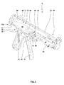
- Fig. 3
- zeigt das Solarverbinder-Montagewerkzeug gemäß
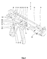
Fig. 2 in räumlicher Darstellung in teildemontiertem Zustand. - Fig. 4
- zeigt das Solarverbinder-Montagewerkzeug gemäß
Fig. 2 in räumlicher Darstellung in weiter teildemontiertem Zustand. - Fig. 5
- zeigt in einem Längsmittelschnitt das Solarverbinder-Montagewerkzeug gemäß
Fig. 1-4 . - Fig. 6
- zeigt in einer Seitenansicht Bestandteile einer in dem Solarverbinder-Montagewerkzeug eingesetzten Bewegungseinheit.
- Fig. 7
- zeigt in einem Teilquerschnitt VII-VII das Solarverbinder-Montagewerkzeug gemäß
Fig. 1-5 . - Fig. 8
- zeigt in einem Querschnitt VIII-VIII das Solarverbinder-Montagewerkzeug gemäß
Fig. 1-5 . - Fig. 9
- zeigt in einem Querschnitt IX-IX das Solarverbinder-Montagewerkzeug gemäß
Fig. 1-5 . - Fig. 10
- zeigt im Detail eine Fixiereinheit des Solarverbinder-Montagewerkzeugs gemäß
Fig. 1-5 in räumlicher Darstellung mit teildemontiertem Gehäuse. - Fig. 11
- zeigt die Fixiereinheit gemäß
Fig. 10 in räumlicher Darstellung in weiter demontiertem Zustand. - Fig. 12
- zeigt die Fixiereinheit gemäß
Fig. 11 in räumlicher Darstellung in weiter demontiertem Zustand. - Fig. 13
- zeigt die Fixiereinheit gemäß
Fig. 12 in räumlicher Darstellung in weiter demontiertem Zustand. - Fig. 14
- zeigt das Solarverbinder-Montagewerkzeug in teildemontiertem Zustand in einer räumlichen Ansicht, wobei in dieses eine Baugruppe mit einem Kabel, einer Dichtung und einem Stecker eingelegt ist.
- Fig. 15
- zeigt Bauelemente einer Fixiereinheit eines Solarverbinder-Montagewerkzeugs von unten, wobei die Fixiereinheit manuell in die gelösten Stellung betätigt ist.
- Fig. 16
- zeigt Bauelemente der Fixiereinheit gemäß
Fig. 15 , wobei sich die Fixiereinheit in der Fixierstellung befindet. - Fig. 17
- zeigt das Solarverbinder-Montagewerkzeug in teildemontiertem Zustand in räumlicher Darstellung, wobei in dieses eine Baugruppe sowie ein Steckergehäuse eingelegt sind und noch keine Montage des Steckergehäuses mit der Baugruppe erfolgt ist.
- Fig. 18
- zeigt eine
Fig. 17 entsprechende Darstellung, hier aber nach Beendigung der Montage des Steckergehäuses mit der Baugruppe durch Aufschieben des Steckergehäuses auf die Baugruppe. - Fig. 19
- zeigt das Solarverbinder-Montagewerkzeug gemäß
Fig. 17 und 18 mit Überschreiten der Vorspannkraft des Federelements, über welches die Fixiereinheit abgestützt ist. - Fig. 20
- zeigt Bauelemente der Fixiereinheit in einer räumlichen Ansicht.
- Fig. 1
- roughly shows a solar connector, which is formed with a cable, a plug, a seal and a connector housing.
- Fig. 2
- shows a spatial representation of a solar connector assembly tool without inserted components of a solar connector.
- Fig. 3
- shows the solar connector mounting tool according to
Fig. 2 in spatial representation in partially dismantled state. - Fig. 4
- shows the solar connector mounting tool according to
Fig. 2 in a spatial representation in a further partially dismantled state. - Fig. 5
- shows in a longitudinal center section according to the solar connector assembly tool
Fig. 1-4 , - Fig. 6
- shows in a side view components of a movement unit used in the solar connector assembly tool.
- Fig. 7
- shows in a partial cross section VII-VII according to the solar connector assembly tool
Fig. 1-5 , - Fig. 8
- shows in a cross section VIII-VIII according to the solar connector assembly tool
Fig. 1-5 , - Fig. 9
- shows in a cross section IX-IX according to the solar connector assembly tool
Fig. 1-5 , - Fig. 10
- shows in detail a fixing unit of the solar connector mounting tool according to
Fig. 1-5 in spatial representation with partially dismantled housing. - Fig. 11
- shows the fixing unit according to
Fig. 10 in a spatial representation in a further disassembled state. - Fig. 12
- shows the fixing unit according to
Fig. 11 in a spatial representation in a further disassembled state. - Fig. 13
- shows the fixing unit according to
Fig. 12 in a spatial representation in a further disassembled state. - Fig. 14
- shows the solar connector assembly tool in partially dismantled state in a three-dimensional view, in which an assembly with a cable, a gasket and a plug is inserted.
- Fig. 15
- shows components of a fixing unit of a solar connector assembly tool from below, wherein the fixing unit is manually operated in the released position.
- Fig. 16
- shows components of the fixing unit according to
Fig. 15 , wherein the fixing unit is in the fixing position. - Fig. 17
- shows the solar connector assembly tool in partially dismantled state in a spatial representation, in which an assembly and a connector housing are inserted and yet no assembly of the connector housing has been done with the assembly.
- Fig. 18
- shows one
Fig. 17 corresponding representation, but here after completion of the assembly of the connector housing with the module by pushing the connector housing on the module. - Fig. 19
- shows the solar connector mounting tool according to
Fig. 17 and18 with exceeding the biasing force of the spring element, via which the fixing unit is supported. - Fig. 20
- shows components of the fixing unit in a spatial view.
Das Solarverbinder-Montagewerkzeug 8 verfügt über einen Antriebsmechanismus 16, eine Bewegungseinheit 17, eine Prüfeinrichtung 18 und eine Fixiereinheit 19.The solar
Der Antriebsmechanismus 16 ist gebildet mit dem verschwenkten Handhebel 12, welcher innerhalb des Gehäuses 13 starr mit einer Antriebskurbel 20 verbunden ist (
Die Bewegungseinheit 17, welche auch als Halte-, Antriebs und/oder Führungseinheit ausgebildet sein kann, ist mit dem Führungsschlitten 33 gebildet. Der Führungsschlitten 33 besitzt in dem in Montagerichtung 97 rückwärtigen Endbereich einen U-förmigen Querschnitt, dessen Grundschenkel von einer Grundplatte 45 und dessen Seitenschenkel von zwei parallelen Seitenplatten 46, 47 ausgebildet sind. Während die Seitenplatte 46 über die gesamte Länge des Führungsschlittens 33 durchgehend ausgebildet ist, endet die Seitenplatte 47 ungefähr mittig, sodass im vorderen Endbereich der Führungsschlitten 33 lediglich einen L-förmigen Querschnitt besitzt. Die Grundplatte 45 ist mit einer geeigneten Konturierung 48 ausgestattet, welche an die Außenkontur des Steckergehäuses 9 angepasst ist.
Wie erläutert kann über eine Verdrehung der Flügelmuttern 55, 56 die Veränderung der Betriebsstellung des Haltekörpers 49 verursacht werden. Der Schwenkbolzen 50 besitzt gemeinsam mit dem Haltekörper 49 sowie dem Führungsschlitten 33 einen in Richtung der Montageachse 34 und durch die Führungsschlitze 53, 54 vorgegebenen (weiteren) Freiheitsgrad. Eine manuelle Beaufschlagung der Flügelmuttern 55, 56 in Montagerichtung 97 führt dazu, dass als eine Einheit der Führungsschlitten 33 mit Haltekörper 49 und dem an dem Haltekörper 49 abgestützten Steckergehäuse 9 in Montagerichtung 97 nach vorne geschoben werden, wobei sich die Zahnsegmente 40, 32 ratschenartig entlang der Verzahnung 35 bewegen.As explained, the change in the operating position of the holding
Die Fixiereinheit 19 ist im vorderen Endbereich des "Laufs" des Solarverbinder-Montagewerkzeugs 8 angeordnet und dient dem Positionieren und Halten der vormontierten Baugruppe 7. Die Fixiereinheit 19 ist in unterschiedlichen Demontagestufen insbesondere dargestellt in den
Die Prüfeinrichtung 18 ist zwischen der Bewegungseinheit 17 und der Fixiereinheit 19 angeordnet. Für das dargestellte Ausführungsbeispiel ist die Prüfeinrichtung 18 mit einem Prüfkörper 84 gebildet. Der Prüfkörper 84 besitzt einen Betätigungsknopf 85 und einen hiermit starr verbundenen Betätigungsstößel 86, welcher sich durch eine führende Bohrung 87 der Halbschale 14 des Gehäuses 13 hindurch erstreckt. Mittels einer Feder 88, welche sich für das dargestellte Ausführungsbeispiel außerhalb des Gehäuses 13 um den Betätigungsstößel 86 herum erstreckt und zwischen Gehäuse 13 und Betätigungsknopf gefangen und vorgespannt ist, wird der Prüfkörper 84 ohne manuelle Beaufschlagung des Betätigungsknopfes 85 nach außen beaufschlagt. Manuell kann der Prüfkörper 84 quer zur Montageachse 34 nach innen in das Gehäuse 13 gedrückt werden. Über entsprechende (nicht dargestellte) Führungselemente ist gewährleistet, dass der Prüfkörper 84 nicht um seine Betätigungsachse verdrehbar ist. Ohne manuelle Betätigung des Prüfkörpers 84 befindet sich die Prüfeinrichtung 18 in der in
Grundsätzlich möglich ist, dass die beschriebene Fixiereinheit 19 in Richtung der Montageachse 34 fixiert ist. Für das dargestellte Ausführungsbeispiel ist aber die Fixiereinheit mit einem Führungsschlitten 93 ausgebildet, an welchem in Richtung der Montageachse 34 verschieblich der Antriebskörper 62 gelagert ist sowie die anderen erläuterten Bauelemente der Fixiereinheit abgestützt sind. Der Führungsschlitten 93 wird entgegen der Montagerichtung 97 der Bewegungseinheit 17 durch das vorgespannte Federelement 63 gegen den Anschlag 64 gepresst. Wird auf den Führungsschlitten 93 eine Kraft in Montagerichtung 97 aufgebracht, die größer ist als die Vorspannkraft des Federelements 63, kann sich der Führungsschlitten 93 von dem Anschlag 64 lösen, so dass sich der Führungsschlitten 93 (und hiermit die weiteren Bauelemente der Fixiereinheit 19) in Montagerichtung 97 bewegen können. Um diesen Freiheitsgrad des Führungsschlittens 93 mit den zugeordneten Bauelementen der Fixiereinheit 19 zu gewährleisten, tritt eine Koppelstange 94 zwischen Betätigungsorgan 65 und Nutkörper 68 durch ein Langloch 95 der Halbschale 15 des Gehäuses 13 hindurch, wobei die Länge des Langloches 95 zumindest der zulässigen Bewegung des Führungsschlittens 93 entspricht.In principle, it is possible that the described fixing
Die Funktion des Solarverbinder-Montagewerkzeugs 8 ist wie folgt:
- a) Zunächst wird das Betätigungsorgan 65 mit einer
Betätigungskraft 67 manuell betätigt, um dieKlemmbacken Montagewerkzeug 8die vormontierte Baugruppe 7 eingelegt. Hierbei erfolgt die axiale Ausrichtung der Baugruppe 7 derart, dass dieDichtung 5 mitder dem Stecker 6 abgewandten Stirnseite andem Führungsschlitten 93 anliegt. Durch Beseitigung der auf das Betätigungsorgan 65 wirkenden Betätigungskraft 67 wird ein Einklemmen und fixieren des Kabels durch dieKlemmbacken den Klemmflächen - b) Je nachdem, welcher Typ eines Steckergehäuses 9
mit der Baugruppe 7 montiert werden soll, wird durch Verdrehen einer Flügelmutter 55, 56der Haltekörper 49 in die richtige Betriebsstellung gebracht. Dannwird das Steckergehäuse 9 des der Betriebsstellung zugeordneten Typs von oben in das Solarverbinder-Montagewerkzeug 8 eingelegt,wobei die Stirnseite 98 desSteckergehäuses 9 zur Anlage andie wirksame Stirnseite Haltekörpers 49 kommt unddas Steckergehäuse 9 auf der Grundplatte 45 und der Konturierung 48 aufliegt. - c) Jetzt oder unter Umständen auch vor der Durchführung des Verfahrensschritts b) wird durch Betätigung der Prüfeinrichtung 18 überprüft, ob für die eingelegte Baugruppe 7
der Stecker 6 richtig orientiert ist, also die randoffene Ausnehmung 89über den Stecker 6 geschoben werden kann. Ist dies nicht der Fall, muss dieBaugruppe 7 gemäß a) nochmals neu in das Solarverbinder-Montagewerkzeug 8 eingelegt werden. - d) Zu diesem Zeitpunkt
hat eine Stirnseite 100 desSteckergehäuses 9von der Dichtung 5 noch einen Abstand, welcher einen Leerhub 101 erfordert, der ausgeführt werden muss, bevor die eigentliche Montage erfolgt.Müsste dieser Leerhub 101 bereits durch Betätigung des Antriebsmechanismus 16 mit der sukzessiven wiederholten Verschwenkung des Handhebels 12 überwunden werden, wären hierzu mehrere Betätigungsstufen des Handhebels 12 erforderlich, was einen unnötigen Aufwand darstellen würde. Um diesen Aufwand zu vermeiden, kann durch axiale Betätigung der Flügelmuttern 55, 56entlang der Führungsschlitze Montagerichtung 97 eine Verschiebung des Führungsschlittens 33mit dem Haltekörper 46 und darauf gehaltenen Steckergehäuse 9 erfolgen, bis dieInnenfläche 99 desSteckergehäuses 9 mit der Mantelfläche der Dichtung 5 in Wirkverbindung tritt. Zu diesem Zeitpunkt ist bereits derStecker 6 mit dem der Dichtung 5 vorgelagerten Endbereich des Kabels 2 in das Innere des Steckergehäuses 9 eingetreten. Spürt der Benutzer, dass sich zu diesem Zeitpunkt ein erhöhter Widerstand gegen die Bewegung ergibt, erkennt der Benutzer, dass der Leerhub beendet ist. - e) Nun beginnt der eigentliche Montage- oder Presshub, für welchen der Benutzer
den Handhebel 12 in Richtung des festen Handhebels 11 verschwenkt, womit der Zahnstößel 29 um einen Teilmontagehub nach vorne bewegt wird, womit auch eine Bewegung der Verzahnung 35 und damit auch des Führungsschlittens 33mit Haltekörper 49 und Steckergehäuse 9 einhergeht. Nach diesem Teilmontagehub und Schließung der Handhebel 11 , 12 schwenkt dieFeder 26 nach Beseitigung der Handkraftden Handhebel 12 wieder weg vondem festen Handhebel 11, was zur Folge hat, dass der Zahnstößel 29 zurückbewegt wird,womit das Zahnsegment 32 ratschenartig entlang der Verzahnung 35 bewegt wird. Die Position des Führungsschlittens 33 wird hierbei überdas Zwangsgesperre 36 gesichert, so dass sich der Führungsschlitten 33 trotz der Beaufschlagung durch dieFeder 44 nicht zurückbewegen kann.
Nun kann der Benutzer durch erneutes und wiederholtes Verschwenken des Handhebels 12 inRichtung des Handhebels 11 weitere Teilmontagehübe erzeugen, womit letztendlichdas Steckergehäuse 9 immer weiter auf dieBaugruppe 7 aufgeschoben wird. Während des Montagehubs ist insbesondere dieDichtung 5 und/oder das Steckergehäuse 9 stirnseitig an der Fixiereinheit 19 abgestützt. Diese Abstützung nimmt die von der Rastnase 10 sowie demReibkontakt zwischen Dchtung 5 und Steckergehäuse 9 hervorgerufen Montagekraft auf. - f) Während des Aufschiebens des Steckergehäuses 9 auf die
Baugruppe 7 ist die ausgeübte Montagekraft zunächst kleiner als die Vorspannung, mittels welcherdas Federelement 63den Führungsschlitten 93 gegenden Anschlag 64 presst. Hierbei hängt die Montagekraft maßgeblich von der Reibkraft zwischen Dichtung 5 und der Innenfläche 99 desSteckergehäuses 9 sowie der Wechselwirkung zwischen der Rastnase 10 und der Baugruppe 7 ab. Befindet sichhingegen das Steckergehäuse 9 in der fertig montierten Stellung gemäßFig. 1 , führt eine weitere Erhöhung der Montagekraft dazu, dass sich die eine Stirnseite der Dichtung 5 aneinem Absatz 96 desSteckergehäuses 9 zusätzlich abstützt, womit es zu einem weiteren Anstieg der Montagekraft kommt. Überschreitet diese Montagekraft die Vorspannung, mittels welcherdas Federelement 63den Führungsschlitten 93 gegenden Anschlag 64 presst, beginnt der Führungsschlitten 93 sich zu bewegen, womit dem Benutzer sichtbar gemacht wird, dass die Montage und das Aufschieben beendet sind und eine definierte Montagekraft überschritten ist. Ein Vergleich derFig. 18 und 19 zeigt die Bewegung des Führungsschlittens 93 mit Überschreiten der Vorspannkraft, vgl. den sich verringernden Spalt 103. - g) Nun kann der Betätigungsbolzen 41 in
dem Führungsschlitz 42 manuell nach unten gedrückt werden, womit dieZahnsegmente mit Haltekörper 49 über dieFeder 44 zurückgezogen werden, währenddas Steckergehäuse 9 in seiner montierten Position auf der Baugruppe 7 verbleibt. - h) Anschließend wird die
Fixiereinheit 19 in ihre gelöste Stellung überführt, so dass die Klemmkräfte zwischenden Klemmbacken und dem Kabel 2 beseitigt werden. Wird nun andem Kabel 2 inMontagerichtung 97 mit einer Prüfkraft gezogen, stützt sich eine Stirnseite der Dichtung 5 oder dieStirnseite 100 desSteckergehäuses 9 andem Führungsschlitten 93 bzw. anderen Bauelementen der Fixiereinheit 19 ab. Überschreitet die Prüfkraft die Vorspannung, mit welcherdas Federelement 63den Führungsschlitten 93 gegenden Anschlag 64 vorspannt, kommt es zu einer für den Benutzer spürbaren und/oder sichtbaren Bewegung desFührungsschlittens 93. Somit kann eine Prüfung des fertig montierten Solarverbinders 1 mit einer durch die Vorspannung des Federelements 63 vorgegebenen definierten Prüfkraft noch in dem Solarverbinder-Montagewerkzeug 8 erfolgen. - i) Für geöffnete Fixiereinheit 19 kann
nun der Solarverbinder 1 aus dem Solarverbinder-Montagewerkzeug 8 entnommen werden.
- a) First, the actuator 65 is manually operated with an actuating
force 67 to open thejaws jaws preassembled module 7 is inserted from above into the solarconnector assembly tool 8. In this case, the axial alignment of theassembly 7 takes place in such a way that theseal 5 bears against theguide carriage 93 with the end face facing away from theplug 6. By eliminating the operatingforce 67 acting on the actuating member 65, pinching and fixing of the cable by the clampingjaws - b) Depending on which type of
plug housing 9 is to be mounted with theassembly 7, the holdingbody 49 is brought into the correct operating position by turning awing nut plug housing 9 of the operating position associated type is inserted from above into the solarconnector mounting tool 8, wherein theend face 98 of theplug housing 9 to bear against theeffective end face body 49 and theconnector housing 9 on thebase plate 45 and theContour 48 rests. - c) Now or under certain circumstances before the implementation of the method step b) is checked by pressing the
test device 18, if theplug 6 is correctly oriented for the insertedmodule 7, so the open-edgedrecess 89 can be pushed over theplug 6. If this is not the case, theassembly 7 according to a) must be re-inserted into the solarconnector assembly tool 8. - d) At this time, an
end face 100 of theplug housing 9 of theseal 5 still has a distance which requires aLeerhub 101, which must be performed before the actual assembly takes place. Would this Leerhub 101 already by Operation of thedrive mechanism 16 are overcome with the successive repeated pivoting of thehand lever 12, this would require a plurality of actuation levels of thehand lever 12, which would be an unnecessary expense. To avoid this expense, by axial actuation of thewing nuts guide slots assembly direction 97, a displacement of theguide carriage 33 with the holdingbody 46 and held thereonconnector housing 9, until theinner surface 99 of theplug housing 9 with the lateral surface theseal 5 comes into operative connection. At this time, theplug 6 has already entered the inside of theplug housing 9 with the end region of thecable 2 upstream of theseal 5. If the user senses that there is increased resistance to the movement at this time, the user recognizes that the idle stroke has ended. - e) Now begins the actual assembly or pressing stroke, for which the user pivots the
hand lever 12 in the direction of thefixed hand lever 11, whereby thetoothed ram 29 is moved to a Teilmontagehub forward, bringing a movement of theteeth 35 and thus also theguide carriage 33 with holdingbody 49 andconnector housing 9 is accompanied. After this Teilmontagehub and closing thehand lever spring 26 after eliminating the manual force thehand lever 12 away from thefixed hand lever 11, with the result that thetoothed plunger 29 is moved back, bringing thetoothed segment 32 ratchet-like along the teeth 35th is moved. The position of theguide carriage 33 is secured in this case via theZwangsgesperre 36, so that theguide carriage 33, despite the action of thespring 44 can not move back.
Now, the user can generate by further and repeated pivoting of thehand lever 12 in the direction of thehand lever 11 more Teilmontagehübe, which ultimately theconnector housing 9 is pushed further and further onto theassembly 7. During the assembly stroke, in particular theseal 5 and / or theplug housing 9 is supported on the front side of the fixingunit 19. This support takes on the lockinglug 10 and the frictional contact betweenDchtung 5 andconnector housing 9 caused assembly force. - f) During the sliding of the
plug housing 9 on theassembly 7, the applied assembly force is initially smaller than the bias voltage by means of which thespring element 63 presses theguide carriage 93 against thestop 64. Here, the mounting force depends largely on the frictional force between theseal 5 and theinner surface 99 of theplug housing 9 and the interaction between the lockinglug 10 and theassembly 7. If, however, theplug housing 9 is in the fully assembled position according toFig. 1 , A further increase in the mounting force causes the one end face of theseal 5 is additionally supported on ashoulder 96 of theplug housing 9, resulting in a further increase in the assembly force. Exceeds this assembly force the bias, by means of which thespring element 63 presses theguide carriage 93 against thestop 64, theguide carriage 93 begins to move, making the user is visible that the assembly and the postponement are completed and a defined assembly force is exceeded. A comparison ofFig. 18 and19 shows the movement of theguide carriage 93 with exceeding the biasing force, see. the decreasinggap 103. - g) Now, the
actuating pin 41 can be manually pressed down in theguide slot 42, whereby thetoothed segments teeth 35 and theguide carriage 33 are retracted with holdingbody 49 via thespring 44, while theconnector housing 9 in his mounted position on theassembly 7 remains. - h) Subsequently, the fixing
unit 19 is transferred to its released position, so that the clamping forces between thejaws cable 2 are eliminated. If a test force is now drawn on thecable 2 in the mountingdirection 97, an end face of theseal 5 or theend face 100 of theplug housing 9 is supported on theguide carriage 93 or other components of the fixingunit 19. Exceeds the test load, the bias with which thespring element 63 biases theguide carriage 93 against thestop 64, there is a noticeable to the user and / or visible movement of theguide carriage 93. Thus, a test of the assembledsolar connector 1 with a through the Preload thespring element 63 predetermined defined test force still done in the solarconnector assembly tool 8. - i) For open fixing
unit 19, thesolar connector 1 can now be removed from the solarconnector assembly tool 8.
Wie in den dargestellten Ausführungsbeispielen kann die Montagebewegung darin bestehen, dass das von der Bewegungseinheit 17 gehaltene Steckergehäuse 9 auf die in der Fixiereinheit 19 gehaltene Baugruppe 7 aufgeschoben wird. Es ist im Rahmen der Erfindung aber durchaus auch möglich, dass eine Fixiereinheit das Steckergehäuse 9 hält, während eine Bewegungseinheit die daran gehaltene Baugruppe 7 in das Steckergehäuse 9 einschiebt. Entsprechend möglich ist auch die Nutzung eines Antriebsmechanismus, mittels welchem ein Auf- oder Einziehen erfolgt. Beispielsweise kann für eine ziehende Bewegung anstelle eines auf Druck beanspruchten Betätigungsstößels 86 ein betätigendes Zugelement mit zugeordnetem Antriebsmechanismus Einsatz finden. Vorzugsweise erfolgt aber kein Ziehen durch das Steckergehäuse 9 hindurch, wie dieses für den eingangs erläuterten Stand der Technik der Fall ist.As in the illustrated embodiments, the mounting movement may consist in that the
Die Flügelmuttern 55, 56 stellen ein Ausführungsbeispiel für die Ausbildung eines Betätigungsorgans 102 dar, mittels dessen sowohl der Leerhub des Führungsschlittens 33 erzeugt werden kann als auch die Verdrehung des Haltekörpers 49.The
Durchaus möglich ist, dass ein Federelement mit mehreren Teilfederelementen ausgebildet ist. So wird beispielsweise die Vorspannkraft für den Führungsschlitten 93 der Fixiereinheit 19 für die dargestellten Ausführungsbeispiele mit mehreren parallel wirkenden Teilfederelementen erzeugt.It is entirely possible that a spring element is formed with a plurality of partial spring elements. For example, the biasing force for the
- 11
- Solarverbindersolar connector
- 22
- Kabelelectric wire
- 33
- Abstanddistance
- 44
- Stirnseitefront
- 55
- Dichtungpoetry
- 66
- Steckerplug
- 77
- Baugruppemodule
- 88th
- Solarverbinder-MontagewerkzeugSolar connector assembly tool
- 99
- Steckergehäuseplug housing
- 1010
- Rastnaselocking lug
- 1111
- Handhebelhand lever
- 1212
- Handhebelhand lever
- 1313
- Gehäusecasing
- 1414
- Halbschalehalf shell
- 1515
- Halbschalehalf shell
- 1616
- Antriebsmechanismusdrive mechanism
- 1717
- Bewegungseinheitmoving unit
- 1818
- Prüfeinrichtungtest equipment
- 1919
- Fixiereinheitfuser
- 2020
- Antriebskurbeldrive crank
- 2121
- Verbindungsbolzenconnecting bolts
- 2222
- Schwenkbolzenpivot pin
- 2323
- AntriebskurbelplatteDrive crank
- 2424
- AntriebskurbelplatteDrive crank
- 2525
- Fortsatzextension
- 2626
- Zugfedermainspring
- 2727
- Bolzenbolt
- 2828
- Schwenkbolzenpivot pin
- 2929
- Zahnstößeltooth ram
- 3030
- Bolzenbolt
- 3131
- SpiralschenkelfederSpiral torsion spring
- 3232
- Zahnsegmenttoothed segment
- 3333
- Führungsschlittenguide carriage
- 3434
- Montageachsemounting axis
- 3535
- Verzahnunggearing
- 3636
- ZwangsgesperreZwangsgesperre
- 3737
- Sperrklinkepawl
- 3838
- Schwenkbolzenpivot pin
- 3939
- SpiralschenkelfederSpiral torsion spring
- 4040
- Zahnsegmenttoothed segment
- 4141
- Betätigungsbolzenactuating pin
- 4242
- Führungsschlitzguide slot
- 4343
- Mitnehmerbolzendriving pins
- 4444
- Federfeather
- 4545
- Grundplattebaseplate
- 4646
- Seitenplatteside plate
- 4747
- Seitenplatteside plate
- 4848
- Konturierungcontouring
- 4949
- Haltekörperholding body
- 5050
- Schwenkbolzenpivot pin
- 5151
- DurchgangsbohrungThrough Hole
- 5252
- DurchgangsbohrungThrough Hole
- 5353
- Führungsschlitzguide slot
- 5454
- Führungsschlitzguide slot
- 5555
- Flügelmutterbutterfly nut
- 5656
- Flügelmutterbutterfly nut
- 5757
- Stirnseitefront
- 5858
- Stirnseitefront
- 5959
- Abstanddistance
- 6060
- Abstanddistance
- 6161
- Fortsatzextension
- 6262
- Antriebskörperdrive body
- 6363
- Federelementspring element
- 6464
- Anschlagattack
- 6565
- Betätigungsorganactuator
- 6666
- Betätigungsradoperating wheel
- 6767
- Betätigungskraftoperating force
- 6868
- Nutkörpergroove body
- 6969
- Langloch oder LangnutLong hole or long groove
- 7070
- Stiftpen
- 7171
- AntriebsverbindungsstufeDrive connection stage
- 7272
- LanglochLong hole
- 7373
- LanglochLong hole
- 7474
- Klemmbackejaw
- 7575
- Klemmbackejaw
- 7676
- Klemmflächeclamping surface
- 7777
- Klemmflächeclamping surface
- 7878
- Stiftpen
- 7979
- Stiftpen
- 8080
- AntriebsverbindungsstufeDrive connection stage
- 8181
- Federfeather
- 8282
- Federfeather
- 8383
- Federfeather
- 8484
- Prüfkörperspecimen
- 8585
- Betätigungsknopfactuating button
- 8686
- Betätigungsstößelactuating ram
- 8787
- Bohrungdrilling
- 8888
- Federfeather
- 8989
- Ausnehmungrecess
- 9090
- Stegweb
- 9191
- Stegweb
- 9292
- Absatzparagraph
- 9393
- Führungsschlittenguide carriage
- 9494
- Koppelstangecoupling rod
- 9595
- LanglochLong hole
- 9696
- Absatzparagraph
- 9797
- Montagerichtungmounting direction
- 9898
- Stirnseitefront
- 9999
- Innenflächepalm
- 100100
- Stirnseitefront
- 101101
- Leerhubidle stroke
- 102102
- Betätigungsorganactuator
- 103103
- Spaltgap
Claims (6)
Priority Applications (1)
| Application Number | Priority Date | Filing Date | Title |
|---|---|---|---|
| EP12170865.5A EP2672583A1 (en) | 2012-06-05 | 2012-06-05 | Solar connector assembly tool |
Applications Claiming Priority (1)
| Application Number | Priority Date | Filing Date | Title |
|---|---|---|---|
| EP12170865.5A EP2672583A1 (en) | 2012-06-05 | 2012-06-05 | Solar connector assembly tool |
Publications (1)
| Publication Number | Publication Date |
|---|---|
| EP2672583A1 true EP2672583A1 (en) | 2013-12-11 |
Family
ID=46318907
Family Applications (1)
| Application Number | Title | Priority Date | Filing Date |
|---|---|---|---|
| EP12170865.5A Withdrawn EP2672583A1 (en) | 2012-06-05 | 2012-06-05 | Solar connector assembly tool |
Country Status (1)
| Country | Link |
|---|---|
| EP (1) | EP2672583A1 (en) |
Cited By (2)
| Publication number | Priority date | Publication date | Assignee | Title |
|---|---|---|---|---|
| EP2995424A1 (en) | 2014-09-11 | 2016-03-16 | Wezag GmbH Werkzeugfabrik | Pliers |
| DE202014011110U1 (en) | 2014-09-11 | 2017-11-29 | Wezag Gmbh Werkzeugfabrik | hand tool |
Citations (1)
| Publication number | Priority date | Publication date | Assignee | Title |
|---|---|---|---|---|
| US5038461A (en) * | 1989-08-31 | 1991-08-13 | Societe Nationale Industrielle Et Aerospatiale | Device and system for crimping connecting elements on electric conductors |
-
2012
- 2012-06-05 EP EP12170865.5A patent/EP2672583A1/en not_active Withdrawn
Patent Citations (1)
| Publication number | Priority date | Publication date | Assignee | Title |
|---|---|---|---|---|
| US5038461A (en) * | 1989-08-31 | 1991-08-13 | Societe Nationale Industrielle Et Aerospatiale | Device and system for crimping connecting elements on electric conductors |
Non-Patent Citations (1)
| Title |
|---|
| "Betriebsanleitung Solarkit Universal MC", 1 August 2011 (2011-08-01), XP055039947, Retrieved from the Internet <URL:http://www.tritec-energy.com/images/content/D_174_Rennsteig_UniversalKit_INST_des.pdf> [retrieved on 20121003] * |
Cited By (3)
| Publication number | Priority date | Publication date | Assignee | Title |
|---|---|---|---|---|
| EP2995424A1 (en) | 2014-09-11 | 2016-03-16 | Wezag GmbH Werkzeugfabrik | Pliers |
| DE202014011110U1 (en) | 2014-09-11 | 2017-11-29 | Wezag Gmbh Werkzeugfabrik | hand tool |
| US9864948B2 (en) | 2014-09-11 | 2018-01-09 | Wezag Gmbh Werkzeugfabrik | Hand pliers |
Similar Documents
| Publication | Publication Date | Title |
|---|---|---|
| EP2082837B1 (en) | Crimping pliers | |
| EP3012923B1 (en) | Jointing clamp | |
| EP2562891B1 (en) | Crimping tool | |
| EP3614507B1 (en) | Pressing or crimping tool | |
| AT514078B1 (en) | bending tool | |
| DE102010021704B4 (en) | Lock cap for a buckle | |
| EP2596878A2 (en) | Multiple-use tool for a punching device | |
| DE7837471U1 (en) | PLIERS LIKE TOOL | |
| DE102018121971A1 (en) | Press tool | |
| EP2078591B1 (en) | Pressing tool | |
| DE1102846B (en) | Hand tools for pressing tubular connectors onto electrical conductors | |
| EP2115829B1 (en) | Positioning device for crimping tools | |
| EP1888280A1 (en) | Connection between two tool parts | |
| EP3553899A1 (en) | Crimping tool | |
| EP2672585B1 (en) | Solar connector assembly tool | |
| DE102009058981A1 (en) | Device for setting fasteners | |
| EP3834989B1 (en) | Hand-held clamping tool and method for assembling the same | |
| EP2672583A1 (en) | Solar connector assembly tool | |
| DE102007005176A1 (en) | Positioning device for crimping tools | |
| EP2672582A1 (en) | Solar connector assembly tool | |
| EP2233086A1 (en) | Tick removing device | |
| DE102004018429B4 (en) | Device for applying an axial compressive force | |
| EP2512705A1 (en) | Device for setting fastening elements | |
| DE202019001563U1 (en) | Press tool for a fitting with press tab | |
| DE102016116878A1 (en) | Drive unit for a crimping tool and crimping tool |
Legal Events
| Date | Code | Title | Description |
|---|---|---|---|
| STAA | Information on the status of an ep patent application or granted ep patent |
Free format text: STATUS: REQUEST FOR EXAMINATION WAS MADE |
|
| PUAI | Public reference made under article 153(3) epc to a published international application that has entered the european phase |
Free format text: ORIGINAL CODE: 0009012 |
|
| 17P | Request for examination filed |
Effective date: 20130307 |
|
| AK | Designated contracting states |
Kind code of ref document: A1 Designated state(s): AL AT BE BG CH CY CZ DE DK EE ES FI FR GB GR HR HU IE IS IT LI LT LU LV MC MK MT NL NO PL PT RO RS SE SI SK SM TR |
|
| AX | Request for extension of the european patent |
Extension state: BA ME |
|
| RBV | Designated contracting states (corrected) |
Designated state(s): AL AT BE BG CH CY CZ DE DK EE ES FI FR GB GR HR HU IE IS IT LI LT LU LV MC MK MT NL NO PL PT RO RS SE SI SK SM TR |
|
| STAA | Information on the status of an ep patent application or granted ep patent |
Free format text: STATUS: THE APPLICATION IS DEEMED TO BE WITHDRAWN |
|
| 18D | Application deemed to be withdrawn |
Effective date: 20150106 |