EP2677152A1 - Variable thickness coatings for cylinder liners - Google Patents
Variable thickness coatings for cylinder liners Download PDFInfo
- Publication number
- EP2677152A1 EP2677152A1 EP13173010.3A EP13173010A EP2677152A1 EP 2677152 A1 EP2677152 A1 EP 2677152A1 EP 13173010 A EP13173010 A EP 13173010A EP 2677152 A1 EP2677152 A1 EP 2677152A1
- Authority
- EP
- European Patent Office
- Prior art keywords
- coating
- interior surface
- liner
- cylinder liner
- internal combustion
- Prior art date
- Legal status (The legal status is an assumption and is not a legal conclusion. Google has not performed a legal analysis and makes no representation as to the accuracy of the status listed.)
- Granted
Links
Images


Classifications
-
- F—MECHANICAL ENGINEERING; LIGHTING; HEATING; WEAPONS; BLASTING
- F02—COMBUSTION ENGINES; HOT-GAS OR COMBUSTION-PRODUCT ENGINE PLANTS
- F02F—CYLINDERS, PISTONS OR CASINGS, FOR COMBUSTION ENGINES; ARRANGEMENTS OF SEALINGS IN COMBUSTION ENGINES
- F02F1/00—Cylinders; Cylinder heads
- F02F1/004—Cylinder liners
-
- F—MECHANICAL ENGINEERING; LIGHTING; HEATING; WEAPONS; BLASTING
- F02—COMBUSTION ENGINES; HOT-GAS OR COMBUSTION-PRODUCT ENGINE PLANTS
- F02F—CYLINDERS, PISTONS OR CASINGS, FOR COMBUSTION ENGINES; ARRANGEMENTS OF SEALINGS IN COMBUSTION ENGINES
- F02F1/00—Cylinders; Cylinder heads
- F02F1/02—Cylinders; Cylinder heads having cooling means
- F02F1/10—Cylinders; Cylinder heads having cooling means for liquid cooling
- F02F1/16—Cylinder liners of wet type
-
- C—CHEMISTRY; METALLURGY
- C23—COATING METALLIC MATERIAL; COATING MATERIAL WITH METALLIC MATERIAL; CHEMICAL SURFACE TREATMENT; DIFFUSION TREATMENT OF METALLIC MATERIAL; COATING BY VACUUM EVAPORATION, BY SPUTTERING, BY ION IMPLANTATION OR BY CHEMICAL VAPOUR DEPOSITION, IN GENERAL; INHIBITING CORROSION OF METALLIC MATERIAL OR INCRUSTATION IN GENERAL
- C23C—COATING METALLIC MATERIAL; COATING MATERIAL WITH METALLIC MATERIAL; SURFACE TREATMENT OF METALLIC MATERIAL BY DIFFUSION INTO THE SURFACE, BY CHEMICAL CONVERSION OR SUBSTITUTION; COATING BY VACUUM EVAPORATION, BY SPUTTERING, BY ION IMPLANTATION OR BY CHEMICAL VAPOUR DEPOSITION, IN GENERAL
- C23C4/00—Coating by spraying the coating material in the molten state, e.g. by flame, plasma or electric discharge
-
- F—MECHANICAL ENGINEERING; LIGHTING; HEATING; WEAPONS; BLASTING
- F02—COMBUSTION ENGINES; HOT-GAS OR COMBUSTION-PRODUCT ENGINE PLANTS
- F02F—CYLINDERS, PISTONS OR CASINGS, FOR COMBUSTION ENGINES; ARRANGEMENTS OF SEALINGS IN COMBUSTION ENGINES
- F02F1/00—Cylinders; Cylinder heads
- F02F1/02—Cylinders; Cylinder heads having cooling means
- F02F1/04—Cylinders; Cylinder heads having cooling means for air cooling
- F02F1/06—Shape or arrangement of cooling fins; Finned cylinders
- F02F1/08—Shape or arrangement of cooling fins; Finned cylinders running-liner and cooling-part of cylinder being different parts or of different material
-
- F—MECHANICAL ENGINEERING; LIGHTING; HEATING; WEAPONS; BLASTING
- F16—ENGINEERING ELEMENTS AND UNITS; GENERAL MEASURES FOR PRODUCING AND MAINTAINING EFFECTIVE FUNCTIONING OF MACHINES OR INSTALLATIONS; THERMAL INSULATION IN GENERAL
- F16J—PISTONS; CYLINDERS; SEALINGS
- F16J10/00—Engine or like cylinders; Features of hollow, e.g. cylindrical, bodies in general
- F16J10/02—Cylinders designed to receive moving pistons or plungers
- F16J10/04—Running faces; Liners
-
- F—MECHANICAL ENGINEERING; LIGHTING; HEATING; WEAPONS; BLASTING
- F05—INDEXING SCHEMES RELATING TO ENGINES OR PUMPS IN VARIOUS SUBCLASSES OF CLASSES F01-F04
- F05C—INDEXING SCHEME RELATING TO MATERIALS, MATERIAL PROPERTIES OR MATERIAL CHARACTERISTICS FOR MACHINES, ENGINES OR PUMPS OTHER THAN NON-POSITIVE-DISPLACEMENT MACHINES OR ENGINES
- F05C2253/00—Other material characteristics; Treatment of material
- F05C2253/12—Coating
Definitions
- the subject matter disclosed herein in general relates to cylinder liners for internal combustion engines, and more specifically to variable thickness coatings for such cylinder liners.
- a typical internal combustion engines includes one or more pistons, a cylinder block and one or more cylinder liners.
- the cylinder liner or sleeve is a cylindrical part that is fitted into cylinder block to form a cylinder.
- the cylinder liner is a critical component of the engine.
- the cylinder liner functions as a sliding surface for the piston while retaining the lubricant. It is desirable for cylinder liners to have low friction and high anti-galling properties. Galling is a form of adhesive wear surface damage arising between sliding solids resulting in microscopic, usually localized roughening in the creation of surface distortions.
- the cylinder liner is under high temperature and high pressure with the piston and piston rings sliding at high speeds. Consequently, it is desirable lower friction coefficient for cylinder liners to have significant heat and wear resistant properties.
- Coatings have been developed to provide the cylinder liners with the desirable lower friction coefficients and heat and wear resistant properties.
- a number of technologies exist for applying the coating and a variety of coating materials may be used.
- the coating technologies that may be used are plasma spraying, high velocity oxygen fuel spraying, laser coating and chemical vapor deposition, and galvanic coating, among others.
- Materials used for coatings may include ceramics, composites of ceramics and metals (cermet), metal alloys, metal compounds (e.g. titanium oxides), among others.
- the materials used for coating of cylinder liners are expensive and add considerably to the manufacturing costs of the engines.
- the invention relates to a cylinder liner for an internal combustion engine including a liner body; the liner body defining a longitudinal axis and having a first end and a second end, a middle portion; and an interior surface; and a coating on the interior surface that varies in thickness along the longitudinal axis.
- the invention in another embodiment, relates to an internal combustion engine assembly including a piston, a liner having an interior surface and a lubricant.
- the internal combustion engine also includes a coating on the interior surface of the liner with a thinner in a region of the liner where the lubricant provides at least partial hydrodynamic lubrication.
- the invention in another embodiment, relates to a method of coating a cylinder liner for an internal combustion engine.
- the method includes coating a first interior surface of the liner with a first layer of predetermined thickness; coating a second interior surface with a second layer of predetermined thickness; and leaving a middle interior surface uncoated.
- the method includes coating middle section with a third layer thinner than the first layer and the second layer.
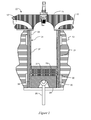
- FIG. 1 Illustrated in Figure 1 is a representative example of an embodiment of an internal combustion engine assembly 11.
- Internal combustion engine assembly 11 may include a cylinder block 13 having a cylinder head 15 which may also have an intake port 17 and an exhaust port 19.
- Disposed in the cylinder block 13 is a cylinder liner 21 and a piston 23.
- the cylinder liner 21 may be a separate component from the cylinder block 13 that is installed into the block 13.
- the cylinder liner 21 may be an integral portion of the block 13 and only describes the portion of the 13 block in which the piston 23 is disposed.
- Piston 23 may be coupled to a connecting rod 25 and may also include compression rings 27 and 29 and an oil control ring 30 disposed on the periphery of the piston 23.
- the cylinder liner 21 may include a coating 31 applied to a liner body XX. As shown in the embodiment illustrated by Figure 1 the coating 31 may have a variable thickness, with a thicker coating at the top dead center (TDC coating 33) and the bottom dead center (BDC coating 35). The coating at midstroke 37 may be thinner than the TDC coating 33 and BDC coating 35. In some embodiments there may be no coating in some or all of the midstroke portion 37.
- the coating 31 is applied to the interior surface 39 of the cylinder liner 21.
- Figure 1 illustrates the piston at the bottom dead center
- Figure 2 illustrates the piston 23 at the midstroke.
- the cylinder liner 21 is bored or honed in order to create a constant inner bore diameter (or radius) along the cylinder liner 21 and/or coating 31.
- the cylinder liner 21 is bored or honed but leaves a non-constant inner bore diameter along the cylinder liner 21 and/or coating 31.
- the cylinder liner 21 and/or coating 31 is not bored or honed after the coating 31 is applied.
- the engine assembly may be provided with a lubricant (not shown) that serves to reduce friction between the piston 23 and the cylinder liner 21 or coating 31.
- Friction is influenced by the type of surface. Friction in lubricated surfaces may be categorized as boundary friction (in regions with substantially no hydrodynamic lubrication), hydrodynamic friction (in regions with hydrodynamic lubrication), and mixed friction (in regions with at least partial hydrodynamic lubrication). Boundary friction relates to friction between surfaces that are completely dry and have only asperity contact between the surfaces. Hydrodynamic friction relates to friction between surfaces are completely separated by a lubricant with no asperity contact. Mixed friction occurs when boundary friction combines with hydrodynamic friction. Hydrodynamic friction is associated with hydrodynamic lubrication and boundary friction is associated with boundary conditions for the lubrication.
- Lubrication transitions from hydrodynamic to boundary conditions Hydrodynamic lubrication is promoted near the midstroke where the sliding velocity of the piston is high. At and near the top dead center and bottom dead center of the piston stroke, were sliding velocity as mobile lubrication transitions from hydrodynamic to boundary conditions. With boundary lubrication, the oil film breaks down leading to asperity contact and wear. The wear conditions are the most severe at the top dead center (TDC) because there is less oil available, the pressures are higher, and the viscosity is lower due to higher temperature. The least wear occurs at the piston midstroke. Consequently, more coating is desirable at the top dead center and bottom dead center regions of the cylinder liner 21. The midstroke region requires less coating. Significant reduction in the use of coating materials may be obtained by using a thinner coating in the mid-stroke region of the piston.
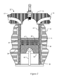
- FIG. 3 is a representative example of an embodiment of an internal combustion engine assembly 11 without a separate cylinder liner component (the liner in this embodiment is an integral portion of a cylinder block 13).
- the internal combustion engine assembly may include the cylinder block 13 having a cylinder head 15 which may also have an intake port 17 and an exhaust port 19. Disposed in the cylinder block 13 is a piston 23. Piston 23 may be coupled to a connecting rod 25 and may also include compression rings 27 and 29 and oil control ring 30 disposed on the periphery of the piston 23.
- the cylinder block 13 may include a coating 31. As shown in the embodiment illustrated by Figure 3 the coating 31 may have a variable thickness, with a thicker coating at the top dead center (TDC coating 33) and the bottom dead center (BDC coating 35). The coating at midstroke 37 may be thinner than the TDC coating 33 and BDC coating 35.
- the coating 31 is applied to the interior surface 39 of the cylinder block 13.
- Figures 4-9 illustrate various embodiments of coating applications that may be used to reduce the quantity of coating materials required for a cylinder liner 21.
- Figure 4 illustrates a partial cross-section along the longitudinal axes of a cylinder liner 21.
- the body of the cylinder liner 21 may be conceptually divided into three sections.
- the first end section 41 may correspond with the top dead center position for piston 23.
- the cylinder liner 21 may have a first interior surface 43 on which may be applied a first end section coating 44.
- a second end section 45 may correspond with the bottom dead center position for piston 23.
- the cylinder liner 21 may have a second interior surface 47 on which may be applied a second end section coating 48.
- Middle section 49 may be associated with a middle interior surface 51 on which a middle section coating 52 may be applied first end section coating 44, second end section coating 48, and middle section coating 52 may be the same material or may be comprised of different materials for the coating 31.
- first end section coating 44 and a second end section coating 48 are thicker than the middle section coating 52, and may taper linearly from a thick portion to a center portion.
- Figure 5 illustrates an embodiment where no middle section coating 52 is applied.
- Figure 6 illustrates an embodiment where only the first end section coating 44 is applied.
- FIG. 4-6 illustrates the thickness of the coating varies linearly along the longitudinal axis of the cylinder liner 21, it would be apparent to one of ordinary skill in the art that the cross-section of the coating may encompass curves other than a straight line.
- Figures 7-9 illustrate embodiments where the thickness of the coating 31 varies in a step function.
- the coating is applied at the first interior surface 43 and the second interior surface 47.
- the thickness of the first end section coating 44 and the second end section coating 48 do not vary along the longitudinal axis of the cylinder liner 21.
- Middle section coating 52 is thinner than the first end section coating 44 and the second end section coating 48.
- Figure 8 illustrates an embodiment where no coating is applied to the middle interior surface 51.
- Figure 9 illustrates an embodiment where only the first end section coating 44 is applied.
- coating of the cylinder liner 21 may be accomplished by any of the available methods of coating such as plasma spraying, high velocity oxygen fuel spraying, laser coating and chemical vapor deposition, and galvanic coating, among others.
- the coating process may include coating the first interior surface 43 with a first layer of predetermined thickness; coating the second interior surface 47 with a second layer of predetermined thickness; and leaving the middle interior surface 51 uncoated.
- coating may be accomplished by applying a coating on the middle interior surface 51 that is thinner than the first end section coating 44.
- the coating is only applied to the first interior surface 43.
- the term “near” means being located in the vicinity of an area, location, or object.
- the term “linearly” is used to describe a direction that is substantially a straight line, and it may encompass a direction with a minor degree of curvature.
- the "thickness” of coating is the dimension the coating along a radial direction.
- the term “thinner” relates to a thickness of the coating having a smaller dimension than a the dimension of a previously stated coating.
- predetermined thickness refers to a thickness established in advance to ensure protection of the cylinder liner from heat and contact damage.
Abstract
Description
- The subject matter disclosed herein in general relates to cylinder liners for internal combustion engines, and more specifically to variable thickness coatings for such cylinder liners.
- A typical internal combustion engines includes one or more pistons, a cylinder block and one or more cylinder liners. The cylinder liner or sleeve is a cylindrical part that is fitted into cylinder block to form a cylinder. The cylinder liner is a critical component of the engine. The cylinder liner functions as a sliding surface for the piston while retaining the lubricant. It is desirable for cylinder liners to have low friction and high anti-galling properties. Galling is a form of adhesive wear surface damage arising between sliding solids resulting in microscopic, usually localized roughening in the creation of surface distortions. The cylinder liner is under high temperature and high pressure with the piston and piston rings sliding at high speeds. Consequently, it is desirable lower friction coefficient for cylinder liners to have significant heat and wear resistant properties.
- Coatings have been developed to provide the cylinder liners with the desirable lower friction coefficients and heat and wear resistant properties. A number of technologies exist for applying the coating and a variety of coating materials may be used. Among the coating technologies that may be used are plasma spraying, high velocity oxygen fuel spraying, laser coating and chemical vapor deposition, and galvanic coating, among others. Materials used for coatings may include ceramics, composites of ceramics and metals (cermet), metal alloys, metal compounds (e.g. titanium oxides), among others. The materials used for coating of cylinder liners are expensive and add considerably to the manufacturing costs of the engines.
- In accordance with one exemplary non-limiting embodiment, the invention relates to a cylinder liner for an internal combustion engine including a liner body; the liner body defining a longitudinal axis and having a first end and a second end, a middle portion; and an interior surface; and a coating on the interior surface that varies in thickness along the longitudinal axis.
- In another embodiment, the invention relates to an internal combustion engine assembly including a piston, a liner having an interior surface and a lubricant. The internal combustion engine also includes a coating on the interior surface of the liner with a thinner in a region of the liner where the lubricant provides at least partial hydrodynamic lubrication.
- In another embodiment, the invention relates to a method of coating a cylinder liner for an internal combustion engine. The method includes coating a first interior surface of the liner with a first layer of predetermined thickness; coating a second interior surface with a second layer of predetermined thickness; and leaving a middle interior surface uncoated.
- In another embodiment, the method includes coating middle section with a third layer thinner than the first layer and the second layer.
- Other features and advantages of the present invention will be apparent from the following more detailed description of the preferred embodiment, taken in conjunction with the accompanying drawings which illustrate, by way of example, the principles of the invention.
-
-
Figure 1 is a cross section of a non-limiting piston assembly with a liner in accordance with one embodiment. -
Figure 2 is a cross section of a non-limiting piston assembly with a liner in accordance with one embodiment. -
Figure 3 is a cross section of a non-limiting piston assembly with a cylinder bore in accordance with one embodiment. -
Figure 4 is a non-limiting cross section of a liner in accordance with one embodiment. -
Figure 5 is a non-limiting cross section of a liner in accordance with one embodiment. -
Figure 6 is a non-limiting cross section of a liner in accordance with one embodiment. -
Figure 7 is a non-limiting cross section of a liner in accordance with one embodiment. -
Figure 8 is a non-limiting cross section of a liner in accordance with one embodiment. -
Figure 9 is a non-limiting cross section of a liner in accordance with one embodiment. - Illustrated in
Figure 1 is a representative example of an embodiment of an internalcombustion engine assembly 11. Internalcombustion engine assembly 11 may include acylinder block 13 having acylinder head 15 which may also have anintake port 17 and anexhaust port 19. Disposed in thecylinder block 13 is acylinder liner 21 and apiston 23. In some embodiments thecylinder liner 21 may be a separate component from thecylinder block 13 that is installed into theblock 13. In other embodiments thecylinder liner 21 may be an integral portion of theblock 13 and only describes the portion of the 13 block in which thepiston 23 is disposed. Piston 23 may be coupled to a connectingrod 25 and may also includecompression rings oil control ring 30 disposed on the periphery of thepiston 23. Thecylinder liner 21 may include acoating 31 applied to a liner body XX. As shown in the embodiment illustrated byFigure 1 thecoating 31 may have a variable thickness, with a thicker coating at the top dead center (TDC coating 33) and the bottom dead center (BDC coating 35). The coating atmidstroke 37 may be thinner than the TDC coating 33 andBDC coating 35. In some embodiments there may be no coating in some or all of themidstroke portion 37. Thecoating 31 is applied to theinterior surface 39 of thecylinder liner 21.Figure 1 illustrates the piston at the bottom dead center, andFigure 2 illustrates thepiston 23 at the midstroke. In some embodiments, after thecoating 31 is applied, thecylinder liner 21 is bored or honed in order to create a constant inner bore diameter (or radius) along thecylinder liner 21 and/or coating 31. In other embodiments, after thecoating 31 is applied, thecylinder liner 21 is bored or honed but leaves a non-constant inner bore diameter along thecylinder liner 21 and/or coating 31. In still other embodiments, thecylinder liner 21 and/orcoating 31 is not bored or honed after thecoating 31 is applied. The engine assembly may be provided with a lubricant (not shown) that serves to reduce friction between thepiston 23 and thecylinder liner 21 or coating 31. - In principle, the
coating 31 oncylinder liner 21 must provide low friction as well as wear resistant properties. Friction is influenced by the type of surface. Friction in lubricated surfaces may be categorized as boundary friction (in regions with substantially no hydrodynamic lubrication), hydrodynamic friction (in regions with hydrodynamic lubrication), and mixed friction (in regions with at least partial hydrodynamic lubrication). Boundary friction relates to friction between surfaces that are completely dry and have only asperity contact between the surfaces. Hydrodynamic friction relates to friction between surfaces are completely separated by a lubricant with no asperity contact. Mixed friction occurs when boundary friction combines with hydrodynamic friction. Hydrodynamic friction is associated with hydrodynamic lubrication and boundary friction is associated with boundary conditions for the lubrication. Lubrication transitions from hydrodynamic to boundary conditions. Hydrodynamic lubrication is promoted near the midstroke where the sliding velocity of the piston is high. At and near the top dead center and bottom dead center of the piston stroke, were sliding velocity as mobile lubrication transitions from hydrodynamic to boundary conditions. With boundary lubrication, the oil film breaks down leading to asperity contact and wear. The wear conditions are the most severe at the top dead center (TDC) because there is less oil available, the pressures are higher, and the viscosity is lower due to higher temperature. The least wear occurs at the piston midstroke. Consequently, more coating is desirable at the top dead center and bottom dead center regions of thecylinder liner 21. The midstroke region requires less coating. Significant reduction in the use of coating materials may be obtained by using a thinner coating in the mid-stroke region of the piston. -
Figure 3 is a representative example of an embodiment of an internalcombustion engine assembly 11 without a separate cylinder liner component (the liner in this embodiment is an integral portion of a cylinder block 13). The internal combustion engine assembly may include thecylinder block 13 having acylinder head 15 which may also have anintake port 17 and anexhaust port 19. Disposed in thecylinder block 13 is apiston 23.Piston 23 may be coupled to a connectingrod 25 and may also include compression rings 27 and 29 andoil control ring 30 disposed on the periphery of thepiston 23. Thecylinder block 13 may include acoating 31. As shown in the embodiment illustrated byFigure 3 thecoating 31 may have a variable thickness, with a thicker coating at the top dead center (TDC coating 33) and the bottom dead center (BDC coating 35). The coating atmidstroke 37 may be thinner than theTDC coating 33 andBDC coating 35. Thecoating 31 is applied to theinterior surface 39 of thecylinder block 13. -
Figures 4-9 illustrate various embodiments of coating applications that may be used to reduce the quantity of coating materials required for acylinder liner 21.Figure 4 illustrates a partial cross-section along the longitudinal axes of acylinder liner 21. As shown inFigure 4 the body of thecylinder liner 21 may be conceptually divided into three sections. Thefirst end section 41 may correspond with the top dead center position forpiston 23. Thecylinder liner 21 may have a firstinterior surface 43 on which may be applied a firstend section coating 44. Asecond end section 45 may correspond with the bottom dead center position forpiston 23. Thecylinder liner 21 may have a secondinterior surface 47 on which may be applied a secondend section coating 48.Middle section 49 may be associated with a middleinterior surface 51 on which amiddle section coating 52 may be applied firstend section coating 44, secondend section coating 48, andmiddle section coating 52 may be the same material or may be comprised of different materials for thecoating 31. In the embodiment illustrated inFigure 4 the firstend section coating 44 and a secondend section coating 48 are thicker than themiddle section coating 52, and may taper linearly from a thick portion to a center portion.Figure 5 illustrates an embodiment where nomiddle section coating 52 is applied.Figure 6 illustrates an embodiment where only the firstend section coating 44 is applied. Although in the embodiment inFigures 4-6 the thickness of the coating varies linearly along the longitudinal axis of thecylinder liner 21, it would be apparent to one of ordinary skill in the art that the cross-section of the coating may encompass curves other than a straight line.Figures 7-9 illustrate embodiments where the thickness of thecoating 31 varies in a step function. InFigure 7 , the coating is applied at the firstinterior surface 43 and the secondinterior surface 47. In this example the thickness of the firstend section coating 44 and the secondend section coating 48 do not vary along the longitudinal axis of thecylinder liner 21.Middle section coating 52 is thinner than the firstend section coating 44 and the secondend section coating 48.Figure 8 illustrates an embodiment where no coating is applied to the middleinterior surface 51.Figure 9 illustrates an embodiment where only the firstend section coating 44 is applied. - In one embodiment, coating of the
cylinder liner 21 may be accomplished by any of the available methods of coating such as plasma spraying, high velocity oxygen fuel spraying, laser coating and chemical vapor deposition, and galvanic coating, among others. The coating process may include coating the firstinterior surface 43 with a first layer of predetermined thickness; coating the secondinterior surface 47 with a second layer of predetermined thickness; and leaving the middleinterior surface 51 uncoated. In another embodiment coating may be accomplished by applying a coating on the middleinterior surface 51 that is thinner than the firstend section coating 44. In another embodiment the coating is only applied to the firstinterior surface 43. - As used herein, "a," "an," "the," "at least one," and "one or 35 more" are used interchangeably. As used herein, the term "near" means being located in the vicinity of an area, location, or object. As used herein the term "linearly" is used to describe a direction that is substantially a straight line, and it may encompass a direction with a minor degree of curvature. As used herein, the "thickness" of coating is the dimension the coating along a radial direction. Also, as used herein, the term "thinner" relates to a thickness of the coating having a smaller dimension than a the dimension of a previously stated coating. As used herein the term "predetermined thickness" refers to a thickness established in advance to ensure protection of the cylinder liner from heat and contact damage.
- As one of ordinary skill in the art will appreciate, the many varying features and configurations described above in relation to the several exemplary embodiments, may be further selectively applied to form the other possible embodiments of the present invention. For the sake of brevity and taking into account the abilities of one of ordinary skill in the art, all of the possible iterations is not provided or discussed in detail, though all combinations and possible embodiments embraced by the several claims below or otherwise are intended to be part of the instant application. In addition, from the above description of several exemplary embodiments of the invention, those skilled in the art will perceive improvements, changes and modifications. Such improvements, changes and modifications within the skill of the art are also intended to be covered by the appended claims. Further, it should be apparent that the foregoing relates only to the described embodiments of the present application and that numerous changes and modifications may be made herein without departing from the scope of the application as defined by the following claims and the equivalents thereof.
- Various aspects and embodiments of the present invention are defined by the following numbered clauses:
- 1. A cylinder liner for an internal combustion engine comprising:
- a liner body; the liner body defining a longitudinal axis and having a first end and a second end, a middle portion; and an interior surface; and
- a coating on the interior surface that varies in thickness along the longitudinal axis.
- 2. The cylinder liner of clause 1, wherein:
- the coating is thicker on one or both of the interior surface near the first end and the interior surface near the second end; and
- the coating is thinner on the interior surface of the middle portion.
- 3. The cylinder liner of any preceding clause, wherein the liner body with the coating defines a longitudinal axis and an internal coated surface having a radius, the radius of the liner body with the coating being uniform along the longitudinal axis.
- 4. The cylinder liner of any preceding clause, wherein the coating is thicker on the interior surface near the first end and the interior surface near the second end, and the interior surface of the middle portion is not coated.
- 5. The cylinder liner of any preceding clause, wherein the coating comprises a coating material selected from among a group consisting of ceramics, composites of ceramics and metals, metal alloys, and metal compounds.
- 6. The cylinder liner of any preceding clause, wherein the coating on the interior surface is thicker in a region of the interior surface corresponding to a top dead center of a piston.
- 7. The cylinder liner of any preceding clause, wherein the coating on the interior surface is thicker in a region of the interior surface corresponding to a bottom dead center of a piston.
- 8. An internal combustion engine assembly comprising:
- a piston;
- a liner having an interior surface;
- a lubricant; and
- a coating on the interior surface of the liner wherein the coating is thinner in a region of the liner where the lubricant provides at least partial hydrodynamic lubrication.
- 9. The internal combustion engine assembly of any preceding clause, wherein the coating is thicker in a region of the liner where the lubricant provides boundary lubrication.
- 10. The internal combustion engine assembly of any preceding clause, wherein the region of the liner where the lubricant provides boundary lubrication corresponds to one or both of a top dead center position and a bottom dead center position of the piston in a piston stroke.
- 11. The internal combustion engine assembly of any preceding clause, wherein the cylinder liner is an integral portion of a cylinder block.
- 12. The internal combustion engine assembly of any preceding clause, wherein the region of the liner where the lubricant provides hydrodynamic lubrication corresponds to a midstroke of the piston.
- 13. The internal combustion engine assembly of any preceding clause, wherein the coating comprises a coating material selected from among the group consisting of ceramics, composites of ceramics and metals, metal alloys, and metal compounds.
- 14. A method of coating a cylinder liner for an internal combustion engine, the cylinder liner having a first end section with a first interior surface, a second end section with a second interior surface and a middle section with a middle interior surface, the method comprising:
- coating the first interior surface with a first layer of predetermined thickness;
- coating the second interior surface with a second layer of predetermined thickness; and
- leaving the middle interior surface uncoated.
- 15. The method of any preceding clause, further comprising coating the middle section with a third layer thinner than the first layer and the second layer.
- 16. The method of any preceding clause, wherein said method element of coating the first interior surface comprises coating the first interior surface using a thermal spraying.
- 17. The method of any preceding clause, wherein said method element of coating the first interior surface comprises coating the first interior surface using high velocity suspension spraying.
- 18. The method of any preceding clause, wherein said method element of coating the first interior surface comprises coating the first interior surface using high velocity Oxy fuel spraying.
- 19. The method of any preceding clause, wherein said method element of coating the first interior surface comprises coating the first interior surface using plasma coating.
- 20. The method of any preceding clause, wherein the first layer comprises a coating selected from among the group consisting of ceramics, composites of ceramics and metals, metal alloys, and metal compounds.
Claims (15)
- A cylinder liner for an internal combustion engine comprising:a liner body (21); the liner body defining a longitudinal axis and having a first end (41) and a second end (45), a middle portion (49); and an interior surface; anda coating (31) on the interior surface that varies in thickness along the longitudinal axis.
- The cylinder liner of claim 1, wherein:the coating (31) is thicker on one or both of the interior surface near the first end (41) and the interior surface near the second end (45); andthe coating is thinner on the interior surface of the middle portion (49).
- The cylinder liner of either of claim 1 or 2, wherein the liner body (21) with the coating defines a longitudinal axis and an internal coated surface having a radius, the radius of the liner body with the coating (31) being uniform along the longitudinal axis.
- The cylinder liner of any preceding claim, wherein the coating (31) is thicker on the interior surface near the first end (41) and the interior surface near the second end (45), and the interior surface of the middle portion (49) is not coated.
- The cylinder liner of any preceding claim, wherein the coating (31) comprises a coating material selected from among a group consisting of ceramics, composites of ceramics and metals, metal alloys, and metal compounds.
- The cylinder liner of any preceding claim, wherein the coating (31) on the interior surface is thicker in a region of the interior surface corresponding to a top dead center (33) of a piston.
- The cylinder liner of any preceding claim, wherein the coating (31) on the interior surface is thicker in a region of the interior surface corresponding to a bottom dead center (35) of a piston.
- An internal combustion engine assembly (11) comprising:a piston (23);a liner (21) in accordance with any of the preceding claims;a lubricant; andwherein the coating (31) is thinner in a region of the liner where the lubricant provides at least partial hydrodynamic lubrication.
- The internal combustion engine assembly (11) of claim 8, wherein the coating (31) is thicker in a region of the liner (21) where the lubricant provides boundary lubrication.
- The internal combustion engine assembly (11) of claim 9, wherein the region of the liner (21) where the lubricant provides boundary lubrication corresponds to one or both of a top dead center position (33) and a bottom dead center position (35) of the piston (23) in a piston stroke.
- The internal combustion engine assembly (11) of any of claims 8 to 10, wherein the cylinder liner (21) is an integral portion of a cylinder block (13).
- The internal combustion engine assembly (11) of any of claims 8 to 11, wherein the region of the liner where the lubricant provides hydrodynamic lubrication corresponds to a midstroke (37) of the piston (23).
- The internal combustion engine assembly (11) of any of claims 8 to 12, wherein the coating (31) comprises a coating material selected from among the group consisting of ceramics, composites of ceramics and metals, metal alloys, and metal compounds.
- A method of coating a cylinder liner for an internal combustion engine (11), the cylinder liner (21) having a first end section (41) with a first interior surface (43), a second end section (45) with a second interior surface (47) and a middle section (49) with a middle interior surface (51), the method comprising:coating the first interior surface with a first layer of predetermined thickness;coating the second interior surface with a second layer of predetermined thickness; andleaving the middle interior surface uncoated.
- The method of claim 14, wherein the first layer comprises a coating selected from among the group consisting of ceramics, composites of ceramics and metals, metal alloys, and metal compounds.
Applications Claiming Priority (1)
| Application Number | Priority Date | Filing Date | Title |
|---|---|---|---|
| US13/527,699 US9534559B2 (en) | 2012-06-20 | 2012-06-20 | Variable thickness coatings for cylinder liners |
Publications (2)
| Publication Number | Publication Date |
|---|---|
| EP2677152A1 true EP2677152A1 (en) | 2013-12-25 |
| EP2677152B1 EP2677152B1 (en) | 2017-08-09 |
Family
ID=48703161
Family Applications (1)
| Application Number | Title | Priority Date | Filing Date |
|---|---|---|---|
| EP13173010.3A Active EP2677152B1 (en) | 2012-06-20 | 2013-06-20 | Variable thickness coatings for cylinder liners |
Country Status (5)
| Country | Link |
|---|---|
| US (1) | US9534559B2 (en) |
| EP (1) | EP2677152B1 (en) |
| JP (1) | JP6231781B2 (en) |
| KR (1) | KR102089809B1 (en) |
| CN (1) | CN103511112B (en) |
Cited By (1)
| Publication number | Priority date | Publication date | Assignee | Title |
|---|---|---|---|---|
| US9556819B2 (en) | 2013-07-26 | 2017-01-31 | Oerlikon Metco Ag, Wohlen | Workpiece having a cut-out for receiving a piston |
Families Citing this family (21)
| Publication number | Priority date | Publication date | Assignee | Title |
|---|---|---|---|---|
| DE102012212791B4 (en) * | 2012-07-20 | 2014-02-27 | Federal-Mogul Nürnberg GmbH | Method for producing a piston for an internal combustion engine |
| DE102012216518A1 (en) * | 2012-09-17 | 2014-03-20 | Federal-Mogul Burscheid Gmbh | Cylinder liner with wear-resistant inner layer |
| US9657682B2 (en) | 2015-06-02 | 2017-05-23 | Caterpillar Inc. | Cylinder liner assembly having a thermal barrier coating |
| DE102015219884B4 (en) * | 2015-10-14 | 2020-11-26 | Bayerische Motoren Werke Aktiengesellschaft | Engine block of an internal combustion engine |
| US10480448B2 (en) | 2016-03-09 | 2019-11-19 | Ford Motor Company | Cylinder bore having variable coating |
| DE102016007727A1 (en) * | 2016-06-23 | 2017-12-28 | Man Truck & Bus Ag | Internal combustion engine, in particular reciprocating internal combustion engine |
| JP6454782B2 (en) * | 2016-07-19 | 2019-01-16 | Tpr株式会社 | Internal combustion engine manufacturing method, internal combustion engine, and connecting cylinder |
| DE102016013603A1 (en) * | 2016-11-15 | 2018-05-17 | Daimler Ag | Engine block for an internal combustion engine of a motor vehicle and method for producing an engine block for an internal combustion engine of a motor vehicle |
| US10267258B2 (en) | 2016-12-05 | 2019-04-23 | Ford Global Technologies, Llc | Method of honing high-porosity cylinder liners |
| US10180114B1 (en) | 2017-07-11 | 2019-01-15 | Ford Global Technologies, Llc | Selective surface porosity for cylinder bore liners |
| US10865734B2 (en) | 2017-12-06 | 2020-12-15 | Ai Alpine Us Bidco Inc | Piston assembly with offset tight land profile |
| DE102018202540B4 (en) * | 2018-02-20 | 2022-01-27 | Ford Global Technologies, Llc | Engine block of a combustion engine with optimized thermal conductivity properties |
| CN108386290A (en) * | 2018-03-23 | 2018-08-10 | 浙江吉利控股集团有限公司 | A kind of engine cylinder barrel structure |
| JP7268585B2 (en) * | 2019-11-21 | 2023-05-08 | マツダ株式会社 | Cylinder block |
| JP7238749B2 (en) * | 2019-12-09 | 2023-03-14 | マツダ株式会社 | Cylinder block |
| USD980285S1 (en) | 2020-09-30 | 2023-03-07 | Caterpillar Inc. | Liner for an engine block |
| US11578680B2 (en) | 2020-09-30 | 2023-02-14 | Caterpillar Inc. | Insert with sealing groove for engine block and systems, assemblies, components, and methods thereof |
| US11174813B1 (en) | 2020-09-30 | 2021-11-16 | Caterpillar Inc. | Liner for engine block and systems, assemblies, components, and methods thereof |
| USD980869S1 (en) | 2020-09-30 | 2023-03-14 | Caterpillar Inc. | Liner for an engine block |
| DE102020127783A1 (en) * | 2020-10-22 | 2022-04-28 | Aikawa Fiber Technologies Inc. | Refiner set with knives coated in variable thickness |
| CN112502845A (en) * | 2020-11-30 | 2021-03-16 | 安庆帝伯格茨缸套有限公司 | Inner circle three-section type high-wear-resistance air-tightness cylinder sleeve |
Citations (4)
| Publication number | Priority date | Publication date | Assignee | Title |
|---|---|---|---|---|
| US3620137A (en) * | 1969-10-06 | 1971-11-16 | Ramsey Corp | Piston sleeve |
| JPH01155061A (en) * | 1987-12-11 | 1989-06-16 | Mitsui Eng & Shipbuild Co Ltd | Cylinder liner |
| US6508240B1 (en) * | 2001-09-18 | 2003-01-21 | Federal-Mogul World Wide, Inc. | Cylinder liner having EGR coating |
| US20110023777A1 (en) * | 2006-03-07 | 2011-02-03 | Nissan Motor Co., Ltd. | Cylindrical internal surface processing apparatus |
Family Cites Families (25)
| Publication number | Priority date | Publication date | Assignee | Title |
|---|---|---|---|---|
| US4202310A (en) * | 1977-10-12 | 1980-05-13 | Alonso Agustin M | Anti-corrosive polymeric coating |
| DE3134768C2 (en) * | 1981-09-02 | 1984-12-20 | Deutsche Forschungs- und Versuchsanstalt für Luft- und Raumfahrt e.V., 5300 Bonn | Piston-cylinder unit for internal combustion piston machines, in particular for gasoline and diesel engines |
| JPS5935661U (en) * | 1982-08-31 | 1984-03-06 | 日野自動車株式会社 | cylinder liner |
| US4528079A (en) | 1983-05-25 | 1985-07-09 | Miracle Metals, Inc. | Method of mitigating boundary friction and wear in metal surfaces in sliding contacts |
| JPS60155665A (en) * | 1984-01-24 | 1985-08-15 | Mitsubishi Heavy Ind Ltd | Production of cylinder liner |
| JPS61194187A (en) * | 1985-02-22 | 1986-08-28 | 臼井国際産業株式会社 | Cylinder liner for heat insulating engine |
| JPH0776541B2 (en) * | 1986-05-07 | 1995-08-16 | 本田技研工業株式会社 | Fiber reinforced cylinder block |
| US4706616A (en) | 1986-06-23 | 1987-11-17 | Kabushiki Kaisha Komatsu Seisakusho | Internal combustion engine cylinder liner coatings |
| JPH03125079A (en) * | 1989-10-06 | 1991-05-28 | Mitsui Eng & Shipbuild Co Ltd | Cylinder liner |
| US4986234A (en) * | 1989-10-31 | 1991-01-22 | Inco Limited | Polymetallic piston-cylinder configuration for internal combustion engines |
| US5363821A (en) * | 1993-07-06 | 1994-11-15 | Ford Motor Company | Thermoset polymer/solid lubricant coating system |
| US5671532A (en) | 1994-12-09 | 1997-09-30 | Ford Global Technologies, Inc. | Method of making an engine block using coated cylinder bore liners |
| JP2741177B2 (en) | 1994-12-22 | 1998-04-15 | 帝国ピストンリング株式会社 | Dry liner for internal combustion engines |
| JP3502689B2 (en) * | 1995-03-23 | 2004-03-02 | ヤマハ発動機株式会社 | Plating cylinder block and plating method thereof |
| DE19900386C1 (en) | 1999-01-08 | 2000-11-16 | Man B & W Diesel As Kopenhagen | Reciprocating machine |
| US6463843B2 (en) * | 1999-06-11 | 2002-10-15 | Fredrick B. Pippert | Pump liner |
| DE10019793C1 (en) | 2000-04-20 | 2001-08-30 | Federal Mogul Friedberg Gmbh | Cylinder liner for internal combustion engines and manufacturing processes |
| US6588408B2 (en) * | 2001-09-18 | 2003-07-08 | Federal-Mogul World Wide, Inc. | Cylinder liner for diesel engines with EGR and method of manufacture |
| DE10146850A1 (en) | 2001-09-24 | 2003-01-30 | Daimler Chrysler Ag | Cylinder block for IC engines has cylinder liners with wall thickness increasing constantly in axial direction towards cylinder head |
| CA2457122A1 (en) * | 2003-02-07 | 2004-08-07 | Bombardier-Rotax Gmbh & Co. Kg | Plasma coating for cylinder liner and method for applying the same |
| JP2008240560A (en) * | 2007-03-26 | 2008-10-09 | Toyota Motor Corp | Cylinder block and its manufacturing method |
| DE102008026101B4 (en) * | 2008-05-30 | 2010-02-18 | Fraunhofer-Gesellschaft zur Förderung der angewandten Forschung e.V. | Thermally sprayed Al 2 O 3 layers with a high content of corundum without property-reducing additives and process for their preparation |
| JP5113783B2 (en) * | 2009-02-20 | 2013-01-09 | 本田技研工業株式会社 | Cylinder liner |
| FI124135B (en) | 2010-06-08 | 2014-03-31 | Wärtsilä Finland Oy | PISTON ENGINE CYLINDER SOCKET |
| DE102011086803A1 (en) * | 2011-11-22 | 2013-05-23 | Ford Global Technologies, Llc | Repair method of a cylinder surface by means of plasma spraying |
-
2012
- 2012-06-20 US US13/527,699 patent/US9534559B2/en active Active
-
2013
- 2013-06-17 JP JP2013126218A patent/JP6231781B2/en active Active
- 2013-06-19 KR KR1020130070330A patent/KR102089809B1/en active IP Right Grant
- 2013-06-20 CN CN201310246012.8A patent/CN103511112B/en active Active
- 2013-06-20 EP EP13173010.3A patent/EP2677152B1/en active Active
Patent Citations (4)
| Publication number | Priority date | Publication date | Assignee | Title |
|---|---|---|---|---|
| US3620137A (en) * | 1969-10-06 | 1971-11-16 | Ramsey Corp | Piston sleeve |
| JPH01155061A (en) * | 1987-12-11 | 1989-06-16 | Mitsui Eng & Shipbuild Co Ltd | Cylinder liner |
| US6508240B1 (en) * | 2001-09-18 | 2003-01-21 | Federal-Mogul World Wide, Inc. | Cylinder liner having EGR coating |
| US20110023777A1 (en) * | 2006-03-07 | 2011-02-03 | Nissan Motor Co., Ltd. | Cylindrical internal surface processing apparatus |
Cited By (1)
| Publication number | Priority date | Publication date | Assignee | Title |
|---|---|---|---|---|
| US9556819B2 (en) | 2013-07-26 | 2017-01-31 | Oerlikon Metco Ag, Wohlen | Workpiece having a cut-out for receiving a piston |
Also Published As
| Publication number | Publication date |
|---|---|
| US9534559B2 (en) | 2017-01-03 |
| JP2014001732A (en) | 2014-01-09 |
| EP2677152B1 (en) | 2017-08-09 |
| CN103511112B (en) | 2018-06-12 |
| KR20130142959A (en) | 2013-12-30 |
| CN103511112A (en) | 2014-01-15 |
| US20130340700A1 (en) | 2013-12-26 |
| KR102089809B1 (en) | 2020-05-28 |
| JP6231781B2 (en) | 2017-11-15 |
Similar Documents
| Publication | Publication Date | Title |
|---|---|---|
| EP2677152B1 (en) | Variable thickness coatings for cylinder liners | |
| EP1730396B1 (en) | High strength steel cylinder liner for diesel engine | |
| CN105452637B (en) | Slide assemblies | |
| EP2045488B1 (en) | Piston ring of reciprocating engine | |
| JP6112203B2 (en) | Iron-based thermal spray coating, cylinder block for internal combustion engine using the same, and sliding mechanism for internal combustion engine | |
| EP3105434B1 (en) | Piston with abradable coating to generate appropriate contact geometry on running surface | |
| JP5249109B2 (en) | Cylinder | |
| JP5376668B2 (en) | piston ring | |
| KR102576066B1 (en) | Piston compression ring of copper-nickel-tin alloy | |
| EP1943444B2 (en) | Piston | |
| US20210396313A1 (en) | Piston compression rings of copper alloys | |
| US20180195613A1 (en) | Piston compression rings of copper-beryllium alloys | |
| US9551291B2 (en) | Steel piston with fourth land guidance and improved friction characteristics | |
| RU2119108C1 (en) | Piston sealing member | |
| US20240110625A1 (en) | Compression Ring | |
| JPWO2019065830A1 (en) | piston ring | |
| WO2015078702A1 (en) | Method for the tribomechanical conditioning of a thin-walled cylinder/liner, and cylinder/liner | |
| WO2009033115A2 (en) | High efficiency piston ring | |
| MAHLE GmbH | Piston rings | |
| WO2014138829A1 (en) | Sliding set for use in an international combustion engine | |
| MAHLE GmbH | Piston design guidelines |
Legal Events
| Date | Code | Title | Description |
|---|---|---|---|
| PUAI | Public reference made under article 153(3) epc to a published international application that has entered the european phase |
Free format text: ORIGINAL CODE: 0009012 |
|
| AK | Designated contracting states |
Kind code of ref document: A1 Designated state(s): AL AT BE BG CH CY CZ DE DK EE ES FI FR GB GR HR HU IE IS IT LI LT LU LV MC MK MT NL NO PL PT RO RS SE SI SK SM TR |
|
| AX | Request for extension of the european patent |
Extension state: BA ME |
|
| 17P | Request for examination filed |
Effective date: 20140625 |
|
| RBV | Designated contracting states (corrected) |
Designated state(s): AL AT BE BG CH CY CZ DE DK EE ES FI FR GB GR HR HU IE IS IT LI LT LU LV MC MK MT NL NO PL PT RO RS SE SI SK SM TR |
|
| 17Q | First examination report despatched |
Effective date: 20160713 |
|
| GRAP | Despatch of communication of intention to grant a patent |
Free format text: ORIGINAL CODE: EPIDOSNIGR1 |
|
| INTG | Intention to grant announced |
Effective date: 20170214 |
|
| GRAS | Grant fee paid |
Free format text: ORIGINAL CODE: EPIDOSNIGR3 |
|
| GRAA | (expected) grant |
Free format text: ORIGINAL CODE: 0009210 |
|
| AK | Designated contracting states |
Kind code of ref document: B1 Designated state(s): AL AT BE BG CH CY CZ DE DK EE ES FI FR GB GR HR HU IE IS IT LI LT LU LV MC MK MT NL NO PL PT RO RS SE SI SK SM TR |
|
| REG | Reference to a national code |
Ref country code: GB Ref legal event code: FG4D |
|
| REG | Reference to a national code |
Ref country code: CH Ref legal event code: EP Ref country code: AT Ref legal event code: REF Ref document number: 917136 Country of ref document: AT Kind code of ref document: T Effective date: 20170815 |
|
| REG | Reference to a national code |
Ref country code: IE Ref legal event code: FG4D |
|
| REG | Reference to a national code |
Ref country code: DE Ref legal event code: R096 Ref document number: 602013024662 Country of ref document: DE |
|
| REG | Reference to a national code |
Ref country code: NL Ref legal event code: MP Effective date: 20170809 |
|
| REG | Reference to a national code |
Ref country code: LT Ref legal event code: MG4D |
|
| REG | Reference to a national code |
Ref country code: AT Ref legal event code: MK05 Ref document number: 917136 Country of ref document: AT Kind code of ref document: T Effective date: 20170809 |
|
| PG25 | Lapsed in a contracting state [announced via postgrant information from national office to epo] |
Ref country code: FI Free format text: LAPSE BECAUSE OF FAILURE TO SUBMIT A TRANSLATION OF THE DESCRIPTION OR TO PAY THE FEE WITHIN THE PRESCRIBED TIME-LIMIT Effective date: 20170809 Ref country code: NO Free format text: LAPSE BECAUSE OF FAILURE TO SUBMIT A TRANSLATION OF THE DESCRIPTION OR TO PAY THE FEE WITHIN THE PRESCRIBED TIME-LIMIT Effective date: 20171109 Ref country code: SE Free format text: LAPSE BECAUSE OF FAILURE TO SUBMIT A TRANSLATION OF THE DESCRIPTION OR TO PAY THE FEE WITHIN THE PRESCRIBED TIME-LIMIT Effective date: 20170809 Ref country code: LT Free format text: LAPSE BECAUSE OF FAILURE TO SUBMIT A TRANSLATION OF THE DESCRIPTION OR TO PAY THE FEE WITHIN THE PRESCRIBED TIME-LIMIT Effective date: 20170809 Ref country code: HR Free format text: LAPSE BECAUSE OF FAILURE TO SUBMIT A TRANSLATION OF THE DESCRIPTION OR TO PAY THE FEE WITHIN THE PRESCRIBED TIME-LIMIT Effective date: 20170809 Ref country code: AT Free format text: LAPSE BECAUSE OF FAILURE TO SUBMIT A TRANSLATION OF THE DESCRIPTION OR TO PAY THE FEE WITHIN THE PRESCRIBED TIME-LIMIT Effective date: 20170809 Ref country code: NL Free format text: LAPSE BECAUSE OF FAILURE TO SUBMIT A TRANSLATION OF THE DESCRIPTION OR TO PAY THE FEE WITHIN THE PRESCRIBED TIME-LIMIT Effective date: 20170809 |
|
| PG25 | Lapsed in a contracting state [announced via postgrant information from national office to epo] |
Ref country code: GR Free format text: LAPSE BECAUSE OF FAILURE TO SUBMIT A TRANSLATION OF THE DESCRIPTION OR TO PAY THE FEE WITHIN THE PRESCRIBED TIME-LIMIT Effective date: 20171110 Ref country code: LV Free format text: LAPSE BECAUSE OF FAILURE TO SUBMIT A TRANSLATION OF THE DESCRIPTION OR TO PAY THE FEE WITHIN THE PRESCRIBED TIME-LIMIT Effective date: 20170809 Ref country code: RS Free format text: LAPSE BECAUSE OF FAILURE TO SUBMIT A TRANSLATION OF THE DESCRIPTION OR TO PAY THE FEE WITHIN THE PRESCRIBED TIME-LIMIT Effective date: 20170809 Ref country code: BG Free format text: LAPSE BECAUSE OF FAILURE TO SUBMIT A TRANSLATION OF THE DESCRIPTION OR TO PAY THE FEE WITHIN THE PRESCRIBED TIME-LIMIT Effective date: 20171109 Ref country code: IS Free format text: LAPSE BECAUSE OF FAILURE TO SUBMIT A TRANSLATION OF THE DESCRIPTION OR TO PAY THE FEE WITHIN THE PRESCRIBED TIME-LIMIT Effective date: 20171209 Ref country code: ES Free format text: LAPSE BECAUSE OF FAILURE TO SUBMIT A TRANSLATION OF THE DESCRIPTION OR TO PAY THE FEE WITHIN THE PRESCRIBED TIME-LIMIT Effective date: 20170809 Ref country code: PL Free format text: LAPSE BECAUSE OF FAILURE TO SUBMIT A TRANSLATION OF THE DESCRIPTION OR TO PAY THE FEE WITHIN THE PRESCRIBED TIME-LIMIT Effective date: 20170809 |
|
| PG25 | Lapsed in a contracting state [announced via postgrant information from national office to epo] |
Ref country code: RO Free format text: LAPSE BECAUSE OF FAILURE TO SUBMIT A TRANSLATION OF THE DESCRIPTION OR TO PAY THE FEE WITHIN THE PRESCRIBED TIME-LIMIT Effective date: 20170809 Ref country code: DK Free format text: LAPSE BECAUSE OF FAILURE TO SUBMIT A TRANSLATION OF THE DESCRIPTION OR TO PAY THE FEE WITHIN THE PRESCRIBED TIME-LIMIT Effective date: 20170809 Ref country code: CZ Free format text: LAPSE BECAUSE OF FAILURE TO SUBMIT A TRANSLATION OF THE DESCRIPTION OR TO PAY THE FEE WITHIN THE PRESCRIBED TIME-LIMIT Effective date: 20170809 |
|
| REG | Reference to a national code |
Ref country code: DE Ref legal event code: R097 Ref document number: 602013024662 Country of ref document: DE |
|
| PG25 | Lapsed in a contracting state [announced via postgrant information from national office to epo] |
Ref country code: SK Free format text: LAPSE BECAUSE OF FAILURE TO SUBMIT A TRANSLATION OF THE DESCRIPTION OR TO PAY THE FEE WITHIN THE PRESCRIBED TIME-LIMIT Effective date: 20170809 Ref country code: EE Free format text: LAPSE BECAUSE OF FAILURE TO SUBMIT A TRANSLATION OF THE DESCRIPTION OR TO PAY THE FEE WITHIN THE PRESCRIBED TIME-LIMIT Effective date: 20170809 Ref country code: SM Free format text: LAPSE BECAUSE OF FAILURE TO SUBMIT A TRANSLATION OF THE DESCRIPTION OR TO PAY THE FEE WITHIN THE PRESCRIBED TIME-LIMIT Effective date: 20170809 |
|
| PLBE | No opposition filed within time limit |
Free format text: ORIGINAL CODE: 0009261 |
|
| STAA | Information on the status of an ep patent application or granted ep patent |
Free format text: STATUS: NO OPPOSITION FILED WITHIN TIME LIMIT |
|
| REG | Reference to a national code |
Ref country code: FR Ref legal event code: PLFP Year of fee payment: 6 |
|
| 26N | No opposition filed |
Effective date: 20180511 |
|
| PG25 | Lapsed in a contracting state [announced via postgrant information from national office to epo] |
Ref country code: SI Free format text: LAPSE BECAUSE OF FAILURE TO SUBMIT A TRANSLATION OF THE DESCRIPTION OR TO PAY THE FEE WITHIN THE PRESCRIBED TIME-LIMIT Effective date: 20170809 |
|
| GBPC | Gb: european patent ceased through non-payment of renewal fee |
Effective date: 20180620 |
|
| REG | Reference to a national code |
Ref country code: BE Ref legal event code: MM Effective date: 20180630 |
|
| REG | Reference to a national code |
Ref country code: IE Ref legal event code: MM4A |
|
| PG25 | Lapsed in a contracting state [announced via postgrant information from national office to epo] |
Ref country code: LU Free format text: LAPSE BECAUSE OF NON-PAYMENT OF DUE FEES Effective date: 20180620 Ref country code: MC Free format text: LAPSE BECAUSE OF FAILURE TO SUBMIT A TRANSLATION OF THE DESCRIPTION OR TO PAY THE FEE WITHIN THE PRESCRIBED TIME-LIMIT Effective date: 20170809 |
|
| PG25 | Lapsed in a contracting state [announced via postgrant information from national office to epo] |
Ref country code: GB Free format text: LAPSE BECAUSE OF NON-PAYMENT OF DUE FEES Effective date: 20180620 Ref country code: IE Free format text: LAPSE BECAUSE OF NON-PAYMENT OF DUE FEES Effective date: 20180620 |
|
| PG25 | Lapsed in a contracting state [announced via postgrant information from national office to epo] |
Ref country code: BE Free format text: LAPSE BECAUSE OF NON-PAYMENT OF DUE FEES Effective date: 20180630 |
|
| PGFP | Annual fee paid to national office [announced via postgrant information from national office to epo] |
Ref country code: CH Payment date: 20190522 Year of fee payment: 7 |
|
| PG25 | Lapsed in a contracting state [announced via postgrant information from national office to epo] |
Ref country code: MT Free format text: LAPSE BECAUSE OF NON-PAYMENT OF DUE FEES Effective date: 20180620 |
|
| PG25 | Lapsed in a contracting state [announced via postgrant information from national office to epo] |
Ref country code: TR Free format text: LAPSE BECAUSE OF FAILURE TO SUBMIT A TRANSLATION OF THE DESCRIPTION OR TO PAY THE FEE WITHIN THE PRESCRIBED TIME-LIMIT Effective date: 20170809 |
|
| PG25 | Lapsed in a contracting state [announced via postgrant information from national office to epo] |
Ref country code: PT Free format text: LAPSE BECAUSE OF FAILURE TO SUBMIT A TRANSLATION OF THE DESCRIPTION OR TO PAY THE FEE WITHIN THE PRESCRIBED TIME-LIMIT Effective date: 20170809 Ref country code: HU Free format text: LAPSE BECAUSE OF FAILURE TO SUBMIT A TRANSLATION OF THE DESCRIPTION OR TO PAY THE FEE WITHIN THE PRESCRIBED TIME-LIMIT; INVALID AB INITIO Effective date: 20130620 |
|
| PG25 | Lapsed in a contracting state [announced via postgrant information from national office to epo] |
Ref country code: CY Free format text: LAPSE BECAUSE OF FAILURE TO SUBMIT A TRANSLATION OF THE DESCRIPTION OR TO PAY THE FEE WITHIN THE PRESCRIBED TIME-LIMIT Effective date: 20170809 Ref country code: MK Free format text: LAPSE BECAUSE OF NON-PAYMENT OF DUE FEES Effective date: 20170809 |
|
| PG25 | Lapsed in a contracting state [announced via postgrant information from national office to epo] |
Ref country code: AL Free format text: LAPSE BECAUSE OF FAILURE TO SUBMIT A TRANSLATION OF THE DESCRIPTION OR TO PAY THE FEE WITHIN THE PRESCRIBED TIME-LIMIT Effective date: 20170809 |
|
| REG | Reference to a national code |
Ref country code: CH Ref legal event code: PL |
|
| PG25 | Lapsed in a contracting state [announced via postgrant information from national office to epo] |
Ref country code: CH Free format text: LAPSE BECAUSE OF NON-PAYMENT OF DUE FEES Effective date: 20200630 Ref country code: LI Free format text: LAPSE BECAUSE OF NON-PAYMENT OF DUE FEES Effective date: 20200630 |
|
| PGFP | Annual fee paid to national office [announced via postgrant information from national office to epo] |
Ref country code: IT Payment date: 20230523 Year of fee payment: 11 Ref country code: FR Payment date: 20230523 Year of fee payment: 11 Ref country code: DE Payment date: 20230523 Year of fee payment: 11 |