EP2720524A2 - Front-to-back cooling system for modular systems with orthogonal midplane configuration - Google Patents
Front-to-back cooling system for modular systems with orthogonal midplane configuration Download PDFInfo
- Publication number
- EP2720524A2 EP2720524A2 EP14151003.2A EP14151003A EP2720524A2 EP 2720524 A2 EP2720524 A2 EP 2720524A2 EP 14151003 A EP14151003 A EP 14151003A EP 2720524 A2 EP2720524 A2 EP 2720524A2
- Authority
- EP
- European Patent Office
- Prior art keywords
- modules
- chamber
- plenum
- fan
- air
- Prior art date
- Legal status (The legal status is an assumption and is not a legal conclusion. Google has not performed a legal analysis and makes no representation as to the accuracy of the status listed.)
- Granted
Links
- 238000001816 cooling Methods 0.000 title claims abstract description 58
- 230000004888 barrier function Effects 0.000 claims description 27
- 238000000034 method Methods 0.000 description 32
- 238000005192 partition Methods 0.000 description 4
- 239000012530 fluid Substances 0.000 description 3
- 230000007246 mechanism Effects 0.000 description 2
- 238000000638 solvent extraction Methods 0.000 description 2
- 238000001914 filtration Methods 0.000 description 1
- 239000000463 material Substances 0.000 description 1
Images


Classifications
-
- H—ELECTRICITY
- H05—ELECTRIC TECHNIQUES NOT OTHERWISE PROVIDED FOR
- H05K—PRINTED CIRCUITS; CASINGS OR CONSTRUCTIONAL DETAILS OF ELECTRIC APPARATUS; MANUFACTURE OF ASSEMBLAGES OF ELECTRICAL COMPONENTS
- H05K7/00—Constructional details common to different types of electric apparatus
- H05K7/20—Modifications to facilitate cooling, ventilating, or heating
- H05K7/20536—Modifications to facilitate cooling, ventilating, or heating for racks or cabinets of standardised dimensions, e.g. electronic racks for aircraft or telecommunication equipment
- H05K7/20554—Forced ventilation of a gaseous coolant
- H05K7/20563—Forced ventilation of a gaseous coolant within sub-racks for removing heat from electronic boards
Definitions
- the present invention relates to the field of cooling systems, and in particular to cooling of a modular system with orthogonal modules.
- the orthogonal configuration also creates a cooling challenge, especially in applications where front-to-back cooling is required.
- Vertical cards can be cooled using conventional cooling mechanisms with front air intake and rear air exhaust, but cooling the horizontal cards while maintaining overall front-to-back air flow is challenging.
- the horizontal card cage can be cooled using side-to-side air flow.
- many rack mount environments require front-to-back air cooling.
- One solution has been to divert air taken from a front intake to the back and run it up in a column next to the horizontal cards.
- Such a mechanism typically uses a set of fans or blowers to create the air pressure across the horizontal cards.
- the amount of air flow that is provided in such a system is typically limited due the number of turns in the air path.
- the placement of one or two fan blades along the sides of the horizontal cards can severely limit the PCB area and panel surface that is available.
- a method of cooling an apparatus comprises: forming a plenum on a side of a first chamber of the apparatus, open to a front of the apparatus, partitioning the apparatus with an air-permeable barrier, forming a second chamber separated from the plenum and the first chamber by the air-permeable barrier, pulling air from the front of the apparatus via the plenum through the air-permeable barrier into the second chamber, and exhausting air from the second chamber to a rear of the apparatus.
- a method of cooling an apparatus comprises: cooling a first plurality of modules oriented in a first direction, comprising: pushing air from an edge of each of the first plurality of modules in the first direction, and pulling air from an opposite edge of each of the first plurality of modules in the first direction, and cooling a second plurality of modules oriented in a second direction, orthogonal to the first direction, comprising: moving air in the second direction across the second plurality of modules and through a plenum extending exterior to a first chamber containing the first plurality of modules, and exhausting air from the apparatus.
- a method of cooling an apparatus comprises: forming a plenum on a side of a first chamber containing a first plurality of modules, moving air from a front of the apparatus through the plenum into a second chamber containing a second plurality of modules, the second plurality of modules mounted orthogonal to the first plurality of modules, and exhausting air to a rear of the apparatus from the second chamber.
- a cooling system for an apparatus comprises: a first chamber, a plenum formed exterior to the first chamber and fluidly isolated from the first chamber, a second chamber in fluid communication with the plenum, a cooling system for the first chamber, comprising: a first fan, configured to push air across the first chamber, and a second fan, configured to pull air from the first chamber, and a cooling system for the second chamber, comprising: a third fan, configured to move air through the plenum into the second chamber.
- a method of cooling an apparatus comprises: forming a first plenum on a side of a first chamber containing a first plurality of modules, moving air from a front of the apparatus across a second plurality of modules, the second plurality of modules mounted orthogonal to the first plurality of modules in a second chamber, and exhausting air from the second plurality of modules through the first plenum to a rear of the apparatus.
- FIG. 1 is a top perspective view illustrating an apparatus 100 with orthogonal modules according to one embodiment.
- the apparatus 100 can be, for example, an enterprise class router, and the modules are typically circuit boards. But the disclosed technique can be used in any apparatus with orthogonal modules.
- the apparatus 100 contains a plurality of modules 110 oriented vertically in a front section of the apparatus 100 and a plurality of modules 130 oriented in a horizontal direction in a rear section of the apparatus 100. Modules 110 and 130 are cross-connected through a mid-plane 120.
- the vertical modules 110 are enclosed by an enclosure 170 on either side forming a plenum 150 on either side of the vertical modules 110 extending from the front of the apparatus 100 past the mid-plane 120.
- barrier 160 is placed between each of the modules 130, forming a rear chamber of the apparatus 100.
- barrier 160 is a perforated rippled material where the perforation pattern can be figured to create a pressure difference between the front section on one side of the barrier 160 and the rear section on the other side of the barrier 160. This pressure difference can achieve a more uniform air flow across more of the surface area of modules 130.
- fans or blowers 140 are placed at a rear portion of the modules 130. The fans or blowers 140 pull air from the front of the apparatus 100 through the plenum 150 and through the barrier 160 across the modules 130 providing cooling to the modules 130. Heated air is then exhausted through openings on the rear of the apparatus 100 as described below. As shown in FIG.
- two blowers 140 are positioned centrally at the rear of each module 130.
- a single fan or blower 140 could be used.
- the fan or fans 140 could be positioned in other locations on the modules 130 as desirable for uniform air flow across the surface of the modules 130 or to provide higher air flow across portions of the surface area of the modules 130 that generate proportionally more heat than other portions of the modules 130.
- FIG. 2 a front view of the apparatus 100 shows the plenums 150 on either side of the enclosure 170 surrounding the vertically oriented modules 110. Additionally, FIG. 2 shows an independent cooling system for the modules 110.
- a plenum 240 is formed beneath the vertically oriented modules 110 and a lower fan tray 220 contains a plurality of fans that push air vertically across the surfaces of the modules 110 to provide cooling to the modules 110.
- An upper fan tray 230 contains a plurality of fans that pull heated air from the modules 110 and exhaust the heated air toward the rear of the apparatus 100 as described below.
- a plurality of power supplies 210 are shown in FIG. 2 at the bottom of the apparatus 100. In some embodiments, each of these power supply units provides its own front-to-back air cooling path from front openings or inlets in the power supply units 210.
- FIG. 3 a rear view in perspective of the apparatus 100 illustrates the outlets where heated air is exhausted to the rear of the apparatus 100.
- a collection of power supply exhaust outlets 310 correspond to the power supply inlets 210 of FIG. 2 .
- a pair of exhaust outlets 330 is also shown for each of the modules 130, corresponding to the two fans or blowers 140 illustrated in FIG. 1 .
- outlets 320 provide exhaust outlets for heated air that have cooled the vertical modules 110 and is exhausted from the upper fan tray 230.
- FIG. 4 illustrates the air flow path across the vertical modules 110.
- an upper plenum 410 is formed above the upper fan tray 230 and the horizontally oriented modules 130 to provide an air path to the exhaust ports 320 illustrated in FIG. 3 .
- apparatus 500 pushes air across horizontal modules.
- One or more blowers or fans 510 are positioned toward the front of the apparatus 500 in a plenum 520.
- the fans 510 push air through the plenum 520 formed along the side of vertical modules, not shown in FIG. 5 for clarity of the drawing.
- Putting the fans 510 in the plenum 520 can allow for better filtering and cleaner air throughout the air path across the rear horizontally mounted modules than the negative pressure system illustrated in FIGS. 1-4 .
- filters can be placed at the inlets of the plenum 520 in front of the fans 510, but are not shown in FIG. 5 for clarity of the drawing.
- a barrier 530 is placed at the outlets of the fans 510. As best shown in FIG. 7 , openings 710 are formed in the barrier 530 to better control air flow through the plenum 520. Air pushed through the plenum 520 is then pushed across the surfaces of the horizontal outlets 540 and exhausted through the rear of the apparatus 500. As shown in FIGS. 5 and 6 , the apparatus 500 has a cooling system for the vertically oriented modules that is same as illustrated FIGS. 1-4 . The only difference between the embodiments of FIGS. 1-4 and FIGS. 5-7 is that instead of pulling the air through the plenum and across the cards as in FIGS. 1-4 , the apparatus 500 pushes the air from the front through the plenum 520 and across the cards 540.
- the numbered configuration and placement of fans shown in FIGS. 5-7 are by way of example and illustrative only and other numbers configuration and placement of fans can be used.
- the vertically oriented modules 110 are in a front section of the apparatus 100 and horizontally mounted modules 130 are positioned in a rear section of the apparatus 100.
- vertically oriented modules can be placed in the rear, and horizontally oriented modules can be placed in the front of the apparatus.
- FIGS. 8-11 illustrate such an apparatus according to one embodiment.
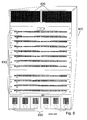
- FIG. 8 a front perspective view illustrates an apparatus 800 that contains front mounted horizontal modules 810.
- power supplies 830 are cooled from air flow from the front.
- Inlets 820 provide air to cool the rear mounted vertical modules of the apparatus 800.
- Openings 840 in each of the horizontal modules 810 provide an air path for cooling the horizontally mounted modules 810.
- FIG. 9 is a rear perspective view of the apparatus 800 of FIG. 8 .
- Vertically mounted modules 930 are cooled by an upper fan tray 920 pulling air from inlets 820 of FIG. 8 , then pushing that air downward across the surfaces of the vertically mounted modules 930.
- a lower fan tray 910 contains exhaust fans that pull the heated air from the vertically oriented modules 930, exhausting the heated air through plenums 960 formed below the lower fan tray to the rear of apparatus 800.
- An end closure 940 holding the vertically oriented modules 930 forms a plenum 950 on either side of the vertically oriented modules 930 to exhaust heated air from the horizontally oriented modules 810.
- FIG. 10 a top view shows the cooling path for the horizontal modules 810. Cool air is pulled in through the openings 840 shown in FIG. 8 , and pulled across the surface of the modules 810 to a radial blower 1020 mounted on either side of each of the modules 810. The radial blowers 1020 then exhaust the heated air through the plenums 950 to the rear of the apparatus 800. As in the apparatus 100 of FIG. 1 , a mid-plane 1010 connects the horizontally mounted modules 810 and the vertically mounted modules 930. Although described above as radial blowers, any desirable fan or blower can be used. The placement, configuration and number of blowers are by way of example and illustrative only, and other numbers configurations and placements can be used.
- FIG. 11 a side view in perspective, shows the cooling path for the vertical rear modules 930 described above and the cooling path 1110 for power supplies at the bottom of the apparatus 800.
- a plenum 1130 provides air passage from the front of the apparatus 800 through inlets 820 to the upper fan tray 920 which then pushes air vertically downward across the surfaces of the modules 930, where the lower fan tray 910 exhausts the air through plenum 960 to the rear of the apparatus 800.
- a wall 1120 provides a portion of an enclosure above the horizontally mounted modules 810 to form the plenum 1130.
Abstract
Description
- The present invention relates to the field of cooling systems, and in particular to cooling of a modular system with orthogonal modules.
- Systems that require very high bandwidth any-to-any connectivity among a set of modules typically use an orthogonal mid-plane configuration. In this configuration, a set of cards are plugged into the front side of the mid-plane in vertical configuration and another set of cards are plugged into the rear side of the mid-plane in horizontal configuration. This layout enables each front card to be directly connected to each rear card, and makes it possible to eliminate the use of PCB signal traces on the mid-plane to carry high speed signals.
- However, the orthogonal configuration also creates a cooling challenge, especially in applications where front-to-back cooling is required. Vertical cards can be cooled using conventional cooling mechanisms with front air intake and rear air exhaust, but cooling the horizontal cards while maintaining overall front-to-back air flow is challenging.
- If front-to-back cooling is not required, the horizontal card cage can be cooled using side-to-side air flow. However, many rack mount environments require front-to-back air cooling. One solution has been to divert air taken from a front intake to the back and run it up in a column next to the horizontal cards. Such a mechanism typically uses a set of fans or blowers to create the air pressure across the horizontal cards. However, the amount of air flow that is provided in such a system is typically limited due the number of turns in the air path. Also, the placement of one or two fan blades along the sides of the horizontal cards can severely limit the PCB area and panel surface that is available.
- In one embodiment, a method of cooling an apparatus comprises: forming a plenum on a side of a first chamber of the apparatus, open to a front of the apparatus, partitioning the apparatus with an air-permeable barrier, forming a second chamber separated from the plenum and the first chamber by the air-permeable barrier, pulling air from the front of the apparatus via the plenum through the air-permeable barrier into the second chamber, and exhausting air from the second chamber to a rear of the apparatus.
- In another embodiment, a method of cooling an apparatus comprises: cooling a first plurality of modules oriented in a first direction, comprising: pushing air from an edge of each of the first plurality of modules in the first direction, and pulling air from an opposite edge of each of the first plurality of modules in the first direction, and cooling a second plurality of modules oriented in a second direction, orthogonal to the first direction, comprising: moving air in the second direction across the second plurality of modules and through a plenum extending exterior to a first chamber containing the first plurality of modules, and exhausting air from the apparatus.
- In yet another embodiment, a method of cooling an apparatus comprises: forming a plenum on a side of a first chamber containing a first plurality of modules, moving air from a front of the apparatus through the plenum into a second chamber containing a second plurality of modules, the second plurality of modules mounted orthogonal to the first plurality of modules, and exhausting air to a rear of the apparatus from the second chamber.
- In yet another embodiment, a cooling system for an apparatus comprises: a first chamber, a plenum formed exterior to the first chamber and fluidly isolated from the first chamber, a second chamber in fluid communication with the plenum, a cooling system for the first chamber, comprising: a first fan, configured to push air across the first chamber, and a second fan, configured to pull air from the first chamber, and a cooling system for the second chamber, comprising: a third fan, configured to move air through the plenum into the second chamber.
- In yet another embodiment, a method of cooling an apparatus comprises: forming a first plenum on a side of a first chamber containing a first plurality of modules, moving air from a front of the apparatus across a second plurality of modules, the second plurality of modules mounted orthogonal to the first plurality of modules in a second chamber, and exhausting air from the second plurality of modules through the first plenum to a rear of the apparatus.
- The accompanying drawings, which are incorporated in and constitute a part of this specification, illustrate an implementation of apparatus and methods consistent with the present invention and, together with the detailed description, serve to explain advantages and principles consistent with the invention. In the drawings,
-
Fig. 1 is a top perspective view illustrating an apparatus with orthogonal modules according to one embodiment; -
Fig. 2 is a rear perspective view of the apparatus ofFig. 1 ; -
Fig. 3 is a front perspective view of the apparatus ofFig. 1 ; -
Fig. 4 is a side cutaway perspective view of the apparatus ofFig. 1 ; -
Fig. 5 is a perspective view illustrating another embodiment of an apparatus with orthogonal modules; -
Figs. 6-7 are additional perspective vies of the apparatus ofFig. 5 ; -
Fig. 8 is a front perspective view illustrating yet another embodiment of an apparatus with orthogonal modules; -
Fig. 9 is a rear perspective view of the apparatus ofFig. 8 ; -
Fig. 10 is a top perspective view of the apparatus ofFig. 8 ; and -
Fig. 11 is a side cutaway perspective of the apparatus ofFig. 8 . -
FIG. 1 is a top perspective view illustrating anapparatus 100 with orthogonal modules according to one embodiment. Theapparatus 100 can be, for example, an enterprise class router, and the modules are typically circuit boards. But the disclosed technique can be used in any apparatus with orthogonal modules. In this embodiment, theapparatus 100 contains a plurality ofmodules 110 oriented vertically in a front section of theapparatus 100 and a plurality ofmodules 130 oriented in a horizontal direction in a rear section of theapparatus 100.Modules vertical modules 110 are enclosed by anenclosure 170 on either side forming aplenum 150 on either side of thevertical modules 110 extending from the front of theapparatus 100 past the mid-plane 120. An air-permeable barrier 160 is placed between each of themodules 130, forming a rear chamber of theapparatus 100. In some embodiments,barrier 160 is a perforated rippled material where the perforation pattern can be figured to create a pressure difference between the front section on one side of thebarrier 160 and the rear section on the other side of thebarrier 160. This pressure difference can achieve a more uniform air flow across more of the surface area ofmodules 130. As shown inFIG. 1 , fans or blowers 140 are placed at a rear portion of themodules 130. The fans or blowers 140 pull air from the front of theapparatus 100 through theplenum 150 and through thebarrier 160 across themodules 130 providing cooling to themodules 130. Heated air is then exhausted through openings on the rear of theapparatus 100 as described below. As shown inFIG. 1 , in some embodiments, two blowers 140 are positioned centrally at the rear of eachmodule 130. In other embodiments, a single fan or blower 140 could be used. Alternately, the fan or fans 140 could be positioned in other locations on themodules 130 as desirable for uniform air flow across the surface of themodules 130 or to provide higher air flow across portions of the surface area of themodules 130 that generate proportionally more heat than other portions of themodules 130. - Turning to
FIG. 2 , a front view of theapparatus 100 shows theplenums 150 on either side of theenclosure 170 surrounding the verticallyoriented modules 110. Additionally,FIG. 2 shows an independent cooling system for themodules 110. Aplenum 240 is formed beneath the verticallyoriented modules 110 and alower fan tray 220 contains a plurality of fans that push air vertically across the surfaces of themodules 110 to provide cooling to themodules 110. Anupper fan tray 230 contains a plurality of fans that pull heated air from themodules 110 and exhaust the heated air toward the rear of theapparatus 100 as described below. A plurality ofpower supplies 210 are shown inFIG. 2 at the bottom of theapparatus 100. In some embodiments, each of these power supply units provides its own front-to-back air cooling path from front openings or inlets in thepower supply units 210. - Turning to
FIG. 3 , a rear view in perspective of theapparatus 100 illustrates the outlets where heated air is exhausted to the rear of theapparatus 100. A collection of powersupply exhaust outlets 310 correspond to thepower supply inlets 210 ofFIG. 2 . A pair ofexhaust outlets 330 is also shown for each of themodules 130, corresponding to the two fans or blowers 140 illustrated inFIG. 1 . Finally,outlets 320 provide exhaust outlets for heated air that have cooled thevertical modules 110 and is exhausted from theupper fan tray 230. -
FIG. 4 illustrates the air flow path across thevertical modules 110. As shown inFIG. 4 , anupper plenum 410 is formed above theupper fan tray 230 and the horizontally orientedmodules 130 to provide an air path to theexhaust ports 320 illustrated inFIG. 3 . - In another embodiment, instead of pulling air from the front of the
apparatus 100 across thehorizontal modules 130, as illustrated inFIG. 1 ,apparatus 500 pushes air across horizontal modules. One or more blowers orfans 510 are positioned toward the front of theapparatus 500 in aplenum 520. Thefans 510 push air through theplenum 520 formed along the side of vertical modules, not shown inFIG. 5 for clarity of the drawing. Putting thefans 510 in theplenum 520 can allow for better filtering and cleaner air throughout the air path across the rear horizontally mounted modules than the negative pressure system illustrated inFIGS. 1-4 . In some embodiments, filters can be placed at the inlets of theplenum 520 in front of thefans 510, but are not shown inFIG. 5 for clarity of the drawing. Abarrier 530 is placed at the outlets of thefans 510. As best shown inFIG. 7 , openings 710 are formed in thebarrier 530 to better control air flow through theplenum 520. Air pushed through theplenum 520 is then pushed across the surfaces of thehorizontal outlets 540 and exhausted through the rear of theapparatus 500. As shown inFIGS. 5 and6 , theapparatus 500 has a cooling system for the vertically oriented modules that is same as illustratedFIGS. 1-4 . The only difference between the embodiments ofFIGS. 1-4 andFIGS. 5-7 is that instead of pulling the air through the plenum and across the cards as inFIGS. 1-4 , theapparatus 500 pushes the air from the front through theplenum 520 and across thecards 540. The numbered configuration and placement of fans shown inFIGS. 5-7 are by way of example and illustrative only and other numbers configuration and placement of fans can be used. - In
apparatus 100, as illustrated inFIGS. 1-4 (and similarly inapparatus 500, illustrated inFIGS. 5-7 ), the vertically orientedmodules 110 are in a front section of theapparatus 100 and horizontally mountedmodules 130 are positioned in a rear section of theapparatus 100. In other embodiments, vertically oriented modules can be placed in the rear, and horizontally oriented modules can be placed in the front of the apparatus.FIGS. 8-11 illustrate such an apparatus according to one embodiment. - Turning now to
FIG. 8 , a front perspective view illustrates anapparatus 800 that contains front mountedhorizontal modules 810. As withapparatus 100,power supplies 830 are cooled from air flow from the front.Inlets 820 provide air to cool the rear mounted vertical modules of theapparatus 800.Openings 840 in each of thehorizontal modules 810 provide an air path for cooling the horizontally mountedmodules 810. -
FIG. 9 is a rear perspective view of theapparatus 800 ofFIG. 8 . Vertically mountedmodules 930 are cooled by anupper fan tray 920 pulling air frominlets 820 ofFIG. 8 , then pushing that air downward across the surfaces of the vertically mountedmodules 930. Alower fan tray 910 contains exhaust fans that pull the heated air from the vertically orientedmodules 930, exhausting the heated air throughplenums 960 formed below the lower fan tray to the rear ofapparatus 800. Anend closure 940 holding the vertically orientedmodules 930 forms aplenum 950 on either side of the vertically orientedmodules 930 to exhaust heated air from the horizontally orientedmodules 810. - Turning to
FIG. 10 , a top view shows the cooling path for thehorizontal modules 810. Cool air is pulled in through theopenings 840 shown inFIG. 8 , and pulled across the surface of themodules 810 to aradial blower 1020 mounted on either side of each of themodules 810. Theradial blowers 1020 then exhaust the heated air through theplenums 950 to the rear of theapparatus 800. As in theapparatus 100 ofFIG. 1 , a mid-plane 1010 connects the horizontally mountedmodules 810 and the vertically mountedmodules 930. Although described above as radial blowers, any desirable fan or blower can be used. The placement, configuration and number of blowers are by way of example and illustrative only, and other numbers configurations and placements can be used. -
FIG. 11 , a side view in perspective, shows the cooling path for the verticalrear modules 930 described above and thecooling path 1110 for power supplies at the bottom of theapparatus 800. Aplenum 1130 provides air passage from the front of theapparatus 800 throughinlets 820 to theupper fan tray 920 which then pushes air vertically downward across the surfaces of themodules 930, where thelower fan tray 910 exhausts the air throughplenum 960 to the rear of theapparatus 800. Awall 1120 provides a portion of an enclosure above the horizontally mountedmodules 810 to form theplenum 1130. - Aspects of the subject matter described herein are set out in the following numbered clauses:
- 1. A method of cooling an apparatus, comprising:
- forming a plenum on a side of a first chamber of the apparatus, open to a front of the apparatus;
- partitioning the apparatus with an air-permeable barrier, forming a second chamber separated from the plenum and the first chamber by the air-permeable barrier;
- pulling air from the front of the apparatus via the plenum through the air-permeable barrier into the second chamber; and
- exhausting air from the second chamber to a rear of the apparatus.
- 2. The method of
clause 1,
wherein the first chamber contains a first plurality of modules, and
wherein the second chamber contains a second plurality of modules, oriented orthogonally to the first plurality of modules. - 3. The method of
clause 1, further comprising:- cooling the first chamber independently of the second chamber.
- 4. The method of
clause 1, further comprising:- cooling a power supply for the apparatus independently of the second chamber.
- 5. A method of cooling an apparatus, comprising:
- cooling a first plurality of modules oriented in a first direction, comprising:
- pushing air from an edge of each of the first plurality of modules in the first direction; and
- pulling air from an opposite edge of each of the first plurality of modules in the first direction; and
- cooling a second plurality of modules oriented in a second direction, orthogonal to the first direction, comprising:
- moving air in the second direction across the second plurality of modules and through a plenum extending exterior to a first chamber containing the first plurality of modules; and
- exhausting air from the apparatus.
- cooling a first plurality of modules oriented in a first direction, comprising:
- 6. The method of clause 5, wherein the first direction is vertical relative to a floor on which the apparatus is positioned.
- 7. The method of clause 5, wherein the second direction is horizontal relative to a floor on which the apparatus is positioned.
- 8. The method of clause 5, cooling a first plurality of modules further comprising:
- exhausting air in the second direction exterior to a second chamber containing the second plurality of modules.
- 9. The method of clause 5, cooling the second plurality of modules further comprising:
- positioning an air-permeable barrier across a portion of each of the second plurality of modules, forming a side of a second chamber containing the second plurality of modules.
- generating a negative air pressure across the air-permeable barrier.
- 10. The method of clause 5, wherein the second plurality of modules is cooled independently of the first plurality of modules.
- 11. The method of clause 5,
wherein cooling the first plurality of modules pulls air from a front of the apparatus and exhausts air at a back of the apparatus, and
wherein cooling the second plurality of modules pulls air from the front of the apparatus and exhausts air at the back of the apparatus. - 12. A method of cooling an apparatus, comprising:
- forming a plenum on a side of a first chamber containing a first plurality of modules;
- moving air from a front of the apparatus through the plenum into a second chamber containing a second plurality of modules, the second plurality of modules mounted orthogonal to the first plurality of modules; and
- exhausting air to a rear of the apparatus from the second chamber.
- 13. The method of clause 12, moving air into the second chamber comprising:
- pushing air from the front of the apparatus through the plenum into the second chamber.
- 14. The method of clause 12, moving air into the second chamber comprising:
- positioning a fan on a rear portion of each of the second plurality of modules; and
- pulling air from the front of the apparatus through the plenum to the fan.
- 15. The method of clause 12, moving air into the second chamber comprising:
- pulling air from the front of the apparatus through the plenum across the second plurality of modules.
- 16. A cooling system for an apparatus, comprising:
- a first chamber;
- a plenum formed exterior to the first chamber and fluidly isolated from the first chamber;
- a second chamber in fluid communication with the plenum;
- a cooling system for the first chamber, comprising:
- a first fan, configured to push air across the first chamber; and
- a second fan, configured to pull air from the first chamber; and
- a cooling system for the second chamber, comprising:
- a third fan, configured to move air between the plenum and the second chamber.
- 17. The system of clause 16, further comprising:
- a plurality of modules, disposed in the second chamber so that the air moved by the third fan traverses the plurality of modules,
- wherein the third fan is mounted on one of the plurality of modules.
- 18. The system of clause 16, wherein the third fan is disposed in the plenum and is configured to push air through the plenum into the second chamber.
- 19. The system of clause 18, further comprising:
- a partition formed in the plenum, between the third fan and the second chamber; and
- an opening formed in the partition and aligned with the third fan to allow the third fan to push air through the opening.
- 20. The system of clause 16, the second chamber comprising:
- an air-permeable barrier configured to create an air pressure difference between either side of the barrier, positioned between the plenum and the second chamber.
- 21. The system of clause 20, wherein the second chamber has a negative air pressure relative to the plenum.
- 22. A method of cooling an apparatus comprising:
- forming a first plenum on a side of a first chamber containing a first plurality of modules;
- moving air from a front of the apparatus across a second plurality of modules, the second plurality of modules mounted orthogonal to the first plurality of modules in a second chamber; and
- exhausting air from the second plurality of modules through the first plenum to a rear of the apparatus.
- 23. The method of clause 22, further comprising:
- forming a second plenum above the second chamber and above the first chamber between the front of the apparatus and the first chamber;
- moving air from the second plenum across the first plurality of modules;
- exhausting air from the second chamber to a rear of the apparatus.
- 24. A method of cooling an apparatus, comprising:
- cooling a first plurality of modules oriented in a first direction, comprising:
- pushing air from an edge of each of the first plurality of modules in the first direction; and
- pulling air from an opposite edge of each of the first plurality of modules in the first direction; and
- cooling a second plurality of modules oriented in a second direction, orthogonal to the first direction, comprising:
- moving air in the second direction across the second plurality of modules and through a plenum extending exterior to a first chamber containing the first plurality of modules; and
- exhausting air from the apparatus.
- cooling a first plurality of modules oriented in a first direction, comprising:
- 25. The method of clause 24, wherein the first direction is vertical relative to a floor on which the apparatus is positioned.
- 26. The method of clause 24 or 25, wherein the second direction is horizontal relative to a floor on which the apparatus is positioned.
- 27. The method of any of clauses 24 to 26, cooling a first plurality of modules comprising:
- exhausting air in the second direction exterior to a second chamber containing the second plurality of modules.
- 28. The method of any of clauses 24 to 27, cooling the second plurality of modules comprising:
- positioning an air-permeable barrier across a portion of each of the second plurality of modules, forming a side of a second chamber containing the second plurality of modules.
- generating a negative air pressure across the air-permeable barrier.
- 29. The method of any of clauses 24 to 28, wherein the second plurality of modules is cooled independently of the first plurality of modules.
- 30. The method of any of clauses 24 to 29,
wherein cooling the first plurality of modules pulls air from a front of the apparatus and exhausts air at a back of the apparatus, and
wherein cooling the second plurality of modules pulls air from the front of the apparatus and exhausts air at the back of the apparatus. - 31. The method of clause 24, comprising:
- forming the plenum on a side of a first chamber containing the first plurality of modules;
- moving air from a front of the apparatus through the plenum into a second chamber containing the second plurality of modules; and
- exhausting air to a rear of the apparatus from the second chamber.
- 32. The method of clause 31, moving air into the second chamber comprising:
- pushing air from the front of the apparatus through the plenum into the second chamber.
- 33. A cooling system for an apparatus, comprising:
- a first chamber;
- a plenum formed exterior to the first chamber and fluidly isolated from the first chamber;
- a second chamber in fluid communication with the plenum;
- a cooling system for the first chamber, comprising:
- a first fan, configured to push air across the first chamber; and
- a second fan, configured to pull air from the first chamber; and
- a cooling system for the second chamber, comprising:
- a third fan, configured to move air between the plenum and the second chamber.
- 34. The system of clause 33, comprising:
- a plurality of modules, disposed in the second chamber so that the air moved by the third fan traverses the plurality of modules,
- wherein the third fan is mounted on one of the plurality of modules.
- 35. The system of clause 33 or 34, wherein the third fan is disposed in the plenum and is configured to push air through the plenum into the second chamber.
- 36. The system of clause 35, comprising:
- a partition formed in the plenum, between the third fan and the second chamber; and
- an opening formed in the partition and aligned with the third fan to allow the third fan to push air through the opening.
- 37. The system of any of clauses 33 to36, the second chamber comprising:
- an air-permeable barrier configured to create an air pressure difference between either side of the barrier, positioned between the plenum and the second chamber.
- 38. The system of clause 37, wherein the second chamber has a negative air pressure relative to the plenum.
- While certain example embodiments have been described in details and shown in the accompanying drawings, it is to be understood that such embodiments are merely illustrative of and not devised without departing from the basic scope thereof, which is determined by the claims that follow. By way of example and not limitation, the specific electrical components utilized may be replaced by known equivalents or other arrangements of components which function similarly and provide substantially the same result.
Claims (15)
- An apparatus, comprising:a housing defining a first chamber and a second chamber,the first chamber configured to contain a first plurality of modules,the second chamber configured to contain a second plurality of modules oriented orthogonally to the first plurality of modules,the housing defining a plenum disposed on a side of the first chamber; anda fan disposed within the housing, the fan configured to move air through the plenum into the second chamber and across at least a portion of a module from the second plurality of modules.
- The apparatus of claim 1, further comprising:a plurality of fans including the fan, each fan from the plurality of fans being vertically disposed within the plenum; andan air permeable barrier disposed within the plenum, each fan from the plurality of fans being disposed between the air permeable barrier and an opening of the plenum.
- The apparatus of claim 1 or 2, wherein the plenum is a first plenum, the side of the first chamber is a first side of the first chamber, and the housing defines a second plenum disposed on a second side of the first chamber.
- The apparatus of claim 1 or 2, wherein the plenum is a first plenum disposed on a vertical side of the first chamber , and the housing defies a second plenum disposed on a horizontal side of the first chamber.
- The apparatus of any preceding claim, wherein the plenum is a first plenum, the side of the first chamber is a first side, and the housing defines a second plenum disposed on a second side of the first chamber, the apparatus further comprising:an air permeable barrier disposed between the fan and an opening of the first plenum.
- The apparatus of any preceding claim, wherein the plenum is a first plenum, the side of the first chamber is a first side, the housing defines a second plenum disposed on a second side of the first chamber, the fan is disposed within the first plenum, the apparatus further comprising:an air permeable barrier disposed within the first plenum, the fan disposed between the air permeable barrier and an opening of the first plenum.
- The apparatus of any preceding claim, wherein the plenum is a first plenum, the side of the first chamber is a first side, the fan is a first fan, the housing defines a second plenum disposed on a second side of the first chamber, the apparatus further comprising:a second fan configured to move air through the second plenum into the first chamber, and across at least a portion of a module from the first plurality of modules.
- The apparatus of any preceding claim, wherein the fan is a first fan, the apparatus further comprising a second fan disposed within the housing, the second fan configured to move air across at least a portion of a module from the first plurality of modules.
- The apparatus of any preceding claim, wherein the fan is disposed on a module from the second plurality of modules.
- The apparatus of any preceding claim, wherein the fan is disposed on a module from the second plurality of modules, the apparatus further comprising:an air permeable barrier disposed between the fan and an opening of the plenum.
- The apparatus of claim 1, wherein the fan is a first fan, the apparatus further comprising:a second fan disposed within the housing; anda third fan disposed within the housing, the first plurality of modules being disposed between the second fan and the third fan, the second fan and the third fan collectively configured to move air across at least a portion of a module from the first plurality of modules.
- The apparatus of any preceding claim, wherein:the plenum defines at least a portion of a first cooling path including at least a portion of a module from the second plurality of modules;the side of the first chamber is a first side of the first chamber; andthe housing defines an opening disposed on a second side of the first chamber, the opening defining at least a portion of a second cooling path including at least a portion of a module from the first plurality of modules, such that within the housing the second cooling path is fluidically isolated from the first cooling path.
- The apparatus of any preceding claim, wherein the plenum is exterior to the first chamber such that the first chamber is fluidically isolated from the plenum within the housing.
- The apparatus of any preceding claim, wherein the first chamber is a front chamber, the second chamber is a rear chamber, and the fan is configured to draw air from a front of the apparatus via an opening of the plenum.
- The apparatus of any preceding claim, wherein the fan is a first fan configured to move air from a front of the apparatus via an opening of the first plenum across the second plurality of modules to an first exhaust opening at a rear of the apparatus, the apparatus further comprising:a second fan configured to move air from the front of the apparatus via an opening into the first chamber across the first plurality of modules to a second exhaust opening at a rear of the apparatus.
Applications Claiming Priority (2)
| Application Number | Priority Date | Filing Date | Title |
|---|---|---|---|
| US12/167,604 US7826222B2 (en) | 2008-07-03 | 2008-07-03 | Front-to-back cooling system for modular systems with orthogonal midplane configuration |
| EP08252855.5A EP2141974B1 (en) | 2008-07-03 | 2008-08-28 | Front-to-back cooling system for modular systems with orthogonal midplane configuration |
Related Parent Applications (1)
| Application Number | Title | Priority Date | Filing Date |
|---|---|---|---|
| EP08252855.5A Division EP2141974B1 (en) | 2008-07-03 | 2008-08-28 | Front-to-back cooling system for modular systems with orthogonal midplane configuration |
Publications (3)
| Publication Number | Publication Date |
|---|---|
| EP2720524A2 true EP2720524A2 (en) | 2014-04-16 |
| EP2720524A3 EP2720524A3 (en) | 2017-04-12 |
| EP2720524B1 EP2720524B1 (en) | 2020-03-18 |
Family
ID=41208645
Family Applications (2)
| Application Number | Title | Priority Date | Filing Date |
|---|---|---|---|
| EP14151003.2A Active EP2720524B1 (en) | 2008-07-03 | 2008-08-28 | Front-to-back cooling system for modular systems with orthogonal midplane configuration |
| EP08252855.5A Active EP2141974B1 (en) | 2008-07-03 | 2008-08-28 | Front-to-back cooling system for modular systems with orthogonal midplane configuration |
Family Applications After (1)
| Application Number | Title | Priority Date | Filing Date |
|---|---|---|---|
| EP08252855.5A Active EP2141974B1 (en) | 2008-07-03 | 2008-08-28 | Front-to-back cooling system for modular systems with orthogonal midplane configuration |
Country Status (3)
| Country | Link |
|---|---|
| US (4) | US7826222B2 (en) |
| EP (2) | EP2720524B1 (en) |
| CN (2) | CN101621913B (en) |
Families Citing this family (98)
| Publication number | Priority date | Publication date | Assignee | Title |
|---|---|---|---|---|
| US8064200B1 (en) * | 2008-04-16 | 2011-11-22 | Cyan Optics, Inc. | Cooling a chassis by moving air through a midplane between two sets of channels oriented laterally relative to one another |
| US10058011B2 (en) * | 2008-06-19 | 2018-08-21 | Panduit Corp. | Passive cooling systems for network cabinet |
| US7826222B2 (en) * | 2008-07-03 | 2010-11-02 | Juniper Networks, Inc. | Front-to-back cooling system for modular systems with orthogonal midplane configuration |
| US7804684B1 (en) | 2008-12-22 | 2010-09-28 | Juniper Networks, Inc. | Cooling system for a data processing unit |
| US8798045B1 (en) | 2008-12-29 | 2014-08-05 | Juniper Networks, Inc. | Control plane architecture for switch fabrics |
| US8535787B1 (en) | 2009-06-29 | 2013-09-17 | Juniper Networks, Inc. | Heat sinks having a thermal interface for cooling electronic devices |
| US8534930B1 (en) | 2009-09-24 | 2013-09-17 | Juniper Networks, Inc. | Circuit boards defining openings for cooling electronic devices |
| US8801374B1 (en) | 2009-10-07 | 2014-08-12 | Juniper Networks, Inc. | Fan trays having stator blades for improving air flow performance |
| US8705500B1 (en) | 2009-11-05 | 2014-04-22 | Juniper Networks, Inc. | Methods and apparatus for upgrading a switch fabric |
| US8223498B2 (en) * | 2009-11-11 | 2012-07-17 | Juniper Networks, Inc. | Thermal interface members for removable electronic devices |
| KR101712100B1 (en) * | 2010-01-12 | 2017-03-03 | 삼성전자 주식회사 | Cooling system and display apparatus using the same |
| US8279601B2 (en) * | 2010-01-28 | 2012-10-02 | Juniper Networks, Inc. | Air flow ducts for cooling electronic devices within a data processing unit |
| US8694654B1 (en) * | 2010-03-23 | 2014-04-08 | Juniper Networks, Inc. | Host side protocols for use with distributed control plane of a switch |
| US9716672B2 (en) | 2010-05-28 | 2017-07-25 | Brocade Communications Systems, Inc. | Distributed configuration management for virtual cluster switching |
| US8867552B2 (en) | 2010-05-03 | 2014-10-21 | Brocade Communications Systems, Inc. | Virtual cluster switching |
| US9270486B2 (en) | 2010-06-07 | 2016-02-23 | Brocade Communications Systems, Inc. | Name services for virtual cluster switching |
| US9769016B2 (en) | 2010-06-07 | 2017-09-19 | Brocade Communications Systems, Inc. | Advanced link tracking for virtual cluster switching |
| DE202010007046U1 (en) * | 2010-05-20 | 2010-08-26 | Fujitsu Technology Solutions Intellectual Property Gmbh | Rack housing for receiving a plurality of fanless insertion components |
| US9628293B2 (en) | 2010-06-08 | 2017-04-18 | Brocade Communications Systems, Inc. | Network layer multicasting in trill networks |
| US9608833B2 (en) | 2010-06-08 | 2017-03-28 | Brocade Communications Systems, Inc. | Supporting multiple multicast trees in trill networks |
| US9806906B2 (en) | 2010-06-08 | 2017-10-31 | Brocade Communications Systems, Inc. | Flooding packets on a per-virtual-network basis |
| US9807031B2 (en) | 2010-07-16 | 2017-10-31 | Brocade Communications Systems, Inc. | System and method for network configuration |
| US8718063B2 (en) | 2010-07-26 | 2014-05-06 | Juniper Networks, Inc. | Methods and apparatus related to route selection within a network |
| TW201209551A (en) * | 2010-08-18 | 2012-03-01 | Hon Hai Prec Ind Co Ltd | Container data center |
| JP5315323B2 (en) * | 2010-11-17 | 2013-10-16 | アラクサラネットワークス株式会社 | Electronic equipment |
| US9282060B2 (en) | 2010-12-15 | 2016-03-08 | Juniper Networks, Inc. | Methods and apparatus for dynamic resource management within a distributed control plane of a switch |
| US8560660B2 (en) | 2010-12-15 | 2013-10-15 | Juniper Networks, Inc. | Methods and apparatus for managing next hop identifiers in a distributed switch fabric system |
| US9391796B1 (en) | 2010-12-22 | 2016-07-12 | Juniper Networks, Inc. | Methods and apparatus for using border gateway protocol (BGP) for converged fibre channel (FC) control plane |
| US9106527B1 (en) | 2010-12-22 | 2015-08-11 | Juniper Networks, Inc. | Hierarchical resource groups for providing segregated management access to a distributed switch |
| US9253928B2 (en) | 2011-06-27 | 2016-02-02 | Henkel IP & Holding GmbH | Cooling module with parallel blowers |
| US8767400B2 (en) * | 2011-06-27 | 2014-07-01 | The Bergquist Torrington Company | Cooling module with parallel blowers |
| US8854814B2 (en) * | 2011-06-27 | 2014-10-07 | Futurewei Technologies, Inc. | Hybrid cooling design for modular systems |
| US9039432B2 (en) | 2011-07-08 | 2015-05-26 | Cisco Technology, Inc. | System and method for high connectivity platform |
| US9736085B2 (en) | 2011-08-29 | 2017-08-15 | Brocade Communications Systems, Inc. | End-to end lossless Ethernet in Ethernet fabric |
| CN102510707B (en) | 2011-11-01 | 2014-08-13 | 华为技术有限公司 | Cooling system and electronic device with same |
| US9699117B2 (en) | 2011-11-08 | 2017-07-04 | Brocade Communications Systems, Inc. | Integrated fibre channel support in an ethernet fabric switch |
| US9450870B2 (en) | 2011-11-10 | 2016-09-20 | Brocade Communications Systems, Inc. | System and method for flow management in software-defined networks |
| US9565159B2 (en) | 2011-12-21 | 2017-02-07 | Juniper Networks, Inc. | Methods and apparatus for a distributed fibre channel control plane |
| JP5927911B2 (en) * | 2011-12-28 | 2016-06-01 | 富士通株式会社 | COOLING UNIT, COOLING UNIT CASES, AND ELECTRONIC DEVICE |
| US9742693B2 (en) | 2012-02-27 | 2017-08-22 | Brocade Communications Systems, Inc. | Dynamic service insertion in a fabric switch |
| US9154416B2 (en) | 2012-03-22 | 2015-10-06 | Brocade Communications Systems, Inc. | Overlay tunnel in a fabric switch |
| EP2645836A1 (en) * | 2012-03-30 | 2013-10-02 | Alcatel Lucent | Mounting arrangement for orthogonally mounting plug-in cards |
| US9560793B2 (en) * | 2012-04-27 | 2017-01-31 | Hewlett Packard Enterprise Development Lp | Blade enclosure |
| US8693195B2 (en) | 2012-05-01 | 2014-04-08 | Hewlett-Packard Development Company, L.P. | Chassis apparatus protruding electronic devices |
| US10277464B2 (en) | 2012-05-22 | 2019-04-30 | Arris Enterprises Llc | Client auto-configuration in a multi-switch link aggregation |
| US9461768B2 (en) * | 2012-05-23 | 2016-10-04 | Brocade Communications Systems, Inc. | Terabit top-of-rack switch |
| US9148975B2 (en) * | 2012-06-22 | 2015-09-29 | Advanced Micro Devices, Inc. | Electronic interconnect method and apparatus |
| US8885341B2 (en) | 2012-08-28 | 2014-11-11 | Motorola Mobility Llc | Compact front to back horizontal cooling for rack mounted chassis |
| JP5829992B2 (en) * | 2012-09-27 | 2015-12-09 | 東芝三菱電機産業システム株式会社 | Electrical equipment storage device |
| US8922992B2 (en) * | 2012-11-12 | 2014-12-30 | Dell Products L.P. | System and design of cost effective chassis design for networking products |
| US9215831B2 (en) | 2012-11-22 | 2015-12-15 | Huawei Technologies Co., Ltd. | Heat dissipation system |
| CN103841792B (en) * | 2012-11-22 | 2017-04-12 | 华为技术有限公司 | Cooling system |
| US9548926B2 (en) | 2013-01-11 | 2017-01-17 | Brocade Communications Systems, Inc. | Multicast traffic load balancing over virtual link aggregation |
| US9413691B2 (en) | 2013-01-11 | 2016-08-09 | Brocade Communications Systems, Inc. | MAC address synchronization in a fabric switch |
| US9565099B2 (en) | 2013-03-01 | 2017-02-07 | Brocade Communications Systems, Inc. | Spanning tree in fabric switches |
| CN203423892U (en) * | 2013-05-23 | 2014-02-05 | 杭州华三通信技术有限公司 | Electronic device |
| US9912612B2 (en) | 2013-10-28 | 2018-03-06 | Brocade Communications Systems LLC | Extended ethernet fabric switches |
| CN203691803U (en) * | 2013-12-27 | 2014-07-02 | 中兴通讯股份有限公司 | Plug-in box and terminal |
| US9548873B2 (en) | 2014-02-10 | 2017-01-17 | Brocade Communications Systems, Inc. | Virtual extensible LAN tunnel keepalives |
| US10581758B2 (en) | 2014-03-19 | 2020-03-03 | Avago Technologies International Sales Pte. Limited | Distributed hot standby links for vLAG |
| US10476698B2 (en) | 2014-03-20 | 2019-11-12 | Avago Technologies International Sales Pte. Limited | Redundent virtual link aggregation group |
| US10063473B2 (en) | 2014-04-30 | 2018-08-28 | Brocade Communications Systems LLC | Method and system for facilitating switch virtualization in a network of interconnected switches |
| US9800471B2 (en) | 2014-05-13 | 2017-10-24 | Brocade Communications Systems, Inc. | Network extension groups of global VLANs in a fabric switch |
| US9603280B2 (en) | 2014-05-30 | 2017-03-21 | EMC IP Holding Company LLC | Flash module |
| US9622394B1 (en) | 2014-05-30 | 2017-04-11 | EMC IP Holding Company LLC | Electromagnetic interference containment system |
| US9362641B2 (en) | 2014-07-01 | 2016-06-07 | Telefonaktiebolaget L M Ericsson (Publ) | Orthogonal backplane design with reduced chassis depth |
| US10616108B2 (en) | 2014-07-29 | 2020-04-07 | Avago Technologies International Sales Pte. Limited | Scalable MAC address virtualization |
| US9807007B2 (en) | 2014-08-11 | 2017-10-31 | Brocade Communications Systems, Inc. | Progressive MAC address learning |
| US9699029B2 (en) | 2014-10-10 | 2017-07-04 | Brocade Communications Systems, Inc. | Distributed configuration management in a switch group |
| CN105592667A (en) * | 2014-10-24 | 2016-05-18 | 华为技术有限公司 | Network device |
| US9626255B2 (en) | 2014-12-31 | 2017-04-18 | Brocade Communications Systems, Inc. | Online restoration of a switch snapshot |
| US9628407B2 (en) | 2014-12-31 | 2017-04-18 | Brocade Communications Systems, Inc. | Multiple software versions in a switch group |
| US9942097B2 (en) | 2015-01-05 | 2018-04-10 | Brocade Communications Systems LLC | Power management in a network of interconnected switches |
| US10003552B2 (en) | 2015-01-05 | 2018-06-19 | Brocade Communications Systems, Llc. | Distributed bidirectional forwarding detection protocol (D-BFD) for cluster of interconnected switches |
| US10038592B2 (en) | 2015-03-17 | 2018-07-31 | Brocade Communications Systems LLC | Identifier assignment to a new switch in a switch group |
| US9807005B2 (en) | 2015-03-17 | 2017-10-31 | Brocade Communications Systems, Inc. | Multi-fabric manager |
| US9811969B2 (en) | 2015-03-30 | 2017-11-07 | Bally Gaming, Inc. | Removable fan assembly providing multi-directional air flow for a wagering game machine |
| US10579406B2 (en) | 2015-04-08 | 2020-03-03 | Avago Technologies International Sales Pte. Limited | Dynamic orchestration of overlay tunnels |
| WO2016175834A1 (en) * | 2015-04-30 | 2016-11-03 | Hewlett Packard Enterprise Development Lp | Cooling via a sleeve connector |
| US10439929B2 (en) | 2015-07-31 | 2019-10-08 | Avago Technologies International Sales Pte. Limited | Graceful recovery of a multicast-enabled switch |
| US10171303B2 (en) | 2015-09-16 | 2019-01-01 | Avago Technologies International Sales Pte. Limited | IP-based interconnection of switches with a logical chassis |
| US10299403B2 (en) * | 2015-09-23 | 2019-05-21 | Advanced Micro Devices, Inc. | Modular thermal solution for high-performance processors |
| JP6627438B2 (en) * | 2015-11-10 | 2020-01-08 | 富士通株式会社 | Cooling device and information processing device |
| US9912614B2 (en) | 2015-12-07 | 2018-03-06 | Brocade Communications Systems LLC | Interconnection of switches based on hierarchical overlay tunneling |
| MY178128A (en) * | 2016-01-07 | 2020-10-05 | Nokia Technologies Oy | Method of indication of available radio resources |
| US10365378B2 (en) * | 2016-02-29 | 2019-07-30 | Thermo Eberline Llc | Active dosimeter systems for real-time radiation dose measurements |
| KR102104383B1 (en) * | 2016-04-25 | 2020-04-24 | 주식회사 엘지화학 | Energy storage apparatus and method for cooling the energy storage apparatus |
| US9510486B1 (en) | 2016-07-13 | 2016-11-29 | Matteo B. Gravina | Data center cooling system having electrical power generation |
| US10237090B2 (en) | 2016-10-28 | 2019-03-19 | Avago Technologies International Sales Pte. Limited | Rule-based network identifier mapping |
| US9907213B1 (en) | 2016-12-12 | 2018-02-27 | Matteo B. Gravina | Data center cooling system having electrical power generation |
| US10020436B1 (en) | 2017-06-15 | 2018-07-10 | Matteo B. Gravina | Thermal energy accumulator for power generation and high performance computing center |
| CN107613728A (en) * | 2017-09-18 | 2018-01-19 | 北京百卓网络技术有限公司 | A kind of communication equipment with rear plug-in card and thereafter plug-in card |
| CN107708379A (en) * | 2017-09-18 | 2018-02-16 | 北京百卓网络技术有限公司 | A kind of service card and communication equipment |
| CN108235637B (en) * | 2017-12-15 | 2020-08-21 | 深圳市恒扬数据股份有限公司 | Vertical orthogonal system for communication equipment and communication equipment |
| US11096314B2 (en) | 2018-07-09 | 2021-08-17 | Cisco Technology, Inc. | Front accessible fan tray with front-to-back cooling in a modular electronic system |
| US10912216B1 (en) | 2018-09-26 | 2021-02-02 | Cisco Technology, Inc. | Bidirectional installation module for modular electronic system |
| KR20200051913A (en) * | 2018-11-05 | 2020-05-14 | 삼성전자주식회사 | Solid state drive device and computer server system having the same |
| WO2022192376A1 (en) * | 2021-03-11 | 2022-09-15 | Core Scientific, Inc. | System for cooling computing devices in an array |
Family Cites Families (87)
| Publication number | Priority date | Publication date | Assignee | Title |
|---|---|---|---|---|
| US3895215A (en) | 1973-11-23 | 1975-07-15 | Jerry Dale Gordon | Cabinet for holding food at a controllable temperature |
| US5079438A (en) * | 1989-01-30 | 1992-01-07 | Heung Lap Yan | Circuit module fan assembly |
| US4971143A (en) | 1989-05-22 | 1990-11-20 | Carrier Corporation | Fan stator assembly for heat exchanger |
| GB2293279B (en) * | 1994-09-14 | 1998-05-13 | Questech Ltd | Improvements in and relating to housings for electronic equipment |
| US5477416A (en) * | 1995-02-14 | 1995-12-19 | Hewlett-Packard Company | Enclosure with metered air ducts for mounting and cooling modules |
| US5699613A (en) | 1995-09-25 | 1997-12-23 | International Business Machines Corporation | Fine dimension stacked vias for a multiple layer circuit board structure |
| US5751549A (en) | 1996-06-26 | 1998-05-12 | Sun Microsystems, Inc. | Hard disk drive assembly which has a plenum chamber and a fan assembly that is perpendicular to a rack chamber |
| US5912801A (en) * | 1997-09-16 | 1999-06-15 | Excel, Inc. | Telecommunication switch chassis |
| US6452797B1 (en) | 1997-11-12 | 2002-09-17 | Intel Corporation | Fan-cooled card |
| US6565334B1 (en) | 1998-07-20 | 2003-05-20 | Phillip James Bradbury | Axial flow fan having counter-rotating dual impeller blade arrangement |
| US6163454A (en) * | 1999-02-22 | 2000-12-19 | Hewlett-Packard Company | Electromagnetic interference (EMI) shield for electrical components, an internal EMI barrier, and a storage enclosure for electrical/electronic components |
| DE20001236U1 (en) | 2000-01-25 | 2000-04-27 | Hsieh Hsin Mao | fan |
| US6280318B1 (en) | 2000-02-22 | 2001-08-28 | International Game Technology | Central forced air cooling of a gaming machine |
| US7369411B2 (en) | 2000-02-25 | 2008-05-06 | Thermagon, Inc. | Thermal interface assembly and method for forming a thermal interface between a microelectronic component package and heat sink |
| US6372997B1 (en) | 2000-02-25 | 2002-04-16 | Thermagon, Inc. | Multi-layer structure and method for forming a thermal interface with low contact resistance between a microelectronic component package and heat sink |
| US6293753B1 (en) | 2000-03-03 | 2001-09-25 | Motorola | Air moving apparatus and method of optimizing performance thereof |
| US6508595B1 (en) | 2000-05-11 | 2003-01-21 | International Business Machines Corporation | Assembly of opto-electronic module with improved heat sink |
| JP4397109B2 (en) * | 2000-08-14 | 2010-01-13 | 富士通株式会社 | Information processing apparatus and crossbar board unit / back panel assembly manufacturing method |
| US6449150B1 (en) * | 2000-11-13 | 2002-09-10 | Cisco Technology, Inc. | Method and system for cooling a card shelf |
| WO2002059965A1 (en) | 2001-01-22 | 2002-08-01 | Parker Hannifin Corporation | Clean release, phase change thermal interface |
| US6951707B2 (en) | 2001-03-08 | 2005-10-04 | Ppg Industries Ohio, Inc. | Process for creating vias for circuit assemblies |
| US6525935B2 (en) * | 2001-03-12 | 2003-02-25 | Appro International, Inc. | Low profile highly accessible computer enclosure with plenum for cooling high power processors |
| US6446707B1 (en) | 2001-04-17 | 2002-09-10 | Hewlett-Packard Company | Active heat sink structure with directed air flow |
| US6653755B2 (en) | 2001-05-30 | 2003-11-25 | Intel Corporation | Radial air flow fan assembly having stator fins surrounding rotor blades |
| US6462948B1 (en) | 2001-06-25 | 2002-10-08 | Intel Corporation | Thermal management system for a multiple processor computer appliance |
| US6508621B1 (en) | 2001-07-26 | 2003-01-21 | Hewlett-Packard Company | Enhanced performance air moving assembly |
| US20030033463A1 (en) | 2001-08-10 | 2003-02-13 | Garnett Paul J. | Computer system storage |
| US6904968B2 (en) * | 2001-09-14 | 2005-06-14 | Hewlett-Packard Development Company, L.P. | Method and apparatus for individually cooling components of electronic systems |
| US6603662B1 (en) | 2002-01-25 | 2003-08-05 | Sun Microsystems, Inc. | Computer cooling system |
| US6900387B2 (en) | 2002-01-30 | 2005-05-31 | Sun Microsystems, Inc. | Balanced flow cooling |
| US6628520B2 (en) | 2002-02-06 | 2003-09-30 | Hewlett-Packard Development Company, L.P. | Method, apparatus, and system for cooling electronic components |
| US6879486B1 (en) | 2002-02-14 | 2005-04-12 | Mercury Computer Systems, Inc. | Central inlet circuit board assembly |
| US7371965B2 (en) | 2002-05-09 | 2008-05-13 | Finisar Corporation | Modular cage with heat sink for use with pluggable module |
| US6549406B1 (en) | 2002-05-09 | 2003-04-15 | Sun Microsystems, Inc. | Fan tray assembly for an electronics enclosure |
| GB2389710B (en) | 2002-06-10 | 2006-02-08 | Sun Microsystems Inc | Electronics module |
| US6768640B2 (en) * | 2002-06-28 | 2004-07-27 | Sun Microsystems, Inc. | Computer system employing redundant cooling fans |
| US6721180B2 (en) | 2002-07-31 | 2004-04-13 | Infineon Technologies Ag | Cooling hood for circuit board |
| US6986679B1 (en) | 2002-09-14 | 2006-01-17 | Finisar Corporation | Transceiver module cage for use with modules of varying widths |
| US6932696B2 (en) * | 2003-01-08 | 2005-08-23 | Sun Microsystems, Inc. | Cooling system including redundant fan controllers |
| JP4012091B2 (en) * | 2003-02-20 | 2007-11-21 | 富士通株式会社 | Electronic device cooling structure and information processing apparatus |
| US6729905B1 (en) | 2003-03-12 | 2004-05-04 | Hon Hai Precision Ind. Co., Ltd. | Transceiver cage assembly |
| US7011504B2 (en) | 2003-04-04 | 2006-03-14 | Nidec America Corporation | Fan, fan guard and related method |
| US20040264145A1 (en) * | 2003-05-08 | 2004-12-30 | Miller Greg F. | Compact electronic component system and method |
| EP1480269A1 (en) | 2003-05-13 | 2004-11-24 | Agilent Technologies Inc | Printed Circuit Board with improved cooling of electrical component |
| US7112131B2 (en) | 2003-05-13 | 2006-09-26 | American Power Conversion Corporation | Rack enclosure |
| US6912131B2 (en) | 2003-08-27 | 2005-06-28 | Lucent Technologies Inc. | Electronic components card air deflector |
| TWI235205B (en) | 2003-10-31 | 2005-07-01 | Delta Electronics Inc | Centrifugal fan with stator blades |
| CA2588508A1 (en) * | 2003-11-18 | 2005-06-02 | Distributed Thermal Systems Ltd. | Series fans with flow modification element |
| US7158379B2 (en) | 2003-12-12 | 2007-01-02 | Cisco Technology, Inc. | Device for removing heat from a power connector |
| US7074123B2 (en) | 2004-01-13 | 2006-07-11 | Power Of 4, L.L.C. | Cabinet for computer devices with air distribution device |
| TW200528011A (en) | 2004-02-13 | 2005-08-16 | Asustek Comp Inc | Heat sink device inside electrical apparatus |
| US7145773B2 (en) | 2004-02-26 | 2006-12-05 | Nortel Networks Limited | Pluggable electronic module |
| US6980437B2 (en) | 2004-03-03 | 2005-12-27 | Tyco Electronics Corporation | Pluggable electronic receptacle with heat sink assembly |
| US7239515B2 (en) | 2004-03-08 | 2007-07-03 | Nortel Networks Limited | Thermal assembly for cooling an electronics module |
| US20050207134A1 (en) * | 2004-03-16 | 2005-09-22 | Belady Christian L | Cell board interconnection architecture |
| US7164581B2 (en) * | 2004-06-21 | 2007-01-16 | Computer Network Technology Corp. | Modular chassis divided along a midplane and cooling system therefor |
| US7209351B2 (en) * | 2004-06-30 | 2007-04-24 | Intel Corporation | Telecom equipment chassis using modular air cooling system |
| TWI288210B (en) | 2004-08-18 | 2007-10-11 | Delta Electronics Inc | Heat-dissipating fan and its housing |
| US7224582B1 (en) | 2004-09-20 | 2007-05-29 | Nortel Networks Limited | Floating heatsink for removable components |
| US7088583B2 (en) | 2004-10-25 | 2006-08-08 | International Business Machines Corporation | System for airflow management in electronic enclosures |
| WO2006054332A1 (en) * | 2004-11-16 | 2006-05-26 | Fujitsu Limited | Communication device and frame structure |
| US7280356B2 (en) * | 2004-12-14 | 2007-10-09 | Amphenol Corporation | Air cooling architecture for orthogonal board architectures |
| SE527918C2 (en) * | 2004-12-22 | 2006-07-11 | Dometic Sweden Ab | Apparatus box for computer and computer including such apparatus box |
| US7184268B2 (en) | 2005-01-10 | 2007-02-27 | Hewlett-Packard Development Company, L.P. | Dynamically adaptable electronics cooling fan |
| US7548421B2 (en) | 2005-10-25 | 2009-06-16 | Hewlett-Packard Development Company, L.P. | Impingement cooling of components in an electronic system |
| US7434412B1 (en) | 2005-10-27 | 2008-10-14 | Sun Microsystems, Inc. | Computer equipment temperature control system and methods for operating the same |
| US7420806B1 (en) | 2005-11-22 | 2008-09-02 | Juniper Networks, Inc. | Airflow distribution through an electronic device |
| US7295446B2 (en) | 2005-12-30 | 2007-11-13 | International Business Machines Corporation | Midplane connector for blades |
| US7629683B1 (en) * | 2006-02-28 | 2009-12-08 | Juniper Networks, Inc. | Thermal management of electronic devices |
| US7365976B2 (en) * | 2006-03-24 | 2008-04-29 | Fujitsu Limited | Electronic apparatus |
| US8952524B2 (en) | 2006-04-28 | 2015-02-10 | Juniper Networks, Inc. | Re-workable heat sink attachment assembly |
| US7394654B2 (en) | 2006-10-19 | 2008-07-01 | Cisco Technology, Inc. | Method and apparatus for providing thermal management in an electronic device |
| US7898808B2 (en) | 2007-03-23 | 2011-03-01 | Finisar Corporation | Mechanisms for heat transfer in an optical transceiver module and card cage system |
| US7813120B2 (en) | 2007-06-13 | 2010-10-12 | Hewlett-Packard Development Company, L.P. | Airflow path within an electronic module enclosure |
| JP4898598B2 (en) | 2007-08-28 | 2012-03-14 | 株式会社日立製作所 | Cooling structure of rack mount type control device and rack type storage control device |
| US7722359B1 (en) * | 2007-09-27 | 2010-05-25 | Emc Corporation | Connection assembly having midplane with enhanced connection and airflow features |
| US7751186B2 (en) | 2007-10-29 | 2010-07-06 | Dell Products L.P. | Chassis having a bypass channel for air flow |
| US20090116185A1 (en) | 2007-11-02 | 2009-05-07 | Hou-An Su | Small form-factor pluggable transceiver module housing |
| US7907402B2 (en) | 2007-11-09 | 2011-03-15 | Panduit Corp. | Cooling system |
| US7808792B2 (en) * | 2007-12-18 | 2010-10-05 | Juniper Networks, Inc. | Single fan tray in a midplane architecture |
| US8076773B2 (en) | 2007-12-26 | 2011-12-13 | The Bergquist Company | Thermal interface with non-tacky surface |
| US8064200B1 (en) * | 2008-04-16 | 2011-11-22 | Cyan Optics, Inc. | Cooling a chassis by moving air through a midplane between two sets of channels oriented laterally relative to one another |
| US7826222B2 (en) | 2008-07-03 | 2010-11-02 | Juniper Networks, Inc. | Front-to-back cooling system for modular systems with orthogonal midplane configuration |
| US7885066B2 (en) | 2008-07-17 | 2011-02-08 | Juniper Networks, Inc. | Airflow/cooling solution for chassis with orthogonal boards |
| US7804684B1 (en) * | 2008-12-22 | 2010-09-28 | Juniper Networks, Inc. | Cooling system for a data processing unit |
| US8223498B2 (en) | 2009-11-11 | 2012-07-17 | Juniper Networks, Inc. | Thermal interface members for removable electronic devices |
| US8279601B2 (en) | 2010-01-28 | 2012-10-02 | Juniper Networks, Inc. | Air flow ducts for cooling electronic devices within a data processing unit |
-
2008
- 2008-07-03 US US12/167,604 patent/US7826222B2/en active Active
- 2008-08-27 CN CN200810210571.2A patent/CN101621913B/en active Active
- 2008-08-27 CN CN201410456757.1A patent/CN104284565B/en active Active
- 2008-08-28 EP EP14151003.2A patent/EP2720524B1/en active Active
- 2008-08-28 EP EP08252855.5A patent/EP2141974B1/en active Active
-
2010
- 2010-09-23 US US12/889,039 patent/US20110056660A1/en not_active Abandoned
- 2010-09-23 US US12/889,075 patent/US8125779B2/en active Active
- 2010-09-23 US US12/889,111 patent/US8120912B2/en active Active
Non-Patent Citations (1)
| Title |
|---|
| None |
Also Published As
| Publication number | Publication date |
|---|---|
| US20110011567A1 (en) | 2011-01-20 |
| EP2141974B1 (en) | 2014-01-15 |
| US20110056660A1 (en) | 2011-03-10 |
| US20110011562A1 (en) | 2011-01-20 |
| CN104284565B (en) | 2017-05-31 |
| CN101621913A (en) | 2010-01-06 |
| EP2720524A3 (en) | 2017-04-12 |
| EP2141974A2 (en) | 2010-01-06 |
| US20100002382A1 (en) | 2010-01-07 |
| CN101621913B (en) | 2014-10-08 |
| EP2141974A3 (en) | 2011-01-12 |
| US7826222B2 (en) | 2010-11-02 |
| US8125779B2 (en) | 2012-02-28 |
| CN104284565A (en) | 2015-01-14 |
| EP2720524B1 (en) | 2020-03-18 |
| US8120912B2 (en) | 2012-02-21 |
Similar Documents
| Publication | Publication Date | Title |
|---|---|---|
| US7826222B2 (en) | Front-to-back cooling system for modular systems with orthogonal midplane configuration | |
| US7885066B2 (en) | Airflow/cooling solution for chassis with orthogonal boards | |
| US8064200B1 (en) | Cooling a chassis by moving air through a midplane between two sets of channels oriented laterally relative to one another | |
| US7808792B2 (en) | Single fan tray in a midplane architecture | |
| US7869209B2 (en) | Electronic rack combining natural convection and forced air circulation for its cooling | |
| US8154867B2 (en) | High density switching platform with interbay connections arrangement | |
| EP2391196B1 (en) | Cooling arrangement for a rack mounted processing device | |
| EP2590492B1 (en) | Cooling system and electronic device including the cooling system | |
| US7262962B1 (en) | Techniques for cooling multiple sets of circuit boards connected by a midplane | |
| EP2901242A1 (en) | Plenums for removable modules | |
| TW201331740A (en) | Compact network server or appliance | |
| WO2008124981A1 (en) | Method of heat dissipating for plug-in boxes in cabinet and air-guiding apparatus | |
| US20190357380A1 (en) | Apparatuses to vent air therethrough | |
| JP5130960B2 (en) | Rack for mounting electronic equipment and cooling mechanism thereof | |
| US20190357390A1 (en) | Fan apparatuses for chassis airflow | |
| US11653478B1 (en) | Stackable enclosure system with cooling features, and related apparatus and methods | |
| WO2017193777A1 (en) | Cabinet | |
| JP2008186844A (en) | Electronic apparatus | |
| JPH1186523A (en) | Type magnetic disk device |
Legal Events
| Date | Code | Title | Description |
|---|---|---|---|
| PUAI | Public reference made under article 153(3) epc to a published international application that has entered the european phase |
Free format text: ORIGINAL CODE: 0009012 |
|
| AC | Divisional application: reference to earlier application |
Ref document number: 2141974 Country of ref document: EP Kind code of ref document: P |
|
| AK | Designated contracting states |
Kind code of ref document: A2 Designated state(s): DE FR GB NL |
|
| PUAL | Search report despatched |
Free format text: ORIGINAL CODE: 0009013 |
|
| AK | Designated contracting states |
Kind code of ref document: A3 Designated state(s): DE FR GB NL |
|
| RIC1 | Information provided on ipc code assigned before grant |
Ipc: H05K 7/20 20060101AFI20170306BHEP |
|
| RAP1 | Party data changed (applicant data changed or rights of an application transferred) |
Owner name: JUNIPER NETWORKS, INC. |
|
| STAA | Information on the status of an ep patent application or granted ep patent |
Free format text: STATUS: REQUEST FOR EXAMINATION WAS MADE |
|
| 17P | Request for examination filed |
Effective date: 20171012 |
|
| RBV | Designated contracting states (corrected) |
Designated state(s): DE FR GB NL |
|
| STAA | Information on the status of an ep patent application or granted ep patent |
Free format text: STATUS: EXAMINATION IS IN PROGRESS |
|
| 17Q | First examination report despatched |
Effective date: 20181016 |
|
| GRAP | Despatch of communication of intention to grant a patent |
Free format text: ORIGINAL CODE: EPIDOSNIGR1 |
|
| STAA | Information on the status of an ep patent application or granted ep patent |
Free format text: STATUS: GRANT OF PATENT IS INTENDED |
|
| INTG | Intention to grant announced |
Effective date: 20191011 |
|
| GRAS | Grant fee paid |
Free format text: ORIGINAL CODE: EPIDOSNIGR3 |
|
| GRAA | (expected) grant |
Free format text: ORIGINAL CODE: 0009210 |
|
| STAA | Information on the status of an ep patent application or granted ep patent |
Free format text: STATUS: THE PATENT HAS BEEN GRANTED |
|
| AC | Divisional application: reference to earlier application |
Ref document number: 2141974 Country of ref document: EP Kind code of ref document: P |
|
| AK | Designated contracting states |
Kind code of ref document: B1 Designated state(s): DE FR GB NL |
|
| REG | Reference to a national code |
Ref country code: GB Ref legal event code: FG4D |
|
| REG | Reference to a national code |
Ref country code: DE Ref legal event code: R096 Ref document number: 602008062360 Country of ref document: DE |
|
| REG | Reference to a national code |
Ref country code: NL Ref legal event code: MP Effective date: 20200318 |
|
| PG25 | Lapsed in a contracting state [announced via postgrant information from national office to epo] |
Ref country code: NL Free format text: LAPSE BECAUSE OF FAILURE TO SUBMIT A TRANSLATION OF THE DESCRIPTION OR TO PAY THE FEE WITHIN THE PRESCRIBED TIME-LIMIT Effective date: 20200318 |
|
| REG | Reference to a national code |
Ref country code: DE Ref legal event code: R097 Ref document number: 602008062360 Country of ref document: DE |
|
| PLBE | No opposition filed within time limit |
Free format text: ORIGINAL CODE: 0009261 |
|
| STAA | Information on the status of an ep patent application or granted ep patent |
Free format text: STATUS: NO OPPOSITION FILED WITHIN TIME LIMIT |
|
| 26N | No opposition filed |
Effective date: 20201221 |
|
| P01 | Opt-out of the competence of the unified patent court (upc) registered |
Effective date: 20230520 |
|
| PGFP | Annual fee paid to national office [announced via postgrant information from national office to epo] |
Ref country code: GB Payment date: 20230720 Year of fee payment: 16 |
|
| PGFP | Annual fee paid to national office [announced via postgrant information from national office to epo] |
Ref country code: FR Payment date: 20230720 Year of fee payment: 16 Ref country code: DE Payment date: 20230720 Year of fee payment: 16 |