EP2802085B1 - Connector between two devices for food production - Google Patents
Connector between two devices for food production Download PDFInfo
- Publication number
- EP2802085B1 EP2802085B1 EP13167222.2A EP13167222A EP2802085B1 EP 2802085 B1 EP2802085 B1 EP 2802085B1 EP 13167222 A EP13167222 A EP 13167222A EP 2802085 B1 EP2802085 B1 EP 2802085B1
- Authority
- EP
- European Patent Office
- Prior art keywords
- data transmission
- connecting element
- transmission part
- filling line
- line according
- Prior art date
- Legal status (The legal status is an assumption and is not a legal conclusion. Google has not performed a legal analysis and makes no representation as to the accuracy of the status listed.)
- Active
Links
- 238000004519 manufacturing process Methods 0.000 title claims description 11
- 235000013305 food Nutrition 0.000 title description 7
- 230000005540 biological transmission Effects 0.000 claims description 97
- 239000003990 capacitor Substances 0.000 claims description 40
- 235000013580 sausages Nutrition 0.000 claims description 16
- 239000000463 material Substances 0.000 claims description 8
- 238000000926 separation method Methods 0.000 claims description 7
- 230000003287 optical effect Effects 0.000 claims description 5
- 230000008878 coupling Effects 0.000 claims description 4
- 238000010168 coupling process Methods 0.000 claims description 4
- 238000005859 coupling reaction Methods 0.000 claims description 4
- 208000019300 CLIPPERS Diseases 0.000 claims description 3
- 208000021930 chronic lymphocytic inflammation with pontine perivascular enhancement responsive to steroids Diseases 0.000 claims description 3
- 229920003002 synthetic resin Polymers 0.000 claims description 2
- 239000000057 synthetic resin Substances 0.000 claims description 2
- 238000012856 packing Methods 0.000 claims 1
- 229920005992 thermoplastic resin Polymers 0.000 claims 1
- 239000004416 thermosoftening plastic Substances 0.000 claims 1
- 238000000034 method Methods 0.000 description 11
- 230000008569 process Effects 0.000 description 6
- 230000005684 electric field Effects 0.000 description 5
- 239000010410 layer Substances 0.000 description 5
- 235000013372 meat Nutrition 0.000 description 5
- 238000012546 transfer Methods 0.000 description 5
- 239000012815 thermoplastic material Substances 0.000 description 4
- 229920000178 Acrylic resin Polymers 0.000 description 3
- 239000004925 Acrylic resin Substances 0.000 description 3
- 230000001939 inductive effect Effects 0.000 description 3
- 238000005304 joining Methods 0.000 description 3
- 239000011241 protective layer Substances 0.000 description 3
- 229920005989 resin Polymers 0.000 description 3
- 239000011347 resin Substances 0.000 description 3
- 239000004952 Polyamide Substances 0.000 description 2
- 239000004698 Polyethylene Substances 0.000 description 2
- 230000008901 benefit Effects 0.000 description 2
- 238000004140 cleaning Methods 0.000 description 2
- 230000001427 coherent effect Effects 0.000 description 2
- 239000004020 conductor Substances 0.000 description 2
- 230000007797 corrosion Effects 0.000 description 2
- 238000005260 corrosion Methods 0.000 description 2
- 239000003822 epoxy resin Substances 0.000 description 2
- 239000000945 filler Substances 0.000 description 2
- 238000002955 isolation Methods 0.000 description 2
- 229920002647 polyamide Polymers 0.000 description 2
- 229920000647 polyepoxide Polymers 0.000 description 2
- 229920000728 polyester Polymers 0.000 description 2
- 229920001225 polyester resin Polymers 0.000 description 2
- 239000004645 polyester resin Substances 0.000 description 2
- -1 polyethylene Polymers 0.000 description 2
- 229920000573 polyethylene Polymers 0.000 description 2
- 229920002635 polyurethane Polymers 0.000 description 2
- 239000004814 polyurethane Substances 0.000 description 2
- 238000004382 potting Methods 0.000 description 2
- 229920002050 silicone resin Polymers 0.000 description 2
- 229920001567 vinyl ester resin Polymers 0.000 description 2
- 238000004804 winding Methods 0.000 description 2
- 230000008859 change Effects 0.000 description 1
- 239000011248 coating agent Substances 0.000 description 1
- 238000000576 coating method Methods 0.000 description 1
- 238000004891 communication Methods 0.000 description 1
- 150000001875 compounds Chemical class 0.000 description 1
- 238000010276 construction Methods 0.000 description 1
- 238000013461 design Methods 0.000 description 1
- 238000001514 detection method Methods 0.000 description 1
- 238000010586 diagram Methods 0.000 description 1
- 238000009826 distribution Methods 0.000 description 1
- 239000000835 fiber Substances 0.000 description 1
- 239000011152 fibreglass Substances 0.000 description 1
- 239000011888 foil Substances 0.000 description 1
- 230000010354 integration Effects 0.000 description 1
- 239000004922 lacquer Substances 0.000 description 1
- 230000002045 lasting effect Effects 0.000 description 1
- 230000007257 malfunction Effects 0.000 description 1
- 230000003647 oxidation Effects 0.000 description 1
- 238000007254 oxidation reaction Methods 0.000 description 1
- 238000004806 packaging method and process Methods 0.000 description 1
- 235000011837 pasties Nutrition 0.000 description 1
- 238000002360 preparation method Methods 0.000 description 1
- 238000012545 processing Methods 0.000 description 1
- 230000001681 protective effect Effects 0.000 description 1
- 239000000126 substance Substances 0.000 description 1
- 230000002123 temporal effect Effects 0.000 description 1
- 230000007704 transition Effects 0.000 description 1
- XLYOFNOQVPJJNP-UHFFFAOYSA-N water Substances O XLYOFNOQVPJJNP-UHFFFAOYSA-N 0.000 description 1
Images


Classifications
-
- H04B5/22—
-
- A—HUMAN NECESSITIES
- A22—BUTCHERING; MEAT TREATMENT; PROCESSING POULTRY OR FISH
- A22C—PROCESSING MEAT, POULTRY, OR FISH
- A22C7/00—Apparatus for pounding, forming, or pressing meat, sausage-meat, or meat products
-
- H—ELECTRICITY
- H01—ELECTRIC ELEMENTS
- H01F—MAGNETS; INDUCTANCES; TRANSFORMERS; SELECTION OF MATERIALS FOR THEIR MAGNETIC PROPERTIES
- H01F38/00—Adaptations of transformers or inductances for specific applications or functions
- H01F38/14—Inductive couplings
-
- H04B5/24—
-
- H04B5/72—
-
- H04B5/75—
-
- A—HUMAN NECESSITIES
- A22—BUTCHERING; MEAT TREATMENT; PROCESSING POULTRY OR FISH
- A22C—PROCESSING MEAT, POULTRY, OR FISH
- A22C11/00—Sausage making ; Apparatus for handling or conveying sausage products during manufacture
Description
Die vorliegende Erfindung betrifft eine Füllmaschine mit einem Verbinder zur Datenübertragung, z.B. für Ethernet-basierte Feldbussysteme, an einer Schnittstelle zwischen zwei Geräten, insbesondere zur Prozessdatenübertragung zwischen zwei Geräten zur Lebensmittelherstellung, vor allem von Fleisch und Wurstwaren. < Einschub von S. 1 a>Bei der Lebensmittelherstellung, insbesondere bei der Fleisch- und Wurstwarenherstellung, gibt es in einer Produktionslinie mehrere einzelne Geräte, deren Funktionen aufeinander abgestimmt werden müssen. Bei der Prozessdatenübertragung für ethernetbasierte Feldbussysteme werden bislang herkömmliche Kabel und Stecker verwendet, wie beispielsweise in der
Bei elektrischen Steckverbindern ist im ungesteckten Zustand besonders der Steckerpin und der zugehörige Buchsenkontakt anfällig für mechanische Beschädigung, Verschmutzung und Korrosion. Bei den meisten am Markt erhältlichen Steckverbindern kann im ausgesteckten Zustand sogar Wasser oder Reinigungschemikalien durch den Steckverbinder in das Kabel eindringen und dieses durch Korrosion nachhaltig schädigen. Auch der Übergang vom Steckerpin bzw. Buchsenkontakt zum Kabel ist wegen der unterschiedlichen Materialien stark oxidationsgefährdet. Das führt dann zu hohen Übergangswiderständen und Kriechströmen.In the case of electrical connectors, the connector pin and the associated socket contact are particularly susceptible to mechanical damage, soiling and corrosion when unplugged. With most of the connectors available on the market, even unplugged water or cleaning chemicals can penetrate through the connector into the cable and cause lasting damage due to corrosion. The transition from the plug pin or socket contact to the cable is also highly susceptible to oxidation because of the different materials. This then leads to high contact resistance and leakage currents.
Als Alternative für eine Prozessdatenübertragung mit Hilfe von Kabeln wird derzeit auch eine Datenübertragung mittels WLAN oder Bluetooth verwendet.As an alternative for a process data transmission with the aid of cables, data transmission by means of WLAN or Bluetooth is currently also used.
Aber auch diese Lösung weist insofern Nachteile auf, als dass sie relativ langsam ist gegenüber Kabelverbindungen und vor allem anfällig gegen Funkstörungen. Außerdem ergibt sich insbesondere bei mehreren Sendern der Nachteil, dass der Empfänger auf den gewünschten Sender eingestellt werden muss, was einen erheblichen Konfigurationsaufwand und Fehlerquellen mit sich bringt. Nur wenige Funkfrequenzen sind verfügbar. Wenn innerhalb der Reichweite mehrere Sender und Empfänger betrieben werden, gibt es Störungen durch benachbarte Sender. Die Bandbreite muss mit anderen Geräten geteilt werden. Falls die verfügbare Bandbreite nicht ausreicht, können die Geräte nicht gleichzeitig betrieben werden. Ein passender Funkkanal muss ausgewählt und eingestellt werden. Die zeitliche Aufteilung der Übertragungskapazität spielt ebenfalls eine Rolle, so dass auf freie Kanäle gewartet werden muss und darüber hinaus kostet die Wiederholung der Übertragung bei gestörtem Empfang Zeit. Auch das Wechseln des Kanals bei neu auftretenden Störungen kostet Zeit. Darüber hinaus kann auch nicht vorhergesagt werden, wie lange eine erfolgreiche Übertragung dauert. Insgesamt kann keine Prozessdatenübertragung in Echtzeit vorgenommen werden.But even this solution has disadvantages in that it is relatively slow compared to cable connections and especially susceptible to radio interference. In addition, the disadvantage arises in particular with multiple transmitters that the receiver must be set to the desired station, which brings a considerable configuration effort and error sources with it. Only a few radio frequencies are available. If several transmitters and receivers are operated within the range, there will be interference from neighboring transmitters. The bandwidth needs to be shared with other devices. If the available bandwidth is insufficient, the devices can not be operated simultaneously. A suitable radio channel must be selected and set. The temporal distribution of the transmission capacity also plays a role, so that one must wait for free channels and moreover, the repetition of the transmission costs in disturbed reception time. Changing the channel in the event of a new fault also costs time. In addition, it can not be predicted how long a successful transfer will take. Overall, no process data transmission can be performed in real time.
Die
Die
Die Druckschrift
Das Dokument
Hiervon ausgehend liegt der vorliegenden Erfindung die Aufgabe zugrunde, eine Fülllinie mit einem Verbinder zur Datenübertragung, insbesondere zwischen zwei Geräten zur Lebensmittelherstellung, vor allem von Fleisch und Wurstwaren, bereitzustellen, die eine zuverlässige Datenübertragung in Echtzeit ermöglichen und darüber hinaus robust ausgebildet werden können, damit sie der rauen Umgebung, wie sie insbesondere bei der Lebensmittelherstellung herrscht, standhalten können.On this basis, the present invention has the object, a filling line with a connector for data transmission, in particular between two food processing equipment, especially meat and sausage products to provide that allow reliable data transmission in real time and beyond can be made robust, so they can withstand the harsh environment that prevails in food production in particular.
Erfindungsgemäß wird diese Aufgabe durch die Merkmale des Anspruchs 1 gelöst.According to the invention, this object is solved by the features of
Gemäß der vorliegenden Erfindung weist der Verbinder zur Datenübertragung an einer Schnittstelle zwischen zwei Geräten zur Lebensmittelherstellung, vor allem von Fleisch und Wurstwaren, ein erstes Verbindungselement auf, das mit dem ersten Gerät verbindbar ist und mindestens ein erstes Datenübertragungsteil aufweist sowie ein zweites mit dem ersten Verbindungselement koppelbares Verbindungselement, das mit dem zweiten Gerät verbindbar ist und mindestens ein zweites Datenübertragungsteil aufweist. Das erste Datenübertragungsteil ist von dem zweiten Datenübertragungsteil in gekoppeltem Zustand des ersten und zweiten Verbindungselements galvanisch getrennt, derart, dass die Datenübertragung vom ersten Verbindungselement zum zweiten Verbindungselement galvanisch getrennt, also draht- und kontaktlos erfolgt. Zur galvanisch getrennten Datenübertragung können verschiedene Bauteile, wie Transformatoren, Kondensatoren, Optokoppler, Antennen, Richtantennen, optische Sender und Empfänger, etc. verwendet werden.According to the present invention, the connector for data transmission at an interface between two food preparation devices, especially meat and sausages, a first connection element which is connectable to the first device and at least a first data transmission part and a second with the first connection element couplable connecting element which can be connected to the second device and has at least one second data transmission part. The first data transmission part is galvanically isolated from the second data transmission part in the coupled state of the first and second connection element, such that the data transmission from the first connection element to the second connection element is galvanically separated, that is to say wireless and contactless. For galvanically isolated data transmission, various components, such as transformers, capacitors, optocouplers, antennas, directional antennas, optical transmitters and receivers, etc. can be used.
Die vorliegende Erfindung bringt den Vorteil mit sich, dass nun im Vergleich zu herkömmlichen Steckern keine Steckerpins bzw. Buchsenkontakte mehr notwendig sind, die sehr störanfällig sind. Störungen, Stillstände und Ausfälle können minimiert werden. Weiter vorteilhaft ist, dass bei der galvanisch getrennten Datenübertragung und der Integration des Datenübertragungsteils in ein Verbindungselement, z.B. einem Gehäuse eines Verbindungselements, zur Datenübertragung keine offenen metallischen Kontakte mehr nötig sind. Somit ist der erfindungsgemäße Verbinder sehr robust in Bezug auf Verschmutzung und Feuchtigkeit, so dass die oben beschriebenen Kontaktprobleme vermieden werden können. Der erfindungsgemäße Verbinder ermöglicht darüber hinaus eine Datenübertragung in Echtzeit.The present invention has the advantage that now compared to conventional plugs no connector pins or socket contacts are more necessary, which are very susceptible to interference. Faults, stoppages and failures can be minimized. It is also advantageous that in the galvanically separated data transmission and the integration of the data transmission part in a connecting element, e.g. a housing of a connecting element, for data transmission no more open metallic contacts are more necessary. Thus, the connector according to the invention is very robust in terms of dirt and moisture, so that the contact problems described above can be avoided. The connector according to the invention also enables data transmission in real time.
Vorteilhafterweise umfasst der Verbinder eine mechanische Befestigungseinrichtung, die das erste Verbindungselement, insbesondere dessen Gehäuse, mit dem zweiten Verbindungselement, insbesondere dessen Gehäuse, koppelt. Die mechanische Befestigungseinrichtung kann insbesondere einen Schraubverschluss, eine Steckverbindung, einen Bajonettverschluss, einen Klemmverschluss oder Permanentmagneten umfassen.Advantageously, the connector comprises a mechanical fastening device, which couples the first connecting element, in particular its housing, with the second connecting element, in particular its housing. The mechanical fastening device may in particular comprise a screw cap, a plug connection, a bayonet closure, a clamp closure or permanent magnets.
Es ist ganz besonders vorteilhaft, wenn die Befestigungseinrichtung die Verbindungselemente bzw. deren Gehäuse hermetisch dicht koppelt, so dass die Datenübertragungsteile in dem verbundenen ersten und zweiten Verbindungselement vor Feuchtigkeit und Schmutz geschützt sind, selbst wenn Teile der Datenübertragungsteile in dem Verbindungselement offen liegen.It is particularly advantageous if the fastening device hermetically seals the connecting elements or their housing, so that the data transmission parts in the connected first and second connecting element are protected against moisture and dirt, even if parts of the data transmission parts are exposed in the connecting element.
Es ist ganz besonders vorteilhaft, wenn das erste und zweite Datenübertragungsteil jedoch bereits in dem ersten und zweiten Verbindungselement hermetisch abgedichtet angeordnet sind. Dann sind die Datenübertragungsteile selbst dann ausreichend vor Feuchtigkeit, Schmutz und mechanischen Beschädigungen geschützt, wenn sich der Verbinder im geöffneten Zustand befindet.It is particularly advantageous if the first and second data transmission parts are already hermetically sealed in the first and second connection elements. Then, the data transmission parts are sufficiently protected from moisture, dirt and mechanical damage even when the connector is in the opened state.
Dazu kann das erste oder zweite oder beide Datenübertragungsteile in ein Mantelmaterial eingegossen sein. Das Mantelmaterial ist vorzugsweise elektrisch isolierend.For this purpose, the first or second or both data transmission parts may be cast in a jacket material. The jacket material is preferably electrically insulating.
Als Mantelmaterial eignet sich insbesondere ein thermoplastischer Kunststoff, wie z. B. Polyamid, Polyester oder Polyethylen. Aber auch Ein- oder Zweikomponenten-Vergussmasse z. B. Epoxydharz, Polyesterharz, Vinylesterharz, Polyurethan, Silikonharz, Acrylharz, wahlweise mit Füllstoffen, wie z. B. Glasfaser, ist möglich.As a jacket material is particularly suitable a thermoplastic material such. As polyamide, polyester or polyethylene. But also one or two-component potting z. Example, epoxy resin, polyester resin, vinyl ester resin, polyurethane, silicone resin, acrylic resin, optionally with fillers, such as. As fiber, is possible.
Gemäß einem bevorzugten Ausführungsbeispiel kann das erste Verbindungselement als Datenübertragungsteil eine Primärspule umfassen und das zweite Verbindungselement als Datenübertragungsteil eine Sekundärspule, derart, dass die Daten induktiv übertragen werden. Somit ergibt sich beim Koppeln des ersten und zweiten Verbindungselements ein Übertrager, der die Primärspule und die Sekundärspule umfasst. Dabei können die Kerne der Spulen halbringförmig ausgebildet sein, derart, dass beim Zusammenfügen der Verbindungselemente sich die Stirnseiten gegenüber liegen, wobei gegebenenfalls noch jeweils eine Schutzschicht über den Stirnseiten des Kerns angeordnet ist.According to a preferred embodiment, the first connection element may comprise as a data transmission part a primary coil and the second connection element as data transmission part a secondary coil, such that the data is transmitted inductively. Thus, when coupling the first and second connection elements, a transformer is produced which comprises the primary coil and the secondary coil. In this case, the cores of the coils may be formed semi-annular, such that when joining the connecting elements, the end faces are opposite, wherein optionally still a protective layer is disposed over the end faces of the core.
Unter eingegossen versteht man, dass das jeweilige Datenübertragungsteil entweder komplett eingegossen und umschlossen ist oder dass beispielsweise Abschnitte, wie etwa eine Kondensatorelektrode oder ein Abschnitt des Spulenkerns freiliegt, wobei dann entsprechende Abschnitte gegebenenfalls noch mit einer Schutzschicht überzogen werden können.Under poured means that the respective data transmission part is either completely encapsulated and enclosed or that, for example, portions such as a capacitor electrode or a portion of the coil core is exposed, then corresponding sections may optionally be coated with a protective layer.
Gemäß einem bevorzugten Ausführungsbeispiel entspricht die Primärspule und die Sekundärspule jeweils einer Hälfte eines Übertragers, dessen Kern, insbesondere Ringkern, zweiteilig ist, derart, dass die jeweiligen Stirnseiten der getrennten Kerne der Primär- und Sekundärspule in gekoppeltem Zustand des ersten und zweiten Verbindungselements zueinander ausgerichtet sind und vorzugsweise aneinander liegen. Wenn die Primärspule und Sekundärspule entsprechend aufgebaut sind, ist die Herstellung des Verbinders sehr einfach.According to a preferred embodiment, the primary coil and the secondary coil each correspond to one half of a transformer whose core, in particular ring core, is in two parts, such that the respective end faces of the separate cores of the primary and secondary coils are aligned with each other in the coupled state of the first and second connection elements and preferably lie against each other. If the primary coil and secondary coil are constructed accordingly, the manufacture of the connector is very simple.
Gemäß einer weiteren Ausführungsform können das erste Verbindungselement und das zweite Verbindungselement derart ausgebildet sein, dass die Daten kapazitiv übertragen werden, wobei das erste Verbindungselement als Datenübertragungsteil mindestens zwei erste Kondensatorelektroden und das zweite Verbindungselement als Datenübertragungsteil mindestens zwei zweite Kondensatorelektroden umfasst, wobei sich die ersten und zweiten Kondensatorelektrode in gekoppeltem Zustand der Verbindungselemente gegenüberliegen.According to a further embodiment, the first connection element and the second connection element may be designed such that the data is transmitted capacitively, wherein the first connection element comprises at least two first capacitor electrodes as data transmission part and the second connection element as data transmission part at least two second capacitor electrodes, wherein the first and second capacitor electrode in the coupled state of the connecting elements opposite.
Weil beispielsweise bei Ethernet-basierten Übertragungsstrecken die Informationen differenziell ohne Gleichspannungsbezug übertragen werden, können ohne Weiteres Kondensatoren zur Leitungstrennung eingefügt werden. Im Kondensator wird die Information durch ein elektrisches Feld weitergegeben. Ein Kondensator kann aus zwei voneinander isolierten Elektroden aufgebaut werden und so eine hermetisch dichte Trennstelle erzeugt werden. Ein weiteres Eingießen der jeweiligen Kondensatorelektroden ist ebenfalls möglich. Beim Zusammenfügen des ersten und zweiten Verbindungselements werden dann die Kondensatorelektroden wieder mit geringem Abstand von z. B. 1 mm zueinander ausgerichtet, so dass das elektrische Feld wieder geschlossen ist und die Information somit ungehindert übertragen werden kann.Because, for example, in the case of Ethernet-based transmission links, the information is transmitted differentially without reference to DC voltage, it is readily possible to insert capacitors for line disconnection. In the capacitor, the information is passed through an electric field. A capacitor can be constructed from two insulated electrodes to create a hermetically sealed separation point. Another pouring of the respective capacitor electrodes is also possible. When joining the first and second connecting element then the capacitor electrodes are again at a small distance from z. B. 1 mm aligned with each other, so that the electric field is closed again and the information can thus be transmitted freely.
Gemäß einer bevorzugten Ausführungsform sind in dem ersten Verbindungselement mehrere Kondensatorelektroden flächig, insbesondere als flächige Ringe auf einem Träger, insbesondere einem Zylinder, angeordnet. Das zweite Verbindungselement ist dann als Hülse ausgebildet, die mehrere flächige, insbesondere als flächige Ringe ausgebildete Kondensatorelektroden aufweist. Im gekoppelten Zustand der Verbindungselemente, d.h. wenn hier insbesondere der Träger in die Hülse geschoben und befestigt wird, liegen die ersten Kondensatorelektroden den zweiten Kondensatorelektroden gegenüber.According to a preferred embodiment, in the first connecting element, a plurality of capacitor electrodes are arranged flat, in particular as flat rings on a carrier, in particular a cylinder. The second connecting element is then designed as a sleeve, which has a plurality of flat, in particular formed as a flat ring capacitor electrodes. In the coupled state of the connecting elements, i. in particular, when the carrier is pushed and fixed in the sleeve, the first capacitor electrodes are opposite the second capacitor electrodes.
Gemäß einer weiteren Ausführungsform erfolgt die Datenübertragung über elektromagnetische Wellen, wobei insbesondere das erste Verbindungselement als Datenübertragungsteil einen Sender umfasst und das zweite Verbindungsteil als Datenübertragungsteil einen Empfänger umfasst. Als Sender und Empfänger können dabei beispielsweise jeweils Sender- und Empfängerantennen verwendet werden oder aber auch kombinierte Sender-Empfänger-Antennen. Diese Antennen sind im Falle einer Funkübertragung für Frequenzen von 2 - 100 GHz geeignet. Im Falle einer Übertragung mit vorzugsweise kohärentem Licht, z. B. in einem Wellenlängenbereich 400 - 1000 nm kann der optische Sender beispielsweise eine Leuchtdiode (LED) oder Laserdiode sein und der optische Empfänger beispielsweise ein Fototransistor oder eine PIN-Diode.According to a further embodiment, the data transmission via electromagnetic waves, wherein in particular the first connection element comprises a transmitter as data transmission part and the second connection part comprises as data transmission part a receiver. In this case, transmitter and receiver antennas can be used as transmitters and receivers, for example, or else combined transmitter-receiver antennas. These antennas are suitable for radio transmission for frequencies from 2 - 100 GHz. In the case of a transmission with preferably coherent light, z. B. in a wavelength range of 400 - 1000 nm, the optical transmitter, for example, a light emitting diode (LED) or laser diode and be the optical receiver, for example, a phototransistor or a PIN diode.
Es ist vorteilhaft, wenn das erste und zweite Verbindungselement jeweils mehrere Datenübertragungsteile für mehrere Übertragungspfade aufweisen, insbesondere mehrere Spulen, mehrere Kondensatorelektroden, mehrere Sender oder Empfänger. Ferner kann der Verbinder auch noch einen Pfad für die Energieübertragung umfassen.It is advantageous if the first and second connecting element each have a plurality of data transmission parts for a plurality of transmission paths, in particular a plurality of coils, a plurality Capacitor electrodes, multiple transmitters or receivers. Furthermore, the connector may also include a path for energy transfer.
Somit ermöglicht der Verbinder ein drahtloses und kontaktloses Übertragungsverfahren von Daten.Thus, the connector enables a wireless and contactless transmission of data.
Gemäß der vorliegenden Erfindung sind das erste und zweite Gerät mindestens zwei Geräte aus folgender Gruppe: Füllmaschine, Abdreheinheit, Clipper, Hänger, Abteilelement, Transport-band, Handlingsgerät, Verpackungseinheit. Insbesondere bei der Wurstherstellung können dann die einzelnen Komponenten gut und sicher über den erfindungsgemäßen Verbinder verbunden werden, wobei auch beim Umrüsten oder Austauschen und Reinigen von einzelnen Geräten innerhalb einer Linie, die Verbinder ausreichend geschützt sind.According to the present invention, the first and second devices are at least two devices from the following group: filling machine, twisting unit, clipper, trailer, compartment element, conveyor belt, handling device, packaging unit. In particular, in sausage production then the individual components can be well and safely connected via the connector according to the invention, wherein even when retooling or replacing and cleaning of individual devices within a line, the connectors are sufficiently protected.
Gemäß der vorliegenden Erfindung ist mindestens eines der Verbindungselemente oder aber beide über ein Kabel mit einem entsprechenden Gerät verbunden sein. Es ist jedoch auch möglich, ein Verbindungselement in das Gerät als Anschlussschnittstelle zu integrieren. Die Kabel können hermetisch dicht mit den Verbindungselementen bzw. deren Gehäuse verbunden werden.According to the present invention, at least one of the connecting elements or else both will be connected by a cable to a corresponding device. However, it is also possible to integrate a connecting element in the device as a connection interface. The cables can be hermetically sealed to the connecting elements or their housings.
Die Erfindung betrifft eine Fülllinie zur Wurstherstellung mit mehreren Geräten, d.h. mit mindestens zusätzlich einem Vorsatzgerät, wie es zuvor beschrieben wurde. Mindestens zwei Geräte der ganzen Fülllinie sind dann mit einem erfindungsgemäßen Verbinder verbunden.The invention relates to a filling line for sausage production with multiple devices, i. with at least in addition a header as previously described. At least two devices of the entire filling line are then connected to a connector according to the invention.
Bei einem Verfahren zum Übertragen von Daten von einem ersten Gerät zu einem zweiten Gerät in einer Füllmaschine mit Hilfe des erfindungsgemäßen Verbinders werden zunächst das erste und zweite Verbindungselement mit der mechanischen Befestigungseinrichtung miteinander verbunden, wobei dann die Datenübertragung vom ersten zum zweiten Verbinder galvanisch getrennt erfolgt, d.h. beispielsweise induktiv, kapazitiv, optisch oder über elektromagnetische Wellen.In a method for transferring data from a first device to a second device in a filling machine with the aid of the connector according to the invention, the first and second connecting element are first connected to one another with the mechanical fastening device, wherein the data transmission then takes place galvanically separated from the first to the second connector, ie for example, inductive, capacitive, optical or electromagnetic waves.
Die vorliegende Erfindung wird nachfolgend unter Bezugnahme der folgenden Figuren näher erläutert.
- Fig. 1
- zeigt grob schematisch eine Seitenansicht einer Fülllinie gemäß der vorliegenden Erfindung.
- Fig. 2
- zeigt schematisch eine Netzwerkverbindung gemäß dem Stand der Technik.
- Fig. 3
- zeigt die in
Fig. 2 gezeigte Netzwerkverbindung mit zusätzlichem Übertrager. - Fig. 4
- zeigt die in
Fig. 3 gezeigte Netzwerkverbindung mit eingefügter Trennstelle. - Fig. 5
- zeigt einen Verbinder gemäß der vorliegenden Erfindung zur induktiven Datenübertragung.
- Fig. 6
- zeigt grob schematisch das Prinzip eines Verbinders gemäß der vorliegenden Erfindung mit mehreren Übertragungspfaden.
- Fig. 7
- zeigt einen Querschnitt durch einen vorderen Abschnitt eines erfindungsgemäßen Verbinders mit zwei Datenübertragungsteilen.
- Fig. 8
- zeigt einen Längsschnitt durch einen erfindungsgemäßen Verbinder.
- Fig. 9
- zeigt einen Querschnitt durch einen erfindungsgemäßen Verbinder mit vier Datenübertragungsteilen.
- Fig. 10
- zeigt einen herkömmlichen Netzverbindungsaufbau.
- Fig. 11
- zeigt den in
Fig. 10 gezeigten Netzwerkverbindungsaufbau mit eingefügtem Kondensator. - Fig. 12
- zeigt die in
Fig. 11 gezeigte Netzwerkverbindung mit aufgetrenntem Kondensator. - Fig. 13
- zeigt einen Verbinder gemäß der vorliegenden Erfindung, bei dem die Daten kapazitiv übertragen werden.
- Fig. 14
- zeigt schematisch das Prinzip eines Verbinders mit mehreren Übertragungspfaden.
- Fig. 15
- zeigt perspektivisch und schematisch eine bevorzugte Ausführungsform eines Verbinders zur kapazitiven Datenübertragung mit mehreren Kondensatoren.
- Fig. 16
- zeigt eine weitere Ausführungsform eines Verbinders zur Datenübertragung mittels elektromagnetischer Wellen.
- Fig. 17
- zeigt eine Steckverbindung zur Datenübertragung gemäß dem Stand der Technik.
- Fig. 1
- shows roughly schematically a side view of a filling line according to the present invention.
- Fig. 2
- schematically shows a network connection according to the prior art.
- Fig. 3
- shows the in
Fig. 2 shown network connection with additional transformer. - Fig. 4
- shows the in
Fig. 3 shown network connection with inserted separation point. - Fig. 5
- shows a connector according to the present invention for inductive data transmission.
- Fig. 6
- Fig. 1 shows a schematic diagram of the principle of a connector according to the present invention having a plurality of transmission paths.
- Fig. 7
- shows a cross section through a front portion of a connector according to the invention with two data transmission parts.
- Fig. 8
- shows a longitudinal section through a connector according to the invention.
- Fig. 9
- shows a cross section through a connector according to the invention with four data transmission parts.
- Fig. 10
- shows a conventional network connection structure.
- Fig. 11
- shows the in
Fig. 10 shown network connection setup with inserted capacitor. - Fig. 12
- shows the in
Fig. 11 shown network connection with disconnected capacitor. - Fig. 13
- shows a connector according to the present invention, in which the data is transmitted capacitively.
- Fig. 14
- schematically shows the principle of a connector with multiple transmission paths.
- Fig. 15
- shows in perspective and schematically a preferred embodiment of a connector for capacitive data transmission with multiple capacitors.
- Fig. 16
- shows a further embodiment of a connector for data transmission by means of electromagnetic waves.
- Fig. 17
- shows a connector for data transmission according to the prior art.
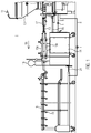
Ferner kann in der Linie auch ein Clipper 16 angeordnet sein, zum Setzen eines Klipps zwischen zwei Wurstportionen. Schließlich ist bei diesem speziellen Beispiel auch ein Hänger 18 angeordnet, der an seinen Haken 19 einzelne Würste oder Wurstportionen aufnehmen und weitertransportieren kann.Furthermore, a
Der in
Um den rauen Bedingungen bei der Lebensmittelproduktion Rechnung zu tragen, wird für eine entsprechende Füllmaschine bzw. eine entsprechende Fülllinie ein Verbindersystem zur Datenübertragung an einer Schnittstelle zwischen zwei Geräten vorgeschlagen, das wie folgt aufgebaut sein kann.In order to take account of the harsh conditions in food production, a connector system for data transmission at an interface between two devices is proposed for a corresponding filling machine or a corresponding filling line, which can be constructed as follows.
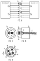
Bei der vorliegenden Erfindung weist der Verbinder 1, wie insbesondere aus
Die Verbindungselemente weisen Datenübertragungsteile 3a und 3b auf, wobei diese Datenübertragungsteile derart ausgebildet sind, dass im gekoppelten bzw. verbundenen Zustand des ersten und zweiten Verbindungselementes die Datenübertragungsteile 3a,b galvanisch getrennt (d.h. also kontaktlos) sind. Hier in diesem ersten Ausführungsbeispiel erfolgt die galvanische Trennung durch zwei voneinander elektrisch isolierte Wicklungen und die Datenübertragung erfolgt induktiv. Dabei weist das erste Verbindungselemente 2a als Datenübertragungsteil eine Primärspule 3a auf, die einen Kern 7a umfasst. Der Kern 7 ist gekrümmt und weist jeweils zwei Stirnseiten 9 auf, die einem gegenüberliegenden Verbindungselement zugewandt sein können. Das zweite Verbindungselement 2b weist eine entsprechende Sekundärspule 3b auf.The connecting elements have
Beim Zusammenfügen der Primär- und Sekundärspule, d.h. beim Koppeln des ersten und zweiten Verbindungselements, funktionieren die beiden Spulenhälften dann wie ein Netzwerkübertrager.When assembling the primary and secondary coils, i. when coupling the first and second connection elements, the two coil halves then function like a network transmitter.
Für die induktive Übertragung können dabei bestehende Ethernetstandards nach IEEE 802.3 genutzt werden. Die Erfindung beruht daher auf der Grundlage folgender Überlegung.For inductive transmission existing Ethernet standards according to IEEE 802.3 can be used. The invention is therefore based on the following consideration.
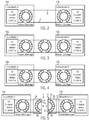
Wie in
Weil bei, insbesondere Ethernet-basierten, Übertragungsstrecken sowohl auf der Sender- als auch auf der Empfängerseite die Übertrager zur Potenzialtrennung verwendet werden, kann ohne weiteres noch ein zusätzlicher Übertrager in die Strecke eingefügt werden, wie in
Nach Zusammenfügen der Trennstelle wird das Magnetfeld wieder geschlossen und die Information kann ungehindert übertragen werden.After joining the separation point, the magnetic field is closed again and the information can be transmitted freely.
Das Datenübertragungsteil 3a,b kann also einfach erzeugt werden, indem ein herkömmlicher, beispielsweise dem Ethernetstandard genügender Übertrager in zwei Teile aufgetrennt wird oder ein Übertrager aus zwei Halbkernen zusammengefügt wird.The
Diese Datenübertragungsteile können dann in den jeweiligen Verbindungselementen 2a,b integriert werden. Die Primär- und Sekundärspule können dabei in ein Mantelmaterial, z. B. Kunstharz oder thermoplastische Kunststoffe eingegossen sein. Die Spulen werden komplett eingegossen, derart, dass auch eine dünne Schicht auf der Stirnfläche 9 der Kerne 7a,b ausgebildet ist. Diese Schicht sollte jedoch nicht dicker als 0,2 mm sein, um eine einwandfreie Datenübertragung zu gewährleisten. Es ist auch möglich, dass die Spulen 3a,b so eingegossen sind, dass die Stirnseiten 9 der Kerne 7a,b freiliegen. Dann können beim Verbinden der Verbindungselemente die Stirnseite der Kerne exakt aufeinandergebracht werden. Die Wicklungen der Spule sind dennoch ausreichend im geöffneten Zustand vor Feuchtigkeit und Schmutz geschützt. Es ist auch möglich, die freiliegenden Stirnseiten 9 der Kerne 7a,b durch eine dünne Beschichtung auf der Verbindervorderseite (die dem gegenüberliegenden Verbindungselement zugewandt ist) abzudichten. Als solche dünne Schicht kann beispielsweise eine Folie mit einer Dicke von 20 µm bis 300 µm verwendet werden. Die Spulen, d.h. die gewundenen Leitungsdrähte, sind auf jeden Fall hermetisch abgedichtet in den Verbindungselementen angeordnet.These data transmission parts can then be integrated in the respective connecting
Die Verbindungselemente 2a,b weisen eine mechanische Befestigungseinrichtung 4 auf, über die das erste Verbindungselement 2a mit dem zweiten Verbindungselement 2b gekoppelt werden kann, wie beispielsweise schematisch in
In den Funktionsskizzen in
Die mehreren Übertragerhälften bzw. Spulen werden, wie beispielsweise in
Die entsprechenden zweiten Verbindungselemente 2b sind dann so ausgebildet, dass die jeweiligen Stirnseiten 9 der einzelnen Kerne 7 bei Verbinden der Verbindungselemente 2a,b gegenüberliegen.The corresponding second connecting
Als Grundlage für den Verbinder wird beispielsweise ein Übertrager mit folgenden Kenndaten verwendet: Induktivität 350 µH bei 100 kHz, 100 mV AC, 8 mA DC, Windungsverhältnis 1:1.For example, a transformer with the following characteristics is used as the basis for the connector: Inductance 350 μH at 100 kHz, 100 mV AC, 8 mA DC, turn ratio 1: 1.
Bei solchen Übertragern sollte der Abstand a zwischen zwei Spulen, die im Wesentlichen in gleicher Richtung, also parallel zueinander ausgerichtet sind, in einem Bereich von 5 bis 10 mm liegen. Der Abstand b zwischen zwei Spulen, die im Wesentlichen senkrecht zueinander ausgerichtet sind, sollte in einem Bereich von 2 bis 5 mm liegen.In such transformers, the distance a between two coils, which are aligned in substantially the same direction, ie parallel to each other, should be in a range of 5 to 10 mm. The distance b between two coils that are substantially perpendicular to each other should be in a range of 2 to 5 mm.
Dieses Ausführungsbeispiel bringt den Vorteil mit sich, dass es nicht nötig ist, ein spezielles Protokoll einzusetzen, das Adressierung, Frequenzwechsel, Wiederholung oder Kollisionserkennung beherrscht. Es wird auch kein spezielles Modulationsverfahren benötigt. Eine Datenübertragung in Echtzeit ist möglich.This embodiment has the advantage that it is not necessary to use a special protocol that controls addressing, frequency change, repetition or collision detection. Also, no special modulation method is needed. Real-time data transmission is possible.
Im Zusammenhang mit den
Weil bei z.B. Ethernet-basierten Übertragungsstrecken die Informationen differenziell ohne Gleichspannungsbezug übertragen werden, können ohne weiteres Kondensatoren zur Leitungstrennung eingefügt werden.Because at e.g. Ethernet-based transmission links, the information can be transmitted differentially without reference to DC voltage, can be easily inserted capacitors for line separation.
Im Kondensator wird die Information durch ein elektrisches Feld weitergegeben. Ein Kondensator kann durch zwei elektrisch isolierte Elektroden hergestellt und so eine hermetisch dichte Trennstelle erzeugt werden. Durch Annäherung der beiden Elektroden wird das elektrische Feld geschlossen und die Information kann ungehindert übertragen werden, wie nachfolgend noch näher erläutert wird. Die Kondensatorelektroden können dabei jeweils vollständig in ein elektrisch isolierendes Mantelmaterial eingebettet, insbesondere eingegossen sein, wie beispielsweise in Kunstharz oder einem thermoplastischen Kunststoff.In the capacitor, the information is passed through an electric field. A capacitor can be made by two electrically insulated electrodes to create a hermetically sealed separation point. By approaching the two electrodes, the electric field is closed and the information can be transmitted freely, as will be explained in more detail below. The capacitor electrodes can each be completely embedded in an electrically insulating sheath material, in particular cast, such as in synthetic resin or a thermoplastic material.
Die
Die Kenngrößen des verwendeten Kondensators sind beispielsweise: C = 5 bis 50 nF.The characteristics of the capacitor used are, for example: C = 5 to 50 nF.
In den Funktionsskizzen 10 bis 13 wurde bisher immer nur ein Übertragungspfad gezeigt. Für eine Ethernetverbindung sind aber mindestens jeweils ein Sende- und ein Empfangskanal (bis 100 MBit/s) oder gar je zwei Sende- und Empfangskanäle nötig.
Als Gegenstück ist das Verbindungselement 2a vorgesehen, das als Hülse ausgebildet ist, derart, dass das Verbindungselement 2b zumindest teilweise in diese Hülse 2a eingeschoben werden kann, wobei der Durchmesser d2 größer als der Durchmesser d1 ist. An der inneren Oberfläche der Hülse sind ebenfalls ringförmige Kondensatorelektroden der Kondensatoren C1 bis C4 angebracht, wobei im gekoppelten Zustand der Verbindungselemente 2a,b die Elektroden der Hülse jeweils beabstandet gegenüberliegen. Der Verbinder weist eine mechanische Befestigungseinrichtung auf, die mit 5 angedeutet ist, beispielsweise eine Steckverbindung, über die die Hülse zum Zylinder ausgerichtet werden kann und über die eine hermetisch dichte Verbindung hergestellt werden kann. Die Kondensatorelektrodenoberflächen der Hülse können ebenfalls zum Schutz beschichtet sein, beispielsweise mit einer 50 µm bis 200 µm starken Folie oder Isolierschicht. Auch hier sind die Kabel 8 in die Verbindungselemente 2a,b eingegossen. Die Kapazität des Kondensators beträgt geeigneter weise 5 nF bis 50 nF.As a counterpart, the connecting
Wenn die Antennen eingegossen sind, sollte als Mantelmaterial ein thermoplastischer Kunststoff, wie z. B. Polyamid, Polyester oder Polyethylen verwendet werden. Aber auch Ein- oder Zweikomponenten-Vergussmasse, wie z. B. Epoxydharz, Polyesterharz, Vinylesterharz, Polyurethan, Silikonharz, Acrylharz, wahlweise mit Füllstoffen, wie z. B. Glasfaser, ist geeignet. Auch hier können die Kabel 8 in die Verbindungselemente eingegossen werden. Die Signalleitungen führen, wie aus der
Die in
Weiterhin ist auch eine Kombination aus herkömmlicher, kontaktbehafteter Übertragung und kontaktloser bzw. drahtloser Übertragung, wie im Zusammenhang mit den
Bei allen Ausführungsbeispielen können die Verbindungselemente über Kabel 8 mit den jeweiligen Geräten verbunden werden. Es ist jedoch auch möglich, dass eines der Verbindungselemente in einem Gerät integriert ist, an das dann das weitere Verbindungselement "angesteckt" wird.In all embodiments, the connecting elements can be connected via
Bei dem erfindungsgemäßen Verfahren, bei dem zwei Geräte zur Datenübertragung miteinander an einer bestimmten Schnittstelle verbunden werden sollen, werden zunächst das erste und zweite Verbindungselement 2a,b über die Befestigungseinrichtung 4 miteinander verbunden, z.B. ineinander gesteckt, verschraubt, etc. Dann kann eine Datenübertragung vom ersten zum zweiten Verbindungselement galvanisch getrennt erfolgen, d.h. kontakt- und drahtlos.In the method according to the invention, in which two devices for data transmission are to be connected to one another at a specific interface, first the first and
Claims (10)
- Filling line for sausage production with several apparatuses (10a, b), wherein at least two apparatuses of the filling line are connected with each other with a connector for real time processdata transmission wherein the first and second apparatus (10a, b) are at least two of the following group:filling machine, wring-off unit, clipper, hangup, separation element, conveying belt, handling apparatus, packing unit,and with a connector (1) comprising:a first connecting element (2a) which may be connected to the first apparatus (10a) and comprises at least one first data transmission part (3a), anda second connecting element (2b) that may be coupled to the first connecting element and connected to the second apparatus (10b) and comprises at least one second data transmission part (3b),wherein in the coupled state of the first and second connecting elements (2a, b), the first data transmission part (3a) is galvanically isolated from the second data transmission part (3b) and at least one of the connecting elements (2a, b) or both are connected with an apparatus (10a, b) via a cable (8).
- Filling line according to claim 1, characterized in that the connector (1) comprises a mechanical fixing device (4) which couples the first connecting element (2a) with the second connecting element (2b), in particular in a hermetically tight manner, the mechanical fixing device (4) in particular comprising a screw closure or a pin-and-socket connection or a bayonet catch or a clamped closure or a coupling by means of a permanent magnet.
- Filling line according to at least one of the preceding claims, characterized in that the first and second data transmission parts (3a, b) are disposed in the respective first and second connecting elements (2a, b) in a hermetically sealed manner.
- Filling line according to at least one of the preceding claims, characterized in that the first and second data transmission parts (3a, b) are cast into a casing material, in particular a thermoplastic or synthetic resin.
- Filling line according to at least one of the preceding claims, characterized in that the first connecting element (2a) as data transmission part (3a, b) comprises a primary coil (3a), and the second connecting element (2b) as data transmission part comprises a secondary coil (3b), such that the data are transmitted inductively.
- Filling line according to claim 5, characterized in that the primary coil (3a) and the secondary coil (3b) each corresponds to one half of a transformer (5) whose core, in particular annular core, is split, such that the respective front sides (6) of the split cores (7a, b) of the primary and secondary coils (3a, b) are oriented so as to face each other in the coupled state of the first and second connecting elements (2a, 2b).
- Filling line according to at least one of the preceding claims, characterized in that the first connecting element (2a) and the second connecting element (2b) are designed such that the data are transmitted capacitively, and wherein in particular the first connecting element as data transmission part comprises at least two first capacitor electrodes (3a), and the second connecting element as data transmission part comprises at least two second capacitor electrodes, the first and second capacitor electrodes facing each other in the coupled state of the connecting elements (2a, 2b).
- Filling line according to claim 7, characterized in that in the first connecting element (2a), several capacitor electrodes are disposed planely, in particular as plane rings on a support, in particular a cylinder, and the second connecting element is designed as a sleeve which comprises several plane capacitor electrodes, in particular embodied as plane rings, which, in the coupled state of the connecting elements (2a, b) are located opposite the first capacitor electrodes (3a).
- Filling line according to at least one of claims 1 to 8, characterized in that data transmission is effected via electromagnetic waves, and in particular either the first connecting element (2a) as data transmission part comprises a transmitting antenna (3a), and the second connecting element (2b) as data transmission part comprises a receiving antenna, or the first connecting element (2a) and the second connecting element (2b) as data transmission part comprise a combined transmitting and receiving antenna, or
an optocoupler is provided as transmitter and receiver. - Filling line according to at least one of claims 1 to 9, characterized in that the first and second connecting elements (2a, b) each comprise several data transmission parts (3a,b,c) for several transmission paths, in particular several coils, several capacitor electrodes, several transmitting and receiving antennae, optical transmitters and receivers.
Priority Applications (5)
| Application Number | Priority Date | Filing Date | Title |
|---|---|---|---|
| ES13167222.2T ES2588994T3 (en) | 2013-05-10 | 2013-05-10 | Connector between two devices for food manufacturing |
| EP13167222.2A EP2802085B1 (en) | 2013-05-10 | 2013-05-10 | Connector between two devices for food production |
| JP2014054893A JP5793791B2 (en) | 2013-05-10 | 2014-03-18 | Connector between two devices for food production |
| US14/228,516 US9419683B2 (en) | 2013-05-10 | 2014-03-28 | Connector between two apparatuses for food production |
| CN201410192626.7A CN104144004B (en) | 2013-05-10 | 2014-05-08 | Connector between two equipment of food production |
Applications Claiming Priority (1)
| Application Number | Priority Date | Filing Date | Title |
|---|---|---|---|
| EP13167222.2A EP2802085B1 (en) | 2013-05-10 | 2013-05-10 | Connector between two devices for food production |
Publications (2)
| Publication Number | Publication Date |
|---|---|
| EP2802085A1 EP2802085A1 (en) | 2014-11-12 |
| EP2802085B1 true EP2802085B1 (en) | 2016-08-10 |
Family
ID=48366208
Family Applications (1)
| Application Number | Title | Priority Date | Filing Date |
|---|---|---|---|
| EP13167222.2A Active EP2802085B1 (en) | 2013-05-10 | 2013-05-10 | Connector between two devices for food production |
Country Status (5)
| Country | Link |
|---|---|
| US (1) | US9419683B2 (en) |
| EP (1) | EP2802085B1 (en) |
| JP (1) | JP5793791B2 (en) |
| CN (1) | CN104144004B (en) |
| ES (1) | ES2588994T3 (en) |
Families Citing this family (1)
| Publication number | Priority date | Publication date | Assignee | Title |
|---|---|---|---|---|
| SK500072019A3 (en) * | 2019-02-27 | 2020-09-03 | Logomotion Sro | Antenna system with two solenoid antennas, mainly for NFC reception and transmission |
Citations (2)
| Publication number | Priority date | Publication date | Assignee | Title |
|---|---|---|---|---|
| US5572441A (en) * | 1994-04-04 | 1996-11-05 | Lucent Technologies Inc. | Data connector for portable devices |
| EP1312264A1 (en) * | 2001-11-19 | 2003-05-21 | Albert Handtmann Maschinenfabrik GmbH & Co. KG | Length measuring unit with clipping machine |
Family Cites Families (16)
| Publication number | Priority date | Publication date | Assignee | Title |
|---|---|---|---|---|
| JPS61174607A (en) * | 1985-01-28 | 1986-08-06 | Tetsuo Ishii | Electromagnetic inductive coupling type connector |
| JP3398880B2 (en) * | 1995-09-14 | 2003-04-21 | オムロン株式会社 | Wireless power transmission device |
| JP3169817B2 (en) * | 1996-01-30 | 2001-05-28 | 三菱電機株式会社 | Magnetic coupling signal transmission device |
| JP4280313B2 (en) * | 1997-10-16 | 2009-06-17 | 株式会社日立国際電気 | IC card system |
| US6932688B2 (en) * | 2001-10-12 | 2005-08-23 | Teepak Properties, Llc | Apparatus for automatically stuffing food casing |
| US8104165B1 (en) * | 2004-03-02 | 2012-01-31 | Motion Computing Inc. | Method of forming an apparatus used for reducing electromagnetic interference |
| EP1623628B1 (en) * | 2004-08-06 | 2008-09-10 | Albert Handtmann Maschinenfabrik GmbH & Co. KG | Method and device for detecting burst and/or depletion of a sausage casing during sausage production |
| ATE401225T1 (en) * | 2005-09-08 | 2008-08-15 | Voith Turbo Scharfenberg Gmbh | AUTOMATIC CENTER BUFFER COUPLING WITH AN ANTENNA FOR WIRELESS SIGNAL TRANSMISSION |
| EP1885085B1 (en) * | 2006-08-01 | 2013-03-06 | Siemens Aktiengesellschaft | Contactless means for supplying energy and data to bus users |
| JP4752718B2 (en) * | 2006-10-18 | 2011-08-17 | ソニー株式会社 | Communication system and communication apparatus |
| DE102007061610B4 (en) * | 2007-12-18 | 2010-01-14 | Phoenix Contact Gmbh & Co. Kg | Modular data transmission system with separate power supply for each connected module |
| US8212414B2 (en) * | 2008-07-10 | 2012-07-03 | Lockheed Martin Corporation | Resonant, contactless radio frequency power coupling |
| JP5433199B2 (en) * | 2008-10-21 | 2014-03-05 | 学校法人慶應義塾 | Electronic circuit |
| US9191263B2 (en) * | 2008-12-23 | 2015-11-17 | Keyssa, Inc. | Contactless replacement for cabled standards-based interfaces |
| WO2012172813A1 (en) * | 2011-06-14 | 2012-12-20 | パナソニック株式会社 | Communication device |
| CN102306890B (en) * | 2011-06-28 | 2014-03-26 | 东莞市日新传导科技股份有限公司 | High-frequency high-speed data connector |
-
2013
- 2013-05-10 ES ES13167222.2T patent/ES2588994T3/en active Active
- 2013-05-10 EP EP13167222.2A patent/EP2802085B1/en active Active
-
2014
- 2014-03-18 JP JP2014054893A patent/JP5793791B2/en active Active
- 2014-03-28 US US14/228,516 patent/US9419683B2/en active Active
- 2014-05-08 CN CN201410192626.7A patent/CN104144004B/en active Active
Patent Citations (2)
| Publication number | Priority date | Publication date | Assignee | Title |
|---|---|---|---|---|
| US5572441A (en) * | 1994-04-04 | 1996-11-05 | Lucent Technologies Inc. | Data connector for portable devices |
| EP1312264A1 (en) * | 2001-11-19 | 2003-05-21 | Albert Handtmann Maschinenfabrik GmbH & Co. KG | Length measuring unit with clipping machine |
Also Published As
| Publication number | Publication date |
|---|---|
| EP2802085A1 (en) | 2014-11-12 |
| US9419683B2 (en) | 2016-08-16 |
| CN104144004A (en) | 2014-11-12 |
| ES2588994T3 (en) | 2016-11-08 |
| CN104144004B (en) | 2017-07-21 |
| US20140333402A1 (en) | 2014-11-13 |
| JP2014225866A (en) | 2014-12-04 |
| JP5793791B2 (en) | 2015-10-14 |
Similar Documents
| Publication | Publication Date | Title |
|---|---|---|
| EP0980603B1 (en) | Plug-and-socket connection | |
| EP3195525B1 (en) | Input/output module for a bussystem | |
| DE112012003060B4 (en) | Power line communication system and transmitter | |
| EP2912778B1 (en) | Modular electronic system and bus subscriber | |
| EP3104469B1 (en) | Circular connector for data transmission of high data rates | |
| DE102012212254B3 (en) | Connector for cable-free signal transmission | |
| DE102017110956A1 (en) | Device for transmitting energy and information via a charging cable for an electric vehicle | |
| EP3207640A1 (en) | Plug connector for capacitively transmitting data | |
| EP2047571B1 (en) | Plug connector for telecommunications and data technology | |
| WO2018137991A1 (en) | Plug connector for connecting a waveguide to at least one electric conductor | |
| EP2673157B1 (en) | Apparatus for power transmission and for inductive communication | |
| EP2802085B1 (en) | Connector between two devices for food production | |
| EP2290877B1 (en) | Data bus connection assembly | |
| DE102010001484A1 (en) | Transmission device for use as e.g. data transmitter for contactless bidirectional transmission of data with sensor in transmission system, has compensating coil compensating influence of energy field provided on data coil | |
| EP2031626A1 (en) | Electrical low-voltage switching station | |
| EP1677588B1 (en) | Optical data transfer between mounting and feeding apparatus | |
| DE102012110170B4 (en) | Modular bus system for the transmission of data and / or energy | |
| DE3715594C2 (en) | Arrangement for connecting output and input stages of a transceiver | |
| DE102018120779B3 (en) | Contactless PoE connection system | |
| EP2665195B1 (en) | Device for providing an intrinsically safe supply voltage and for transmitting communication signals | |
| DE19606940B4 (en) | Asynchronous bus system with shared information and energy transfer based on a maximum of two-core cable | |
| EP0971238A2 (en) | Procedure and apparatus for directional fault-location or information transmission on low voltage networks in use | |
| EP4197432A1 (en) | Medical device with galvanic isolating device | |
| DE102011010793A1 (en) | Use of modem in communication device for inductive communication with track-guided or rail-guided movable object via untwisted symmetrical two wire line, using communication inductor connected with communication device | |
| DE202011002552U1 (en) | Using a modem |
Legal Events
| Date | Code | Title | Description |
|---|---|---|---|
| PUAI | Public reference made under article 153(3) epc to a published international application that has entered the european phase |
Free format text: ORIGINAL CODE: 0009012 |
|
| 17P | Request for examination filed |
Effective date: 20140211 |
|
| AK | Designated contracting states |
Kind code of ref document: A1 Designated state(s): AL AT BE BG CH CY CZ DE DK EE ES FI FR GB GR HR HU IE IS IT LI LT LU LV MC MK MT NL NO PL PT RO RS SE SI SK SM TR |
|
| AX | Request for extension of the european patent |
Extension state: BA ME |
|
| 17Q | First examination report despatched |
Effective date: 20151001 |
|
| GRAP | Despatch of communication of intention to grant a patent |
Free format text: ORIGINAL CODE: EPIDOSNIGR1 |
|
| INTG | Intention to grant announced |
Effective date: 20160329 |
|
| GRAS | Grant fee paid |
Free format text: ORIGINAL CODE: EPIDOSNIGR3 |
|
| GRAA | (expected) grant |
Free format text: ORIGINAL CODE: 0009210 |
|
| AK | Designated contracting states |
Kind code of ref document: B1 Designated state(s): AL AT BE BG CH CY CZ DE DK EE ES FI FR GB GR HR HU IE IS IT LI LT LU LV MC MK MT NL NO PL PT RO RS SE SI SK SM TR |
|
| REG | Reference to a national code |
Ref country code: GB Ref legal event code: FG4D Free format text: NOT ENGLISH |
|
| REG | Reference to a national code |
Ref country code: CH Ref legal event code: NV Representative=s name: PATENTANWALTSBUERO JEAN HUNZIKER AG, CH Ref country code: CH Ref legal event code: EP Ref country code: AT Ref legal event code: REF Ref document number: 819869 Country of ref document: AT Kind code of ref document: T Effective date: 20160815 |
|
| REG | Reference to a national code |
Ref country code: IE Ref legal event code: FG4D Free format text: LANGUAGE OF EP DOCUMENT: GERMAN |
|
| REG | Reference to a national code |
Ref country code: DE Ref legal event code: R096 Ref document number: 502013004000 Country of ref document: DE |
|
| REG | Reference to a national code |
Ref country code: NL Ref legal event code: FP |
|
| REG | Reference to a national code |
Ref country code: ES Ref legal event code: FG2A Ref document number: 2588994 Country of ref document: ES Kind code of ref document: T3 Effective date: 20161108 |
|
| REG | Reference to a national code |
Ref country code: LT Ref legal event code: MG4D |
|
| PG25 | Lapsed in a contracting state [announced via postgrant information from national office to epo] |
Ref country code: HR Free format text: LAPSE BECAUSE OF FAILURE TO SUBMIT A TRANSLATION OF THE DESCRIPTION OR TO PAY THE FEE WITHIN THE PRESCRIBED TIME-LIMIT Effective date: 20160810 Ref country code: IS Free format text: LAPSE BECAUSE OF FAILURE TO SUBMIT A TRANSLATION OF THE DESCRIPTION OR TO PAY THE FEE WITHIN THE PRESCRIBED TIME-LIMIT Effective date: 20161210 Ref country code: RS Free format text: LAPSE BECAUSE OF FAILURE TO SUBMIT A TRANSLATION OF THE DESCRIPTION OR TO PAY THE FEE WITHIN THE PRESCRIBED TIME-LIMIT Effective date: 20160810 Ref country code: LT Free format text: LAPSE BECAUSE OF FAILURE TO SUBMIT A TRANSLATION OF THE DESCRIPTION OR TO PAY THE FEE WITHIN THE PRESCRIBED TIME-LIMIT Effective date: 20160810 Ref country code: NO Free format text: LAPSE BECAUSE OF FAILURE TO SUBMIT A TRANSLATION OF THE DESCRIPTION OR TO PAY THE FEE WITHIN THE PRESCRIBED TIME-LIMIT Effective date: 20161110 Ref country code: FI Free format text: LAPSE BECAUSE OF FAILURE TO SUBMIT A TRANSLATION OF THE DESCRIPTION OR TO PAY THE FEE WITHIN THE PRESCRIBED TIME-LIMIT Effective date: 20160810 |
|
| PG25 | Lapsed in a contracting state [announced via postgrant information from national office to epo] |
Ref country code: PL Free format text: LAPSE BECAUSE OF FAILURE TO SUBMIT A TRANSLATION OF THE DESCRIPTION OR TO PAY THE FEE WITHIN THE PRESCRIBED TIME-LIMIT Effective date: 20160810 Ref country code: LV Free format text: LAPSE BECAUSE OF FAILURE TO SUBMIT A TRANSLATION OF THE DESCRIPTION OR TO PAY THE FEE WITHIN THE PRESCRIBED TIME-LIMIT Effective date: 20160810 Ref country code: PT Free format text: LAPSE BECAUSE OF FAILURE TO SUBMIT A TRANSLATION OF THE DESCRIPTION OR TO PAY THE FEE WITHIN THE PRESCRIBED TIME-LIMIT Effective date: 20161212 Ref country code: SE Free format text: LAPSE BECAUSE OF FAILURE TO SUBMIT A TRANSLATION OF THE DESCRIPTION OR TO PAY THE FEE WITHIN THE PRESCRIBED TIME-LIMIT Effective date: 20160810 Ref country code: GR Free format text: LAPSE BECAUSE OF FAILURE TO SUBMIT A TRANSLATION OF THE DESCRIPTION OR TO PAY THE FEE WITHIN THE PRESCRIBED TIME-LIMIT Effective date: 20161111 |
|
| PG25 | Lapsed in a contracting state [announced via postgrant information from national office to epo] |
Ref country code: EE Free format text: LAPSE BECAUSE OF FAILURE TO SUBMIT A TRANSLATION OF THE DESCRIPTION OR TO PAY THE FEE WITHIN THE PRESCRIBED TIME-LIMIT Effective date: 20160810 Ref country code: RO Free format text: LAPSE BECAUSE OF FAILURE TO SUBMIT A TRANSLATION OF THE DESCRIPTION OR TO PAY THE FEE WITHIN THE PRESCRIBED TIME-LIMIT Effective date: 20160810 |
|
| REG | Reference to a national code |
Ref country code: DE Ref legal event code: R097 Ref document number: 502013004000 Country of ref document: DE |
|
| PG25 | Lapsed in a contracting state [announced via postgrant information from national office to epo] |
Ref country code: DK Free format text: LAPSE BECAUSE OF FAILURE TO SUBMIT A TRANSLATION OF THE DESCRIPTION OR TO PAY THE FEE WITHIN THE PRESCRIBED TIME-LIMIT Effective date: 20160810 Ref country code: SM Free format text: LAPSE BECAUSE OF FAILURE TO SUBMIT A TRANSLATION OF THE DESCRIPTION OR TO PAY THE FEE WITHIN THE PRESCRIBED TIME-LIMIT Effective date: 20160810 Ref country code: SK Free format text: LAPSE BECAUSE OF FAILURE TO SUBMIT A TRANSLATION OF THE DESCRIPTION OR TO PAY THE FEE WITHIN THE PRESCRIBED TIME-LIMIT Effective date: 20160810 Ref country code: CZ Free format text: LAPSE BECAUSE OF FAILURE TO SUBMIT A TRANSLATION OF THE DESCRIPTION OR TO PAY THE FEE WITHIN THE PRESCRIBED TIME-LIMIT Effective date: 20160810 Ref country code: BG Free format text: LAPSE BECAUSE OF FAILURE TO SUBMIT A TRANSLATION OF THE DESCRIPTION OR TO PAY THE FEE WITHIN THE PRESCRIBED TIME-LIMIT Effective date: 20161110 |
|
| PLBE | No opposition filed within time limit |
Free format text: ORIGINAL CODE: 0009261 |
|
| STAA | Information on the status of an ep patent application or granted ep patent |
Free format text: STATUS: NO OPPOSITION FILED WITHIN TIME LIMIT |
|
| 26N | No opposition filed |
Effective date: 20170511 |
|
| PG25 | Lapsed in a contracting state [announced via postgrant information from national office to epo] |
Ref country code: LU Free format text: LAPSE BECAUSE OF NON-PAYMENT OF DUE FEES Effective date: 20170531 Ref country code: SI Free format text: LAPSE BECAUSE OF FAILURE TO SUBMIT A TRANSLATION OF THE DESCRIPTION OR TO PAY THE FEE WITHIN THE PRESCRIBED TIME-LIMIT Effective date: 20160810 |
|
| PG25 | Lapsed in a contracting state [announced via postgrant information from national office to epo] |
Ref country code: MC Free format text: LAPSE BECAUSE OF FAILURE TO SUBMIT A TRANSLATION OF THE DESCRIPTION OR TO PAY THE FEE WITHIN THE PRESCRIBED TIME-LIMIT Effective date: 20160810 |
|
| REG | Reference to a national code |
Ref country code: IE Ref legal event code: MM4A |
|
| REG | Reference to a national code |
Ref country code: FR Ref legal event code: ST Effective date: 20180131 |
|
| PG25 | Lapsed in a contracting state [announced via postgrant information from national office to epo] |
Ref country code: LU Free format text: LAPSE BECAUSE OF NON-PAYMENT OF DUE FEES Effective date: 20170510 |
|
| REG | Reference to a national code |
Ref country code: BE Ref legal event code: MM Effective date: 20170531 |
|
| PG25 | Lapsed in a contracting state [announced via postgrant information from national office to epo] |
Ref country code: IE Free format text: LAPSE BECAUSE OF NON-PAYMENT OF DUE FEES Effective date: 20170510 |
|
| PG25 | Lapsed in a contracting state [announced via postgrant information from national office to epo] |
Ref country code: FR Free format text: LAPSE BECAUSE OF NON-PAYMENT OF DUE FEES Effective date: 20170531 |
|
| PG25 | Lapsed in a contracting state [announced via postgrant information from national office to epo] |
Ref country code: BE Free format text: LAPSE BECAUSE OF NON-PAYMENT OF DUE FEES Effective date: 20170531 |
|
| PG25 | Lapsed in a contracting state [announced via postgrant information from national office to epo] |
Ref country code: MT Free format text: LAPSE BECAUSE OF FAILURE TO SUBMIT A TRANSLATION OF THE DESCRIPTION OR TO PAY THE FEE WITHIN THE PRESCRIBED TIME-LIMIT Effective date: 20160810 |
|
| PG25 | Lapsed in a contracting state [announced via postgrant information from national office to epo] |
Ref country code: AL Free format text: LAPSE BECAUSE OF FAILURE TO SUBMIT A TRANSLATION OF THE DESCRIPTION OR TO PAY THE FEE WITHIN THE PRESCRIBED TIME-LIMIT Effective date: 20160810 |
|
| PG25 | Lapsed in a contracting state [announced via postgrant information from national office to epo] |
Ref country code: HU Free format text: LAPSE BECAUSE OF FAILURE TO SUBMIT A TRANSLATION OF THE DESCRIPTION OR TO PAY THE FEE WITHIN THE PRESCRIBED TIME-LIMIT; INVALID AB INITIO Effective date: 20130510 |
|
| PG25 | Lapsed in a contracting state [announced via postgrant information from national office to epo] |
Ref country code: CY Free format text: LAPSE BECAUSE OF FAILURE TO SUBMIT A TRANSLATION OF THE DESCRIPTION OR TO PAY THE FEE WITHIN THE PRESCRIBED TIME-LIMIT Effective date: 20160810 |
|
| PG25 | Lapsed in a contracting state [announced via postgrant information from national office to epo] |
Ref country code: MK Free format text: LAPSE BECAUSE OF FAILURE TO SUBMIT A TRANSLATION OF THE DESCRIPTION OR TO PAY THE FEE WITHIN THE PRESCRIBED TIME-LIMIT Effective date: 20160810 |
|
| PG25 | Lapsed in a contracting state [announced via postgrant information from national office to epo] |
Ref country code: TR Free format text: LAPSE BECAUSE OF FAILURE TO SUBMIT A TRANSLATION OF THE DESCRIPTION OR TO PAY THE FEE WITHIN THE PRESCRIBED TIME-LIMIT Effective date: 20160810 |
|
| REG | Reference to a national code |
Ref country code: CH Ref legal event code: PFUS Owner name: ALBERT HANDTMANN MASCHINENFABRIK GMBH AND CO. , DE Free format text: FORMER OWNER: ALBERT HANDTMANN MASCHINENFABRIK GMBH AND CO. KG, DE |
|
| P01 | Opt-out of the competence of the unified patent court (upc) registered |
Effective date: 20230523 |
|
| PGFP | Annual fee paid to national office [announced via postgrant information from national office to epo] |
Ref country code: NL Payment date: 20230525 Year of fee payment: 11 Ref country code: IT Payment date: 20230529 Year of fee payment: 11 Ref country code: ES Payment date: 20230601 Year of fee payment: 11 Ref country code: DE Payment date: 20230526 Year of fee payment: 11 Ref country code: CH Payment date: 20230602 Year of fee payment: 11 |
|
| PGFP | Annual fee paid to national office [announced via postgrant information from national office to epo] |
Ref country code: AT Payment date: 20230524 Year of fee payment: 11 |
|
| PGFP | Annual fee paid to national office [announced via postgrant information from national office to epo] |
Ref country code: GB Payment date: 20230526 Year of fee payment: 11 |