EP2857743A1 - Sensor and fastener - Google Patents
Sensor and fastener Download PDFInfo
- Publication number
- EP2857743A1 EP2857743A1 EP20140186102 EP14186102A EP2857743A1 EP 2857743 A1 EP2857743 A1 EP 2857743A1 EP 20140186102 EP20140186102 EP 20140186102 EP 14186102 A EP14186102 A EP 14186102A EP 2857743 A1 EP2857743 A1 EP 2857743A1
- Authority
- EP
- European Patent Office
- Prior art keywords
- fastener
- subject
- disposed
- hole
- coupling portion
- Prior art date
- Legal status (The legal status is an assumption and is not a legal conclusion. Google has not performed a legal analysis and makes no representation as to the accuracy of the status listed.)
- Withdrawn
Links
- 230000008878 coupling Effects 0.000 claims abstract description 58
- 238000010168 coupling process Methods 0.000 claims abstract description 58
- 238000005859 coupling reaction Methods 0.000 claims abstract description 58
- 210000001061 forehead Anatomy 0.000 claims description 29
- 210000003128 head Anatomy 0.000 claims description 27
- 230000035807 sensation Effects 0.000 description 6
- 235000019615 sensations Nutrition 0.000 description 6
- 206010040007 Sense of oppression Diseases 0.000 description 4
- 239000004744 fabric Substances 0.000 description 4
- 239000000463 material Substances 0.000 description 3
- 238000002835 absorbance Methods 0.000 description 2
- 238000011109 contamination Methods 0.000 description 2
- 230000006870 function Effects 0.000 description 2
- 238000005259 measurement Methods 0.000 description 2
- 102000001554 Hemoglobins Human genes 0.000 description 1
- 108010054147 Hemoglobins Proteins 0.000 description 1
- 239000002390 adhesive tape Substances 0.000 description 1
- QVGXLLKOCUKJST-UHFFFAOYSA-N atomic oxygen Chemical compound [O] QVGXLLKOCUKJST-UHFFFAOYSA-N 0.000 description 1
- 239000008280 blood Substances 0.000 description 1
- 210000004369 blood Anatomy 0.000 description 1
- 239000010410 layer Substances 0.000 description 1
- 238000000034 method Methods 0.000 description 1
- 229910052760 oxygen Inorganic materials 0.000 description 1
- 239000001301 oxygen Substances 0.000 description 1
- 238000006213 oxygenation reaction Methods 0.000 description 1
- 230000010349 pulsation Effects 0.000 description 1
- 239000000523 sample Substances 0.000 description 1
- 239000013464 silicone adhesive Substances 0.000 description 1
Images


Classifications
-
- A—HUMAN NECESSITIES
- A61—MEDICAL OR VETERINARY SCIENCE; HYGIENE
- A61B—DIAGNOSIS; SURGERY; IDENTIFICATION
- A61B5/00—Measuring for diagnostic purposes; Identification of persons
- A61B5/68—Arrangements of detecting, measuring or recording means, e.g. sensors, in relation to patient
- A61B5/6801—Arrangements of detecting, measuring or recording means, e.g. sensors, in relation to patient specially adapted to be attached to or worn on the body surface
- A61B5/683—Means for maintaining contact with the body
- A61B5/6831—Straps, bands or harnesses
-
- A—HUMAN NECESSITIES
- A61—MEDICAL OR VETERINARY SCIENCE; HYGIENE
- A61B—DIAGNOSIS; SURGERY; IDENTIFICATION
- A61B5/00—Measuring for diagnostic purposes; Identification of persons
- A61B5/145—Measuring characteristics of blood in vivo, e.g. gas concentration, pH value; Measuring characteristics of body fluids or tissues, e.g. interstitial fluid, cerebral tissue
- A61B5/1455—Measuring characteristics of blood in vivo, e.g. gas concentration, pH value; Measuring characteristics of body fluids or tissues, e.g. interstitial fluid, cerebral tissue using optical sensors, e.g. spectral photometrical oximeters
- A61B5/14551—Measuring characteristics of blood in vivo, e.g. gas concentration, pH value; Measuring characteristics of body fluids or tissues, e.g. interstitial fluid, cerebral tissue using optical sensors, e.g. spectral photometrical oximeters for measuring blood gases
- A61B5/14552—Details of sensors specially adapted therefor
-
- A—HUMAN NECESSITIES
- A61—MEDICAL OR VETERINARY SCIENCE; HYGIENE
- A61B—DIAGNOSIS; SURGERY; IDENTIFICATION
- A61B5/00—Measuring for diagnostic purposes; Identification of persons
- A61B5/68—Arrangements of detecting, measuring or recording means, e.g. sensors, in relation to patient
- A61B5/6801—Arrangements of detecting, measuring or recording means, e.g. sensors, in relation to patient specially adapted to be attached to or worn on the body surface
- A61B5/6802—Sensor mounted on worn items
- A61B5/6803—Head-worn items, e.g. helmets, masks, headphones or goggles
-
- A—HUMAN NECESSITIES
- A61—MEDICAL OR VETERINARY SCIENCE; HYGIENE
- A61B—DIAGNOSIS; SURGERY; IDENTIFICATION
- A61B5/00—Measuring for diagnostic purposes; Identification of persons
- A61B5/68—Arrangements of detecting, measuring or recording means, e.g. sensors, in relation to patient
- A61B5/6801—Arrangements of detecting, measuring or recording means, e.g. sensors, in relation to patient specially adapted to be attached to or worn on the body surface
- A61B5/6813—Specially adapted to be attached to a specific body part
- A61B5/6814—Head
-
- A—HUMAN NECESSITIES
- A61—MEDICAL OR VETERINARY SCIENCE; HYGIENE
- A61B—DIAGNOSIS; SURGERY; IDENTIFICATION
- A61B5/00—Measuring for diagnostic purposes; Identification of persons
- A61B5/68—Arrangements of detecting, measuring or recording means, e.g. sensors, in relation to patient
- A61B5/6801—Arrangements of detecting, measuring or recording means, e.g. sensors, in relation to patient specially adapted to be attached to or worn on the body surface
- A61B5/6843—Monitoring or controlling sensor contact pressure
-
- A—HUMAN NECESSITIES
- A61—MEDICAL OR VETERINARY SCIENCE; HYGIENE
- A61B—DIAGNOSIS; SURGERY; IDENTIFICATION
- A61B2560/00—Constructional details of operational features of apparatus; Accessories for medical measuring apparatus
- A61B2560/04—Constructional details of apparatus
- A61B2560/0462—Apparatus with built-in sensors
-
- A—HUMAN NECESSITIES
- A61—MEDICAL OR VETERINARY SCIENCE; HYGIENE
- A61B—DIAGNOSIS; SURGERY; IDENTIFICATION
- A61B2562/00—Details of sensors; Constructional details of sensor housings or probes; Accessories for sensors
- A61B2562/14—Coupling media or elements to improve sensor contact with skin or tissue
-
- A—HUMAN NECESSITIES
- A61—MEDICAL OR VETERINARY SCIENCE; HYGIENE
- A61B—DIAGNOSIS; SURGERY; IDENTIFICATION
- A61B2562/00—Details of sensors; Constructional details of sensor housings or probes; Accessories for sensors
- A61B2562/22—Arrangements of medical sensors with cables or leads; Connectors or couplings specifically adapted for medical sensors
- A61B2562/225—Connectors or couplings
-
- A—HUMAN NECESSITIES
- A61—MEDICAL OR VETERINARY SCIENCE; HYGIENE
- A61B—DIAGNOSIS; SURGERY; IDENTIFICATION
- A61B5/00—Measuring for diagnostic purposes; Identification of persons
- A61B5/0059—Measuring for diagnostic purposes; Identification of persons using light, e.g. diagnosis by transillumination, diascopy, fluorescence
- A61B5/0082—Measuring for diagnostic purposes; Identification of persons using light, e.g. diagnosis by transillumination, diascopy, fluorescence adapted for particular medical purposes
-
- A—HUMAN NECESSITIES
- A61—MEDICAL OR VETERINARY SCIENCE; HYGIENE
- A61B—DIAGNOSIS; SURGERY; IDENTIFICATION
- A61B5/00—Measuring for diagnostic purposes; Identification of persons
- A61B5/02—Detecting, measuring or recording pulse, heart rate, blood pressure or blood flow; Combined pulse/heart-rate/blood pressure determination; Evaluating a cardiovascular condition not otherwise provided for, e.g. using combinations of techniques provided for in this group with electrocardiography or electroauscultation; Heart catheters for measuring blood pressure
- A61B5/021—Measuring pressure in heart or blood vessels
- A61B5/02108—Measuring pressure in heart or blood vessels from analysis of pulse wave characteristics
-
- A—HUMAN NECESSITIES
- A61—MEDICAL OR VETERINARY SCIENCE; HYGIENE
- A61B—DIAGNOSIS; SURGERY; IDENTIFICATION
- A61B5/00—Measuring for diagnostic purposes; Identification of persons
- A61B5/02—Detecting, measuring or recording pulse, heart rate, blood pressure or blood flow; Combined pulse/heart-rate/blood pressure determination; Evaluating a cardiovascular condition not otherwise provided for, e.g. using combinations of techniques provided for in this group with electrocardiography or electroauscultation; Heart catheters for measuring blood pressure
- A61B5/024—Detecting, measuring or recording pulse rate or heart rate
- A61B5/02416—Detecting, measuring or recording pulse rate or heart rate using photoplethysmograph signals, e.g. generated by infrared radiation
- A61B5/02427—Details of sensor
- A61B5/02433—Details of sensor for infrared radiation
-
- A—HUMAN NECESSITIES
- A61—MEDICAL OR VETERINARY SCIENCE; HYGIENE
- A61B—DIAGNOSIS; SURGERY; IDENTIFICATION
- A61B5/00—Measuring for diagnostic purposes; Identification of persons
- A61B5/02—Detecting, measuring or recording pulse, heart rate, blood pressure or blood flow; Combined pulse/heart-rate/blood pressure determination; Evaluating a cardiovascular condition not otherwise provided for, e.g. using combinations of techniques provided for in this group with electrocardiography or electroauscultation; Heart catheters for measuring blood pressure
- A61B5/024—Detecting, measuring or recording pulse rate or heart rate
- A61B5/02438—Detecting, measuring or recording pulse rate or heart rate with portable devices, e.g. worn by the patient
-
- A—HUMAN NECESSITIES
- A61—MEDICAL OR VETERINARY SCIENCE; HYGIENE
- A61B—DIAGNOSIS; SURGERY; IDENTIFICATION
- A61B5/00—Measuring for diagnostic purposes; Identification of persons
- A61B5/145—Measuring characteristics of blood in vivo, e.g. gas concentration, pH value; Measuring characteristics of body fluids or tissues, e.g. interstitial fluid, cerebral tissue
- A61B5/1455—Measuring characteristics of blood in vivo, e.g. gas concentration, pH value; Measuring characteristics of body fluids or tissues, e.g. interstitial fluid, cerebral tissue using optical sensors, e.g. spectral photometrical oximeters
- A61B5/14551—Measuring characteristics of blood in vivo, e.g. gas concentration, pH value; Measuring characteristics of body fluids or tissues, e.g. interstitial fluid, cerebral tissue using optical sensors, e.g. spectral photometrical oximeters for measuring blood gases
- A61B5/14553—Measuring characteristics of blood in vivo, e.g. gas concentration, pH value; Measuring characteristics of body fluids or tissues, e.g. interstitial fluid, cerebral tissue using optical sensors, e.g. spectral photometrical oximeters for measuring blood gases specially adapted for cerebral tissue
Definitions
- the presently disclosed subject matter relates to a sensor which is adapted to attach to the head of the subject to detect biological information, and also to a fastener which fastens the sensor to the head of the subject.
- Patent Literature 1 A sensor which is attached to the head of the subject to detect biological information is described in Patent Literature 1. Such a sensor is fastened to the head by a belt-like fastener in order to prevent dropping off from an attached portion (for example, see Patent Literature 2).
- the sensor disclosed in Patent Literature 1 includes a light emitter and a light detector.
- the light emitter and the light detector are placed on an attachment surface which is on the sensor body, and which is attached to the subject.
- the light emitter and the light detector are disposed so as to be projected from the attachment surface.
- the sensor body is attached to the head, therefore, the tip ends of the light emitter and the light detector butt against the skin, and the subject feels discomfort.
- the sensor body is pressed against the skin by a fastener such as that disclosed in Patent Literature 2.
- the subject feels pain in portions where the light emitter and the light detector butt against the skin.
- an object of the presently disclosed subject matter is to provide a technique for suppressing discomfort felt by the subject when a sensor is attached to the head.
- a first aspect of the presently disclosed subject matter is a sensor which is attached to a head of a subject.
- the sensor includes a first fastener that includes a first end portion and a second end portion and extends into an arc-shape, a first coupling portion that is disposed on an inner circumference side of the first fastener, a second fastener that includes a first side, a second side, a first through hole, and a second through hole, a second coupling portion that is disposed on the first side of the second fastener, and attachable to and detachable from the first coupling portion, a light emitter that is disposed on the first side of the second fastener, and opposed to the first through hole, and a light detector that is disposed on the first side of the second fastener, and opposed to the second through hole.
- the first fastener has an elasticity which allows a gap between the first end portion and the second end portion to be expanded.
- the first coupling portion is placed at a position which is opposed to a forehead of the subject when the sensor is attached to the head of the subject.
- the first end portion and the second end portion are placed on a back of the head of the subject when the sensor is attached to the head of the subject.
- a second aspect of the presently disclosed subject matter is a second fastener which fastens a light emitter and a light detector to a first fastener that is attached to a head of a subject.
- the second fastener includes a first side, a second side that is opposite to the first side, and opposed to the subject, a first through hole that communicates between the first side and the second side, a second through hole that communicates between the first side and the second side, and a second coupling portion that is disposed on the first side, and attachable to and detachable from a first coupling portion of the first fastener.
- the second coupling portion is coupled to the first coupling portion, the light emitter and the light detector are able to be disposed between the second fastener and the first fastener.
- the first and second end portions of the first fastener which extends in an arc-shape are separated from each other, and the first fastener has the elasticity which allows the gap between the end portions to be expanded.
- the light emitter and the light detector are held between the first and second fasteners by the coupling between the first and second coupling portions. Therefore, the sensor can be easily attached by one operation from the front side of the forehead of the subject. Even during sleeping of the subject, for example, the sensor can be attached to the subject without requiring a work of raising the head of the subject. Therefore, the workability is improved for the medical person, and troublesome for the subject in attachment of the sensor can be suppressed.
- the first fastener Since the light emitter and the light detector are held between the first and second fasteners, it is not necessary for the first fastener to generate a force for pressing the light emitter and the light detector against the forehead of the subject to hold them. It is sufficient for the first fastener to generate a force of a degree at which the second fastener is caused to be in close contact with the forehead of the subject to such an extent that the measurement using the light emitter and the light detector is enabled. Therefore, the second fastener is not pressed against the forehead more than necessary, and discomfort felt by the subject can be suppressed.
- the light emitter and the light detector are disposed between the first and second fasteners, and do not butt against the forehead of the subject.
- the second fastener which is larger in contact area than the light emitter and the light detector butts against the forehead, whereby the pressing force is dispersed, and discomfort felt by the subject can be suppressed.
- a configuration may be employed where the second side which is opposite to the first side has a first portion having a first elasticity, and a second portion having a second elasticity which is lower than the first elasticity, and the second portion extends through an area between the first through hole and the second through hole.
- the first portion when the sensor is attached to the forehead of the subject, the first portion is deformed in accordance with the shape of the forehead. Therefore, the adhesiveness of the second fastener to the forehead is enhanced, and a sense of oppression felt by the subject can be reduced.
- the amount of deformation of the second portion having the elasticity which is lower than the first elasticity is smaller than that of the first portion, and the second portion functions as a division wall between the first and second through holes. Therefore, a situation where a light beam which is emitted from the light emitter, and which passes through the first through hole enters toward the second through hole to be detected by the light detector, without being reflected from the forehead of the subject can be prevented from occurring. Namely, biological information of the subject can be correctly acquired while suppressing discomfort which is due to the sense of oppression, and which is felt by the subject.
- a configuration may be employed where the first side of the second fastener includes a first recess and a second recess.
- the light emitter is placed in the first recess
- the light detector is placed in the second recess.
- the light emitter and the light detector are surely positioned, so that the holdability is enhanced, and the thickness of the second fastener can be reduced. Therefore, an uncomfortable sensation due to the contacting of the second fastener in attachment of the sensor can be reduced, and discomfort felt by the subject can be suppressed.
- a configuration may be employed where the first fastener includes a mechanism to adjust a length in a longitudinal direction of the first fastener.
- the length in the longitudinal direction of the first fastener can be adjusted in accordance with the size of the head of the subject. Therefore, an uncomfortable sensation due to the attachment of the first fastener can be reduced according the subject, and hence discomfort felt by the subject during the attachment of the sensor can be suppressed.
- a configuration may be employed where the first fastener includes: a first cable holder which is disposed on a side of the first end portion with respect to a center portion in the longitudinal direction; and a second cable holder which is disposed on a side of the second end portion with respect to the center portion.
- the first cable holder and the second cable holder are configured so as to be able to hold cables connected to the light emitter and the light detector, respectively.
- the cables extending from the light emitter and light detector which are attached to the forehead are prevented from swinging in front of the eyes. Therefore, discomfort felt by the subject can be suppressed, and noise contamination in signals transmitted through the cables is prevented from occurring.
- at least one of the first and second cable holders can be used. Therefore, the cables can be held in a mode where the subject hardly feels an uncomfortable sensation.
- a configuration may be employed where the first coupling portion is a loop side of a hook and loop fastener, and the second coupling portion is a hook side of the hook and loop fastener.
- the first coupling portion is disposed on the side of the inner circumference of the first fastener. Therefore, the first coupling portion which is disposed in a place other than the place where the second coupling portion couples to the first coupling portion butts against the forehead of the subject.
- the loop side of a hook and loop fastener has soft texture. Therefore, discomfort felt by the subject can be suppressed.
- Fig. 1 is a perspective view illustrating a sensor 1 of an embodiment of the presently disclosed subject matter.
- the sensor 1 which is to be attached to the head of the subject can include a first fastener 10, a second fastener 20, a light emitter 30, and a light detector 40.
- the first fastener 10 can include a first end portion 11, a second end portion 12, and a body portion 13.
- the first end portion 11 is connected to a left end part of the body portion 13.
- the second end portion 12 is connected to a right end part of the body portion 13.
- the first fastener 10 extends in an arcuate shape as a whole, and the first end portion 11 and the second end portion 12 are separated from each other.
- the first fastener 10 has an elasticity which allows the gap between the first and second end portions 11, 12 to be expandingly opened.
- a first coupling portion 14 is disposed on the side of the inner circumference of the body portion 13.
- the first coupling portion 14 is the loop side of a hook and loop fastener.
- Cushion members 15 are disposed on the inner circumferential sides of the first and second end portions 11, 12, respectively.
- An example of the material of the cushion members 15 is a low elasticity sponge.
- the second fastener 20 has a first side which is opposed to the inner circumferential side of the first fastener 10, and a second side which is opposite to the first side.
- the second fastener 20 has first and second through holes 21, 22 communicating between the first side and the second side.
- Fig. 2A is a perspective view enlargedly illustrating the first side of the second fastener 20.
- a second coupling portion 23 is disposed on the first side.
- the second coupling portion 23 is the hook side of the hook and loop fastener, and attachable to and detachable from the first coupling portion 14 of the first fastener 10.
- Fig. 2B is a perspective view illustrating the light emitter 30 and the light detector 40.
- the light emitter 30 can include a light emitting portion 31, an attaching portion 32, and a signal line 33.
- the light detector 40 can include a light detecting portion 41, an attaching portion 42, and a signal line 43.
- the light emitting portion 31 emits light having a predetermined wavelength in accordance with a control signal which is input from a controller (not shown) through the signal line 33.
- the attaching portion 32 is disposed so as to surround the light emitting portion 31, and attachable to and detachable from the second coupling portion 23 of the second fastener 20.
- the attaching portion 32 may be configured by a rubber material, a towel cloth, a pile fabric, or the loop side of the hook and loop fastener.
- the light detecting portion 41 outputs a signal corresponding to the intensity of received light, through the signal line 43.
- the attaching portion 42 is disposed so as to surround the light detecting portion 41, and attachable to and detachable from the second coupling portion 23 of the second fastener 20.
- the attaching portion 42 may be configured by a rubber material, a towel cloth, a pile fabric, or the loop side of the hook and loop fastener.
- the light emitter 30 and the light detector 40 are placed on the first side of the second fastener 20. Specifically, they are placed so that the light emitting portion 31 of the light emitter 30 is opposed to the first through hole 21, and the light detecting portion 41 of the light detector 40 is opposed to the second through hole 22.
- the second fastener 20 is attached to the inner circumferential side of the body portion 13 of the first fastener 10.
- the first coupling portion 14 and the second coupling portion 23 are coupled to each other, and the light emitter 30 and the light detector 40 are disposed between the first fastener 10 and the second fastener 20.
- the place where the second fastener 20 is attached may be arbitrarily determined according to the subject, as far as the place is within the range where the first coupling portion 14 is disposed.
- Fig. 3A is a perspective view illustrating a state where the sensor having the above-described configuration is attached to the head of the subject
- Fig. 3B illustrates the state as viewed from above the head.
- the first coupling portion 14 of the first fastener 10 is placed at a position that is opposed to the forehead of the subject.
- the first end portion 11 and second end portion 12 of the first fastener 10 are placed on the back of the head of the subject.
- the light emitter 30 and the light detector 40 are used as a probe of a pulse oximeter.
- the light emitter is configured so as to emit a red light and an infrared light.
- the forehead of the subject is irradiated with the red and infrared light emitted from the light emitting portion 31 of the light emitter 30 through the first through hole 21 of the second fastener 20.
- the red and infrared light which are reflected from the forehead are detected by the light detecting portion 41 of the light detector 40 through the second through hole 22 of the second fastener 20.
- absorbance of a red light and absorbance of an infrared light are different depending on presence or absence of oxygenation.
- the first end portion 11 and second end portion of the first fastener 10 which arcuately extends are separated from each other, and the first fastener has an elasticity which allows the gap between the end portions to be expandingly opened.
- the light emitter 30 and the light detector 40 are held between the first and second fasteners 10, 20 by the coupling between the first and second coupling portions 14, 23. Therefore, the sensor 1 can be easily attached by one operation from the front side of the forehead of the subject. Even during sleeping of the subject, for example, the sensor 1 can be attached to the subject without requiring a work of raising the head of the subject. Therefore, the workability is improved for the medical person, and troublesome for the subject in the attachment of the sensor 1 can be suppressed.
- the first fastener 10 is not required to generate a force for pressing the light emitter 30 and the light detector 40 against the forehead of the subject to hold them. It is sufficient for the first fastener 10 to generate a force of a degree at which the second fastener 20 is caused to be in close contact with the forehead of the subject to such an extent that the measurement using the light emitter 30 and the light detector 40 is enabled.
- the configuration shown in Fig. 3B where the first end portion 11 and the second end portion go around to the back of the head of the subject cooperates with the elasticity of the first fastener 10 itself to enable generation of such a force. Therefore, the second fastener 20 is not pressed against the forehead more than necessary, and discomfort felt by the subject can be suppressed.
- the light emitter 30 and the light detector 40 are disposed between the first and second fasteners 10, 20, and do not butt against the forehead of the subject.
- the second fastener 20 which is larger in contact area than the light emitter 30 and the light detector 40 butts against the forehead, whereby the pressing force is dispersed, and discomfort felt by the subject can be suppressed.
- the second side of the second fastener 20 has a left contacting portion 24, a right contacting portion 25, and a center contacting portion 26.
- the left and right contacting portions 24, 25 are formed by, for example, a sponge, and have an elasticity.
- the center contacting portion 26 is formed by, for example, a low elastic sponge, and has an elasticity which is lower than that of the left and right contacting portions 24, 25.
- the first through hole 21 is opened in the left contacting portion 24, and the second through hole 22 is opened in the right contacting portion 25.
- the center contacting portion 26 extends so as to traverse the area between the first and second through holes 21, 22.
- the left and right contacting portions 24, 25 are deformed in accordance with the shape of the forehead. Therefore, the adhesiveness of the second fastener 20 to the forehead is enhanced, and a sense of oppression felt by the subject can be reduced.
- the amount of deformation of the center contacting portion 26 having the elasticity which is lower than the left and right contacting portions 24, 25 is smaller than the amounts of deformation of the left and right contacting portions 24, 25, and the center contacting portion functions as a division wall between the first and second through holes 21, 22.
- a first recess 27 and a second recess 28 are formed respectively in parts of the second coupling portion 23 which is disposed on the first side of the second fastener 20.
- the first through hole 21 is opened in the bottom of the first recess 27, and the second through hole 22 is opened in the bottom of the second recess 28.
- the shapes of the first and second recesses 27, 28 correspond to the attaching portion 32 of the light emitter 30 and the attaching portion 42 of the light detector 40, respectively.
- the attaching portion 32 is placed in the first recess 27, and the attaching portion 42 is placed in the second recess 28.
- the bottoms of the first and second recesses 27, 28 may be configured in an adequate mode as far as the attaching portion 32 of the light emitter 30 and the attaching portion 42 of the light detector 40 can be detachably coupled to the recesses.
- Each of the bottoms may be configured as the loop side of a hook and loop fastener in a similar manner as the second coupling portion 23, or an adhesive tape may be disposed.
- the light emitter 30 and the light detector 40 are surely positioned, so that the holdability is enhanced, and the thickness of the second fastener 20 can be reduced. Therefore, an uncomfortable sensation due to the contacting of the second fastener 20 in the attachment of the sensor 1 can be reduced, and discomfort felt by the subject can be suppressed.
- the second end portion 12 of the first fastener 10 is supported in a manner that it is slidable relative to the body portion 13.
- the first end portion 11 is similarly configured. Therefore, the length in the longitudinal direction of the first fastener 10 can be adjusted. In the attachment of the sensor 1, the sliding distance can be adjusted so that the first end portion 11 and the second end portion 12 are placed on the back of the head of the subject.
- the length in the longitudinal direction of the first fastener 10 can be adjusted in accordance with the size of the head of the subject. Therefore, an uncomfortable sensation due to the attachment of the first fastener 10 can be reduced according to the subject, and hence discomfort felt by the subject during the attachment of the sensor 1 can be suppressed.
- the first fastener 10 can include a first cable holder 16 and a second cable holder 17.
- the first cable holder 16 is disposed on the side of the first end portion 11 with respect to the center portion in the longitudinal direction of the first fastener 10.
- the second cable holder 17 is disposed on the side of the second end portion 12 with respect to the center portion in the longitudinal direction of the first fastener 10.
- the first cable holder 16 and the second cable holder 17 are configured so as to be able to hold signal lines 33, 43 (examples of the cables) connected to the light emitter 30 and the light detector 40, respectively. As shown in Fig. 3A , one of the first cable holder 16 and the second cable holder 17 may hold both the signal lines 33, 43, or the first cable holder 16 and the second cable holder 17 may hold the signal lines 33, 43, respectively (the reverse is also possible). In the embodiment, the first cable holder 16 and the second cable holder 17 are configured by a pair of belts which are attachable to and detachable from each other by means of a hook and loop fastener. Another holding structure may be employed as far as the signal lines 33, 43 can be held.
- the signal lines 33, 43 extending from the light emitter 30 and light detector 40 which are attached to the forehead are prevented from swinging in front of the eyes. Therefore, discomfort felt by the subject can be suppressed, and noise contamination in signals transmitted through the signal lines 33, 43 is prevented from occurring.
- at least one of the first and second cable holders 16, 17 can be used. Therefore, the cables can be held in a mode where the subject hardly feels an uncomfortable sensation.
- the loop side of a hook and loop fastener is used as the first coupling portion 14 of the first fastener 10
- the hook side of the hook and loop fastener is used as the second coupling portion 23 of the second fastener 20.
- the first coupling portion 14 is disposed on the side of the inner circumference of the first fastener 10. Therefore, the first coupling portion which is disposed in a place other than the place where the second coupling portion 23 couples to the first coupling portion butts against the forehead of the subject.
- the loop side of a hook and loop fastener has soft texture. Therefore, discomfort felt by the subject can be suppressed.
- the portions may have a configuration other than a hook and loop fastener.
- tape members in each of which the surface has a silicone adhesive layer having a re-adhesion property may be used as the first and second coupling portions 14, 23, respectively.
- the mechanism which enables the length in the longitudinal direction of the first fastener 10 to be adjusted is not limited to the sliding mechanism for the first and second end portions 11, 12. As far as the length in the longitudinal direction of the first fastener 10 can be adjusted, an adequate mechanism may be employed in at least one of the first and second end portions 11, 12 and the body portion 13.
Abstract
Description
- The presently disclosed subject matter relates to a sensor which is adapted to attach to the head of the subject to detect biological information, and also to a fastener which fastens the sensor to the head of the subject.
- A sensor which is attached to the head of the subject to detect biological information is described in Patent Literature 1. Such a sensor is fastened to the head by a belt-like fastener in order to prevent dropping off from an attached portion (for example, see Patent Literature 2).
- [Patent Literature 1]
JP-T-2005-505360 - [Patent Literature 2]
JP-T-2007-524482 - The sensor disclosed in Patent Literature 1 includes a light emitter and a light detector. The light emitter and the light detector are placed on an attachment surface which is on the sensor body, and which is attached to the subject. The light emitter and the light detector are disposed so as to be projected from the attachment surface. When the sensor body is attached to the head, therefore, the tip ends of the light emitter and the light detector butt against the skin, and the subject feels discomfort. Moreover, the sensor body is pressed against the skin by a fastener such as that disclosed in Patent Literature 2. When the examination is performed for a long time, therefore, the subject feels pain in portions where the light emitter and the light detector butt against the skin.
- Therefore, an object of the presently disclosed subject matter is to provide a technique for suppressing discomfort felt by the subject when a sensor is attached to the head.
- In order to attain the object, a first aspect of the presently disclosed subject matter is a sensor which is attached to a head of a subject. The sensor includes a first fastener that includes a first end portion and a second end portion and extends into an arc-shape, a first coupling portion that is disposed on an inner circumference side of the first fastener, a second fastener that includes a first side, a second side, a first through hole, and a second through hole, a second coupling portion that is disposed on the first side of the second fastener, and attachable to and detachable from the first coupling portion, a light emitter that is disposed on the first side of the second fastener, and opposed to the first through hole, and a light detector that is disposed on the first side of the second fastener, and opposed to the second through hole. The first fastener has an elasticity which allows a gap between the first end portion and the second end portion to be expanded. The first coupling portion is placed at a position which is opposed to a forehead of the subject when the sensor is attached to the head of the subject. The first end portion and the second end portion are placed on a back of the head of the subject when the sensor is attached to the head of the subject. When the first coupling portion and the second coupling portion are coupled to each other, the light emitter and the light detector are disposed between the first fastener and the second fastener.
- In order to attain the object, a second aspect of the presently disclosed subject matter is a second fastener which fastens a light emitter and a light detector to a first fastener that is attached to a head of a subject. The second fastener includes a first side, a second side that is opposite to the first side, and opposed to the subject, a first through hole that communicates between the first side and the second side, a second through hole that communicates between the first side and the second side, and a second coupling portion that is disposed on the first side, and attachable to and detachable from a first coupling portion of the first fastener. When the second coupling portion is coupled to the first coupling portion, the light emitter and the light detector are able to be disposed between the second fastener and the first fastener.
- According to the configuration, the first and second end portions of the first fastener which extends in an arc-shape are separated from each other, and the first fastener has the elasticity which allows the gap between the end portions to be expanded. The light emitter and the light detector are held between the first and second fasteners by the coupling between the first and second coupling portions. Therefore, the sensor can be easily attached by one operation from the front side of the forehead of the subject. Even during sleeping of the subject, for example, the sensor can be attached to the subject without requiring a work of raising the head of the subject. Therefore, the workability is improved for the medical person, and troublesome for the subject in attachment of the sensor can be suppressed.
- Since the light emitter and the light detector are held between the first and second fasteners, it is not necessary for the first fastener to generate a force for pressing the light emitter and the light detector against the forehead of the subject to hold them. It is sufficient for the first fastener to generate a force of a degree at which the second fastener is caused to be in close contact with the forehead of the subject to such an extent that the measurement using the light emitter and the light detector is enabled. Therefore, the second fastener is not pressed against the forehead more than necessary, and discomfort felt by the subject can be suppressed.
- At this time, the light emitter and the light detector are disposed between the first and second fasteners, and do not butt against the forehead of the subject. The second fastener which is larger in contact area than the light emitter and the light detector butts against the forehead, whereby the pressing force is dispersed, and discomfort felt by the subject can be suppressed.
- A configuration may be employed where the second side which is opposite to the first side has a first portion having a first elasticity, and a second portion having a second elasticity which is lower than the first elasticity, and the second portion extends through an area between the first through hole and the second through hole.
- According to the configuration, when the sensor is attached to the forehead of the subject, the first portion is deformed in accordance with the shape of the forehead. Therefore, the adhesiveness of the second fastener to the forehead is enhanced, and a sense of oppression felt by the subject can be reduced. At this time, the amount of deformation of the second portion having the elasticity which is lower than the first elasticity is smaller than that of the first portion, and the second portion functions as a division wall between the first and second through holes. Therefore, a situation where a light beam which is emitted from the light emitter, and which passes through the first through hole enters toward the second through hole to be detected by the light detector, without being reflected from the forehead of the subject can be prevented from occurring. Namely, biological information of the subject can be correctly acquired while suppressing discomfort which is due to the sense of oppression, and which is felt by the subject.
- A configuration may be employed where the first side of the second fastener includes a first recess and a second recess. In this case, the light emitter is placed in the first recess, and the light detector is placed in the second recess.
- According to the configuration, the light emitter and the light detector are surely positioned, so that the holdability is enhanced, and the thickness of the second fastener can be reduced. Therefore, an uncomfortable sensation due to the contacting of the second fastener in attachment of the sensor can be reduced, and discomfort felt by the subject can be suppressed.
- A configuration may be employed where the first fastener includes a mechanism to adjust a length in a longitudinal direction of the first fastener.
- According to the configuration, the length in the longitudinal direction of the first fastener can be adjusted in accordance with the size of the head of the subject. Therefore, an uncomfortable sensation due to the attachment of the first fastener can be reduced according the subject, and hence discomfort felt by the subject during the attachment of the sensor can be suppressed.
- A configuration may be employed where the first fastener includes: a first cable holder which is disposed on a side of the first end portion with respect to a center portion in the longitudinal direction; and a second cable holder which is disposed on a side of the second end portion with respect to the center portion. In this case, the first cable holder and the second cable holder are configured so as to be able to hold cables connected to the light emitter and the light detector, respectively.
- According to the configuration, the cables extending from the light emitter and light detector which are attached to the forehead are prevented from swinging in front of the eyes. Therefore, discomfort felt by the subject can be suppressed, and noise contamination in signals transmitted through the cables is prevented from occurring. According to the taste of the subject, or examination conditions, at least one of the first and second cable holders can be used. Therefore, the cables can be held in a mode where the subject hardly feels an uncomfortable sensation.
- A configuration may be employed where the first coupling portion is a loop side of a hook and loop fastener, and the second coupling portion is a hook side of the hook and loop fastener.
- The first coupling portion is disposed on the side of the inner circumference of the first fastener. Therefore, the first coupling portion which is disposed in a place other than the place where the second coupling portion couples to the first coupling portion butts against the forehead of the subject. However, the loop side of a hook and loop fastener has soft texture. Therefore, discomfort felt by the subject can be suppressed.
-
-
Fig. 1 is a perspective view illustrating a sensor of an embodiment of the presently disclosed subject matter. -
Figs. 2A to 2C illustrate the configuration of a first side of a second fastener of the sensor ofFig. 1 . -
Figs. 3A and 3B illustrate a state where the sensor ofFig. 1 is attached to the head of the subject. -
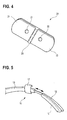
Fig. 4 illustrates the configuration of a second side of the second fastener of the sensor ofFig. 1 . -
Fig. 5 is a perspective view illustrating the configuration of an end portion of a first fastener of the sensor ofFig. 1 . - Hereinafter, an embodiment of the presently disclosed subject matter will be described in detail with reference to the accompanying drawings. In the drawings which will be used in the following description, the scale is adequately changed in order to draw components in a recognizable size.
-
Fig. 1 is a perspective view illustrating a sensor 1 of an embodiment of the presently disclosed subject matter. The sensor 1 which is to be attached to the head of the subject can include afirst fastener 10, asecond fastener 20, alight emitter 30, and alight detector 40. - The
first fastener 10 can include afirst end portion 11, asecond end portion 12, and abody portion 13. Thefirst end portion 11 is connected to a left end part of thebody portion 13. Thesecond end portion 12 is connected to a right end part of thebody portion 13. - The
first fastener 10 extends in an arcuate shape as a whole, and thefirst end portion 11 and thesecond end portion 12 are separated from each other. Thefirst fastener 10 has an elasticity which allows the gap between the first andsecond end portions - A
first coupling portion 14 is disposed on the side of the inner circumference of thebody portion 13. For example, thefirst coupling portion 14 is the loop side of a hook and loop fastener.Cushion members 15 are disposed on the inner circumferential sides of the first andsecond end portions cushion members 15 is a low elasticity sponge. - The
second fastener 20 has a first side which is opposed to the inner circumferential side of thefirst fastener 10, and a second side which is opposite to the first side. Thesecond fastener 20 has first and second throughholes -
Fig. 2A is a perspective view enlargedly illustrating the first side of thesecond fastener 20. Asecond coupling portion 23 is disposed on the first side. For example, thesecond coupling portion 23 is the hook side of the hook and loop fastener, and attachable to and detachable from thefirst coupling portion 14 of thefirst fastener 10. -
Fig. 2B is a perspective view illustrating thelight emitter 30 and thelight detector 40. Thelight emitter 30 can include alight emitting portion 31, an attachingportion 32, and asignal line 33. Thelight detector 40 can include alight detecting portion 41, an attachingportion 42, and asignal line 43. - The
light emitting portion 31 emits light having a predetermined wavelength in accordance with a control signal which is input from a controller (not shown) through thesignal line 33. The attachingportion 32 is disposed so as to surround thelight emitting portion 31, and attachable to and detachable from thesecond coupling portion 23 of thesecond fastener 20. For example, the attachingportion 32 may be configured by a rubber material, a towel cloth, a pile fabric, or the loop side of the hook and loop fastener. - The
light detecting portion 41 outputs a signal corresponding to the intensity of received light, through thesignal line 43. The attachingportion 42 is disposed so as to surround thelight detecting portion 41, and attachable to and detachable from thesecond coupling portion 23 of thesecond fastener 20. For example, the attachingportion 42 may be configured by a rubber material, a towel cloth, a pile fabric, or the loop side of the hook and loop fastener. - As shown in
Fig. 2C , thelight emitter 30 and thelight detector 40 are placed on the first side of thesecond fastener 20. Specifically, they are placed so that thelight emitting portion 31 of thelight emitter 30 is opposed to the first throughhole 21, and thelight detecting portion 41 of thelight detector 40 is opposed to the second throughhole 22. - As shown in
Fig. 1 , thesecond fastener 20 is attached to the inner circumferential side of thebody portion 13 of thefirst fastener 10. At this time, thefirst coupling portion 14 and thesecond coupling portion 23 are coupled to each other, and thelight emitter 30 and thelight detector 40 are disposed between thefirst fastener 10 and thesecond fastener 20. The place where thesecond fastener 20 is attached may be arbitrarily determined according to the subject, as far as the place is within the range where thefirst coupling portion 14 is disposed. -
Fig. 3A is a perspective view illustrating a state where the sensor having the above-described configuration is attached to the head of the subject, andFig. 3B illustrates the state as viewed from above the head. In the attachment of the sensor 1, thefirst coupling portion 14 of thefirst fastener 10 is placed at a position that is opposed to the forehead of the subject. In the attachment of the sensor 1, moreover, thefirst end portion 11 andsecond end portion 12 of thefirst fastener 10 are placed on the back of the head of the subject. - For example, the
light emitter 30 and thelight detector 40 are used as a probe of a pulse oximeter. In this case, the light emitter is configured so as to emit a red light and an infrared light. The forehead of the subject is irradiated with the red and infrared light emitted from thelight emitting portion 31 of thelight emitter 30 through the first throughhole 21 of thesecond fastener 20. The red and infrared light which are reflected from the forehead are detected by thelight detecting portion 41 of thelight detector 40 through the second throughhole 22 of thesecond fastener 20. In hemoglobin in blood, absorbance of a red light and absorbance of an infrared light are different depending on presence or absence of oxygenation. When the intensities of the red light and the infrared light detected by thelight detector 41 are analyzed, therefore, it is possible to measure the arterial oxygen saturation (SpO2). When the pulse wave component due to the pulsation of the heart is detected, it is possible to measure the pulse rate. - In the thus configured sensor 1, the
first end portion 11 and second end portion of thefirst fastener 10 which arcuately extends are separated from each other, and the first fastener has an elasticity which allows the gap between the end portions to be expandingly opened. Thelight emitter 30 and thelight detector 40 are held between the first andsecond fasteners second coupling portions - Since the
light emitter 30 and thelight detector 40 are held between the first andsecond fasteners first fastener 10 is not required to generate a force for pressing thelight emitter 30 and thelight detector 40 against the forehead of the subject to hold them. It is sufficient for thefirst fastener 10 to generate a force of a degree at which thesecond fastener 20 is caused to be in close contact with the forehead of the subject to such an extent that the measurement using thelight emitter 30 and thelight detector 40 is enabled. In the attachment of the sensor 1, the configuration shown inFig. 3B where thefirst end portion 11 and the second end portion go around to the back of the head of the subject cooperates with the elasticity of thefirst fastener 10 itself to enable generation of such a force. Therefore, thesecond fastener 20 is not pressed against the forehead more than necessary, and discomfort felt by the subject can be suppressed. - At this time, the
light emitter 30 and thelight detector 40 are disposed between the first andsecond fasteners second fastener 20 which is larger in contact area than thelight emitter 30 and thelight detector 40 butts against the forehead, whereby the pressing force is dispersed, and discomfort felt by the subject can be suppressed. - As shown in
Fig. 4 , the second side of thesecond fastener 20 has a left contactingportion 24, aright contacting portion 25, and acenter contacting portion 26. The left and right contactingportions 24, 25 (an example of the first portion) are formed by, for example, a sponge, and have an elasticity. The center contacting portion 26 (an example of the second portion) is formed by, for example, a low elastic sponge, and has an elasticity which is lower than that of the left and right contactingportions - The first through
hole 21 is opened in theleft contacting portion 24, and the second throughhole 22 is opened in theright contacting portion 25. Thecenter contacting portion 26 extends so as to traverse the area between the first and second throughholes - According to the configuration, when the sensor 1 is attached to the forehead of the subject, the left and right contacting
portions second fastener 20 to the forehead is enhanced, and a sense of oppression felt by the subject can be reduced. At this time, the amount of deformation of thecenter contacting portion 26 having the elasticity which is lower than the left and right contactingportions portions holes light emitter 30 passes through the first throughhole 21 enters toward the second throughhole 22 to be detected by thelight detector 40, without being reflected from the forehead of the subject can be prevented from occurring. Namely, biological information of the subject can be correctly acquired while suppressing discomfort which is due to the sense of oppression, and which is felt by the subject. - As shown in
Fig. 2A , afirst recess 27 and asecond recess 28 are formed respectively in parts of thesecond coupling portion 23 which is disposed on the first side of thesecond fastener 20. The first throughhole 21 is opened in the bottom of thefirst recess 27, and the second throughhole 22 is opened in the bottom of thesecond recess 28. The shapes of the first andsecond recesses portion 32 of thelight emitter 30 and the attachingportion 42 of thelight detector 40, respectively. In the state shown inFig. 2C where thelight emitter 30 and thelight detector 40 are attached, the attachingportion 32 is placed in thefirst recess 27, and the attachingportion 42 is placed in thesecond recess 28. - The bottoms of the first and
second recesses portion 32 of thelight emitter 30 and the attachingportion 42 of thelight detector 40 can be detachably coupled to the recesses. Each of the bottoms may be configured as the loop side of a hook and loop fastener in a similar manner as thesecond coupling portion 23, or an adhesive tape may be disposed. - According to the configuration, the
light emitter 30 and thelight detector 40 are surely positioned, so that the holdability is enhanced, and the thickness of thesecond fastener 20 can be reduced. Therefore, an uncomfortable sensation due to the contacting of thesecond fastener 20 in the attachment of the sensor 1 can be reduced, and discomfort felt by the subject can be suppressed. - As shown in
Fig. 5 , thesecond end portion 12 of thefirst fastener 10 is supported in a manner that it is slidable relative to thebody portion 13. Although not illustrated, also thefirst end portion 11 is similarly configured. Therefore, the length in the longitudinal direction of thefirst fastener 10 can be adjusted. In the attachment of the sensor 1, the sliding distance can be adjusted so that thefirst end portion 11 and thesecond end portion 12 are placed on the back of the head of the subject. - According to the configuration, the length in the longitudinal direction of the
first fastener 10 can be adjusted in accordance with the size of the head of the subject. Therefore, an uncomfortable sensation due to the attachment of thefirst fastener 10 can be reduced according to the subject, and hence discomfort felt by the subject during the attachment of the sensor 1 can be suppressed. - As shown in
Fig. 1 , thefirst fastener 10 can include afirst cable holder 16 and asecond cable holder 17. Thefirst cable holder 16 is disposed on the side of thefirst end portion 11 with respect to the center portion in the longitudinal direction of thefirst fastener 10. Thesecond cable holder 17 is disposed on the side of thesecond end portion 12 with respect to the center portion in the longitudinal direction of thefirst fastener 10. - The
first cable holder 16 and thesecond cable holder 17 are configured so as to be able to holdsignal lines 33, 43 (examples of the cables) connected to thelight emitter 30 and thelight detector 40, respectively. As shown inFig. 3A , one of thefirst cable holder 16 and thesecond cable holder 17 may hold both the signal lines 33, 43, or thefirst cable holder 16 and thesecond cable holder 17 may hold the signal lines 33, 43, respectively (the reverse is also possible). In the embodiment, thefirst cable holder 16 and thesecond cable holder 17 are configured by a pair of belts which are attachable to and detachable from each other by means of a hook and loop fastener. Another holding structure may be employed as far as the signal lines 33, 43 can be held. - According to the configuration, the signal lines 33, 43 extending from the
light emitter 30 andlight detector 40 which are attached to the forehead are prevented from swinging in front of the eyes. Therefore, discomfort felt by the subject can be suppressed, and noise contamination in signals transmitted through the signal lines 33, 43 is prevented from occurring. According to the taste of the subject, or examination conditions, at least one of the first andsecond cable holders - The embodiment has been described in order to facilitate understanding of the presently disclosed subject matter, and is not intended to limit the presently disclosed subject matter. It is a matter of course that the presently disclosed subject matter may be changed or improved without departing the spirit thereof, and includes equivalent embodiments.
- In the embodiment, the loop side of a hook and loop fastener is used as the
first coupling portion 14 of thefirst fastener 10, and the hook side of the hook and loop fastener is used as thesecond coupling portion 23 of thesecond fastener 20. - The
first coupling portion 14 is disposed on the side of the inner circumference of thefirst fastener 10. Therefore, the first coupling portion which is disposed in a place other than the place where thesecond coupling portion 23 couples to the first coupling portion butts against the forehead of the subject. However, the loop side of a hook and loop fastener has soft texture. Therefore, discomfort felt by the subject can be suppressed. - As far as the first and
second coupling portions second coupling portions - The mechanism which enables the length in the longitudinal direction of the
first fastener 10 to be adjusted is not limited to the sliding mechanism for the first andsecond end portions first fastener 10 can be adjusted, an adequate mechanism may be employed in at least one of the first andsecond end portions body portion 13. - 1: sensor
- 10: first fastener
- 11: first end portion
- 12: second end portion
- 14: first coupling portion
- 16: first cable holder
- 17: second cable holder
- 20: second fastener
- 21: first through hole
- 22: second through hole
- 23: second coupling portion
- 24: left contacting portion
- 25: right contacting portion
- 26: center contacting portion
- 27: first recess
- 28: second recess
- 30: light emitter
- 40: light detector
Claims (9)
- A sensor which is adapted to attach to a head of a subject comprising:a first fastener that includes a first end portion and a second end portion and extends into an arc-shape;a first coupling portion that is disposed on an inner circumference side of the first fastener;a second fastener that includes a first side and a second side, and a first through hole and a second through hole;a second coupling portion that is disposed on the first side of the second fastener, and attachable to and detachable from the first coupling portion;a light emitter that is disposed on the first side of the second fastener, and opposed to the first through hole; anda light detector that is disposed on the first side of the second fastener, and opposed to the second through hole,wherein the first fastener has an elasticity which allows a gap between the first end portion and the second end portion to be expanded,the first coupling portion is placed at a position which is opposed to a forehead of the subject when the sensor is attached to the head of the subject,the first end portion and the second end portion are placed on a back of the head of the subject when the sensor is attached to the head of the subject, and,when the first coupling portion and the second coupling portion are coupled to each other, the light emitter and the light detector are disposed between the first fastener and the second fastener.
- The sensor according to claim 1, wherein
the second side which is opposite to the first side has a first portion having a first elasticity, and a second portion having a second elasticity which is lower than the first elasticity, and
the second portion extends through an area between the first through hole and the second through hole. - The sensor according to claim 1 or 2, wherein
the first side of the second fastener includes a first recess and a second recess,
the light emitter is placed in the first recess, and the light detector is placed in the second recess. - The sensor according to any one of claims 1 to 3, wherein the first fastener includes a mechanism to adjust a length in a longitudinal direction of the first fastener.
- The sensor according to any one of claims 1 to 4, wherein the first fastener includes:a first cable holder which is disposed on a side of the first end portion with respect to a center portion in the longitudinal direction; anda second cable holder which is disposed on a side of the second end portion with respect to the center portion, andthe first cable holder and the second cable holder are configured so as to be able to hold cables connected to the light emitter and the light detector, respectively.
- The sensor according to any one of claims 1 to 5, wherein the first coupling portion is a loop side of a hook and loop fastener, and
the second coupling portion is a hook side of the hook and loop fastener. - A second fastener which fastens a light emitter and a light detector to a first fastener that is adapted to attach to a head of a subject, comprising:a first side;a second side that is opposite to the first side, and opposed to the subject;a first through hole that communicates between the first side and the second side;a second through hole that communicates between the first side and the second side; anda second coupling portion that is disposed on the first side, and attachable to and detachable from a first coupling portion of the first fastener, and,when the second coupling portion is coupled to the first coupling portion, the light emitter and the light detector are able to be disposed between the second fastener and the first fastener.
- The second fastener according to claim 7, wherein
the second side has a first portion having a first elasticity, and a second portion having a second elasticity which is lower than the first elasticity, and
the second portion extends through an area between the first through hole and the second through hole. - The second fastener according to claim 7 or 8, wherein the second fastener further includes:a first recess that is formed in the first side, and able to hold the light emitter; anda second recess that is formed in the first side, and able to hold the light detector.
Applications Claiming Priority (1)
| Application Number | Priority Date | Filing Date | Title |
|---|---|---|---|
| JP2013209470A JP6189701B2 (en) | 2013-10-04 | 2013-10-04 | Sensor and fixture |
Publications (1)
| Publication Number | Publication Date |
|---|---|
| EP2857743A1 true EP2857743A1 (en) | 2015-04-08 |
Family
ID=51726299
Family Applications (1)
| Application Number | Title | Priority Date | Filing Date |
|---|---|---|---|
| EP20140186102 Withdrawn EP2857743A1 (en) | 2013-10-04 | 2014-09-24 | Sensor and fastener |
Country Status (4)
| Country | Link |
|---|---|
| US (1) | US9770198B2 (en) |
| EP (1) | EP2857743A1 (en) |
| JP (1) | JP6189701B2 (en) |
| CN (1) | CN104510477A (en) |
Families Citing this family (7)
| Publication number | Priority date | Publication date | Assignee | Title |
|---|---|---|---|---|
| JP6524867B2 (en) | 2015-09-02 | 2019-06-05 | トヨタ自動車株式会社 | Neck band type biological information detector |
| CN105411601A (en) * | 2015-12-31 | 2016-03-23 | 北京怡和嘉业医疗科技有限公司 | Blood oxygen monitoring device and breathing mask |
| US20180360382A1 (en) * | 2017-06-18 | 2018-12-20 | Pixart Imaging Inc. | Optical measurement device with pressure feedback function |
| JP2021013403A (en) * | 2017-10-20 | 2021-02-12 | アルプスアルパイン株式会社 | Biological information measuring apparatus, information processing apparatus, biological information measuring method, and program |
| JP2019089572A (en) * | 2017-11-13 | 2019-06-13 | ワールドウォーターバッグ株式会社 | Fluid storage bag |
| USD907221S1 (en) * | 2019-02-28 | 2021-01-05 | Helius Medical, Inc | Non-invasive neurostimulation device |
| USD916300S1 (en) * | 2019-02-28 | 2021-04-13 | Helius Medical, Inc | Non-invasive neurostimulation device |
Citations (6)
| Publication number | Priority date | Publication date | Assignee | Title |
|---|---|---|---|---|
| JP2005505360A (en) | 2001-10-12 | 2005-02-24 | ネルコアー ピューリタン ベネット インコーポレイテッド | Laminated adhesive optical sensor |
| JP2007524482A (en) | 2004-02-13 | 2007-08-30 | ネルコアー ピューリタン ベネット インコーポレイテッド | Headband with tension indicator |
| US20090105605A1 (en) * | 2003-04-22 | 2009-04-23 | Marcio Marc Abreu | Apparatus and method for measuring biologic parameters |
| US20090108205A1 (en) * | 2007-10-10 | 2009-04-30 | Cas Medical Systems, Inc. | Nirs sensor mounting apparatus |
| CN101461704A (en) * | 2007-12-21 | 2009-06-24 | 深圳迈瑞生物医疗电子股份有限公司 | Forehead sensor, bandage and forehead sensor fixing component |
| US20120083673A1 (en) * | 2010-09-28 | 2012-04-05 | Ammar Al-Ali | Depth of consciousness monitor including oximeter |
Family Cites Families (15)
| Publication number | Priority date | Publication date | Assignee | Title |
|---|---|---|---|---|
| US4938218A (en) * | 1983-08-30 | 1990-07-03 | Nellcor Incorporated | Perinatal pulse oximetry sensor |
| US5109849A (en) | 1983-08-30 | 1992-05-05 | Nellcor, Inc. | Perinatal pulse oximetry sensor |
| US5099842A (en) | 1988-10-28 | 1992-03-31 | Nellcor Incorporated | Perinatal pulse oximetry probe |
| JPH0548905U (en) * | 1991-11-29 | 1993-06-29 | 株式会社島津製作所 | Probe fixture |
| JPH0576405U (en) * | 1992-03-24 | 1993-10-19 | 株式会社島津製作所 | Optical biometric device |
| US7810359B2 (en) | 2002-10-01 | 2010-10-12 | Nellcor Puritan Bennett Llc | Headband with tension indicator |
| US7096052B2 (en) * | 2002-10-04 | 2006-08-22 | Masimo Corporation | Optical probe including predetermined emission wavelength based on patient type |
| US7190986B1 (en) * | 2002-10-18 | 2007-03-13 | Nellcor Puritan Bennett Inc. | Non-adhesive oximeter sensor for sensitive skin |
| US8412297B2 (en) | 2003-10-01 | 2013-04-02 | Covidien Lp | Forehead sensor placement |
| US7164938B2 (en) * | 2004-06-21 | 2007-01-16 | Purdue Research Foundation | Optical noninvasive vital sign monitor |
| EP1928300A4 (en) * | 2005-09-29 | 2015-09-09 | Conmed Corp | Sensor holder |
| US8696593B2 (en) * | 2006-09-27 | 2014-04-15 | Covidien Lp | Method and system for monitoring intracranial pressure |
| US8852095B2 (en) * | 2011-10-27 | 2014-10-07 | Covidien Lp | Headband for use with medical sensor |
| US9138181B2 (en) * | 2011-12-16 | 2015-09-22 | Covidien Lp | Medical sensor for use with headband |
| US10265019B2 (en) * | 2013-03-29 | 2019-04-23 | Oxystrap Int'l, Inc. | Electronic headwear |
-
2013
- 2013-10-04 JP JP2013209470A patent/JP6189701B2/en active Active
-
2014
- 2014-09-10 US US14/482,213 patent/US9770198B2/en active Active
- 2014-09-24 EP EP20140186102 patent/EP2857743A1/en not_active Withdrawn
- 2014-09-26 CN CN201410505071.7A patent/CN104510477A/en active Pending
Patent Citations (6)
| Publication number | Priority date | Publication date | Assignee | Title |
|---|---|---|---|---|
| JP2005505360A (en) | 2001-10-12 | 2005-02-24 | ネルコアー ピューリタン ベネット インコーポレイテッド | Laminated adhesive optical sensor |
| US20090105605A1 (en) * | 2003-04-22 | 2009-04-23 | Marcio Marc Abreu | Apparatus and method for measuring biologic parameters |
| JP2007524482A (en) | 2004-02-13 | 2007-08-30 | ネルコアー ピューリタン ベネット インコーポレイテッド | Headband with tension indicator |
| US20090108205A1 (en) * | 2007-10-10 | 2009-04-30 | Cas Medical Systems, Inc. | Nirs sensor mounting apparatus |
| CN101461704A (en) * | 2007-12-21 | 2009-06-24 | 深圳迈瑞生物医疗电子股份有限公司 | Forehead sensor, bandage and forehead sensor fixing component |
| US20120083673A1 (en) * | 2010-09-28 | 2012-04-05 | Ammar Al-Ali | Depth of consciousness monitor including oximeter |
Also Published As
| Publication number | Publication date |
|---|---|
| JP6189701B2 (en) | 2017-08-30 |
| JP2015073557A (en) | 2015-04-20 |
| US20150099982A1 (en) | 2015-04-09 |
| US9770198B2 (en) | 2017-09-26 |
| CN104510477A (en) | 2015-04-15 |
Similar Documents
| Publication | Publication Date | Title |
|---|---|---|
| US9770198B2 (en) | Sensor and fastener | |
| JP7340289B2 (en) | Method of controlling a system for determining fetal hemoglobin oxygen saturation level | |
| CA2753018C (en) | Medical sensor with flexible components and technique for using the same | |
| US20150005600A1 (en) | Finger-placement sensor tape | |
| US11375926B2 (en) | Systems, devices, and methods for performing trans-abdominal fetal oximetry and/or trans-abdominal fetal pulse oximetry using a heartbeat signal for a pregnant mammal | |
| US9700217B2 (en) | Method and apparatus for noninvasive blood pressure measurement using pulse oximetry | |
| US20160089067A1 (en) | Near infrared oxygen concentration sensor for palpation | |
| EP2214551B1 (en) | Measurement of oxygen saturation of blood haemoglobin | |
| US10117619B2 (en) | Optical sensor | |
| US20220022761A1 (en) | Biological information measurement device | |
| US20190298266A1 (en) | Device and method for measuring a physiological parameter of a human limb | |
| EP4327753A1 (en) | Probe unit | |
| JP7208687B1 (en) | fixture |
Legal Events
| Date | Code | Title | Description |
|---|---|---|---|
| PUAI | Public reference made under article 153(3) epc to a published international application that has entered the european phase |
Free format text: ORIGINAL CODE: 0009012 |
|
| 17P | Request for examination filed |
Effective date: 20140924 |
|
| AK | Designated contracting states |
Kind code of ref document: A1 Designated state(s): AL AT BE BG CH CY CZ DE DK EE ES FI FR GB GR HR HU IE IS IT LI LT LU LV MC MK MT NL NO PL PT RO RS SE SI SK SM TR |
|
| AX | Request for extension of the european patent |
Extension state: BA ME |
|
| R17P | Request for examination filed (corrected) |
Effective date: 20151008 |
|
| RBV | Designated contracting states (corrected) |
Designated state(s): AL AT BE BG CH CY CZ DE DK EE ES FI FR GB GR HR HU IE IS IT LI LT LU LV MC MK MT NL NO PL PT RO RS SE SI SK SM TR |
|
| STAA | Information on the status of an ep patent application or granted ep patent |
Free format text: STATUS: THE APPLICATION HAS BEEN WITHDRAWN |
|
| 18W | Application withdrawn |
Effective date: 20180816 |