EP2939577A1 - Ingredient-loading device for preparation units of vending machines - Google Patents
Ingredient-loading device for preparation units of vending machines Download PDFInfo
- Publication number
- EP2939577A1 EP2939577A1 EP15165267.4A EP15165267A EP2939577A1 EP 2939577 A1 EP2939577 A1 EP 2939577A1 EP 15165267 A EP15165267 A EP 15165267A EP 2939577 A1 EP2939577 A1 EP 2939577A1
- Authority
- EP
- European Patent Office
- Prior art keywords
- container
- slide
- actuator member
- rotary table
- slides
- Prior art date
- Legal status (The legal status is an assumption and is not a legal conclusion. Google has not performed a legal analysis and makes no representation as to the accuracy of the status listed.)
- Withdrawn
Links
Images


Classifications
-
- A—HUMAN NECESSITIES
- A47—FURNITURE; DOMESTIC ARTICLES OR APPLIANCES; COFFEE MILLS; SPICE MILLS; SUCTION CLEANERS IN GENERAL
- A47J—KITCHEN EQUIPMENT; COFFEE MILLS; SPICE MILLS; APPARATUS FOR MAKING BEVERAGES
- A47J31/00—Apparatus for making beverages
- A47J31/40—Beverage-making apparatus with dispensing means for adding a measured quantity of ingredients, e.g. coffee, water, sugar, cocoa, milk, tea
- A47J31/404—Powder dosing devices
-
- A—HUMAN NECESSITIES
- A23—FOODS OR FOODSTUFFS; TREATMENT THEREOF, NOT COVERED BY OTHER CLASSES
- A23G—COCOA; COCOA PRODUCTS, e.g. CHOCOLATE; SUBSTITUTES FOR COCOA OR COCOA PRODUCTS; CONFECTIONERY; CHEWING GUM; ICE-CREAM; PREPARATION THEREOF
- A23G9/00—Frozen sweets, e.g. ice confectionery, ice-cream; Mixtures therefor
- A23G9/04—Production of frozen sweets, e.g. ice-cream
- A23G9/22—Details, component parts or accessories of apparatus insofar as not peculiar to a single one of the preceding groups
-
- A—HUMAN NECESSITIES
- A47—FURNITURE; DOMESTIC ARTICLES OR APPLIANCES; COFFEE MILLS; SPICE MILLS; SUCTION CLEANERS IN GENERAL
- A47J—KITCHEN EQUIPMENT; COFFEE MILLS; SPICE MILLS; APPARATUS FOR MAKING BEVERAGES
- A47J31/00—Apparatus for making beverages
- A47J31/40—Beverage-making apparatus with dispensing means for adding a measured quantity of ingredients, e.g. coffee, water, sugar, cocoa, milk, tea
Definitions
- the present invention relates to an ingredient-loading device for preparation units of vending machines.
- the present invention is advantageously employed for loading powders into preparation units for preparing beverages, sorbets, ice-creams and the like in vending machines.
- vending machines In the preparation of ice-cream products, such as ice-creams, slushes, sorbets, creams, sauces, semi-liquid chocolate, jellies and the like, but also in the preparation of beverages in vending machines, hygiene is of critical importance. Indeed, vending machines are not designed to undergo maintenance each time dispensing occurs, but only after many dispensing operations.
- vending machines are designed to undergo periodic cleaning and sanitization cycles of all the devices involved in product preparation. Nevertheless, these cleaning cycles considerably complicate both the structure and the operation logic of vending machines, thereby increasing their operating costs and, in certain cases, affecting reliability.
- the Applicant believes that advantages would be obtained from equipping vending machines, and particularly vending machines for preparation of ice-cream products, with an ingredient-loading device that would dispense ingredients into the preparation device, e.g. a batch freezer, in as aseptic a manner as possible, i.e. without leaving product residues in the vending machine or near the batch freezer.
- an ingredient-loading device that would dispense ingredients into the preparation device, e.g. a batch freezer, in as aseptic a manner as possible, i.e. without leaving product residues in the vending machine or near the batch freezer.
- the object of the present invention is to provide an ingredient-loading device for preparation units of vending machines, that can introduce ingredients into a preparation device in controlled and hygienic fashion.
- the device 1 as shown in the annexed figures has been represented schematically, and its parts are not necessarily illustrated to scale.
- An ingredient-loading device for preparation units of vending machines according to the present invention will be generally designated by numeral 1.
- Such type of batch freezer comprises a batch freezing cylinder, referenced 100 in the figures, which has a hole 101 for receiving powders. A liquid is also introduced into the batch freezing cylinder, which is designed to mix with the powder ingredients.
- the batch freezing cylinder 100 may be partially surrounded by cooling members (not shown), which are designed to reduce the temperature of the cylinder walls to values ranging from -5 to -30°C, for example -15°C.
- a pair of pistons are operative in the batch freezing cylinder 100, and synchronously reciprocate therein. i.e. move up and down in the cylinder in synchronization with each other, to prepare the ice-cream product. Once such product has been prepared, it is ejected from an ejection opening of the batch freezing cylinder to be dispensed to the user.
- the device 1 comprises a plurality of containers 2 for preferably powdered ingredients, each equipped with a dispensing element 3 designed to at least partially fit into an opening 101 of a preparation unit 100.
- the dispensing element 3 is a hollow cylinder, which is put in fluid communication with the interior of the container 2 and extends away from such container.
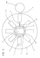
- the dispensing element 3 extends beyond the plan layout of the container (as schematically shown in Figure 3 ), for reasons that will be clarified below.
- Each container 2 is designed to contain food powders and has a substantially hopper-like structure.
- Each container 2 has a loading opening for receiving ingredients and an outlet in communication with the dispensing element 3.
- the device 1 further comprises a plurality of slides 4, each being coupled to a respective container 2.
- each slide 4 has wheels 5 for easy displacement thereof on a surface.
- the containers 2 are removably attached to the slides 4, which allows them to be removed by an operator for maintenance of the device 1. When the containers 2 are fitted onto their respective slides 4, the containers 2 and the slides 4 form a single rigid body.
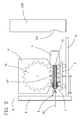
- the slides 4 are adapted to move between a rest position (as shown in Figure 2 ), in which the dispensing element lies distal from the preparation unit 100 and an operating position (as shown in Figure 1 ) in which the dispensing element 3 lies in a position in which it is at least partially inserted in the preparation unit 100, and particularly at least partially extends into the inlet 101 of the batch freezing cylinder.
- the device 1 a first actuator member 6, which is selectively operative on a single container 2 and/or its respective slide 4.
- the first actuator member 6 is operative on the container 2, which is rigidly joined to the slide 4 and transfers motion thereto. It shall be noted that the first actuator member 2 is operative on one container at a time, whereby a single actuator member 6 may be used for selectively moving all the containers 2 and their respective slides 4.
- Second actuator members 7 are also provided, which are operative on each container 2 and/or its respective slide 4, and are designed to mate with the first actuator member 6 to move the slide 4. In the preferred embodiment of the invention, the second actuator members 7 are directly operative on each container 2.
- the slides 4 and their containers 2 are supported by a rotary plate 8, which is adapted to rotate about an axis of rotation X.
- the rotary table 7 has a substantially circular shape and has a central hole with a post 9 extending therethrough, along the above mentioned axis X.
- the rotary table 8 is driven by an electric motor (not shown) via any appropriate mechanism (such as a rack and pinion arrangement).
- the electric motor is preferably equipped with an encoder to detect the position assumed by the rotary table at each instant.
- the slides 4 are slidably attached to one another in directions perpendicular to the axis of rotation X of the rotary table 4.
- elastic members 10 are provided (as schematically shown in Figures 1 and 2 ), which are operable between each slide 4 and the rotary table 8 and are designed to hold the slides 4 in the rest position, proximate to the post 9.
- each slide 4 ha a stem 4a which extends below and away from the slide, and through a straight slit formed in the rotary table 8. This slit radially extends on the rotary table, parallel to the direction of movement of the slide.
- An additional stem 8a is provided below the rotary table.
- the elastic member e.g. a spring
- the elastic member is operative between the two stems. with which said slides, said rotary table being adapted to rotate to bring a container and its respective slide in front of said first actuator member.
- the first actuator member 6 comprises a tooth 11 which rotates about an axis substantially perpendicular to the axis of rotation X of the rotary table 8. This rotating tooth 11 is carried by the post 9 and extends therefrom in a radially outward direction.
- the pin 11 is actuated by an electric motor (not shown) preferably having an encoder. The purpose of the tooth 11 is to rotate the second actuator members 7.
- each container 2 and comprise a cursor 12 which has a groove for coupling with the teeth 11, such that the rotation of the tooth 11 causes the rotation of the cursor 12.
- the cursor is rigidly joined to a threaded rod 13 extending in a direction perpendicular to the axis X and parallel to the direction of movement of the slides.
- the threaded rod 13 has, for instance, helical threads on its outer surface.
- the threaded rod is inserted in a threaded bushing 14 engaged on the container 2 (see Figure 4 ).
- the rotation of the threaded rod 13 will exert a force on the container, through its connection with the threaded bushing 14, thereby causing the slide 4 to move.
- the threaded bushing is inserted in a sleeve 15 which is joined to the container 2 (see Figure 4 ).
- a rotational clutch 16 is provided between the threaded bushing 14 and the sleeve 15, which rigidly joins the bushing 16 and the sleeve 15 when the torque transmitted between the threaded bushing and the sleeve 15 is below a threshold value, and allows the threaded bushing 14 to rotate in the sleeve 15 when the above torque exceeds the threshold value.
- the threaded bushing is connected to an auger 17 which extends in the container 2 and reaches said dispensing element 3.
- the auger 17 rotates with the threaded bushing 14, thereby pushing the powder ingredient in the container 2 toward the dispensing element 3, out of the container.
- a gear wheel 18 is provided in the container 2 to increase the effectiveness of the auger 17, which gear wheel meshes with the auger and more effectively conveys the powder material toward the bottom of the container 2 and hence toward the auger 17.
- the rotary table 8 In operation, when a particular food powder is to be fed into the batch freezer, the rotary table 8 is rotated until the container 2 that contains such particular powder comes to alignment with the first actuator member 6, for the tooth 11 to fit into the groove of the cursor 12.
- the post 9 has a guide ring 19 (see particularly Figure 3 ), which is designed to slidably engage the grooves of the cursors 12 when the slide is in the rest position.
- This guide ring 19 ensures that the grooves of the cursors maintain their orientation as the rotary table rotates, by preventing the rotation of the sliders 12. It shall be noted that in this step all the slides 4 are in the rest position, and held in this position by the elastic members 10.
- the cursor 11 is actuated, to cause the rotation of the threaded rod 13.
- the latter is unscrewed from the threaded bushing 14 with which it is engaged and causes the slide 4 to move forward toward the operating position. It shall be noted that in this step the threaded bushing 14 is rigidly joined to the container 2 and does not move (rotate) relative to it.
- any further rotation of the tooth 11 and the threaded rod 13 causes the clutch 16 to slip and, as a result, the threaded bushing 14 to rotate relative to the sleeve 15 (and hence relative to the container 2).
- the rotation of the threaded bushing 14 causes the rotation of the auger 17 which pushes the powders into the dispensing element 3.
- the rotation of the auger 17 causes in turn the rotation of the gear wheel 18, which assists the powders in reaching the bottom portion of the container 2.
- the dispensing element 3 has already penetrated the opening 101 of the batch freezer 100, for the powders to be directly dispensed into the batch freezer 2.
- the rotation of the tooth 11 continues until the right amount of powders is dispensed.
- the tooth 11 is rotated in the opposite direction.
- the clutch 16 stops the rotation of the threaded bushing 14 relative to the sleeve 15 and the slide 4 moves toward the rest position. Once this position has been reached, the cycle stops until a next powder dispensing request.
- the device 1 of the present invention allows the entire container to be moved to a position in which the ingredients can be directly dispensed into the preparation unit, thereby avoiding any dispersion of ingredients in the vending machine, and ensuring hygiene thereof.
Abstract
An ingredient loading device for preparation units of vending machine comprises a plurality of containers (2) for powder ingredients, having a dispensing element (3) designed to fit into an opening (101) of a preparation unit (100), a plurality of slides (4), coupled to a respective container (2), and adapted to move between a rest position distal from the preparation unit (100) and an operating position in which the dispensing element (3) is inserted in the preparation unit (100), a first actuator member (6) which is selectively operative on one container (2) at a time, and second actuator members (7) located on each container (2) and designed to mate with said actuator member (6) to move the slide (4). A rotary table (8) rotating about an axis of rotation (X), and having the slides (4) slidably engaged therewith, brings a container (2) in front of the first actuator member (6).
Description
- The present invention relates to an ingredient-loading device for preparation units of vending machines. Particularly, the present invention is advantageously employed for loading powders into preparation units for preparing beverages, sorbets, ice-creams and the like in vending machines.
- In the preparation of ice-cream products, such as ice-creams, slushes, sorbets, creams, sauces, semi-liquid chocolate, jellies and the like, but also in the preparation of beverages in vending machines, hygiene is of critical importance. Indeed, vending machines are not designed to undergo maintenance each time dispensing occurs, but only after many dispensing operations.
- Therefore, it is critical to ensure that all the ingredients required for preparing different products, such as slushes, ice-creams, beverages of different flavors will not mix, as well as that no food powder dispersion occurs between preparations.
- For this purpose, vending machines are designed to undergo periodic cleaning and sanitization cycles of all the devices involved in product preparation. Nevertheless, these cleaning cycles considerably complicate both the structure and the operation logic of vending machines, thereby increasing their operating costs and, in certain cases, affecting reliability.
- The Applicant believes that advantages would be obtained from equipping vending machines, and particularly vending machines for preparation of ice-cream products, with an ingredient-loading device that would dispense ingredients into the preparation device, e.g. a batch freezer, in as aseptic a manner as possible, i.e. without leaving product residues in the vending machine or near the batch freezer.
- Now, the object of the present invention is to provide an ingredient-loading device for preparation units of vending machines, that can introduce ingredients into a preparation device in controlled and hygienic fashion.
- This object is fulfilled by an ingredient-loading device for preparation units of vending machines as defined in one or more of the annexed claims.
- Further features and advantages of the ingredient-loading device for preparation units of vending machines according to the present invention will be apparent upon reading the following description of one preferred embodiment thereof, which is given by way of illustration and without limitation with reference to the accompanying figures, in which:
-
Figure 1 shows a partially sectional schematic lateral view of an ingredient-loading device for preparation units of vending machines according to the present invention, -
Figure 2 shows the device ofFigure 1 in a different operating position, -
Figure 3 shows a schematic plan view of the device ofFigure 1 , with certain parts omitted to better show other parts; and -
Figure 4 shows an enlarged view of a few details of the device ofFigure 1 . - The
device 1 as shown in the annexed figures has been represented schematically, and its parts are not necessarily illustrated to scale. - An ingredient-loading device for preparation units of vending machines according to the present invention will be generally designated by
numeral 1. - Reference will be made herein, as a preferred example of preparation unit concerned by the present invention, to a batch freezer for preparing ice-cream products from powder ingredients. Such type of batch freezer comprises a batch freezing cylinder, referenced 100 in the figures, which has a
hole 101 for receiving powders. A liquid is also introduced into the batch freezing cylinder, which is designed to mix with the powder ingredients. Thebatch freezing cylinder 100 may be partially surrounded by cooling members (not shown), which are designed to reduce the temperature of the cylinder walls to values ranging from -5 to -30°C, for example -15°C. - A pair of pistons are operative in the
batch freezing cylinder 100, and synchronously reciprocate therein. i.e. move up and down in the cylinder in synchronization with each other, to prepare the ice-cream product. Once such product has been prepared, it is ejected from an ejection opening of the batch freezing cylinder to be dispensed to the user. - The
device 1 comprises a plurality ofcontainers 2 for preferably powdered ingredients, each equipped with a dispensingelement 3 designed to at least partially fit into an opening 101 of apreparation unit 100. In the preferred embodiment of the invention, the dispensingelement 3 is a hollow cylinder, which is put in fluid communication with the interior of thecontainer 2 and extends away from such container. Preferably, the dispensingelement 3 extends beyond the plan layout of the container (as schematically shown inFigure 3 ), for reasons that will be clarified below. Eachcontainer 2 is designed to contain food powders and has a substantially hopper-like structure. Eachcontainer 2 has a loading opening for receiving ingredients and an outlet in communication with the dispensingelement 3. - The
device 1 further comprises a plurality ofslides 4, each being coupled to arespective container 2. In the preferred embodiment of the invention, eachslide 4 haswheels 5 for easy displacement thereof on a surface. Thecontainers 2 are removably attached to theslides 4, which allows them to be removed by an operator for maintenance of thedevice 1. When thecontainers 2 are fitted onto theirrespective slides 4, thecontainers 2 and theslides 4 form a single rigid body. Theslides 4 are adapted to move between a rest position (as shown inFigure 2 ), in which the dispensing element lies distal from thepreparation unit 100 and an operating position (as shown inFigure 1 ) in which the dispensingelement 3 lies in a position in which it is at least partially inserted in thepreparation unit 100, and particularly at least partially extends into theinlet 101 of the batch freezing cylinder. - In order to move the
slides 4, the device 1 afirst actuator member 6, which is selectively operative on asingle container 2 and/or itsrespective slide 4. In the preferred embodiment of the invention, thefirst actuator member 6 is operative on thecontainer 2, which is rigidly joined to theslide 4 and transfers motion thereto. It shall be noted that thefirst actuator member 2 is operative on one container at a time, whereby asingle actuator member 6 may be used for selectively moving all thecontainers 2 and theirrespective slides 4.Second actuator members 7 are also provided, which are operative on eachcontainer 2 and/or itsrespective slide 4, and are designed to mate with thefirst actuator member 6 to move theslide 4. In the preferred embodiment of the invention, thesecond actuator members 7 are directly operative on eachcontainer 2. - The
slides 4 and theircontainers 2 are supported by arotary plate 8, which is adapted to rotate about an axis of rotation X. The rotary table 7 has a substantially circular shape and has a central hole with apost 9 extending therethrough, along the above mentioned axis X. The rotary table 8 is driven by an electric motor (not shown) via any appropriate mechanism (such as a rack and pinion arrangement). The electric motor is preferably equipped with an encoder to detect the position assumed by the rotary table at each instant. Theslides 4 are slidably attached to one another in directions perpendicular to the axis of rotation X of the rotary table 4. In the preferred embodiment of the invention,elastic members 10 are provided (as schematically shown inFigures 1 and2 ), which are operable between eachslide 4 and the rotary table 8 and are designed to hold theslides 4 in the rest position, proximate to thepost 9. In the preferred embodiment of the invention, eachslide 4 ha astem 4a which extends below and away from the slide, and through a straight slit formed in the rotary table 8. This slit radially extends on the rotary table, parallel to the direction of movement of the slide. Anadditional stem 8a is provided below the rotary table. The elastic member (e.g. a spring) is operative between the two stems. with which said slides, said rotary table being adapted to rotate to bring a container and its respective slide in front of said first actuator member. - The
first actuator member 6 comprises atooth 11 which rotates about an axis substantially perpendicular to the axis of rotation X of the rotary table 8. This rotatingtooth 11 is carried by thepost 9 and extends therefrom in a radially outward direction. Thepin 11 is actuated by an electric motor (not shown) preferably having an encoder. The purpose of thetooth 11 is to rotate thesecond actuator members 7. - The latter, as mentioned above, are provided on each
container 2 and comprise acursor 12 which has a groove for coupling with theteeth 11, such that the rotation of thetooth 11 causes the rotation of thecursor 12. The cursor is rigidly joined to a threadedrod 13 extending in a direction perpendicular to the axis X and parallel to the direction of movement of the slides. The threadedrod 13 has, for instance, helical threads on its outer surface. The threaded rod is inserted in a threadedbushing 14 engaged on the container 2 (seeFigure 4 ). Thus, the rotation of the threadedrod 13 will exert a force on the container, through its connection with the threadedbushing 14, thereby causing theslide 4 to move. Depending on the direction of rotation of the tooth 11 (and hence the threaded rod 13), the slide will move either toward the rest position or the operating position, thereby moving the slide either toward the center or the periphery of the rotary table. The threaded bushing is inserted in asleeve 15 which is joined to the container 2 (seeFigure 4 ). Arotational clutch 16 is provided between the threadedbushing 14 and thesleeve 15, which rigidly joins thebushing 16 and thesleeve 15 when the torque transmitted between the threaded bushing and thesleeve 15 is below a threshold value, and allows the threadedbushing 14 to rotate in thesleeve 15 when the above torque exceeds the threshold value. Thus, when the slide is in the rest position and the tooth is actuated to move the slide toward the operating position, the torque transmitted between the threadedbushing 14 and thesleeve 15 is below the threshold value (it should be noted that in this state the torque transmitted by the tooth to the threadedbushing 14 is converted into a force that moves the slide forward). When the slide reaches the operating position and is prevented from further moving forward (e.g. by a mechanical limit stop member or by the action of the elastic members 10), the rotation of thetooth 11 generates a torque on the threaded bushing, which is entirely transmitted to thesleeve 15. This torque, which exceeds the threshold value, is no longer balanced by theclutch 16, whereby the bushing starts to rotate in the sleeve 15 (with the threaded bushing 13). - Advantageously, the threaded bushing is connected to an
auger 17 which extends in thecontainer 2 and reaches said dispensingelement 3. When the threadedbushing 14 rotates in thesleeve 15, theauger 17 rotates with the threadedbushing 14, thereby pushing the powder ingredient in thecontainer 2 toward the dispensingelement 3, out of the container. Agear wheel 18 is provided in thecontainer 2 to increase the effectiveness of theauger 17, which gear wheel meshes with the auger and more effectively conveys the powder material toward the bottom of thecontainer 2 and hence toward theauger 17. - In operation, when a particular food powder is to be fed into the batch freezer, the rotary table 8 is rotated until the
container 2 that contains such particular powder comes to alignment with thefirst actuator member 6, for thetooth 11 to fit into the groove of thecursor 12. For this purpose, thepost 9 has a guide ring 19 (see particularlyFigure 3 ), which is designed to slidably engage the grooves of thecursors 12 when the slide is in the rest position. Thisguide ring 19 ensures that the grooves of the cursors maintain their orientation as the rotary table rotates, by preventing the rotation of thesliders 12. It shall be noted that in this step all theslides 4 are in the rest position, and held in this position by theelastic members 10. - Then, the
cursor 11 is actuated, to cause the rotation of the threadedrod 13. The latter is unscrewed from the threadedbushing 14 with which it is engaged and causes theslide 4 to move forward toward the operating position. It shall be noted that in this step the threadedbushing 14 is rigidly joined to thecontainer 2 and does not move (rotate) relative to it. - When the slide reaches the operating position, any further rotation of the
tooth 11 and the threadedrod 13 causes the clutch 16 to slip and, as a result, the threadedbushing 14 to rotate relative to the sleeve 15 (and hence relative to the container 2). The rotation of the threadedbushing 14 causes the rotation of theauger 17 which pushes the powders into the dispensingelement 3. The rotation of theauger 17 causes in turn the rotation of thegear wheel 18, which assists the powders in reaching the bottom portion of thecontainer 2. When theslide 4 reaches the operating position, the dispensingelement 3 has already penetrated theopening 101 of thebatch freezer 100, for the powders to be directly dispensed into thebatch freezer 2. The rotation of thetooth 11 continues until the right amount of powders is dispensed. - At the end of this dispensing operation, the
tooth 11 is rotated in the opposite direction. The clutch 16 stops the rotation of the threadedbushing 14 relative to thesleeve 15 and theslide 4 moves toward the rest position. Once this position has been reached, the cycle stops until a next powder dispensing request. - All the above operations are automatically managed and actuated by a control and monitoring unit.
- Therefore, the
device 1 of the present invention allows the entire container to be moved to a position in which the ingredients can be directly dispensed into the preparation unit, thereby avoiding any dispersion of ingredients in the vending machine, and ensuring hygiene thereof. - Those skilled in the art will obviously appreciate that a number of changes and variants may be made to the arrangements as described hereinbefore to meet incidental and specific needs, and for instance the
slides 4 may be equipped with sliding blocks instead of the above mentionedwheels 5, and the rotary table may have a polygonal shape instead of a circular shape. All of these variants and changes fall within scope of the invention, as defined in the following claims.
Claims (10)
- An ingredient-loading device for preparation units of vending machines, comprising:a plurality of containers (2) for preferably powdered ingredients, each equipped with a dispensing element (3) designed to at least partially fit into an opening (101) of a preparation unit (100);a plurality of slides (4), each coupled to a respective container (2), said slides (4) being adapted to move between a rest position in which said dispensing element (3) lies distal from the preparation unit (100) and an operating position in which said dispensing element (3) lies in a position in which it is at least partially inserted in the preparation unit (100);a first actuator member (6), which is selectively operative on a single container (2) and/or its respective slide (4);second actuator members (7) which are operative and placed on each container (2) and/or its respective slide (4), and are designed to mate with said first actuator member (6) to actuate said slide (4) between the rest position and the operating position;a rotary table (8) rotating about an axis of rotation (X), with which said slides (4) are slidably engaged in directions perpendicular to said axis of rotation (X) said rotary table (8) being adapted to rotate to bring a container (2) and its respective slide (4) in front of said first actuator member (6).
- A device as claimed in claim 1, wherein said first actuator member (6) comprises a tooth (11) which rotates about an axis substantially perpendicular to the axis of rotation (X) of the rotary table (8); said rotating tooth (11) being designed to cause rotation of said second actuator members (7).
- A device as claimed in claim 2, wherein said second actuator members (7) comprise a cursor (12) having a groove, which is designed to mate with said tooth (11), said cursor (12) being joined to a threaded rod (13) engaged in a threaded bushing (14), which is in turn engaged on the container (2) and/or its respective slide (4); the rotation of said threaded rod (13) moving the slide (4) between the rest position and the operative position and vice versa.
- A device as claimed in claim 3, wherein said threaded bushing (14) is inserted in a sleeve (15) which is joined to the container (2); said threaded bushing (14) being connected to an auger (17) which extends in the container (2) and reaches said dispensing element (3) to feed ingredients thereto.
- A device as claimed in claim 4, wherein said threaded bushing (14) and said sleeve (15) are mutually engaged by a rotational clutch (16) such that said threaded bushing (14) rotates in said sleeve (15) when the torque transmitted between the threaded bushing (14) and the sleeve (15) is greater than a threshold value.
- A device as claimed in any of the preceding claims, comprising elastic members (10) operative between each slide (4) and said rotary table (8) to hold the slides (4) that are not engaged by the first actuator member (6) in the rest position.
- A device as claimed in any of the preceding claims, wherein each container (2) is removably engaged by its respective slide (4).
- A device as claimed in any of the preceding claims, comprising a vertical post (9) that carries said first actuator member (6); said rotary table (8) rotating about said post (9).
- A device as claimed in claim 8, wherein said post comprises a guide ring (19), which is designed to slidably engage the grooves of the cursors (12) of the second actuator members (7) of each slide (4) when the latter are in the rest position.
- A vending machine comprising a batch freezer and an ingredient-loading device as claimed in one or more of claims 1 to 9.
Applications Claiming Priority (1)
| Application Number | Priority Date | Filing Date | Title |
|---|---|---|---|
| ITMI20140791 | 2014-04-29 |
Publications (2)
| Publication Number | Publication Date |
|---|---|
| EP2939577A1 true EP2939577A1 (en) | 2015-11-04 |
| EP2939577A8 EP2939577A8 (en) | 2015-12-30 |
Family
ID=50981767
Family Applications (1)
| Application Number | Title | Priority Date | Filing Date |
|---|---|---|---|
| EP15165267.4A Withdrawn EP2939577A1 (en) | 2014-04-29 | 2015-04-27 | Ingredient-loading device for preparation units of vending machines |
Country Status (1)
| Country | Link |
|---|---|
| EP (1) | EP2939577A1 (en) |
Cited By (1)
| Publication number | Priority date | Publication date | Assignee | Title |
|---|---|---|---|---|
| WO2019050892A1 (en) * | 2017-09-06 | 2019-03-14 | Comana Fabio | Powdered supplement dispensing station |
Citations (4)
| Publication number | Priority date | Publication date | Assignee | Title |
|---|---|---|---|---|
| US5816455A (en) * | 1994-05-27 | 1998-10-06 | Specialty Equipment Companies, Inc. | Method and apparatus for frozen dessert dispensing |
| US20030085237A1 (en) * | 2001-11-02 | 2003-05-08 | Paul Kateman | Method and apparatus for producing and dispensing an aerated and/or blended food product |
| US20130032611A1 (en) * | 2011-08-03 | 2013-02-07 | Christopher Dooley | Powder Dispensing Apparatus |
| EP2676581A1 (en) * | 2012-06-20 | 2013-12-25 | F.A.S. International S.p.A. | A beverage preparation device for vending machines |
-
2015
- 2015-04-27 EP EP15165267.4A patent/EP2939577A1/en not_active Withdrawn
Patent Citations (4)
| Publication number | Priority date | Publication date | Assignee | Title |
|---|---|---|---|---|
| US5816455A (en) * | 1994-05-27 | 1998-10-06 | Specialty Equipment Companies, Inc. | Method and apparatus for frozen dessert dispensing |
| US20030085237A1 (en) * | 2001-11-02 | 2003-05-08 | Paul Kateman | Method and apparatus for producing and dispensing an aerated and/or blended food product |
| US20130032611A1 (en) * | 2011-08-03 | 2013-02-07 | Christopher Dooley | Powder Dispensing Apparatus |
| EP2676581A1 (en) * | 2012-06-20 | 2013-12-25 | F.A.S. International S.p.A. | A beverage preparation device for vending machines |
Cited By (1)
| Publication number | Priority date | Publication date | Assignee | Title |
|---|---|---|---|---|
| WO2019050892A1 (en) * | 2017-09-06 | 2019-03-14 | Comana Fabio | Powdered supplement dispensing station |
Also Published As
| Publication number | Publication date |
|---|---|
| EP2939577A8 (en) | 2015-12-30 |
Similar Documents
| Publication | Publication Date | Title |
|---|---|---|
| JP6555618B2 (en) | Beverage dispenser comprising a powder container and method for preparing a beverage using the same | |
| EP2345332B1 (en) | Apparatus and process for preparing frozen confectionery products | |
| US20060255066A1 (en) | Food beverage dispensing system | |
| CN109414034B (en) | Product dispensing machine | |
| CN101897379A (en) | Machine for making and dispensing food products such as ice creams, ice cream shakes and the like | |
| EP3735834C0 (en) | Stirring unit for a machine for batch freezing and dispensing ice cream products, machine comprising the stirring unit and method for making ice cream products | |
| EP3669661A1 (en) | Method and machine for making semi-liquid food products | |
| ATE498342T1 (en) | DEVICE FOR PREPARING AND DISTRIBUTING INFUSION PRODUCTS, IN PARTICULAR COFFEE, IN VARIABLE VOLUMETRIC QUANTITIES | |
| EP3573470B1 (en) | Shake product blending and dispensing process | |
| WO2013070834A1 (en) | Dual valve injector assembly for dispensing a food product | |
| EP2939577A1 (en) | Ingredient-loading device for preparation units of vending machines | |
| EP3302091B1 (en) | Chilled product processing apparatus | |
| WO2012007772A3 (en) | Dispensing apparatus and container for dispensing frozen confections | |
| WO2017108451A1 (en) | Beverage dispenser with powder container | |
| JP2020500608A (en) | Dosing device, beverage dispensing device and worm body | |
| US1676377A (en) | Unit-measuring machine | |
| WO2016091830A1 (en) | Beverage dispenser with powder container | |
| EP2186421B1 (en) | Device for the production of soft ice cream or similar products, with portioning device and portions counting device | |
| EP3031367A1 (en) | Beverage dispenser with powder container | |
| KR101066402B1 (en) | Impromptu icecream maker | |
| EP2713765B1 (en) | Apparatus for preparing refrigerated products | |
| EP3474246A1 (en) | Automatic dispenser of food products, particularly for dispensing food toppings | |
| KR200401406Y1 (en) | Production line for twist ice-cackes | |
| JP2007282611A (en) | Frozen dessert producing apparatus, and addition apparatus for the same | |
| EP2661964A1 (en) | Variable diameter, variable pitch auger with material scraper and breaker bar |
Legal Events
| Date | Code | Title | Description |
|---|---|---|---|
| PUAI | Public reference made under article 153(3) epc to a published international application that has entered the european phase |
Free format text: ORIGINAL CODE: 0009012 |
|
| AK | Designated contracting states |
Kind code of ref document: A1 Designated state(s): AL AT BE BG CH CY CZ DE DK EE ES FI FR GB GR HR HU IE IS IT LI LT LU LV MC MK MT NL NO PL PT RO RS SE SI SK SM TR |
|
| AX | Request for extension of the european patent |
Extension state: BA ME |
|
| RAP1 | Party data changed (applicant data changed or rights of an application transferred) |
Owner name: FAS INTERNATIONAL S.P.A. |
|
| STAA | Information on the status of an ep patent application or granted ep patent |
Free format text: STATUS: THE APPLICATION IS DEEMED TO BE WITHDRAWN |
|
| 18D | Application deemed to be withdrawn |
Effective date: 20160505 |