EP3012492A1 - Sliding seal - Google Patents
Sliding seal Download PDFInfo
- Publication number
- EP3012492A1 EP3012492A1 EP15190708.6A EP15190708A EP3012492A1 EP 3012492 A1 EP3012492 A1 EP 3012492A1 EP 15190708 A EP15190708 A EP 15190708A EP 3012492 A1 EP3012492 A1 EP 3012492A1
- Authority
- EP
- European Patent Office
- Prior art keywords
- seal
- section
- sections
- base
- circumferential
- Prior art date
- Legal status (The legal status is an assumption and is not a legal conclusion. Google has not performed a legal analysis and makes no representation as to the accuracy of the status listed.)
- Granted
Links
- 239000000919 ceramic Substances 0.000 claims description 13
- 239000000463 material Substances 0.000 claims description 11
- 239000002131 composite material Substances 0.000 claims description 7
- 229910001092 metal group alloy Inorganic materials 0.000 claims description 7
- 239000000835 fiber Substances 0.000 claims description 6
- 239000002657 fibrous material Substances 0.000 claims description 6
- 239000002184 metal Substances 0.000 claims description 5
- 229910052751 metal Inorganic materials 0.000 claims description 5
- 238000007789 sealing Methods 0.000 claims description 5
- 239000011248 coating agent Substances 0.000 claims description 4
- 238000000576 coating method Methods 0.000 claims description 4
- 239000007789 gas Substances 0.000 description 14
- 239000000446 fuel Substances 0.000 description 5
- 230000003068 static effect Effects 0.000 description 3
- PXHVJJICTQNCMI-UHFFFAOYSA-N Nickel Chemical compound [Ni] PXHVJJICTQNCMI-UHFFFAOYSA-N 0.000 description 2
- 230000003466 anti-cipated effect Effects 0.000 description 2
- 230000008859 change Effects 0.000 description 2
- 238000012986 modification Methods 0.000 description 2
- 230000004048 modification Effects 0.000 description 2
- 230000009467 reduction Effects 0.000 description 2
- 229910045601 alloy Inorganic materials 0.000 description 1
- 239000000956 alloy Substances 0.000 description 1
- 230000004075 alteration Effects 0.000 description 1
- 229910010293 ceramic material Inorganic materials 0.000 description 1
- 238000004891 communication Methods 0.000 description 1
- 230000006835 compression Effects 0.000 description 1
- 238000007906 compression Methods 0.000 description 1
- 238000010276 construction Methods 0.000 description 1
- 230000008602 contraction Effects 0.000 description 1
- 238000013016 damping Methods 0.000 description 1
- 230000000694 effects Effects 0.000 description 1
- 239000007788 liquid Substances 0.000 description 1
- 230000007246 mechanism Effects 0.000 description 1
- 229910052759 nickel Inorganic materials 0.000 description 1
- 230000001737 promoting effect Effects 0.000 description 1
- 230000004044 response Effects 0.000 description 1
Images


Classifications
-
- F—MECHANICAL ENGINEERING; LIGHTING; HEATING; WEAPONS; BLASTING
- F01—MACHINES OR ENGINES IN GENERAL; ENGINE PLANTS IN GENERAL; STEAM ENGINES
- F01D—NON-POSITIVE DISPLACEMENT MACHINES OR ENGINES, e.g. STEAM TURBINES
- F01D11/00—Preventing or minimising internal leakage of working-fluid, e.g. between stages
- F01D11/005—Sealing means between non relatively rotating elements
-
- F—MECHANICAL ENGINEERING; LIGHTING; HEATING; WEAPONS; BLASTING
- F16—ENGINEERING ELEMENTS AND UNITS; GENERAL MEASURES FOR PRODUCING AND MAINTAINING EFFECTIVE FUNCTIONING OF MACHINES OR INSTALLATIONS; THERMAL INSULATION IN GENERAL
- F16J—PISTONS; CYLINDERS; SEALINGS
- F16J15/00—Sealings
- F16J15/02—Sealings between relatively-stationary surfaces
- F16J15/06—Sealings between relatively-stationary surfaces with solid packing compressed between sealing surfaces
- F16J15/08—Sealings between relatively-stationary surfaces with solid packing compressed between sealing surfaces with exclusively metal packing
- F16J15/0887—Sealings between relatively-stationary surfaces with solid packing compressed between sealing surfaces with exclusively metal packing the sealing effect being obtained by elastic deformation of the packing
-
- F—MECHANICAL ENGINEERING; LIGHTING; HEATING; WEAPONS; BLASTING
- F16—ENGINEERING ELEMENTS AND UNITS; GENERAL MEASURES FOR PRODUCING AND MAINTAINING EFFECTIVE FUNCTIONING OF MACHINES OR INSTALLATIONS; THERMAL INSULATION IN GENERAL
- F16J—PISTONS; CYLINDERS; SEALINGS
- F16J15/00—Sealings
- F16J15/02—Sealings between relatively-stationary surfaces
- F16J15/06—Sealings between relatively-stationary surfaces with solid packing compressed between sealing surfaces
- F16J15/10—Sealings between relatively-stationary surfaces with solid packing compressed between sealing surfaces with non-metallic packing
- F16J15/104—Sealings between relatively-stationary surfaces with solid packing compressed between sealing surfaces with non-metallic packing characterised by structure
-
- F—MECHANICAL ENGINEERING; LIGHTING; HEATING; WEAPONS; BLASTING
- F05—INDEXING SCHEMES RELATING TO ENGINES OR PUMPS IN VARIOUS SUBCLASSES OF CLASSES F01-F04
- F05D—INDEXING SCHEME FOR ASPECTS RELATING TO NON-POSITIVE-DISPLACEMENT MACHINES OR ENGINES, GAS-TURBINES OR JET-PROPULSION PLANTS
- F05D2220/00—Application
- F05D2220/30—Application in turbines
- F05D2220/32—Application in turbines in gas turbines
-
- F—MECHANICAL ENGINEERING; LIGHTING; HEATING; WEAPONS; BLASTING
- F05—INDEXING SCHEMES RELATING TO ENGINES OR PUMPS IN VARIOUS SUBCLASSES OF CLASSES F01-F04
- F05D—INDEXING SCHEME FOR ASPECTS RELATING TO NON-POSITIVE-DISPLACEMENT MACHINES OR ENGINES, GAS-TURBINES OR JET-PROPULSION PLANTS
- F05D2240/00—Components
- F05D2240/55—Seals
Definitions
- the present disclosure is generally related to seals and, more specifically, to a sliding seal.
- Seals are used in many applications to prevent or limit the flow of a gas or liquid from one side of the seal to another side of the seal.
- seals are used in many areas within a gas turbine engine to seal the gas path of the engine.
- the performance of gas path seals affects engine component efficiency.
- the loss of secondary flow into the gas path of a turbine engine has a negative effect on engine fuel burn, performance/efficiency, and component life.
- a metal w-seal or a non-metallic rope seal are typical seals used to seal or limit secondary flow between segmented or full-hoop turbine components.
- exposure to significant relative deflections between adjacent components and/or elevated temperatures can preclude the use of these types of seals or cause them to fail prematurely.
- a w-seal will deform and become ineffective.
- Using a higher strength material improves deflection capability somewhat, but generally at the expense of limiting temperature capability.
- Wear resistance can be a problem as well in an environment of significant relative motion.
- a rope seal typically has high temperature capability but has even less flexibility.
- a seal for sealing a space defined by first and second circumferential components comprising: a first seal section including a first base defining a ramped surface and a first leg extending from the first base, wherein an angle between the first base and the first leg comprises greater than 90 degrees; and a second seal section in sliding contact with the ramped surface; wherein the first seal section is configured to sealingly engage with the first circumferential component along a single first circumferential line of contact and to sealingly engage with the second circumferential component along a single second circumferential line of contact; and wherein the second seal section is configured to sealingly engage with the second circumferential component along a single third circumferential line of contact; and wherein the first and second seal sections are configured to move relative to one another.
- the second seal section includes a second base and a second leg extending from the second base, wherein the second base is in sliding contact with the ramped surface.
- the seal is formed from a material selected from one of a high-temperature metal alloy, a high-temperature ceramic fiber material, and a high-temperature ceramic fiber composite, or a combination of two or more of a high-temperature metal alloy, a high-temperature ceramic fiber material and a high-temperature ceramic fiber composite.
- a coating is applied to at least a portion of each of the first and second seal sections.
- a sheath is provided covering at least a portion of each of the first and second seal sections.
- first and second seal sections are substantially annular.
- first and second seal sections respectively define first and second gaps at respective opposed ends thereof.
- a bridging seal is disposed adjacent the first and second seal sections and at least partially covering the first and second gaps.
- first and second seal sections comprise machined rings.
- first and second seal sections comprise formed sheet metal.
- a system comprising: a first circumferential component including a first surface; a second circumferential component including a second surface, the second circumferential component disposed adjacent the first circumferential component and defining a seal cavity therebetween; and a seal disposed in the seal cavity, the seal including: a first seal section including a first base defining a ramped surface and a first leg extending from the first base, wherein an angle between the first base and the first leg comprises greater than 90 degrees; and a second seal section in sliding contact with the ramped surface; wherein the first seal section is configured to sealingly engage with the first circumferential component along a single first circumferential line of contact and to sealingly engage with the second circumferential component along a single second circumferential line of contact; and wherein the second seal section is configured to sealingly engage with the second circumferential component along a single third circumferential line of contact; and wherein pressure within the seal cavity urges the seal to seat against the first surface and the second surface; and wherein
- the second seal section includes a second base and a second leg extending from the second base, wherein the second base is in sliding contact with the ramped surface.
- the seal is formed from a material selected from one of a high-temperature metal alloy, a high-temperature ceramic fiber material, and a high-temperature ceramic fiber composite, or a combination of two or more of a high-temperature metal alloy, a high-temperature ceramic fiber material and a high-temperature ceramic fiber composite.
- a coating is applied to at least a portion of each of the first and second seal sections.
- a sheath is provided covering at least a portion of each of the first and second seal sections.
- first and second seal sections are substantially annular.
- first and second seal sections respectively define first and second gaps at respective opposed ends thereof.
- a bridging seal is disposed adjacent the first and second seal sections and at least partially covering the first and second gaps.
- first and second seal sections comprise machined rings.
- first and second seal sections comprise formed sheet metal.
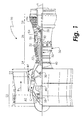
- FIG. 1 schematically illustrates a gas turbine engine 20.
- the gas turbine engine 20 is disclosed herein as a two-spool turbofan that generally incorporates a fan section 22, a compressor section 24, a combustor section 26 and a turbine section 28.
- Alternative engines might include an augmentor section (not shown) among other systems or features.
- the fan section 22 drives air along a bypass flow path B in a bypass duct, while the compressor section 24 drives air along a core flow path C for compression and communication into the combustor section 26 then expansion through the turbine section 28.
- the exemplary engine 20 generally includes a low speed spool 30 and a high speed spool 32 mounted for rotation about an engine central longitudinal axis A relative to an engine static structure 36 via several bearing systems 38. It should be understood that various bearing systems 38 at various locations may alternatively or additionally be provided, and the location of bearing systems 38 may be varied as appropriate to the application.
- the low speed spool 30 generally includes an inner shaft 40 that interconnects a fan 42, a low pressure compressor 44 and a low pressure turbine 46.
- the inner shaft 40 is connected to the fan 42 through a speed change mechanism, which in exemplary gas turbine engine 20 is illustrated as a geared architecture 48 to drive the fan 42 at a lower speed than the low speed spool 30.
- the high speed spool 32 includes an outer shaft 50 that interconnects a high pressure compressor 52 and high pressure turbine 54.
- a combustor 56 is arranged in exemplary gas turbine 20 between the high pressure compressor 52 and the high pressure turbine 54.
- An engine static structure 36 is arranged generally between the high pressure turbine 54 and the low pressure turbine 46.
- the engine static structure 36 further supports bearing systems 38 in the turbine section 28.
- the inner shaft 40 and the outer shaft 50 are concentric and rotate via bearing systems 38 about the engine central longitudinal axis A which is collinear with their longitudinal axes.
- each of the positions of the fan section 22, compressor section 24, combustor section 26, turbine section 28, and fan drive gear system 48 may be varied.
- gear system 48 may be located aft of combustor section 26 or even aft of turbine section 28, and fan section 22 may be positioned forward or aft of the location of gear system 48.
- the engine 20 in one example is a high-bypass geared aircraft engine.
- the engine 20 bypass ratio is greater than about six (6:1), with an example embodiment being greater than about ten (10:1)
- the geared architecture 48 is an epicyclic gear train, such as a planetary gear system or other gear system, with a gear reduction ratio of greater than about 2.3
- the low pressure turbine 46 has a pressure ratio that is greater than about five (5:1).
- the engine 20 bypass ratio is greater than about ten (10:1)
- the fan diameter is significantly larger than that of the low pressure compressor 44
- the low pressure turbine 46 has a pressure ratio that is greater than about five (5:1).
- Low pressure turbine 46 pressure ratio is pressure measured prior to inlet of low pressure turbine 46 as related to the pressure at the outlet of the low pressure turbine 46 prior to an exhaust nozzle.
- the geared architecture 48 may be an epicycle gear train, such as a planetary gear system or other gear system, with a gear reduction ratio of greater than about 2.3:1. It should be understood, however, that the above parameters are only exemplary of one embodiment of a geared architecture engine and that the present invention is applicable to other gas turbine engines including direct drive turbofans.
- the fan section 22 of the engine 20 is designed for a particular flight condition -- typically cruise at about 0.8 Mach and about 35,000 feet (10,668 meters).
- the flight condition of 0.8 Mach and 35,000 ft (10,668 meters), with the engine at its best fuel consumption - also known as "bucket cruise Thrust Specific Fuel Consumption ('TSFC')" - is the industry standard parameter of lbm of fuel being burned divided by lbf of thrust the engine produces at that minimum point.
- "Low fan pressure ratio” is the pressure ratio across the fan blade alone, without a Fan Exit Guide Vane (“FEGV”) system.
- the low fan pressure ratio as disclosed herein according to one non-limiting embodiment is less than about 1.45.
- Low corrected fan tip speed is the actual fan tip speed in ft/sec divided by an industry standard temperature correction of [(Tram °R) / (518.7 °R)] 0.5 .
- the "Low corrected fan tip speed” as disclosed herein according to one non-limiting embodiment is less than about 1150 ft / second (350.5 m/sec).
- FIG. 2 schematically illustrates a cross-sectional view of a seal cavity 100 formed by two axially-adjacent segmented or full-hoop circumferential turbine components 102 and 104 which may move axially, radially, and/or circumferentially relative to one another about an axial centerline of the turbine engine.
- turbine components are used to demonstrate the positioning and functioning of the seals disclosed herein, this is done by way of illustration only and the seals disclosed herein may be used in other applications.
- a nominal design clearance 106 exists between the components 102 and 104.
- annular w-seal 108 formed from a material appropriate to the anticipated operating conditions (e.g., deflection, temperature, pressure, etc.) of the w-seal 108, such a nickel-based alloy to name just one non-limiting example.
- the design and material used in the construction of the w-seal 108 causes it to be deflected both forward and aft within the cavity 100, thereby causing it to seat against the components 102 and 104, even when the components 102 and 104 move relative to each other causing the clearance 106 to change.
- a w-seal 108 may deform, causing it to become ineffective and potentially liberate.
- FIG. 3 schematically illustrates a cross-sectional view of a seal cavity 200 formed by two axially-adjacent segmented or full hoop circumferential turbine components 202 and 204 which may move axially, radially, and circumferentially relative to one another about an axial centerline of the turbine engine.
- a nominal design clearance 206 exists between the components 202 and 204.
- Component 202 includes a surface 208 facing the seal cavity 200 and component 204 includes surfaces 210 and 211 facing the seal cavity 200.
- the seal 212 is formed from a first seal section 216 and a second seal section 214.
- the second seal section 214 includes a base 218 and a leg 220.
- the first seal section 216 includes a base 222 and a leg 224.
- the axis of the leg 224 forms an angle of greater than 90° with the axis of the base 222 such that the base 222 includes a ramped surface 226 against which the second seal section 214 abuts.
- the seal 212 may include a coating and/or a sheath to provide increased wear resistance.
- the base 218 includes a substantially rounded end 219 in contact with the ramped surface 226 such that the base 218 contacts the ramped surface 226 along a single circumferential line of contact.
- the phrase "circumferential line of contact” includes lines with a nominal radial thickness and such lines may be discontinuous (such at a location where the seal section is split).
- the leg 220 includes a substantially rounded end 221 in contact with the surface 210 such that the leg 220 contacts the surface 210 along a single circumferential line of contact.
- the seal section 214 contacts the component 204 along a single circumferential line of contact.
- the base 222 includes a substantially rounded end 223 in contact with the component 204 such that the base 222 contacts the component 204 along a single circumferential line of contact.
- the leg 224 includes a substantially rounded end 225 in contact with the surface 208 such that the leg 224 contacts the surface 208 along a single circumferential line of contact.
- the seal section 216 contacts the component 202 along a single circumferential line of contact and contacts the component 204 along a single circumferential line of contact.
- a secondary flow cavity 228 Pressure in a secondary flow cavity 228 is transmitted to the seal cavity 200 through an opening defined by the components 202, 204.
- This pressure acts upon the surfaces of the seal sections 214, 216, thereby causing the base 218 to seat against the ramped surface 226 of the base 222.
- the legs 220 and 224 increase the piston area upon which the pressure in the secondary flow cavity 228 operates, thereby causing the seal sections 214 and 216 to significantly load (and thereby seal) against the surfaces of the components 202 and 204.
- the angle of the ramped surface 226 causes the seal sections 214, 216 to be biased axially away from one another, thereby causing the leg 224 to seat against the surface 208 of the component 202 and the leg 220 to seat against the surface 210 of the component 204.
- the load applied by base 218 to base 222 also helps base 222 to seat against the surface 211, thereby providing a secondary seal against flow that may leak past the leg 220/surface 210 interface, such as during engine start-up, for example. This prevents most or all of the secondary flow cavity 228 gases from reaching the design clearance 206 area.
- the seal sections 214, 216 are free to slide relative to one another in the axial, circumferential and radial directions while the pressure forces acting upon the piston surfaces of the seal sections 214, 216 load the seal 212 so that it remains in contact with both components 202 and 204 as shown. Therefore, sealing is maintained while the components 202 and 204 and the components of the seal 212 move relative to one another.
- the seal 212 is not substantially deflected by the relative movement between the components 202 and 204 and the seal sections 214, 216 may be formed from significantly thicker material and/or a lower strength material than that used in the w-seal 108.
- the seal sections 214, 216 may be formed as machined rings, to name just one non-limiting embodiment.
- the seal sections 214, 216 may be formed to be undersized (as compared to the inner radial dimension of the cavity 200) in the free state to create additional inboard radial load. Such additional inboard radial load, acting upon the ramped surface 226, will also cause additional axial load, resulting in addition axial/radial load at the four sealing surfaces.
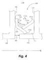
- FIG. 4 Another embodiment of the seal 212 is illustrated in FIG. 4 and designated as 212a.
- the seal section 214a is not divided into a base and a leg as in the embodiment of FIG. 3 . Notwithstanding this, the seal section 214a still slides upon the ramped surface 226 as relative deflection occurs between the components 202 and 204.
- FIG. 5 A further embodiment of the seal 212 is illustrated in FIG. 5 and designated as 212b.
- the seal sections 214b and 216a are shaped to facilitate forming them from sheet metal, to name just one non-limiting example. Notwithstanding this, the seal section 214b still slides upon the ramped surface 226a as relative deflection occurs between the components 202 and 204.
- the annular seal 212 may define a gap 230 therein to allow for expansion and contraction of the seal 212 relative to component 204.
- the gap 230 may be partially or substantially covered by a bridging seal 232 that extends a distance on either side of the gap 230.
- the bridging seal 232 is a discrete piece and is attached to the seal 212 on one side of the gap 230.
- the bridging seal 232 is integrally formed with the seal 212 as an extension on one side of the gap 230.
- the bridging seal 232 nests within a portion of the seal 212 to bridge the gap 230, such that the bridging seal 232 seats against the seal 212 in the area of the gap 230.
- the pressure transmitted to the seal cavity 200 will act upon the bridging seal 232 to press in against the seal 212, thereby partially or substantially sealing the gap 230.
- the seal section 214 is a complete full hoop (i.e., not split).
- the seal 212 is not deflected as the components 202 and 204 move relative to each other during engine assembly and engine operation. Because of the seal 212's increased resilience due to sliding rather than flexing, the seal 212 exhibits increased durability because it is tolerant of additional axial deflection. Additionally, the seal 212 can be made from a lower strength material that may be lower cost, have higher temperature capability, be more manufacturable, and/or more wear-resistant because thicker sheet stock (or thicker machined rings) may be used and lower strength lubricious material may be used. Additionally, the seal is less susceptible to distortion or breakage, which can cause leakage of gas past the seal 212 and/or liberation of the seal.
- the seal 212 exhibits improved vibration tolerance due to friction damping.
- the seal 212 is also less complex/costly to produce, and the bridging seal 232 at the gap 230 will be more secure because the added stiffness of the bridging seal 232 does not impact seal functionality as it would with the seal 108 that must be deflected to seal properly.
- providing a bridging seal to cover a gap in the seal 108 will increase the effective thickness of the seal 108 in the area of the bridging seal. Because the seal 108 must be deflected in order to seal against the surfaces of the seal cavity 100, the added thickness in the area of the bridging seal will increase the stiffness of the seal 108 in this area, reducing its ability to deflect.
Abstract
Description
- The present disclosure is generally related to seals and, more specifically, to a sliding seal.
- Seals are used in many applications to prevent or limit the flow of a gas or liquid from one side of the seal to another side of the seal. For example, seals are used in many areas within a gas turbine engine to seal the gas path of the engine. The performance of gas path seals affects engine component efficiency. For example, the loss of secondary flow into the gas path of a turbine engine has a negative effect on engine fuel burn, performance/efficiency, and component life. A metal w-seal or a non-metallic rope seal are typical seals used to seal or limit secondary flow between segmented or full-hoop turbine components. However, exposure to significant relative deflections between adjacent components and/or elevated temperatures can preclude the use of these types of seals or cause them to fail prematurely. If subjected to significant deflections, a w-seal will deform and become ineffective. Using a higher strength material improves deflection capability somewhat, but generally at the expense of limiting temperature capability. Wear resistance can be a problem as well in an environment of significant relative motion. A rope seal typically has high temperature capability but has even less flexibility.
- Improvements in seal design are therefore needed in the art.
- In one embodiment, a seal for sealing a space defined by first and second circumferential components is disclosed, the seal comprising: a first seal section including a first base defining a ramped surface and a first leg extending from the first base, wherein an angle between the first base and the first leg comprises greater than 90 degrees; and a second seal section in sliding contact with the ramped surface; wherein the first seal section is configured to sealingly engage with the first circumferential component along a single first circumferential line of contact and to sealingly engage with the second circumferential component along a single second circumferential line of contact; and wherein the second seal section is configured to sealingly engage with the second circumferential component along a single third circumferential line of contact; and wherein the first and second seal sections are configured to move relative to one another.
- In a further embodiment of the above, the second seal section includes a second base and a second leg extending from the second base, wherein the second base is in sliding contact with the ramped surface.
- In a further embodiment of any of the above, the seal is formed from a material selected from one of a high-temperature metal alloy, a high-temperature ceramic fiber material, and a high-temperature ceramic fiber composite, or a combination of two or more of a high-temperature metal alloy, a high-temperature ceramic fiber material and a high-temperature ceramic fiber composite.
- In a further embodiment of any of the above, a coating is applied to at least a portion of each of the first and second seal sections.
- In a further embodiment of any of the above, a sheath is provided covering at least a portion of each of the first and second seal sections.
- In a further embodiment of any of the above, the first and second seal sections are substantially annular.
- In a further embodiment of any of the above, the first and second seal sections respectively define first and second gaps at respective opposed ends thereof.
- In a further embodiment of any of the above, a bridging seal is disposed adjacent the first and second seal sections and at least partially covering the first and second gaps.
- In a further embodiment of any of the above, the first and second seal sections comprise machined rings.
- In a further embodiment of any of the above, the first and second seal sections comprise formed sheet metal.
- In another embodiment, a system is disclosed, comprising: a first circumferential component including a first surface; a second circumferential component including a second surface, the second circumferential component disposed adjacent the first circumferential component and defining a seal cavity therebetween; and a seal disposed in the seal cavity, the seal including: a first seal section including a first base defining a ramped surface and a first leg extending from the first base, wherein an angle between the first base and the first leg comprises greater than 90 degrees; and a second seal section in sliding contact with the ramped surface; wherein the first seal section is configured to sealingly engage with the first circumferential component along a single first circumferential line of contact and to sealingly engage with the second circumferential component along a single second circumferential line of contact; and wherein the second seal section is configured to sealingly engage with the second circumferential component along a single third circumferential line of contact; and wherein pressure within the seal cavity urges the seal to seat against the first surface and the second surface; and wherein relative movement of the first component and the second component toward or away from one another causes the second seal section to slide on the ramped surface of the first seal section such that the seal is not substantially deflected.
- In a further embodiment of any of the above, the second seal section includes a second base and a second leg extending from the second base, wherein the second base is in sliding contact with the ramped surface.
- In a further embodiment of any of the above, the seal is formed from a material selected from one of a high-temperature metal alloy, a high-temperature ceramic fiber material, and a high-temperature ceramic fiber composite, or a combination of two or more of a high-temperature metal alloy, a high-temperature ceramic fiber material and a high-temperature ceramic fiber composite.
- In a further embodiment of any of the above, a coating is applied to at least a portion of each of the first and second seal sections.
- In a further embodiment of any of the above, a sheath is provided covering at least a portion of each of the first and second seal sections.
- In a further embodiment of any of the above, the first and second seal sections are substantially annular.
- In a further embodiment of any of the above, the first and second seal sections respectively define first and second gaps at respective opposed ends thereof.
- In a further embodiment of any of the above, a bridging seal is disposed adjacent the first and second seal sections and at least partially covering the first and second gaps.
- In a further embodiment of any of the above, the first and second seal sections comprise machined rings.
- In a further embodiment of any of the above, the first and second seal sections comprise formed sheet metal.
- Other embodiments are also disclosed.
- The embodiments and other features, advantages and disclosures contained herein, and the manner of attaining them, will become apparent and the present disclosure will be better understood by reference to the following description of various exemplary embodiments of the present disclosure taken in conjunction with the accompanying drawings, wherein:
-
FIG. 1 is a schematic partial cross-sectional view of a gas turbine engine in an embodiment. -
FIG. 2 is a schematic cross-sectional view of a seal and seal cavity in an embodiment. -
FIG. 3 is a schematic cross-sectional view of a seal and seal cavity in an embodiment. -
FIG. 4 is a schematic cross-sectional view of a seal and seal cavity in an embodiment. -
FIG. 5 is a schematic cross-sectional view of a seal and seal cavity in an embodiment. -
FIG. 6 is a schematic perspective view of a seal in an embodiment. -
FIG. 7 is a schematic cross-sectional view of a seal and a bridging seal in an embodiment. - For the purposes of promoting an understanding of the principles of the invention, reference will now be made to certain embodiments and specific language will be used to describe the same. It will nevertheless be understood that no limitation of the scope of the invention is thereby intended, and alterations and modifications in the illustrated device, and further applications of the principles of the invention as illustrated therein are herein contemplated as would normally occur to one skilled in the art to which the invention relates.
-
FIG. 1 schematically illustrates agas turbine engine 20. Thegas turbine engine 20 is disclosed herein as a two-spool turbofan that generally incorporates afan section 22, acompressor section 24, acombustor section 26 and aturbine section 28. Alternative engines might include an augmentor section (not shown) among other systems or features. Thefan section 22 drives air along a bypass flow path B in a bypass duct, while thecompressor section 24 drives air along a core flow path C for compression and communication into thecombustor section 26 then expansion through theturbine section 28. Although depicted as a two-spool turbofan gas turbine engine in the disclosed non-limiting embodiment, it should be understood that the concepts described herein are not limited to use with two-spool turbofans as the teachings may be applied to other types of turbine engines including three-spool architectures. - The
exemplary engine 20 generally includes alow speed spool 30 and ahigh speed spool 32 mounted for rotation about an engine central longitudinal axis A relative to an enginestatic structure 36 viaseveral bearing systems 38. It should be understood thatvarious bearing systems 38 at various locations may alternatively or additionally be provided, and the location ofbearing systems 38 may be varied as appropriate to the application. - The
low speed spool 30 generally includes aninner shaft 40 that interconnects afan 42, alow pressure compressor 44 and alow pressure turbine 46. Theinner shaft 40 is connected to thefan 42 through a speed change mechanism, which in exemplarygas turbine engine 20 is illustrated as a gearedarchitecture 48 to drive thefan 42 at a lower speed than thelow speed spool 30. Thehigh speed spool 32 includes anouter shaft 50 that interconnects ahigh pressure compressor 52 andhigh pressure turbine 54. Acombustor 56 is arranged inexemplary gas turbine 20 between thehigh pressure compressor 52 and thehigh pressure turbine 54. An enginestatic structure 36 is arranged generally between thehigh pressure turbine 54 and thelow pressure turbine 46. The enginestatic structure 36 further supports bearingsystems 38 in theturbine section 28. Theinner shaft 40 and theouter shaft 50 are concentric and rotate viabearing systems 38 about the engine central longitudinal axis A which is collinear with their longitudinal axes. - The core airflow is compressed by the
low pressure compressor 44 then thehigh pressure compressor 52, mixed and burned with fuel in thecombustor 56, then expanded over thehigh pressure turbine 54 andlow pressure turbine 46. Theturbines low speed spool 30 andhigh speed spool 32 in response to the expansion. It will be appreciated that each of the positions of thefan section 22,compressor section 24,combustor section 26,turbine section 28, and fandrive gear system 48 may be varied. For example,gear system 48 may be located aft ofcombustor section 26 or even aft ofturbine section 28, andfan section 22 may be positioned forward or aft of the location ofgear system 48. - The
engine 20 in one example is a high-bypass geared aircraft engine. In a further example, theengine 20 bypass ratio is greater than about six (6:1), with an example embodiment being greater than about ten (10:1), the gearedarchitecture 48 is an epicyclic gear train, such as a planetary gear system or other gear system, with a gear reduction ratio of greater than about 2.3 and thelow pressure turbine 46 has a pressure ratio that is greater than about five (5:1). In one disclosed embodiment, theengine 20 bypass ratio is greater than about ten (10:1), the fan diameter is significantly larger than that of thelow pressure compressor 44, and thelow pressure turbine 46 has a pressure ratio that is greater than about five (5:1).Low pressure turbine 46 pressure ratio is pressure measured prior to inlet oflow pressure turbine 46 as related to the pressure at the outlet of thelow pressure turbine 46 prior to an exhaust nozzle. The gearedarchitecture 48 may be an epicycle gear train, such as a planetary gear system or other gear system, with a gear reduction ratio of greater than about 2.3:1. It should be understood, however, that the above parameters are only exemplary of one embodiment of a geared architecture engine and that the present invention is applicable to other gas turbine engines including direct drive turbofans. - A significant amount of thrust is provided by the bypass flow B due to the high bypass ratio. The
fan section 22 of theengine 20 is designed for a particular flight condition -- typically cruise at about 0.8 Mach and about 35,000 feet (10,668 meters). The flight condition of 0.8 Mach and 35,000 ft (10,668 meters), with the engine at its best fuel consumption - also known as "bucket cruise Thrust Specific Fuel Consumption ('TSFC')" - is the industry standard parameter of lbm of fuel being burned divided by lbf of thrust the engine produces at that minimum point. "Low fan pressure ratio" is the pressure ratio across the fan blade alone, without a Fan Exit Guide Vane ("FEGV") system. The low fan pressure ratio as disclosed herein according to one non-limiting embodiment is less than about 1.45. "Low corrected fan tip speed" is the actual fan tip speed in ft/sec divided by an industry standard temperature correction of [(Tram °R) / (518.7 °R)]0.5. The "Low corrected fan tip speed" as disclosed herein according to one non-limiting embodiment is less than about 1150 ft / second (350.5 m/sec). -
FIG. 2 schematically illustrates a cross-sectional view of aseal cavity 100 formed by two axially-adjacent segmented or full-hoopcircumferential turbine components nominal design clearance 106 exists between thecomponents seal cavity 100 lies an annular w-seal 108 formed from a material appropriate to the anticipated operating conditions (e.g., deflection, temperature, pressure, etc.) of the w-seal 108, such a nickel-based alloy to name just one non-limiting example. - The design and material used in the construction of the w-
seal 108 causes it to be deflected both forward and aft within thecavity 100, thereby causing it to seat against thecomponents components clearance 106 to change. However, if subjected to significant deflections and/or temperature, a w-seal 108 may deform, causing it to become ineffective and potentially liberate. -
FIG. 3 schematically illustrates a cross-sectional view of aseal cavity 200 formed by two axially-adjacent segmented or full hoopcircumferential turbine components nominal design clearance 206 exists between thecomponents Component 202 includes asurface 208 facing theseal cavity 200 andcomponent 204 includessurfaces seal cavity 200. Within theseal cavity 200 lies aseal 212 formed from a material appropriate to the anticipated operating conditions of theseal 212, such as a high-temperature metal alloy, a high temperature ceramic material, a high temperature ceramic composite, or a combination of two or more of these, to name just a few non-limiting examples. Theseal 212 is formed from afirst seal section 216 and asecond seal section 214. Thesecond seal section 214 includes abase 218 and aleg 220. Thefirst seal section 216 includes abase 222 and aleg 224. The axis of theleg 224 forms an angle of greater than 90° with the axis of the base 222 such that thebase 222 includes a rampedsurface 226 against which thesecond seal section 214 abuts. Theseal 212 may include a coating and/or a sheath to provide increased wear resistance. - In an embodiment, the
base 218 includes a substantiallyrounded end 219 in contact with the rampedsurface 226 such that the base 218 contacts the rampedsurface 226 along a single circumferential line of contact. As used herein, the phrase "circumferential line of contact" includes lines with a nominal radial thickness and such lines may be discontinuous (such at a location where the seal section is split). Theleg 220 includes a substantiallyrounded end 221 in contact with thesurface 210 such that theleg 220 contacts thesurface 210 along a single circumferential line of contact. Thus, theseal section 214 contacts thecomponent 204 along a single circumferential line of contact. Thebase 222 includes a substantiallyrounded end 223 in contact with thecomponent 204 such that the base 222 contacts thecomponent 204 along a single circumferential line of contact. Theleg 224 includes a substantiallyrounded end 225 in contact with thesurface 208 such that theleg 224 contacts thesurface 208 along a single circumferential line of contact. Thus, theseal section 216 contacts thecomponent 202 along a single circumferential line of contact and contacts thecomponent 204 along a single circumferential line of contact. - Pressure in a
secondary flow cavity 228 is transmitted to theseal cavity 200 through an opening defined by thecomponents seal sections surface 226 of thebase 222. Thelegs secondary flow cavity 228 operates, thereby causing theseal sections components surface 226 causes theseal sections leg 224 to seat against thesurface 208 of thecomponent 202 and theleg 220 to seat against thesurface 210 of thecomponent 204. The load applied bybase 218 tobase 222 also helps base 222 to seat against thesurface 211, thereby providing a secondary seal against flow that may leak past theleg 220/surface 210 interface, such as during engine start-up, for example. This prevents most or all of thesecondary flow cavity 228 gases from reaching thedesign clearance 206 area. As the twocomponents seal sections seal sections seal 212 so that it remains in contact with bothcomponents components seal 212 move relative to one another. Because theseal sections components seal 212 is not substantially deflected by the relative movement between thecomponents seal sections seal 108. In one embodiment, theseal sections seal sections surface 226, will also cause additional axial load, resulting in addition axial/radial load at the four sealing surfaces. - Another embodiment of the
seal 212 is illustrated inFIG. 4 and designated as 212a. Theseal section 214a is not divided into a base and a leg as in the embodiment ofFIG. 3 . Notwithstanding this, theseal section 214a still slides upon the rampedsurface 226 as relative deflection occurs between thecomponents seal 212 is illustrated inFIG. 5 and designated as 212b. Theseal sections seal section 214b still slides upon the rampedsurface 226a as relative deflection occurs between thecomponents - As shown in
FIG. 6 , theannular seal 212 may define agap 230 therein to allow for expansion and contraction of theseal 212 relative tocomponent 204. As shown inFIG. 7 , thegap 230 may be partially or substantially covered by a bridgingseal 232 that extends a distance on either side of thegap 230. In an embodiment, the bridgingseal 232 is a discrete piece and is attached to theseal 212 on one side of thegap 230. In another embodiment, the bridgingseal 232 is integrally formed with theseal 212 as an extension on one side of thegap 230. The bridgingseal 232 nests within a portion of theseal 212 to bridge thegap 230, such that the bridgingseal 232 seats against theseal 212 in the area of thegap 230. The pressure transmitted to theseal cavity 200 will act upon the bridgingseal 232 to press in against theseal 212, thereby partially or substantially sealing thegap 230. In another embodiment, theseal section 214 is a complete full hoop (i.e., not split). - Unlike the
seal 108, theseal 212 is not deflected as thecomponents seal 212's increased resilience due to sliding rather than flexing, theseal 212 exhibits increased durability because it is tolerant of additional axial deflection. Additionally, theseal 212 can be made from a lower strength material that may be lower cost, have higher temperature capability, be more manufacturable, and/or more wear-resistant because thicker sheet stock (or thicker machined rings) may be used and lower strength lubricious material may be used. Additionally, the seal is less susceptible to distortion or breakage, which can cause leakage of gas past theseal 212 and/or liberation of the seal. Furthermore, theseal 212 exhibits improved vibration tolerance due to friction damping. Theseal 212 is also less complex/costly to produce, and the bridgingseal 232 at thegap 230 will be more secure because the added stiffness of the bridgingseal 232 does not impact seal functionality as it would with theseal 108 that must be deflected to seal properly. For example, providing a bridging seal to cover a gap in theseal 108 will increase the effective thickness of theseal 108 in the area of the bridging seal. Because theseal 108 must be deflected in order to seal against the surfaces of theseal cavity 100, the added thickness in the area of the bridging seal will increase the stiffness of theseal 108 in this area, reducing its ability to deflect. - While the invention has been illustrated and described in detail in the drawings and foregoing description, the same is to be considered as illustrative and not restrictive in character, it being understood that only certain embodiments have been shown and described and that all changes and modifications that come within the scope of the claims are desired to be protected.
Claims (11)
- A seal (212; 212a; 212b) for sealing a space defined by first and second circumferential components (202; 204), the seal (212; 212a; 212b) comprising:a first seal section (216; 216a) including a first base (222; 222a) defining a ramped surface (226; 226a) and a first leg (224) extending from the first base (222; 222a), wherein an angle between the first base (222; 222a) and the first leg (224) comprises greater than 90 degrees; anda second seal section (214; 214a; 214b) in sliding contact with the ramped surface (226; 226a);wherein the first seal section (216; 216a) is configured to sealingly engage with the first circumferential component (202) along a single first circumferential line of contact and to sealingly engage with the second circumferential component (204) along a single second circumferential line of contact;wherein the second seal section (214; 214a; 214b) is configured to sealingly engage with the second circumferential component (204) along a single third circumferential line of contact; andwherein the first and second seal sections (216; 216a, 214; 214a; 214b) are configured to move relative to one another.
- The seal (212; 212a; 212b) of claim 1, wherein the second seal section (214; 214a; 214b) includes a second base (218; 218a) and a second leg (220) extending from the second base (218; 218a), wherein the second base (218; 218a) is in sliding contact with the ramped surface (226; 226a).
- The seal (212; 212a; 212b) of claim 1 or 2, wherein the seal (212; 212a; 212b) is formed from a material selected from one of a high-temperature metal alloy, a high-temperature ceramic fiber material, and a high-temperature ceramic fiber composite, or a combination of two or more of a high-temperature metal alloy, a high-temperature ceramic fiber material and a high-temperature ceramic fiber composite.
- The seal (212) of claim 1, 2 or 3, further comprising:a coating applied to at least a portion of each of the first and second seal sections (216, 214).
- The seal (212) of any preceding claim, further comprising:a sheath covering at least a portion of each of the first and second seal sections (216, 214).
- The seal (212) of any preceding claim, wherein:the first and second seal sections (216, 214) are substantially annular.
- The seal (212) of claim 6, wherein the first and second seal sections (216, 214) respectively define first and second gaps (230) at respective opposed ends thereof.
- The seal (212) of claim 7, further comprising a bridging seal (232) disposed adjacent the first and second seal sections (216, 214) and at least partially covering the first and second gaps (230).
- The seal (212) of any preceding claim, wherein the first and second seal sections (216, 214) comprise machined rings.
- The seal (212b) of any of claims 1 to 8, wherein the first and second seal sections (216, 214) comprise formed sheet metal.
- A system, comprising:a first circumferential component (202) including a first surface (208);a second circumferential component (204) including a second surface (210), the second circumferential component (204) disposed adjacent the first circumferential component (202) and defining a seal cavity (228) therebetween; anda seal (212; 212a; 212b) as recited in any preceding claim disposed in the seal cavity;wherein pressure within the seal cavity urges the seal (212; 212a; 212b) to seat against the first surface (208) and the second surface (210); andwherein relative movement of the first component (202) and the second component (204) toward or away from one another causes the second seal section (214; 214a; 214b) to slide on the ramped surface (226) of the first seal section (216; 216a) such that the seal (212; 212a; 212b) is not substantially deflected.
Applications Claiming Priority (1)
| Application Number | Priority Date | Filing Date | Title |
|---|---|---|---|
| US201462068538P | 2014-10-24 | 2014-10-24 |
Publications (2)
| Publication Number | Publication Date |
|---|---|
| EP3012492A1 true EP3012492A1 (en) | 2016-04-27 |
| EP3012492B1 EP3012492B1 (en) | 2018-10-03 |
Family
ID=54337669
Family Applications (1)
| Application Number | Title | Priority Date | Filing Date |
|---|---|---|---|
| EP15190708.6A Active EP3012492B1 (en) | 2014-10-24 | 2015-10-21 | Sliding seal |
Country Status (2)
| Country | Link |
|---|---|
| US (1) | US9512735B2 (en) |
| EP (1) | EP3012492B1 (en) |
Families Citing this family (9)
| Publication number | Priority date | Publication date | Assignee | Title |
|---|---|---|---|---|
| US20160169020A1 (en) * | 2013-08-02 | 2016-06-16 | United Technologies Corporation | Gas turbine engine non-rotating structure wedge seal |
| US10240473B2 (en) * | 2013-08-30 | 2019-03-26 | United Technologies Corporation | Bifurcated sliding seal |
| WO2015084441A2 (en) * | 2013-08-30 | 2015-06-11 | United Technologies Corporation | Sliding seal |
| US10196912B2 (en) * | 2014-10-24 | 2019-02-05 | United Technologies Corporation | Bifurcated sliding seal |
| US10260364B2 (en) * | 2015-03-09 | 2019-04-16 | United Technologies Corporation | Sliding seal |
| US10202862B2 (en) * | 2015-04-08 | 2019-02-12 | United Technologies Corporation | Sliding seal |
| US10746037B2 (en) | 2016-11-30 | 2020-08-18 | Rolls-Royce Corporation | Turbine shroud assembly with tandem seals |
| US10480337B2 (en) | 2017-04-18 | 2019-11-19 | Rolls-Royce North American Technologies Inc. | Turbine shroud assembly with multi-piece seals |
| US11459949B2 (en) | 2020-01-21 | 2022-10-04 | Lockheed Martin Corporation | Variable seal for an engine nacelle |
Citations (2)
| Publication number | Priority date | Publication date | Assignee | Title |
|---|---|---|---|---|
| DE1180999B (en) * | 1962-06-07 | 1964-11-05 | Maschf Augsburg Nuernberg Ag | Cylinder head gasket for piston internal combustion engines |
| US5185305A (en) * | 1991-11-08 | 1993-02-09 | Ford Motor Company | Catalyst system for treating the exhaust from a lean-burn gasoline-fueled engine |
Family Cites Families (12)
| Publication number | Priority date | Publication date | Assignee | Title |
|---|---|---|---|---|
| DE2615010B2 (en) * | 1976-04-07 | 1980-03-06 | Goetze Ag, 5093 Burscheid | Axially and radially tensioning spring washer for oil control piston rings |
| JPS55103163A (en) * | 1979-01-30 | 1980-08-07 | Tokyo Kousou Kk | Metal seal of valve |
| US4429885A (en) * | 1982-11-04 | 1984-02-07 | Kabushiki Kaisha Riken | Spacer and expander member for holding and biasing piston ring rails |
| US4575099A (en) * | 1984-01-27 | 1986-03-11 | General Electric Company | High excursion seal with flexible membrane to prevent gas leakage through hinge |
| US4783085A (en) | 1987-03-27 | 1988-11-08 | United Technologies Corporation | Segmented rigid sliding seal |
| US5014917A (en) | 1989-11-27 | 1991-05-14 | The United States Of America As Represented By The Administrator Of The National Aeronautics And Space Administration | High-temperature, flexible, thermal barrier seal |
| US5078412A (en) * | 1991-01-07 | 1992-01-07 | United Technologies Corporation | Separately loaded strip seal |
| RU2302534C2 (en) | 2001-12-11 | 2007-07-10 | Альстом (Свитзерлэнд) Лтд. | Gas-turbine device |
| GB2417528B (en) | 2004-08-23 | 2008-08-06 | Alstom Technology Ltd | Improved rope seal for gas turbine engines |
| US8016297B2 (en) | 2008-03-27 | 2011-09-13 | United Technologies Corporation | Gas turbine engine seals and engines incorporating such seals |
| US8651497B2 (en) | 2011-06-17 | 2014-02-18 | United Technologies Corporation | Winged W-seal |
| US20130113168A1 (en) | 2011-11-04 | 2013-05-09 | Paul M. Lutjen | Metal gasket for a gas turbine engine |
-
2015
- 2015-08-20 US US14/830,795 patent/US9512735B2/en active Active
- 2015-10-21 EP EP15190708.6A patent/EP3012492B1/en active Active
Patent Citations (2)
| Publication number | Priority date | Publication date | Assignee | Title |
|---|---|---|---|---|
| DE1180999B (en) * | 1962-06-07 | 1964-11-05 | Maschf Augsburg Nuernberg Ag | Cylinder head gasket for piston internal combustion engines |
| US5185305A (en) * | 1991-11-08 | 1993-02-09 | Ford Motor Company | Catalyst system for treating the exhaust from a lean-burn gasoline-fueled engine |
Also Published As
| Publication number | Publication date |
|---|---|
| US20160115812A1 (en) | 2016-04-28 |
| EP3012492B1 (en) | 2018-10-03 |
| US9512735B2 (en) | 2016-12-06 |
Similar Documents
| Publication | Publication Date | Title |
|---|---|---|
| EP3012492B1 (en) | Sliding seal | |
| US10641119B2 (en) | Sliding seal | |
| US11021983B2 (en) | Multi-piece seal | |
| US9957827B2 (en) | Conformal seal | |
| US11085314B2 (en) | Sliding seal | |
| EP3023599B1 (en) | Bifurcated sliding seal | |
| EP3102810B1 (en) | Gas turbine circumferential axial segmented trough seal | |
| EP3012494B1 (en) | Sliding seal | |
| EP3012491B1 (en) | Bifurcated sliding seal | |
| US10208613B2 (en) | Segmented seal | |
| US11359504B2 (en) | Sliding seal | |
| US20160115813A1 (en) | Dual compliant seal | |
| US9587503B2 (en) | Hinged seal |
Legal Events
| Date | Code | Title | Description |
|---|---|---|---|
| PUAI | Public reference made under article 153(3) epc to a published international application that has entered the european phase |
Free format text: ORIGINAL CODE: 0009012 |
|
| AK | Designated contracting states |
Kind code of ref document: A1 Designated state(s): AL AT BE BG CH CY CZ DE DK EE ES FI FR GB GR HR HU IE IS IT LI LT LU LV MC MK MT NL NO PL PT RO RS SE SI SK SM TR |
|
| AX | Request for extension of the european patent |
Extension state: BA ME |
|
| RAP1 | Party data changed (applicant data changed or rights of an application transferred) |
Owner name: UNITED TECHNOLOGIES CORPORATION |
|
| 17P | Request for examination filed |
Effective date: 20161027 |
|
| RBV | Designated contracting states (corrected) |
Designated state(s): AL AT BE BG CH CY CZ DE DK EE ES FI FR GB GR HR HU IE IS IT LI LT LU LV MC MK MT NL NO PL PT RO RS SE SI SK SM TR |
|
| GRAP | Despatch of communication of intention to grant a patent |
Free format text: ORIGINAL CODE: EPIDOSNIGR1 |
|
| INTG | Intention to grant announced |
Effective date: 20180413 |
|
| GRAS | Grant fee paid |
Free format text: ORIGINAL CODE: EPIDOSNIGR3 |
|
| GRAA | (expected) grant |
Free format text: ORIGINAL CODE: 0009210 |
|
| AK | Designated contracting states |
Kind code of ref document: B1 Designated state(s): AL AT BE BG CH CY CZ DE DK EE ES FI FR GB GR HR HU IE IS IT LI LT LU LV MC MK MT NL NO PL PT RO RS SE SI SK SM TR |
|
| REG | Reference to a national code |
Ref country code: GB Ref legal event code: FG4D |
|
| REG | Reference to a national code |
Ref country code: CH Ref legal event code: EP Ref country code: AT Ref legal event code: REF Ref document number: 1048963 Country of ref document: AT Kind code of ref document: T Effective date: 20181015 |
|
| REG | Reference to a national code |
Ref country code: DE Ref legal event code: R096 Ref document number: 602015017406 Country of ref document: DE Ref country code: IE Ref legal event code: FG4D |
|
| REG | Reference to a national code |
Ref country code: NL Ref legal event code: MP Effective date: 20181003 |
|
| REG | Reference to a national code |
Ref country code: LT Ref legal event code: MG4D |
|
| REG | Reference to a national code |
Ref country code: AT Ref legal event code: MK05 Ref document number: 1048963 Country of ref document: AT Kind code of ref document: T Effective date: 20181003 |
|
| PG25 | Lapsed in a contracting state [announced via postgrant information from national office to epo] |
Ref country code: NL Free format text: LAPSE BECAUSE OF FAILURE TO SUBMIT A TRANSLATION OF THE DESCRIPTION OR TO PAY THE FEE WITHIN THE PRESCRIBED TIME-LIMIT Effective date: 20181003 |
|
| PG25 | Lapsed in a contracting state [announced via postgrant information from national office to epo] |
Ref country code: IS Free format text: LAPSE BECAUSE OF FAILURE TO SUBMIT A TRANSLATION OF THE DESCRIPTION OR TO PAY THE FEE WITHIN THE PRESCRIBED TIME-LIMIT Effective date: 20190203 Ref country code: BG Free format text: LAPSE BECAUSE OF FAILURE TO SUBMIT A TRANSLATION OF THE DESCRIPTION OR TO PAY THE FEE WITHIN THE PRESCRIBED TIME-LIMIT Effective date: 20190103 Ref country code: LT Free format text: LAPSE BECAUSE OF FAILURE TO SUBMIT A TRANSLATION OF THE DESCRIPTION OR TO PAY THE FEE WITHIN THE PRESCRIBED TIME-LIMIT Effective date: 20181003 Ref country code: FI Free format text: LAPSE BECAUSE OF FAILURE TO SUBMIT A TRANSLATION OF THE DESCRIPTION OR TO PAY THE FEE WITHIN THE PRESCRIBED TIME-LIMIT Effective date: 20181003 Ref country code: CZ Free format text: LAPSE BECAUSE OF FAILURE TO SUBMIT A TRANSLATION OF THE DESCRIPTION OR TO PAY THE FEE WITHIN THE PRESCRIBED TIME-LIMIT Effective date: 20181003 Ref country code: NO Free format text: LAPSE BECAUSE OF FAILURE TO SUBMIT A TRANSLATION OF THE DESCRIPTION OR TO PAY THE FEE WITHIN THE PRESCRIBED TIME-LIMIT Effective date: 20190103 Ref country code: AT Free format text: LAPSE BECAUSE OF FAILURE TO SUBMIT A TRANSLATION OF THE DESCRIPTION OR TO PAY THE FEE WITHIN THE PRESCRIBED TIME-LIMIT Effective date: 20181003 Ref country code: ES Free format text: LAPSE BECAUSE OF FAILURE TO SUBMIT A TRANSLATION OF THE DESCRIPTION OR TO PAY THE FEE WITHIN THE PRESCRIBED TIME-LIMIT Effective date: 20181003 Ref country code: HR Free format text: LAPSE BECAUSE OF FAILURE TO SUBMIT A TRANSLATION OF THE DESCRIPTION OR TO PAY THE FEE WITHIN THE PRESCRIBED TIME-LIMIT Effective date: 20181003 Ref country code: PL Free format text: LAPSE BECAUSE OF FAILURE TO SUBMIT A TRANSLATION OF THE DESCRIPTION OR TO PAY THE FEE WITHIN THE PRESCRIBED TIME-LIMIT Effective date: 20181003 Ref country code: LV Free format text: LAPSE BECAUSE OF FAILURE TO SUBMIT A TRANSLATION OF THE DESCRIPTION OR TO PAY THE FEE WITHIN THE PRESCRIBED TIME-LIMIT Effective date: 20181003 |
|
| PG25 | Lapsed in a contracting state [announced via postgrant information from national office to epo] |
Ref country code: PT Free format text: LAPSE BECAUSE OF FAILURE TO SUBMIT A TRANSLATION OF THE DESCRIPTION OR TO PAY THE FEE WITHIN THE PRESCRIBED TIME-LIMIT Effective date: 20190203 Ref country code: AL Free format text: LAPSE BECAUSE OF FAILURE TO SUBMIT A TRANSLATION OF THE DESCRIPTION OR TO PAY THE FEE WITHIN THE PRESCRIBED TIME-LIMIT Effective date: 20181003 Ref country code: RS Free format text: LAPSE BECAUSE OF FAILURE TO SUBMIT A TRANSLATION OF THE DESCRIPTION OR TO PAY THE FEE WITHIN THE PRESCRIBED TIME-LIMIT Effective date: 20181003 Ref country code: SE Free format text: LAPSE BECAUSE OF FAILURE TO SUBMIT A TRANSLATION OF THE DESCRIPTION OR TO PAY THE FEE WITHIN THE PRESCRIBED TIME-LIMIT Effective date: 20181003 Ref country code: GR Free format text: LAPSE BECAUSE OF FAILURE TO SUBMIT A TRANSLATION OF THE DESCRIPTION OR TO PAY THE FEE WITHIN THE PRESCRIBED TIME-LIMIT Effective date: 20190104 |
|
| REG | Reference to a national code |
Ref country code: CH Ref legal event code: PL |
|
| REG | Reference to a national code |
Ref country code: BE Ref legal event code: MM Effective date: 20181031 |
|
| PG25 | Lapsed in a contracting state [announced via postgrant information from national office to epo] |
Ref country code: LU Free format text: LAPSE BECAUSE OF NON-PAYMENT OF DUE FEES Effective date: 20181021 |
|
| REG | Reference to a national code |
Ref country code: DE Ref legal event code: R097 Ref document number: 602015017406 Country of ref document: DE |
|
| REG | Reference to a national code |
Ref country code: IE Ref legal event code: MM4A |
|
| PG25 | Lapsed in a contracting state [announced via postgrant information from national office to epo] |
Ref country code: IT Free format text: LAPSE BECAUSE OF FAILURE TO SUBMIT A TRANSLATION OF THE DESCRIPTION OR TO PAY THE FEE WITHIN THE PRESCRIBED TIME-LIMIT Effective date: 20181003 Ref country code: DK Free format text: LAPSE BECAUSE OF FAILURE TO SUBMIT A TRANSLATION OF THE DESCRIPTION OR TO PAY THE FEE WITHIN THE PRESCRIBED TIME-LIMIT Effective date: 20181003 |
|
| PLBE | No opposition filed within time limit |
Free format text: ORIGINAL CODE: 0009261 |
|
| STAA | Information on the status of an ep patent application or granted ep patent |
Free format text: STATUS: NO OPPOSITION FILED WITHIN TIME LIMIT |
|
| PG25 | Lapsed in a contracting state [announced via postgrant information from national office to epo] |
Ref country code: LI Free format text: LAPSE BECAUSE OF NON-PAYMENT OF DUE FEES Effective date: 20181031 Ref country code: SM Free format text: LAPSE BECAUSE OF FAILURE TO SUBMIT A TRANSLATION OF THE DESCRIPTION OR TO PAY THE FEE WITHIN THE PRESCRIBED TIME-LIMIT Effective date: 20181003 Ref country code: CH Free format text: LAPSE BECAUSE OF NON-PAYMENT OF DUE FEES Effective date: 20181031 Ref country code: EE Free format text: LAPSE BECAUSE OF FAILURE TO SUBMIT A TRANSLATION OF THE DESCRIPTION OR TO PAY THE FEE WITHIN THE PRESCRIBED TIME-LIMIT Effective date: 20181003 Ref country code: RO Free format text: LAPSE BECAUSE OF FAILURE TO SUBMIT A TRANSLATION OF THE DESCRIPTION OR TO PAY THE FEE WITHIN THE PRESCRIBED TIME-LIMIT Effective date: 20181003 Ref country code: BE Free format text: LAPSE BECAUSE OF NON-PAYMENT OF DUE FEES Effective date: 20181031 Ref country code: SK Free format text: LAPSE BECAUSE OF FAILURE TO SUBMIT A TRANSLATION OF THE DESCRIPTION OR TO PAY THE FEE WITHIN THE PRESCRIBED TIME-LIMIT Effective date: 20181003 Ref country code: MC Free format text: LAPSE BECAUSE OF FAILURE TO SUBMIT A TRANSLATION OF THE DESCRIPTION OR TO PAY THE FEE WITHIN THE PRESCRIBED TIME-LIMIT Effective date: 20181003 |
|
| 26N | No opposition filed |
Effective date: 20190704 |
|
| PG25 | Lapsed in a contracting state [announced via postgrant information from national office to epo] |
Ref country code: IE Free format text: LAPSE BECAUSE OF NON-PAYMENT OF DUE FEES Effective date: 20181021 Ref country code: SI Free format text: LAPSE BECAUSE OF FAILURE TO SUBMIT A TRANSLATION OF THE DESCRIPTION OR TO PAY THE FEE WITHIN THE PRESCRIBED TIME-LIMIT Effective date: 20181003 |
|
| PG25 | Lapsed in a contracting state [announced via postgrant information from national office to epo] |
Ref country code: MT Free format text: LAPSE BECAUSE OF NON-PAYMENT OF DUE FEES Effective date: 20181021 |
|
| PG25 | Lapsed in a contracting state [announced via postgrant information from national office to epo] |
Ref country code: TR Free format text: LAPSE BECAUSE OF FAILURE TO SUBMIT A TRANSLATION OF THE DESCRIPTION OR TO PAY THE FEE WITHIN THE PRESCRIBED TIME-LIMIT Effective date: 20181003 |
|
| PG25 | Lapsed in a contracting state [announced via postgrant information from national office to epo] |
Ref country code: HU Free format text: LAPSE BECAUSE OF FAILURE TO SUBMIT A TRANSLATION OF THE DESCRIPTION OR TO PAY THE FEE WITHIN THE PRESCRIBED TIME-LIMIT; INVALID AB INITIO Effective date: 20151021 Ref country code: MK Free format text: LAPSE BECAUSE OF NON-PAYMENT OF DUE FEES Effective date: 20181003 Ref country code: CY Free format text: LAPSE BECAUSE OF FAILURE TO SUBMIT A TRANSLATION OF THE DESCRIPTION OR TO PAY THE FEE WITHIN THE PRESCRIBED TIME-LIMIT Effective date: 20181003 |
|
| REG | Reference to a national code |
Ref country code: DE Ref legal event code: R081 Ref document number: 602015017406 Country of ref document: DE Owner name: RAYTHEON TECHNOLOGIES CORPORATION (N.D.GES.D.S, US Free format text: FORMER OWNER: UNITED TECHNOLOGIES CORPORATION, FARMINGTON, CONN., US |
|
| P01 | Opt-out of the competence of the unified patent court (upc) registered |
Effective date: 20230520 |
|
| PGFP | Annual fee paid to national office [announced via postgrant information from national office to epo] |
Ref country code: GB Payment date: 20230920 Year of fee payment: 9 |
|
| PGFP | Annual fee paid to national office [announced via postgrant information from national office to epo] |
Ref country code: FR Payment date: 20230920 Year of fee payment: 9 |
|
| PGFP | Annual fee paid to national office [announced via postgrant information from national office to epo] |
Ref country code: DE Payment date: 20230920 Year of fee payment: 9 |