US1407124A - Elevator truck - Google Patents
Elevator truck Download PDFInfo
- Publication number
- US1407124A US1407124A US405695A US40569520A US1407124A US 1407124 A US1407124 A US 1407124A US 405695 A US405695 A US 405695A US 40569520 A US40569520 A US 40569520A US 1407124 A US1407124 A US 1407124A
- Authority
- US
- United States
- Prior art keywords
- motor
- platform
- brake
- truck
- screw
- Prior art date
- Legal status (The legal status is an assumption and is not a legal conclusion. Google has not performed a legal analysis and makes no representation as to the accuracy of the status listed.)
- Expired - Lifetime
Links
Images

Classifications
-
- B—PERFORMING OPERATIONS; TRANSPORTING
- B66—HOISTING; LIFTING; HAULING
- B66F—HOISTING, LIFTING, HAULING OR PUSHING, NOT OTHERWISE PROVIDED FOR, e.g. DEVICES WHICH APPLY A LIFTING OR PUSHING FORCE DIRECTLY TO THE SURFACE OF A LOAD
- B66F9/00—Devices for lifting or lowering bulky or heavy goods for loading or unloading purposes
- B66F9/06—Devices for lifting or lowering bulky or heavy goods for loading or unloading purposes movable, with their loads, on wheels or the like, e.g. fork-lift trucks
Definitions
- This invention relates to trucks and more particularly to that type of trucks which are used for transportation purposes, as well as raising and lowering their load platforms fromV one position to another to facilitate loading and unloading thereof.
- the prinicpal object of this invention is the provision of an im roved electricallycontrolled elevating plat orm for such trucks for lifting or tiering the load from a lower to a higher level or vice versa.
- a further object of the invention is to provide a brake in conjunction with the elevating mechanism for stopping the platform instantly in any desired position.
- a still further object is the provision of automatic mea-ns for stopping the elevating platform when it reaches t-he end of its pre'- determined travel.
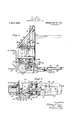
- Figure 1 is a side elevation of a truck embodying my improvements.
- Figure 2 is a top plan view thereof.
- Figure 3 is a front view thereof.
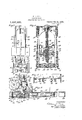
- Figure 4 is a fragmentary transverse vertical section. on an enlarged scale, taken on line 4 4, Fig. 1.
- Figure 5 is an enlarged fragmentary longitudinal section on line 5-5, Fig. 2.
- igure 6 is a fragmentary transverse section of the elevating platform on line 6-6, Fig. 5.
- Figure 7 is an enlarged fragmenta horizontal section on line 7 7, Fig. 1.
- igure 8 is an enlarged fragmentary vertical section on line 8-8, Fig. 2.
- Figure 9 is a transverse section on line 9 9, Fig. 8.
- numeral 15 represents the main frame or wheels 16 are preferably drivenA from an electric moto-r 20 through the medium of a worm and worm wheel, not shown.
- a battery 21 supplies current to the motor which is controlled by a suitable controller 22.
- 23 indicates the operators platform from which position the truck, as well as the elevating platform, is controlled.
- the elevator frame consists of a pair of upright supporting columns 24, 24, which are preferably constructed of channel iron, and which are rigidly Secured at theirl lower ends to the side-channels 19 of the truck frame, while their upper ends are reliably held by diagonal braces 25 and intermediate horizontal braces 26.
- FIG. 27 represents generally the elevating platform ywhich extends forwardly. from the A arranged centrally between the supporting columns 24 and journaled at its lower end in a step bearing 29 formed in the base of a housing or gear case 30, while its upper endl is journaled in a self-alining bearing 31 arranged in the transverse supporting head 32 of said columns.
- This screw is threaded substantially its entire length, its lower end above the step bearing being provided with a squared portion 33 upon which is mounted a worm wheel 34 for turning the screw.
- This worm Wheel is arranged within the housing 30 and meshes with a worm 35 journaled in bearings in said housing.
- an electric motor 36 of the reversible type is preferably provided which transmits motion to said worm by a sprocket chain 37 passing around sprocket wheels 38 and 39 mounted on the motor1 and worm shafts, respectively.
- the housing 30, in which the lower end of the screw 28 is supported, is pivoted ab-out its horizontal transverse axis to provide for misalinement of the screw when the frame is stressed.
- the opposite sides of the housing are provided with trunnions 40 which are journaled in the'adjacent portions of the supporting columns and side channels 19 of the truck fra-me.
- trunnions 40 which are journaled in the'adjacent portions of the supporting columns and side channels 19 of the truck fra-me.
- an arm 41 rovided at its free end with an opening 42.
- l cross piece 43 of the truck frame is a. depending screw or bolt 44 which passes th'rough the opening of said arm and is provided below the latter with stop nuts 45.
- coil spring 46 surrounding the bolt and bearing at its lower end against the arm 41 vand at its upper end against a nut 47 servesl to yieldingly permit the housing 30 to oscillate upwardly and provide for misalinement of the screw should the frame be stressed. rlhe nuts l act as fixed stops and prevent the housing from oscillating below its horizontal plane.
- rollers 49, 50 which are mounted on the outer ends of upper and lower transverse shafts 51 and 52, respectively, carried by said arms.
- rlhe upper' rollers 49 engage the rear flanges of the supporting columns 24, while the lower rollers 50 engage the opposite or ,front fianges of said columns, thereby firmly and reliably supporting the arms on said columns.
- the rollers are provided on their outer sides with flanges 53 which engage the corresponding outer marginal vface of the supporting columns.
- a nut 54 which engages the screw 28 for raising and loweringsaid arms to effect a corresponding movement of the platform 27.
- Thisnut is provided on lopposite sidesthereof with trunnions 5a which are journaled in a yoke 56 supported by trunmons 57 4on" theJ cantilever arms, the trunnions of'said yoke beingarranged at right angles to the trunnionsV of said nut.
- the nut 54 is provided on one side thereof with an oil reservoir or receptacle 58 which is preferably cast integral with said nut, as shown in Fig. 4, and is of the proper depth to contain a sufficient supply of oil forthoroughly lubricating the screw 28.
- rllhis reservoir is separated from the threaded bore of the nut by a partition59, the latter being provided with oil conducting passages 60 which conduct the lubricant from the magazine to the screw.
- Stuffing glands 61 are arranged at the upper and lower ends of the nut for retaining the lubricant therein.
- the oil reservoir is open at its upperl end to permit filling thereof, a suitable cover plate 62'k normally yclosing said opening.
- ⁇ rlhe elevating load platform 27 is supported by the cantilever arms and may be of any. suitable construction. As shown in Figs. 5,- 6 and7, it is constructed of a U-Shaped iron yframe 63 which is open at its rear end to permit the same to overhang the side channels 19 of the frame. 95 A platform plate or support 64 is riveted or otherwise secured to the top of this frame and is reinforced lengthwise thereof by longitudinal channels 65. ln order to permit the platform to tilt upwardly relatively to the cantilever arms should it strike an obstruction in its path yduring the lowering movement thereof, the same is preferably pivoted to said arms. For this purpose,
- pivot plates 66 are mounted on the lower 105 facilitating these operations in an expediv tious manner.
- each cantilever Iarm may loe-provided with av verticallyarranged adjusting bolt 68 which engages the ,underside of the platformplate 64 and per- 120 4mits of uniformly adjusting the platform to different" inclined positions to suit certain working conditions.
- the means for controlling the' elevating motor 36 for raising and. lowering the plat- 125 form 27 together with the means for stopping the latter in any desired position, are
- l' Arranged within a box 69 secured to the rear portion of the truck'frame 15x-isla re- 13e versing' switch 70 of any well known type which is in circuit with the battery 21 and the elevating motor to control the rotation of the screw 28 for raising and lowering the elevating platform.
- the control lever 71 of this switch is connected by a link 72 with one arm of a bell crank lever 73 fulcrumed on the adjacent horizontal brace 26.
- the other arm of this lever is pivotally connected by a link 74 with the lower end of an upright rod or plunger 75 guided at its lower end in a bracket 76 suitably fastened to said horizontal brace.
- This rod which extends substantially to the top of the supporting column 24, is supported at its upper end in a guide bracket 77 suitably secured to the adjacent diagonal brace 25.
- a depending link 78 Connected to the pivot at the lower end of this rod is a depending link 78 which is pivoted at its lower end to a vertically swinging lever 79 fulcrumed on the adjacentl portion of the elevating motor.
- a brake drum 80 Mounted on the shaft 36a of the latter is a brake drum 80 adapted to be engaged by abrake-band 81 constructed of two sections hinged at 82 to the motor frame. The free ends of these sections are provided with ears 85 between which is disposed.
- a rotatable cam-block 84 controlled by the lever 79 and adapted to expand the band for releasing the brake drum.
- a coil spring 85 serves to normally contract the brake band around the drum in the usual manner.
- the switch and brake band 81 are controlled simultaneously by a conveniently located operating handle 86 fulcrumed at 87 and connected by a link 88 with that arm of the bell crank lever to which the link of the switch control lever 71 is connected.
- the operating handle 86 is normall held in its neutral position, as shown by ful lines in Fig. 8, by a centering or return spring 89 which is arralged to be'compressedwhen said handle is moved out of neutral position in either direction of the arrows shown in said figure, and which therefore tends constantly to return the handle to that position when it is unlocked.
- This spring surrounds the rod and is interposed between opposing followers 90 and 91 loosely mounted on this rod and guided in corresponding openings 92 and 93 arranged in upper and lower guide heads or lugs 94, 95, respectively, formed on the bracket 76.
- These followers are adapted to normally seat against the opposing faces 'of the corresponding guide heads.
- a sleeve or abutment 96 Mounted on the rod above the upper follower 90 and held against movement relatively thereto is a sleeve or abutment 96 adapted to abut against said follower to compress the spring 89 downwardly when the operatingy handle is moved forwardly from its neutral position to cause the elevator to be raised; and mounted on the rod below the lower follower 91 is a sleeve or abutment 97 adapted to abut against said follower to compress said spring upwardly" ⁇ j when the operating handle is moved rearable locking mechanism, co-operating with the rod 7 5, is provided which is preferably constructed as follows:
- 98 represents a locking bolt arranged parallel with the upright rod 75 and guided in the bracket 76, said bolt being coupled with said rod by a tie bar 99 so as to move vertically therewith.
- This bolt is provided with upper andl lower locking notches or grooves 100 and 101 with which a spring catch or locking pin 102 is adapted to interlock.
- This catch is preferably arranged in a guide 103 projecting rearwardly fromthe bracket 76.
- the upper end of the rod 75 is provided with an adjustable tappet arm 104 arranged in the path. of one of the rear guide rollers 49 of the arms 48, or other adjacent part thereof.
- this tappet arm Upon striking this tappet arm, the roller forces it from the dotted line position shown in Fig. 8 to the full line position thereof, thereby forcing the rod 75 together with its locking bolt upwardly with it to apply the brake and open the motor switch, and instantly stopping the elevating platform.
- the operating handle is thrown back to neutral position, the spring 89 regulating the return of the same and associated parts to such position.
- the brake actuatingllever 79 is provided with an extension 105 arranged in the path of one of the guide rollers 49 or other adjacent part of the platform, so as to be engaged thereby at a predetermined point and cause the brake to be applied and the motor switch to be opened and thereby in stantly stop the platform.
- this pio extension- may be provided with an adjusting bolt 106 to be engaged by the roller to permit of stopping the Vplatform in various positions.
- This improved Velevating platform truck is easy to operate and very efficienty in operation, affording a great saving of time in handling and moving materials from a lower to ahiglier level and vice versa.
- a truck of the character described the combination with a truck body and a motor mounted thereon, .of an elevator frame carried by said truck body, an elevating platform movable vertically yon said frame, a vertical screw arranged within said frame, a bearing for the lower end of said screw pivotally mounted on said frame, a self-alining bearing for the upper end of said screw, a nutl connected by a universal joint with said platform and engaging said screw, and means driven by said motor for rotating said screw.
- a truck of the character described the combination with a truck body anda motor mounted thereon, of an elevator frame carried by said truck body, a vertically movable platform guided on said frame, means driven by saidv motor for moving said platform, an electric switch included in the circuit of said motor, a brake for said motor, an operating member for manually controlling said switchv and brake, and means operatively connected to said switch, brake and titl operating member for holding said operat- 9.
- a truck of the character described the combination with a truck body and a motor mounted thereon, of an elevator frame carried by said truck body, a vertically movable platform guided on said frame, means driven by said motor for moving said platform, an electric switch included in the circuit of said motor, a brake for said motor, an operating member for manually controlling said switch and brake, means operatively connected to said switch, brake and operating member for holding said operat ing member in its neutral position, and means for retaining said operating member in different operative positions, said platform controlling the movement of said holding means and said retaining means to simultaneously open said'motor switch, apply said brake, and shift said operating member to neutral position.
- a truck of the character described the combination with a truck body and a motor mounted thereon, of an elevator frame carried by said truck body, a vertically movable platform guided on said frame, means driven by said motor for moving said' platform, an electric switch included in the circuit of said motor, a brake for said motor, an operating member for manually controlling said switch and brake, a yieldable member operatively connected to said switch, brake and operating member, and resisting movement of the latter out of its neutral position, and means for retaining said operating member in different operative positions,
- said platform controlling the movement of said yieldable member and said retaining means to simultaneously open said motor switch, apply said brake and shift said operating member to neutral position.
- a truck of the character described the combination with a. truck body and a motor mounted thereon, of an elevator frame carried by said truck body, a vertically movable platform guided on said frame, means driven by said motor for moving said platform, an electric switch in the circuit of said motor, a brake therefor, an operating member for manually controlling said switch and brake, a vertically yieldable member opera- ⁇ tively connected to said switch, brake and operating member and resisting movement of the latter out of its neutral position, a locking bolt movable with said yieldable member, a spring catch arranged to interlock with said bolt for retaining said operating member in different operative positions, said platform controlling the movement of said yieldable member to simultaneously open said switch, apply said bralre and shift said operating member to neutral position.
- a truck of the character described the combination with a truck Body and a motor mounted thereon, of an elevator frame carried by said truck body, 'a vertically movable platform guided on said frame, means driven by said motor for moving said platform, an electric switch in the circuit of said motor, a brake therefor, an operating member for manually controlling said switch and brake, a vertically movable member extending substantially the length of said elevator frame and operatively connected to said switch, bralre and operating member, means for locking the latter in diiferent operative positions, a spring for resisting movement of said operating member out of its neutral position, and means arranged at the upper and lower ends of said vertically movable member and actuated by said elevator platform to cause said member to be moved in the proper directionto shift said operating member to neutral position.
- a bellcranlr lever having one arm connected to said switch and the other arm connected to said brake, and an 'l0 operating handle connected to said lever for simultaneously I actuating said switch and brake.
- bralre for said motor, a bell cranlr lever having one arm connected to said switch and the other arm connected to said brake, an operating handle connected to said lever for simultaneously actuating said switch and. brake,
- nei-omen a yieldable member operatively connected to said bell crank lever and resisting movement of the operating handle out of its neutral position, and means 'for retaining said operating handle in'ditlerent operative positions.
- a vertically movable elevating platform a screw, means for rotating said screw, a nut mounted on said platform and engaging said screw, and an oil reservoir formed in thev body of the nut and communicating with the screw.
Description
fw. c. CARR.
ELEvA'ToR IRUCK.
APPLICATION FILED AUG 24, 1920.
Patented Feb. 21, 1922.
M 3 SHEETS-SHEET l.
W. C. CARR.
ELEVATOR TRUCK.'A AFPLvlcATloN FILED M1624, 1920.
1,407,124. Patented Febyzl, 1922.
3 WENS-'SHEET 2.
` W. C. CARR. vELEVATOR TRUCK.
v APPLICATION FILED AUG. 24.. |920. 1,407,124, Patented Feb. 21, 1922.
3 SHEETS-SHEET 3- para sra WILLAM C. CARR, OF BUFFALO, NEW YORK.
ELEVATOR TRUCK.
Specification of Letters ?atent.
Patented Feb. 21, 11922.
Application led August 24, 1920. Serial No. 405,695.
Zo all whom t may concern.'
Be it known that I, WILLIAM C. CARR, a citizen of the United States, residing at Buffalo, in the county of Erie and State of New York, have invented new and useful Improvements in Elevator Trucks, of which the following is a specification.
This invention relates to trucks and more particularly to that type of trucks which are used for transportation purposes, as well as raising and lowering their load platforms fromV one position to another to facilitate loading and unloading thereof.
The prinicpal object of this invention is the provision of an im roved electricallycontrolled elevating plat orm for such trucks for lifting or tiering the load from a lower to a higher level or vice versa.
Other objects are to provide an elevating platform of this character which is simple,`
strong and durable in construction, which is eiicient in operation, and which is conveniently controlled from the operators platform.
A further object of the invention is to provide a brake in conjunction with the elevating mechanism for stopping the platform instantly in any desired position.
A still further object is the provision of automatic mea-ns for stopping the elevating platform when it reaches t-he end of its pre'- determined travel. p
Other objects are to provide certain novel details of construction which will 'be fully hereinafter described and claimed.
In the accompanying drawings:
Figure 1 is a side elevation of a truck embodying my improvements. Figure 2 is a top plan view thereof. Figure 3 is a front view thereof. Figure 4 is a fragmentary transverse vertical section. on an enlarged scale, taken on line 4 4, Fig. 1. Figure 5 is an enlarged fragmentary longitudinal section on line 5-5, Fig. 2. igure 6 is a fragmentary transverse section of the elevating platform on line 6-6, Fig. 5. Figure 7 is an enlarged fragmenta horizontal section on line 7 7, Fig. 1. igure 8 is an enlarged fragmentary vertical section on line 8-8, Fig. 2. Figure 9 is a transverse section on line 9 9, Fig. 8.
Similar characters of reference 4indicate corresponding parts throughout the several views.
lf have shown my invention applied to a motor propelled truck, although it is appli- I cable to other types of trucks as well. The
The elevator frame consists of a pair of upright supporting columns 24, 24, which are preferably constructed of channel iron, and which are rigidly Secured at theirl lower ends to the side-channels 19 of the truck frame, while their upper ends are reliably held by diagonal braces 25 and intermediate horizontal braces 26.
27 represents generally the elevating platform ywhich extends forwardly. from the A arranged centrally between the supporting columns 24 and journaled at its lower end in a step bearing 29 formed in the base of a housing or gear case 30, while its upper endl is journaled in a self-alining bearing 31 arranged in the transverse supporting head 32 of said columns. This screw is threaded substantially its entire length, its lower end above the step bearing being provided with a squared portion 33 upon which is mounted a worm wheel 34 for turning the screw. This worm Wheel is arranged within the housing 30 and meshes with a worm 35 journaled in bearings in said housing. Any suitable means may be employed for rotating the worm to drive the screw in either direction, but as shown in the drawings, an electric motor 36 of the reversible type is preferably provided which transmits motion to said worm by a sprocket chain 37 passing around sprocket wheels 38 and 39 mounted on the motor1 and worm shafts, respectively.
As shown in Figs. 4 and 5, the housing 30, in which the lower end of the screw 28 is supported, is pivoted ab-out its horizontal transverse axis to provide for misalinement of the screw when the frame is stressed. For this purpose, the opposite sides of the housing are provided with trunnions 40 which are journaled in the'adjacent portions of the supporting columns and side channels 19 of the truck fra-me.- Extending rearwardly from the housing is an arm 41 rovided at its free end with an opening 42. l cross piece 43 of the truck frame is a. depending screw or bolt 44 which passes th'rough the opening of said arm and is provided below the latter with stop nuts 45. A
48, 48 represent a pair of cantilever arms or supporting members which are guided' on the supporting columns and. which serve to support the elevating platform 27. rlloe preferred means for guiding these arms consists of two sets of rollers 49, 50 which are mounted on the outer ends of upper and lower transverse shafts 51 and 52, respectively, carried by said arms. rlhe upper' rollers 49 engage the rear flanges of the supporting columns 24, while the lower rollers 50 engage the opposite or ,front fianges of said columns, thereby firmly and reliably supporting the arms on said columns.v 'llo prevent these arms from swaying laterally, the rollers are provided on their outer sides with flanges 53 which engage the corresponding outer marginal vface of the supporting columns. f
Mounted for universal movement between the upright rear portions of the cantilever arms 48 is a nut 54 which engages the screw 28 for raising and loweringsaid arms to effect a corresponding movement of the platform 27. Thisnut is provided on lopposite sidesthereof with trunnions 5a which are journaled in a yoke 56 supported by trunmons 57 4on" theJ cantilever arms, the trunnions of'said yoke beingarranged at right angles to the trunnionsV of said nut. Bythus universally` supporting the latter, it can' readily accommodate-itself to any tilting action or disalinem'entf of the screw due to stresses imposed on-'the truck body and elevator frame.
ecured in the By pivotally mounting the lower end of the screw and providing its upper end wlth a self-alining bearing, as shown, together with the universally jointed nut co-operatlng with said screw, binding or breakage of the parts is prevented, and uniform running is assured under all conditions.
The nut 54 is provided on one side thereof with an oil reservoir or receptacle 58 which is preferably cast integral with said nut, as shown in Fig. 4, and is of the proper depth to contain a sufficient supply of oil forthoroughly lubricating the screw 28. rllhis reservoir is separated from the threaded bore of the nut by a partition59, the latter being provided with oil conducting passages 60 which conduct the lubricant from the magazine to the screw. Stuffing glands 61 are arranged at the upper and lower ends of the nut for retaining the lubricant therein. The oil reservoir is open at its upperl end to permit filling thereof, a suitable cover plate 62'k normally yclosing said opening.
`rlhe elevating load platform 27, as previously noted, is supported by the cantilever arms and may be of any. suitable construction. As shown in Figs. 5,- 6 and7, it is constructed of a U-Shaped iron yframe 63 which is open at its rear end to permit the same to overhang the side channels 19 of the frame. 95 A platform plate or support 64 is riveted or otherwise secured to the top of this frame and is reinforced lengthwise thereof by longitudinal channels 65. ln order to permit the platform to tilt upwardly relatively to the cantilever arms should it strike an obstruction in its path yduring the lowering movement thereof, the same is preferably pivoted to said arms. For this purpose,
The extreme .front end of each cantilever Iarm may loe-provided with av verticallyarranged adjusting bolt 68 which engages the ,underside of the platformplate 64 and per- 120 4mits of uniformly adjusting the platform to different" inclined positions to suit certain working conditions.
The means for controlling the' elevating motor 36 for raising and. lowering the plat- 125 form 27 together with the means for stopping the latter in any desired position, are
preferably constructed as follows: l' Arranged within a box 69 secured to the rear portion of the truck'frame 15x-isla re- 13e versing' switch 70 of any well known type which is in circuit with the battery 21 and the elevating motor to control the rotation of the screw 28 for raising and lowering the elevating platform. The control lever 71 of this switch is connected by a link 72 with one arm of a bell crank lever 73 fulcrumed on the adjacent horizontal brace 26. The other arm of this lever is pivotally connected by a link 74 with the lower end of an upright rod or plunger 75 guided at its lower end in a bracket 76 suitably fastened to said horizontal brace. This rod, which extends substantially to the top of the supporting column 24, is supported at its upper end in a guide bracket 77 suitably secured to the adjacent diagonal brace 25. Connected to the pivot at the lower end of this rod is a depending link 78 which is pivoted at its lower end to a vertically swinging lever 79 fulcrumed on the adjacentl portion of the elevating motor. Mounted on the shaft 36a of the latter is a brake drum 80 adapted to be engaged by abrake-band 81 constructed of two sections hinged at 82 to the motor frame. The free ends of these sections are provided with ears 85 between which is disposed. a rotatable cam-block 84 controlled by the lever 79 and adapted to expand the band for releasing the brake drum. A coil spring 85 serves to normally contract the brake band around the drum in the usual manner. The switch and brake band 81 are controlled simultaneously by a conveniently located operating handle 86 fulcrumed at 87 and connected by a link 88 with that arm of the bell crank lever to which the link of the switch control lever 71 is connected. By this arrangement of the parts, it is possible to instantly stop the elevating platform in any desired position, inasmuch as the motor switch and brake `are actuated simultaneously by a single movement of the operating handle.
The operating handle 86 is normall held in its neutral position, as shown by ful lines in Fig. 8, by a centering or return spring 89 which is arralged to be'compressedwhen said handle is moved out of neutral position in either direction of the arrows shown in said figure, and which therefore tends constantly to return the handle to that position when it is unlocked. This spring surrounds the rod and is interposed between opposing followers 90 and 91 loosely mounted on this rod and guided in corresponding openings 92 and 93 arranged in upper and lower guide heads or lugs 94, 95, respectively, formed on the bracket 76. These followers are adapted to normally seat against the opposing faces 'of the corresponding guide heads. Mounted on the rod above the upper follower 90 and held against movement relatively thereto is a sleeve or abutment 96 adapted to abut against said follower to compress the spring 89 downwardly when the operatingy handle is moved forwardly from its neutral position to cause the elevator to be raised; and mounted on the rod below the lower follower 91 is a sleeve or abutment 97 adapted to abut against said follower to compress said spring upwardly"` j when the operating handle is moved rearable locking mechanism, co-operating with the rod 7 5, is provided which is preferably constructed as follows:
98 represents a locking bolt arranged parallel with the upright rod 75 and guided in the bracket 76, said bolt being coupled with said rod by a tie bar 99 so as to move vertically therewith. This bolt is provided with upper andl lower locking notches or grooves 100 and 101 with which a spring catch or locking pin 102 is adapted to interlock. This catch is preferably arranged in a guide 103 projecting rearwardly fromthe bracket 76. Thus, when the operating handle is moved forwardly to raise the elevating platform, the brake'control rod is lowered, moving the locking bolt with it and allowing the spring catch to interlock with the upper notch 100 of said bolt to reliably hold the same in position during the raising of said platform. j g
To automatically stop the elevating platform when it reaches its highest position without requiring the attention of the operator, the upper end of the rod 75 is provided with an adjustable tappet arm 104 arranged in the path. of one of the rear guide rollers 49 of the arms 48, or other adjacent part thereof. Upon striking this tappet arm, the roller forces it from the dotted line position shown in Fig. 8 to the full line position thereof, thereby forcing the rod 75 together with its locking bolt upwardly with it to apply the brake and open the motor switch, and instantly stopping the elevating platform. Simultaneously with this movenient, the operating handle is thrown back to neutral position, the spring 89 regulating the return of the same and associated parts to such position. Likewise, provision is made for stopping the platform when 1t reaches its lowest position. As shown in Fig. 8, the brake actuatingllever 79 is provided with an extension 105 arranged in the path of one of the guide rollers 49 or other adjacent part of the platform, so as to be engaged thereby at a predetermined point and cause the brake to be applied and the motor switch to be opened and thereby in stantly stop the platform. If desired, this pio extension-may be provided with an adjusting bolt 106 to be engaged by the roller to permit of stopping the Vplatform in various positions.
,lin the operation of this apparatus, assuming the parts to be in their normal posi- ,tion shown by full lines in the drawings, \and it is desired to elevate the load platform to\ the dotted linelposition shown in F ig. 1, the operating handle 86 is moved forward to the position shown by dotted lines in Fig. 8. This movement, as previously described, releases the elevating motor brake and closes the .motor switch, thereby rotating the screw 28 in the proper direction to elevate the platform, the spring 89 being compressed and the spring catch engaging the upper notch in the locking bolt 98. l Should vit be desired to stop the platform before reaching its highest position, the operator simply returns the Operating handle to neutral position, which movement applies the brake and opens the motor switch, bringing the platform to an instant stop. However, should it be desired to allow the platform to be elevated to its highest position, it is not necessary that the operator move the handle to restore the parts' to neutral position, this being done automatically, as previously described. l effected by moving the handle rearwardly, and when it reaches its lowest position it is automatically stopped. ,f
This improved Velevating platform truck is easy to operate and very efficienty in operation, affording a great saving of time in handling and moving materials from a lower to ahiglier level and vice versa.
li claim as my invention:
1. lin a truck of the/character described, the combination with a` truck lbody and a motor mounted thereon, of an elevator frame carried by said truck body, a screw arranged within said frame, a bearing for the lower end of said screw, pivotally mounted on said frame, a self-alining bearing for the upper end of said screw, an elevating platform guided on said frame and operatively connected to said screw, and means driven by saidmotor for 'rotating said screw. v
' 2. fn a truck of the character described,'.
the combination with a truck body and a motor mounted thereon, of an elevator frame carried by said truck body, an elevating'platform vmovable vertically on said frame, a-
'llhe lowering of the platform is anomali screw arranged within said frame, a pivoted bearing member for the lower end of said screw, a nut'conn'ected by a universal joint with said platform and engaging said screw, and means driven by' said motor for rotating said screw. r Y
t. ln a truck of the character described, the combination with a truck body and a motor mounted thereon, .of an elevator frame carried by said truck body, an elevating platform movable vertically yon said frame, a vertical screw arranged within said frame, a bearing for the lower end of said screw pivotally mounted on said frame, a self-alining bearing for the upper end of said screw, a nutl connected by a universal joint with said platform and engaging said screw, and means driven by said motor for rotating said screw.
' 5. ln a truck of the character described,
the combination with a truck body and a motor mounted thereon, of an elevator rame carried by said truck body, a vertical screw arranged in said frame, a bearing for the lower end of said screw pivotally mounted on said frame, a self alining bearingl for the upper end of said screw, a yieldable connection between said pivoted bearing and said truck body to provide for oscillatory movement of said bearing relatively to said body, a vertically movable platform operatively connected to said screw, and means driven by lsaid motor for rotating said screw.
6. lin a truck of the character described, the combination with a truck body and a motor mounted thereon, of an elevator frame carried by said truck-body, a supportingv member guided on said frame, an elevating platform hinged to said member to swing upwardly thereon and means driven by said motor for vertically moving said member.
7. lin a truck of the character described, the combination with a truck body and a motor mounted thereon, of an elevator frame carried by said truck body, a supporting member guided on said frame, an elevating platform hinged to said member to swing upwardly thereon, adjusting means mounted on said supporting member and engaging said platform for regulating the inclination thereof, and means driven by said motor for vertically moving said member.
8. ln a truck of the character described, the combination with a truck body anda motor mounted thereon, of an elevator frame carried by said truck body, a vertically movable platform guided on said frame, means driven by saidv motor for moving said platform, an electric switch included in the circuit of said motor, a brake for said motor, an operating member for manually controlling said switchv and brake, and means operatively connected to said switch, brake and titl operating member for holding said operat- 9. In a truck of the character described, the combination with a truck body and a motor mounted thereon, of an elevator frame carried by said truck body, a vertically movable platform guided on said frame, means driven by said motor for moving said platform, an electric switch included in the circuit of said motor, a brake for said motor, an operating member for manually controlling said switch and brake, means operatively connected to said switch, brake and operating member for holding said operat ing member in its neutral position, and means for retaining said operating member in different operative positions, said platform controlling the movement of said holding means and said retaining means to simultaneously open said'motor switch, apply said brake, and shift said operating member to neutral position.
l0. ln a truck of the character described, the combination with a truck body and a motor mounted thereon, of an elevator frame carried by said truck body, a vertically movable platform guided on said frame, means driven by said motor for moving said' platform, an electric switch included in the circuit of said motor, a brake for said motor, an operating member for manually controlling said switch and brake, a yieldable member operatively connected to said switch, brake and operating member, and resisting movement of the latter out of its neutral position, and means for retaining said operating member in different operative positions,
said platform controlling the movement of said yieldable member and said retaining means to simultaneously open said motor switch, apply said brake and shift said operating member to neutral position.
1l. In a truck of the character described, the combination with a truck body and a motor mounted thereon, of an elevator frame carried by said body, a' vertically movable platform guided on said frame, means driven by said motor for moving said platform, an electric switch included in the circuit of said motor, a brake for said motor, an operating handle controlling said switch and brake, a yieldable member operatively connected to said switch brake and operating member and resisting movement of the latter out of its neutral working position, and a locking bolt for said yieldable member for retaining said operating member in different operative positions, said platform controlling the movement of said yieldable member ,to simultaneously open said switch, apply said brake, and shift said operating member to` neutral position.v
l2. In. a truck of the character described, the combination with a. truck body and a motor mounted thereon, of an elevator frame carried by said truck body, a vertically movable platform guided on said frame, means driven by said motor for moving said platform, an electric switch in the circuit of said motor, a brake therefor, an operating member for manually controlling said switch and brake, a vertically yieldable member opera-` tively connected to said switch, brake and operating member and resisting movement of the latter out of its neutral position, a locking bolt movable with said yieldable member, a spring catch arranged to interlock with said bolt for retaining said operating member in different operative positions, said platform controlling the movement of said yieldable member to simultaneously open said switch, apply said bralre and shift said operating member to neutral position.
13. ln a truck of the character described, the combination with a truck Body and a motor mounted thereon, of an elevator frame carried by said truck body, 'a vertically movable platform guided on said frame, means driven by said motor for moving said platform, an electric switch in the circuit of said motor, a brake therefor, an operating member for manually controlling said switch and brake, a vertically movable member extending substantially the length of said elevator frame and operatively connected to said switch, bralre and operating member, means for locking the latter in diiferent operative positions, a spring for resisting movement of said operating member out of its neutral position, and means arranged at the upper and lower ends of said vertically movable member and actuated by said elevator platform to cause said member to be moved in the proper directionto shift said operating member to neutral position.,
lll. ln a truck of the character described,
the combination with a truck body and a motor mounted thereon, of an elevator frame carried by said truck body, a vertically movable elevator guided on said frame, means driven by said motor for moving'said platform, an electric switch in the circuit of said motor, a brake for said motor, an operating member for manually controlling said switch and brake, and movable to different operative positions, and automatic means controlled by said platform for opening'said switch, applying said brake and shifting said operating member toneutral position comprising an upright rod, means for supporting said rod and having upper and lower guide heads, followers guided on said rod and normally abutting against said heads, a
spring interposed between said followers,`
abutments mounted on said rod and engaging the outer ends of said followers, rappets mounted on either end of said upright rod and in the path of movement of said platform, and connections from said rod to said switch, brake and operating member.
15. ln a truck of the character described, 13e
6 said motor for moving said platform, an
electric switch in the circuit or the motor, a
brake for said motor, a bellcranlr lever having one arm connected to said switch and the other arm connected to said brake, and an 'l0 operating handle connected to said lever for simultaneously I actuating said switch and brake.
16. lln a truck ot the character described, the combination with a truck. body and a 'le lmotor mounted thereon, of an elevator :trame carried by said truck bodi a movable elevator guided on said trame, means driven by said motor for moving said plattform, an electric switch in the circuit of said motor, a
.20 bralre for said motor, a bell cranlr lever having one arm connected to said switch and the other arm connected to said brake, an operating handle connected to said lever for simultaneously actuating said switch and. brake,
25 and a yieldable member operatively connected to said bell cranlr lever and resisting movement oi the operatlng handle out oi its neuy, tral position.-
l?. ln a truclr or the character described,
t@ the combination with a truck body and a motor mounted thereon, of an elevator frame carried by said truck body, a `movable elevator guided .on said trame, means driven by said motor for moving said platform, an
85 electric switch in the circuit of said motor, a
brake tor said motor, a bell cranlr lever having one arm connected to said switch and the other arm connected to -said brake, an operating handle connected to said lever for simul- 4@ taneously actuating said switch and brake,`
nei-omen a yieldable member operatively connected to said bell crank lever and resisting movement of the operating handle out of its neutral position, and means 'for retaining said operating handle in'ditlerent operative positions.,
18. lin a truck of the character described,
the combination with a truck body and a motor mounted thereon, of an elevator frame carried by said truck body, a movable elevator guided on said frame, means driven by said motor for moving said platform, an electric switch in the circuit of said motor, a brake for said motor, a bell crank lever 'having one arm connected to said switch and the other 'arm connected to said brake, an
operating handle connected to said lever for J simultaneously actuating said switch and bralre, a vertically movable member operatively connected to said bell crank lever, tappets arranged at the upper and lower ends of said member and in the path of said elevator, and yieldable means i'or resisting movement of said movable member in either direction.
19. ln a vertically movable elevating platform, a screw, means for rotating said screw, a nut mounted on said platform and engaging said screw, and an oil reservoir formed in thev body of the nut and communicating with the screw..
20. lin a vertically movable elevating platform, a screw, means for rotating said screw, a nut mounted on said platform and engaging said screw, an oil reserver formed in the body of the nut, and a partition separating said reservoir from the threaded bore ot the nut and provided with oil conduct-ing pas.
sages.
wrnrrav c. cana
Priority Applications (1)
| Application Number | Priority Date | Filing Date | Title |
|---|---|---|---|
| US405695A US1407124A (en) | 1920-08-24 | 1920-08-24 | Elevator truck |
Applications Claiming Priority (1)
| Application Number | Priority Date | Filing Date | Title |
|---|---|---|---|
| US405695A US1407124A (en) | 1920-08-24 | 1920-08-24 | Elevator truck |
Publications (1)
| Publication Number | Publication Date |
|---|---|
| US1407124A true US1407124A (en) | 1922-02-21 |
Family
ID=23604817
Family Applications (1)
| Application Number | Title | Priority Date | Filing Date |
|---|---|---|---|
| US405695A Expired - Lifetime US1407124A (en) | 1920-08-24 | 1920-08-24 | Elevator truck |
Country Status (1)
| Country | Link |
|---|---|
| US (1) | US1407124A (en) |
Cited By (9)
| Publication number | Priority date | Publication date | Assignee | Title |
|---|---|---|---|---|
| US2482211A (en) * | 1942-12-21 | 1949-09-20 | Reichardt Hendricus Cornelis | Lifting apparatus |
| US2635771A (en) * | 1950-01-17 | 1953-04-21 | Kroger Co | Elevator apparatus for vehicles |
| US2818156A (en) * | 1954-08-13 | 1957-12-31 | Coca Cola Bottling Works Compa | Pallet moving device |
| US3272286A (en) * | 1964-08-24 | 1966-09-13 | Philip A Leduc | Portable elevating mechanism |
| US5293963A (en) * | 1992-03-26 | 1994-03-15 | Linde Aktiengesellschaft | Forklift truck |
| US5368130A (en) * | 1993-11-15 | 1994-11-29 | Savage Bros. Co. | Lift truck |
| US5752584A (en) * | 1995-04-03 | 1998-05-19 | Crown Equipment Corporation | Auxiliary lifting forks for double-length pallet trucks |
| US5878844A (en) * | 1996-11-12 | 1999-03-09 | Hk Systems, Inc. | Ball screw joint for an automated guided vehicle |
| US20120012425A1 (en) * | 2009-01-23 | 2012-01-19 | Isao Hayase | Linear actuator and forklift truck |
-
1920
- 1920-08-24 US US405695A patent/US1407124A/en not_active Expired - Lifetime
Cited By (9)
| Publication number | Priority date | Publication date | Assignee | Title |
|---|---|---|---|---|
| US2482211A (en) * | 1942-12-21 | 1949-09-20 | Reichardt Hendricus Cornelis | Lifting apparatus |
| US2635771A (en) * | 1950-01-17 | 1953-04-21 | Kroger Co | Elevator apparatus for vehicles |
| US2818156A (en) * | 1954-08-13 | 1957-12-31 | Coca Cola Bottling Works Compa | Pallet moving device |
| US3272286A (en) * | 1964-08-24 | 1966-09-13 | Philip A Leduc | Portable elevating mechanism |
| US5293963A (en) * | 1992-03-26 | 1994-03-15 | Linde Aktiengesellschaft | Forklift truck |
| US5368130A (en) * | 1993-11-15 | 1994-11-29 | Savage Bros. Co. | Lift truck |
| US5752584A (en) * | 1995-04-03 | 1998-05-19 | Crown Equipment Corporation | Auxiliary lifting forks for double-length pallet trucks |
| US5878844A (en) * | 1996-11-12 | 1999-03-09 | Hk Systems, Inc. | Ball screw joint for an automated guided vehicle |
| US20120012425A1 (en) * | 2009-01-23 | 2012-01-19 | Isao Hayase | Linear actuator and forklift truck |
Similar Documents
| Publication | Publication Date | Title |
|---|---|---|
| US4287959A (en) | Self propelled pallet truck | |
| US2410373A (en) | Revolving crane accessory for fork trucks | |
| US2564002A (en) | Power-driven material handling truck | |
| US2399605A (en) | Motorized lift truck | |
| US2596477A (en) | Lift truck grab arm mechanism for cylindrical bodies | |
| US2475963A (en) | Motor truck crane | |
| US1407124A (en) | Elevator truck | |
| US3202233A (en) | Pallet or stillage trucks | |
| US2867409A (en) | Service jack | |
| US2126289A (en) | Lifting truck | |
| US2601171A (en) | Power propelled truck of the type provided with a steering handle connected to a swiveled traction wheel | |
| US2298196A (en) | Load transporting, slewing, and tiering device | |
| US2690272A (en) | Rotating load platform for lift trucks | |
| US2494505A (en) | Stabilized load-lifting power-actuated truck | |
| US2216697A (en) | Industrial truck | |
| US3181640A (en) | Industrial trucks | |
| US2623653A (en) | Tilting and traction assembly for industrial trucks | |
| US2407012A (en) | Safety device for dump trucks | |
| US2251435A (en) | Tipping vehicle | |
| US3257011A (en) | Tail gate loading apparatus | |
| US2306055A (en) | Soaking pit crane | |
| US2254331A (en) | Lift truck | |
| US1874189A (en) | Hoisting apparatus for roadway vehicles | |
| US1424788A (en) | Electric truck | |
| US2878884A (en) | Front wheel drive tow tractor |