US1663120A - Pad holder - Google Patents
Pad holder Download PDFInfo
- Publication number
- US1663120A US1663120A US102155A US10215526A US1663120A US 1663120 A US1663120 A US 1663120A US 102155 A US102155 A US 102155A US 10215526 A US10215526 A US 10215526A US 1663120 A US1663120 A US 1663120A
- Authority
- US
- United States
- Prior art keywords
- holder
- pad
- apron
- cover
- screws
- Prior art date
- Legal status (The legal status is an assumption and is not a legal conclusion. Google has not performed a legal analysis and makes no representation as to the accuracy of the status listed.)
- Expired - Lifetime
Links
Images
Classifications
-
- B—PERFORMING OPERATIONS; TRANSPORTING
- B43—WRITING OR DRAWING IMPLEMENTS; BUREAU ACCESSORIES
- B43K—IMPLEMENTS FOR WRITING OR DRAWING
- B43K23/00—Holders or connectors for writing implements; Means for protecting the writing-points
- B43K23/001—Supporting means
Definitions
- This invention relates to pad holders and covers and has as one of its objects to provide a pad holder that is more particularly adapted for auto-logging.
- Another object of this invention is to provide a pad holder having a novel means of support.
- a further object of this invention is to provide a pad holder combining a pencil holder with its supporting means.
- a further object of this invention is to provide a pad holder having a cover to protect the contents.
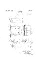
- Fig. 1 is a side elevation of the holder
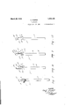
- Fig. 2 is a side elevation of a fragment of the holder showing the cover partly inserted;
- Fig. 3 is a side elevation of a fragment of the holder showing the cover fully inserted to place;
- Fig. 4 is a perspective view of'a fragment of the cover
- Fig. 5 is a front elevation of the holder with the cover removed
- Fig. 6 is a rear elevation of a fragment of the holder showing the supporting means:
- Figs. 7 8, 9 and 10 show modified forms of the holder.
- the numeral 1 refers to the pad holder which consists of a body portion 2, comprising a back 3, sides 4, a bottom 5 and inwardly turned edges 6, the bottom, sides and edges being formed integral with said back and on the three sides respectively, of the body portion 2 in a manner to stiffen the body and to accommodate a pad 7 or other uniformly cut papers.
- a portion 8 In continuation of the back and extending upward therefrom is a portion 8, that projects above the sides 4 in a manner to afford thereto a certain flexibility, for a purpose to be explained, and this portion is bent backward upon itself to form a depending apron I
- the bend in the portion 8 may be circular, as at 10, and designed to hold a pencil 11, in which case the circular part will be provided with a slight tension whereby the pencil will be secured against accidental removal, and the apron 9, is bent outward and away from the back, and at a slight angle thereto,
- slots 13 being provided in the apron for the purpose and to receive the screws and thus support the holder.
- the apron may have its lower edge turned inward if desired to form a raised portion 14, and this raised portion may be utilized to act to prevent the apron becoming accidently disengaged from the screws, by affording a stop against which they will strike even though the vibration of the car move the apron up on the, screws against the friction of the apron and the back.
- the stop will engage that part of the. screw heads that projects over the edges of the slots, and the yielding nature of the apron will cause it to hug the heads ofthe screws, and thus direct the screws to contact the stop should a normal upward movement occur.
- a cover 15 is provided.
- the cover consists preferably of a face plate 16, designed for sliding reception in the inwardly turned edges 6 of the body, and
- a block 17 may carry a block 17 or have a turned edge 17 as shown in Figs. 8, 9 and 10, on one of its ends to yieldingly contact the portion 8 of the body.
- cover may be constructed of paper, that would require a block 17 to cover the top of the pad as shown, it is obvious that a metal slide may be provided that may be formed to provide a face 18 that is ofiset from the face plate to engage the portion 8, and in this case the formed portion may be made circular, as at 19, as and for the purpose described for the circle 10.
- the pad (01' sheets) is preferably ruled to, provide for a log, and during travel the holder may be readily removed manually from the screws as above explained, when it will form a substantial and convenient article upon which to' write a log of travel, the cover obviously being partly removed for accessibility to the pad, and the pencil being readily accessible for use.
- the design shown may also be used without a cover,'t-he' apronheing on the reverse side for the purpose, and to bring the pad from the holder, the extended portion being provided with screw engaging-slots and bent back upon itself to form; an apron,said apron being adapted to provide a yielding securing means for said holder.
- said apron beingadapted to provide a: yielding securing means for said holder.
Description
March 20, 1928.
C. COSPER PAD HOLDER Filed April 15. 1926 2 Sheets-Sheet 1 9mm (262/ @J z/ W h mm Patented Mar. 20, 1928.
CECIL COSPER, WALLA WALLA, WASHINGTON.
PAD HOLDER.
Application filed April 15, 1926. Serial No. 102,155.
This invention relates to pad holders and covers and has as one of its objects to provide a pad holder that is more particularly adapted for auto-logging.
Another object of this invention is to provide a pad holder having a novel means of support.
A further object of this invention is to provide a pad holder combining a pencil holder with its supporting means.
A further object of this invention is to provide a pad holder having a cover to protect the contents.
WVith these and other objects in view reference is now had to the accompanying drawings in which Fig. 1 is a side elevation of the holder;
Fig. 2 is a side elevation of a fragment of the holder showing the cover partly inserted;
Fig. 3 is a side elevation of a fragment of the holder showing the cover fully inserted to place;
Fig. 4 is a perspective view of'a fragment of the cover;
Fig. 5 is a front elevation of the holder with the cover removed;
Fig. 6 is a rear elevation of a fragment of the holder showing the supporting means: and
Figs. 7 8, 9 and 10, show modified forms of the holder.
Having reference to the drawings like numerals refer to like parts throughout the several views and the numeral 1 refers to the pad holder which consists of a body portion 2, comprising a back 3, sides 4, a bottom 5 and inwardly turned edges 6, the bottom, sides and edges being formed integral with said back and on the three sides respectively, of the body portion 2 in a manner to stiffen the body and to accommodate a pad 7 or other uniformly cut papers.
In continuation of the back and extending upward therefrom is a portion 8, that projects above the sides 4 in a manner to afford thereto a certain flexibility, for a purpose to be explained, and this portion is bent backward upon itself to form a depending apron I The bend in the portion 8 may be circular, as at 10, and designed to hold a pencil 11, in which case the circular part will be provided with a slight tension whereby the pencil will be secured against accidental removal, and the apron 9, is bent outward and away from the back, and at a slight angle thereto,
to readily admit of screwheads 12, between the apron and the back and to frictionally secure said screwheads therebetween, slots 13 being provided in the apron for the purpose and to receive the screws and thus support the holder.
The apron may have its lower edge turned inward if desired to form a raised portion 14, and this raised portion may be utilized to act to prevent the apron becoming accidently disengaged from the screws, by affording a stop against which they will strike even though the vibration of the car move the apron up on the, screws against the friction of the apron and the back.
Thus by providing the raised portion 1a on the apron, to form a stop, the stop will engage that part of the. screw heads that projects over the edges of the slots, and the yielding nature of the apron will cause it to hug the heads ofthe screws, and thus direct the screws to contact the stop should a normal upward movement occur.
Hence should the apron assume the upward position (overcoming the resistance due to the yielding pressure of the apron against the screw heads in so doing) until the screws reach the lower extremity of the slots, the stop will interfere and prevent the screw heads passing completely out of the slots, until the securing means thus formed is properly manipulated by sliding the holder upward and at the same time pressing the apron inward, to permit the passage of the heads past the raised portion.
To prevent an undue amount of dust to come in contact with the sheets of the pad 7 a cover 15 is provided.
The cover consists preferably of a face plate 16, designed for sliding reception in the inwardly turned edges 6 of the body, and
may carry a block 17 or have a turned edge 17 as shown in Figs. 8, 9 and 10, on one of its ends to yieldingly contact the portion 8 of the body.
While the cover may be constructed of paper, that would require a block 17 to cover the top of the pad as shown, it is obvious that a metal slide may be provided that may be formed to provide a face 18 that is ofiset from the face plate to engage the portion 8, and in this case the formed portion may be made circular, as at 19, as and for the purpose described for the circle 10.
In use screws, or nails, or the like, are inserted in a convenient place to support the holder, and the holder is then secured thereon by means of the slottedjapron.
The pad is now inserted in the inwardly turned edges and the face plate of the cover is inserted between the edges and the" pad, and when in the closed position the block will rest against the portion 8, as above explained, and on the top of the pad.-
The insertion of a pencil in the circle now completes the assembly.
Asthe holder is primarily for automobile use, the pad (01' sheets) is preferably ruled to, provide for a log, and during travel the holder may be readily removed manually from the screws as above explained, when it will form a substantial and convenient article upon which to' write a log of travel, the cover obviously being partly removed for accessibility to the pad, and the pencil being readily accessible for use.
As soon as the record is made the cover is replaced and the holder restored to its screws, and in this manner and by this means a complete record may be kept of a trip, and the record maintained free of dust.
The design shown may also be used without a cover,'t-he' apronheing on the reverse side for the purpose, and to bring the pad from the holder, the extended portion being provided with screw engaging-slots and bent back upon itself to form; an apron,said apron being adapted to provide a yielding securing means for said holder. I p
2. In a pad holder, the combination with a body portion, and a detachable cover therefor, of a. back extended upward from'the holder, the extended portion being provided" with screw engaging slots, and bent back upon itself to form an-aprornan edge turnedon said apron and positioned to engage the;
screws under certain conditions, and said apron beingadapted to provide a: yielding securing means for said holder.
In testimony whereof I aflix my slgnature.
CECIL o'osPER.
Priority Applications (1)
| Application Number | Priority Date | Filing Date | Title |
|---|---|---|---|
| US102155A US1663120A (en) | 1926-04-15 | 1926-04-15 | Pad holder |
Applications Claiming Priority (1)
| Application Number | Priority Date | Filing Date | Title |
|---|---|---|---|
| US102155A US1663120A (en) | 1926-04-15 | 1926-04-15 | Pad holder |
Publications (1)
| Publication Number | Publication Date |
|---|---|
| US1663120A true US1663120A (en) | 1928-03-20 |
Family
ID=22288398
Family Applications (1)
| Application Number | Title | Priority Date | Filing Date |
|---|---|---|---|
| US102155A Expired - Lifetime US1663120A (en) | 1926-04-15 | 1926-04-15 | Pad holder |
Country Status (1)
| Country | Link |
|---|---|
| US (1) | US1663120A (en) |
Cited By (2)
| Publication number | Priority date | Publication date | Assignee | Title |
|---|---|---|---|---|
| US4391457A (en) * | 1981-08-03 | 1983-07-05 | Gassner Paul B | Combination pocket pad and writing instrument holder |
| US20080302455A1 (en) * | 2007-06-11 | 2008-12-11 | Bryan Huber | Billfold with integrated notepad and writing utensil |
-
1926
- 1926-04-15 US US102155A patent/US1663120A/en not_active Expired - Lifetime
Cited By (3)
| Publication number | Priority date | Publication date | Assignee | Title |
|---|---|---|---|---|
| US4391457A (en) * | 1981-08-03 | 1983-07-05 | Gassner Paul B | Combination pocket pad and writing instrument holder |
| US20080302455A1 (en) * | 2007-06-11 | 2008-12-11 | Bryan Huber | Billfold with integrated notepad and writing utensil |
| US7607463B2 (en) * | 2007-06-11 | 2009-10-27 | Bryan Huber | Billfold with integrated notepad and writing utensil |
Similar Documents
| Publication | Publication Date | Title |
|---|---|---|
| US1704075A (en) | Pen and pencil clamp | |
| US1663120A (en) | Pad holder | |
| US2524617A (en) | Holder | |
| US1466729A (en) | Ticket holder | |
| US1478219A (en) | Pocket memorandum holder | |
| US1662293A (en) | Portable writing shelf | |
| US2117668A (en) | Book holder | |
| US2201789A (en) | Memorandum pad holder | |
| US1454182A (en) | Loose-leaf binder | |
| US1196002A (en) | Match-holder | |
| US1422489A (en) | Memorandum-pad stand and pad sheets | |
| US2337305A (en) | Book match holder | |
| US1969916A (en) | Copyholder | |
| US1562622A (en) | Guide and folder | |
| US2935986A (en) | Loose-leaf retaining device | |
| US1603896A (en) | Seat cover | |
| US2741495A (en) | Memorandum pad binders | |
| US1921876A (en) | Match book holder for ash receptacles | |
| US636269A (en) | Combined paper-clip and pencil-holder. | |
| US1783751A (en) | Match-book holder | |
| US1970839A (en) | Loose leaf memorandum pad | |
| US951052A (en) | Paper-clip. | |
| US1752989A (en) | Writing board | |
| US1302719A (en) | Record-cabinet. | |
| US1569575A (en) | Record tray or container |