US1850151A - Work-forwarding system - Google Patents
Work-forwarding system Download PDFInfo
- Publication number
- US1850151A US1850151A US324029A US32402928A US1850151A US 1850151 A US1850151 A US 1850151A US 324029 A US324029 A US 324029A US 32402928 A US32402928 A US 32402928A US 1850151 A US1850151 A US 1850151A
- Authority
- US
- United States
- Prior art keywords
- work
- tray
- wheel
- transferring
- shoes
- Prior art date
- Legal status (The legal status is an assumption and is not a legal conclusion. Google has not performed a legal analysis and makes no representation as to the accuracy of the status listed.)
- Expired - Lifetime
Links
Images


Classifications
-
- A—HUMAN NECESSITIES
- A43—FOOTWEAR
- A43D—MACHINES, TOOLS, EQUIPMENT OR METHODS FOR MANUFACTURING OR REPAIRING FOOTWEAR
- A43D111/00—Shoe machines with conveyors for jacked shoes or for shoes or shoe parts
- A43D111/003—Shoe machines with conveyors for jacked shoes or for shoes or shoe parts with clamping or gripping mechanism
-
- A—HUMAN NECESSITIES
- A43—FOOTWEAR
- A43D—MACHINES, TOOLS, EQUIPMENT OR METHODS FOR MANUFACTURING OR REPAIRING FOOTWEAR
- A43D117/00—Racks for receiving or transporting shoes or shoe parts; Other conveying means
Definitions
- My invention relates to systems by which work operated on at one position is forwarded to a succeeding position for a further operation. It is especially applicable to work which has received a liquid coating, as of cement.
- the work is arranged in an orderly manner, ready to be conveyed to the next DCvers, which, for coated work, may be in the form of trays provided with work-supporting ridges, may be wholly or in part by means of conveyors, a conveyor first effecting the.
- step-by-step advance followed by. the delivery to a second conveyor
- a second conveyor which carries forward the full receivers to complete the de sired length of time for drying.
- the transferring means with a grasping device, or series of such devices, conveniently furnished byo pairs of jaws, and to thrust the work-pieces into engagement with said devices. This action may be effected by a support which is a part of the coating or other operating means.
- This opcrat Thismovement of the loaded re-' ing means is an apparatus for cementing the fOXlIlg-tllGElS and bottoms of lasted shoes, the support upon which the work rests to receive the coating may force the last-cones between the jaws, which hold them without interference with the cemented portions.
- Fig. 2 is a top plan view of the system, port ions being omitted;
- Fig. 3 illustrates in elevation a receiving tray supported upon the conveyor-chains
- Fig. 4 is a vertical section through the coating or operating section
- Fig. 5 is a vertical section through the conveying portion of the system
- Fig. 7 illustrates the final conveying mechanism in elevation, looking from the left in Fig. 5
- Fig- 8 is a detail'in broken side elevation of one of the work-grasping'devices and Fig. 9 is a perspective view showing the scraping means.
- the system consists more essentially of such as is disclosed in Letters Patent of the United States No. 1,830,114, dated November 3,1931, and which performs an operation upon the work, as the cementing of portions of lasted shoes; transferring means B, which receives work from ti e presenting means; and conveying means C, in turn receiving work from the transferring means and delivering it for a succeeding operation.
- Both the transferring and conveying means may, while the work is under their influence, give intervals during which the cement or other fluid coating is allowed to dry.
- the manner in which the coating is applied at A forms no part of the present invention, and the coating means is illustrated diagrammatically only.
- a lasted upper S which is to receive a rubber sole, is resting upon spaced supporting bars 10, following the application to its bottom and foxing-area of a coating of cement indicated at s in Fig. 3.
- the cement may be projected against the work by a rotating cone N, the portions not to receive the coating being protected by a shield M.
- the bars 10 are a part of a frame or grid 12 (Figs. 1 and 4) carried at the upper extremity of a rod 14 guided in a cross member 16 of frame F. Pivotally connected to the rod is a link 18 joined at its other extremity to a crank 20 fixed at the in nor end of a shaft 22 journaled ho *izontally in thefraine.
- a pinion 24 meshing with a gear 26 upon a shaft 28 journaled transversely of the section A. Rotation is imparted to the shaft 28 at a reduced speed from a main driving shaft 29 through worm-gearing 30, spurgearing 32 and a single-rotation clutch 34 controlled by a treadle at 36.
- Aturn of the crank 20 elevates the work-supporting grid from its lowermost or idle position to its highest work-presenting position, this requiring but a partial rotation of the shaft 25.. Since it is desired that the presenting operation shall occur but once for each rotation of the shaft 28, means is provided for governing the action of the latter upon the crank. There is also means for stopping the crank at its lowest point, at which it rests at the beginning of a cycle.
- the gear 26 is loose upon the shaft 28, and secured to the shaft, adjacent to the gear, is an arm 38, in the outer extremity of which a pin 40 is mounted to slide horizontally, a spring 42 holding said pin normally away from the gear.
- the inner face of the gear 26 hasan opening or abutment wall arranged for engagement by the pin 40.
- a cam 44 secured to the frame. The form and extent of this cam are such that, during a predetermined interval in the rotation of the gear, the pin is forced into contact with the opening, compelling the rotation of the crank 20,
- a carrierwheel 56 from which radiate arms 58, shown as seven in number though any other arrangement may be employed.
- a work-receiving and grasping device Each device includes a pair of gposite jaws 60, 60 pivoted upon the arm 58 and furnished over their lower inner sides with yieldable facings 62, which may be of rubber to exercise an effective retaining action upon objects grasped.
- an arm 76 Fixed to and extending upwardly from the pivot betwee the inner jaw 60 and the connected linlr 64, is an arm 76.
- the upper extremity of this arm revolves in a horizontal plane, in which lies a work-releasing plunger 7 8.
- This plunger. slides in arm 80 projecting fromithe spindle 52, andiis acted upon by a spring 82, which forces it normally towardthe path of the arms 76.
- a projection 84 (Fig. 8) arrangedfor contact with a cam-surface 86- (Fig. 2))1extending about the inside of the wheel 56.
- the cam has upon it.
- the wheel 56 is rotated by. successive steps,
- each step presenting one of the devices G above the grid 12 for the reception of a workpiece, while, at the same time, another device G is above a portion of the conveying section 7 C, having completed. a considerable portion of the'circuit about the periphery of the wheel and being solocated that itmay be-acted upon by the releasingplunger 78.
- the wheel has, at its periphery, gear-teeth 88,. with which meshes apinion (F ig.1 secured upon the upper end of a shaft 92 j ournaled vertically in the frame. Fixed to the shaft 92 is a pinion 94 engaging a gear 96 mounted to turn.
- a helical spring 104 surrounding said shaft and tending to pro-- cute driving engagement between the gear and disks.
- a pinion 106 Secured to the shaft .98, being shown as formed upon thedisk 100, is a pinion 106 engaging a gear 107 upon a vertical shaft 108, which is driven from'the shaft 28 of section A through worm-gearing, 110,
- the disk 102 may be raised from the gear 96' bya lever 11 6 fulcrumed upon the 2 frame, the free end of this lever being acted uponby a cam118 rotated by the shaft 108.
- the contour of the cam-surface is, such that,
- the under side of the wheel V has an opening or abutment-surface 120 (Fig. 2) corresponding to each of the arms 58.
- a stoppin 122 (Fig. 1) guided in the frame-arm 54 and joined at 124 toa sleeve 126 sliding about the shaft 92.
- Opposite-links 128,128' connect the sleeve to a three-armed lever 130. (Fig. 6)
- the cam 132 lifts the pin 122 into the opening in the wheel now alined with it, thus retain, mg. this positively against. movement.
- a horizontalframe carrying a series of pairs ofguide-rolls142', 142,.four of thesepairs being illustrated.
- the rolls have sides converging to their peripheries to enter two V- grooves formed in the under sides of elongated trays 1441, which may be of sheet-metal and constitute receivers for the work.
- the grooves are preferably pressed in the metal, producing parallel ridges 146 at the upper side of each tray, these ridges extending throughout the length. This length is suflicient to permit the desired number ofcemented shoe-uppers or other work-pieces to be deposited side by side upon the ridges, the tray width being such that it extends beneath the ends of the pieces.
- the ridges 146 elevate the shoebottoms above anyadhesive which'may ac cumulate upon a tray, and. also, by their narrow lines of contact, minimize disturbance of the coated surfaces.
- the sprocket-wheel 16-1 is normally free to turn about the shaft 166
- a disk 170 (Fig. 1) keyed to the shaft. Movable horizontally in the disk is a pin 172, held yieldably away from the wheel 164: by a spring 174. (lo-operat ing with the outer extremity of the pin is a stationarycam 17 During the deposit of a work-piece upon the tray from one of the grasping devices G, the pin 172 is Withdrawn from contact with the sprocket-wheel 16% by its spring, the earn 176 permitting this.
- the pin is moved by the cam into driving engagement with the wheel, and thus retained for a suflicient length of time to advance the tray quickly a single step in the direction ofits length, locating it to receive the next piece of work clear of but in close proximity to that preceding it.
- the operator or operators assistant may apply an empty tray to the rolls 142, and, by means of the treadle 2'00, bring another set of rolls 180 into their tray-receiving alinenient, the
- Coated work may carry such an amount of the applied liquid that it will drip during its transfer between the coating and conveying sections.
- a segmental pan 202 (Fig. 2), supported upon the frame and extending from as, just forward of the receiving position, into proximity with the delivering position at y. Means may also be associated with the lastmentioned end of the pan for removing from the work any excess of the adhesive still carried by it.
- a receptacle 1 there is placed be low the end of the pan, at 3 a receptacle 1.
- a plurality of scrapers At the rear edge of the receptacle are pivoted a plurality of scrapers, three being herein disclosed and designated by the numerals 206, 208 and 210.
- Each scraper is forced normally upward into the path of the shoe-bottoms in the grasping devices by a spring 212.
- the scraping edges preferably are differently formed, that of 206 lying in a straight, horizontal line, the edge of 208 having sides converging to the center at an angle somewhat less than 180 degrees, and the edge of 210 having sides similarly related to 208 but being at a less angle to each other.
- Screws 214 threaded through depending arms upon the scrapers and contacting with the support for the receptacle, permit the normal positions of said scrapers to be varied. Since the relation of the shoes to the vertical, being always bottom-down, remains unchanged from the time of coating to final delivery, there will be no tendency for the cement to flow upon the upper-area to be left uncoated.
- the pin 40 has reached a point at which it is moved by the cam 44 into driving engagement with the gear 26, elevating the support 12 to thrust the cone of the last'between the jaws of the grasping device, where it is retained by the rubber pads 62, the togglelever 64, 64 having been forced by the center to permitthis engagement by contact of the last-cone with the member 72.
- the cam 176 has acted upon the pin 172to cause the driving of the sprocket-wheel 164 by the disk 170.
- an apparatus for performing operations upon successive sive pieces of work in a predetermined position with respect to the vertical a receiver for the work operated upon, said receiverbeing constructed and arranged for removal with its contents to another operating position, means for transferring work piece by piece from the apparatus to the receiver, while maintaining the position in which the operation was performed, and means for moving the receiver step by step in continued co-operation with the transferring means for the reception of a series of work-pieces by it.
- an appa ratus for performing operations upon successive pieces of work an appa ratus for performing operations upon successive pieces of work,anelongated receiver for the work operated upon, means 'movable about a vertical axis for transferring work piece by piece from theapparatus to the receiver, and a conveyor arranged to move the receiver step by step in the direction of its length for the reception of the work-pieces by it.
- anapparatus for performing operations upon slicessive pieces of work an elongated receiver for the work operated upon, means for transferring work piece by piece to the receiver, a conveyor arranged to'move the receiver step by step in the direction of its length for the reception of the work-pieces by it, a conveyor to which thefilled receiver is advanced longitudinally, and means for advancing the receiving, conveyor in steps corresponding to the width of the receivers.
- transferring apparatus to which coat ed shoes are delivered in a predetermined relation to the coated area, and a tray upon which the shoes are successively deposited by the transferring apparatus.
- transfer-1 ring means having opposite engagingmembers, and means for thrusting the cone of a last carrying a coated upper between the engaging members.
- ed shoes are delivered, and a tray upon which the shoes are successively deposited by the transferring apparatus, said tray having upon its upper face ridges to support the shoes.
- transferring apparatus having a device arranged to grasp the work outside the coated area, and a tray upon which the grasping device deposits the work.
- transferring apparatus to which coated shoes are delivered in a predetermined relation to the coated area, a tray upon which the shoes are successively deposited by the transferring apparatus, and means for moving the tray step by step beneath the transferring apparatus to an extent sufficient to space successive shoes from each other on said tray.
- a tray upon which the shoes are successively deposited by the transferring apparatus said tray having upon its upper face ridges to support the shoes, grooves at the under sides of the ridges, guides engaging the grooves, and means for moving the tray step by step over the guides.
- transferring apparatus to which coated shoes are delivered, a tray upon which the shoes are successively deposited by the transferring apparatus, means for moving the tray step by step in constant receiving association with the transferring apparatus, advancing means upon which the filled trays are delivered and means for operating the advancing means in steps corresponding to a dimension of the trays.
- transferring apparatus having a device arranged to grasp the work outside the coated area, a tray upon which the grasping device deposits the work, and a conveyor provided with a projection engaging the tray.
- transferring apparatus having a device arrangedto grasp the work outside the coated area, a tray upon which the grasping device deposits the work, a conveyor provided with a projection engaging the tray, and means for operating the conveyor in steps corresponding to the successive deposits of the coated shoes upon the tray.
- transferring apparatus having a device arranged to grasp the work outside the coated area, a tray upon which the grasping device deposits the work, a conveyor provided with a projection engaging the tray, means for operating the conveyor in steps corresponding to the successive deposits of the coated shoes upon the tray, and a conveyor to which the trays are delivered by the step-by-step operation of the first mentioned conveyor.
- transferring apparatus having a device arranged to grasp the work outside the coated area, a scraper with which the work contacts while thus grasped, and a tray upon which the grasping device deposits the work.
- transferring apparatus to which coated shoes are delivered, a tray upon which the shoes are successively deposited bottoi'ns-down by the transferring apparatus, and a plurality of scrapers having operating edges formed differently from one another and successively contacting with the shoe-bottoms during their transfer.
- a cement-applying apparatus including a support for work during the application of cement thereto, said support being movable, and transferring means arranged to receive the cemented work in the movement of the support.
- a cement-applying apparatus including a sup port for work during the application of cement thereto, said support being movable, and transferring means having opposite jaws arranged to be separated by the work moved by the cementing support and to retain such cemented work.
- transferring means having a plurality of grasping devices, means for effecting the engagement of the work by each grasping device, a member movable to release plural devices, and means controlled by the transferring means for moving the member.
- transferring means having a traveling grasping device, means for thrusting the work into engagement with the grasping device, and movable impact means energized in the travel of the grasping device for contact therewith to release its grasp upon the work.
- a support arranged to hold a lasted shoe bottom-down, transferring means provided with a grasping device, and means for moving the support and transferring means relatively to cause retaining engagement between the grasping device and the cone of the last carrying a cemented upper upon said support.
- a support arranged to hold a coated, lasted shoe bottom-down, transferring meansprovided with jaws having opposite yieldable faces, means for moving the support to thrust the cone of the last thereon into co-operation with the yieldable faces of the jaws, and a scraper with which the shoe contacts while in the grasp of the jaws.
- transferring means In a work-forwarding system, transferring means, guide members arranged below the transferring means, a receiver sup ported upon the guide members, means for moving the receiver over the guide members, and a conveyor having guide members movable into alinement with those below the transferring means.
- transferring means series of rolls arranged be low the transferring means, a tray resting upon the rolls, a conveyor engaging the tray, and a conveyor provided with series of rolls movable successively into alinement with the first-mentioned series of rolls.
- traveling pairs of jaws means for moving the jaws to grasp the work, a member arranged for successive action on the pairs of aws to separate them from the work, and means movable with the aws in their travel for controlling the movement of the member.
- a travcling pair of jaws arranged to grasp the work, a movable contact member for releasing the work from the grasp of the jaws, a sprin arranged to produce the releasing action of the member, and means traveling with the jaws for energizing the spring.
- a traveling pair of jaws arranged to grasp the work
- a spring arranged to force the jaws toward each other, a toggle-lever connecting the jaws, a member carried by the toggle-lever and arranged for contact with the work, an arm extending from the toggle-lever, and means acting upon the arm to separate the aws.
- J 34 In a work-forwarding system, the combination with a rotatable wheel, of a series of pairs of jaws carried by the wheel, a worksupport movable toward and from the wheel,
- a work-forwarding system the combination with a rotatable wheel, of a series of pairs of aws carried by the wheel, a worksupport movable toward and from the wheel, means for intermittently stopping the wheel to successively aline the pairs of jaws with the support, means for reciprocating the support to thrust the work between the jaws, means acting simultaneously with such delivery to a pair of jaws for releasing the work from another pair, a tray upon which the released work is deposited, a conveyor engaging the tray, and means acting upon the cenveyor to feed the tray step by step to receive successive work-pieces from the wheel.
Description
March 22, 1932. FD, KIN E 1,850,151
v WORK FORWARDING SYSTEM Filed Dec. 5, 19 28 5 Sheets-Sheet l Fig.1.
//v VEN 7-0/1.
March 22, 1932. F. D. KINNEY I 51 WORK FORWARDING SYS TEM Filed Dec. 5, 1928 I 5 Sheets-Sheet 2 March 22; 1932. F. D. KINNEY WORK FORWARDING SYSTEM Filed Dec. 5, 1928 5 Sheets-Sheet 5 March 22, 1932. F. D. KINNEY WORK FORWARDING SYS TEM 5 Sheets-Sheet -4 Filed Dec. 5, 1928 OO W )3. 08G ovno ovoooo March 22, 1932. F D. KINNEY WORK FORWAR'DING SYSTEM Filed Dec. 5, 1928 5 Sheets-Shefl 5 QJOooooooooooooooooooooo0000 6 .1. E E E H oaHswawa o o 08 96 98 96 96 96 X PSHF o o 8 o o e 0 o o o w Q m G U a r I 1 l 1 l 1L /!1 m mooooo woooooooowan wgngfim q 1 glam m 9 NR Patented Mar. 22, 1932 umrso STA? -s- PATENT oFricE FAY: 1). KINNEY, or WENHAM; MASSACHUSETTS; ASSIGNOB 'ro UNI-TED sHoE'JmA- cHI-NERY CORPORATION, or PATERSON, NEW JERSEY, AcoRPoR'A'rIoN OF NEW JERSEY wonx-ronwanmne SYSTEM Application filed December 5, 1928. Serial No. 324,029.
My invention relates to systems by which work operated on at one position is forwarded to a succeeding position for a further operation. It is especially applicable to work which has received a liquid coating, as of cement. Y I
An object of the invention is to so engage, advance and deliver the work-pieces, for example portions of shoes, as to best suit the conditions attending the operations to which they are to be subjected, as by their engagement without undue disturbance of a previously applied coating, their travel while this engaged a sufficient length of time to permit the coating to be properly dried for a succeeding operation, and theirdelivery in a.
manner convenient for utilization. In achieving this object, I combine in a novel organization with apparatus; for, erforming operations upon successive pieces, a receiver for such pieces removable to another;
operating position, together with means for transferring the work piece by-plece between the apparatus and recelver, and means for moving said receiver step by step in continued co-operation with the transferring means for the reception of a series of pieces. In this way, the work is arranged in an orderly manner, ready to be conveyed to the next ceivers, which, for coated work, may be in the form of trays provided with work-supporting ridges, may be wholly or in part by means of conveyors, a conveyor first effecting the.
step-by-step advance, followed by. the delivery to a second conveyor,"which carries forward the full receivers to complete the de sired length of time for drying. I prefer to provide the transferring means with a grasping device, or series of such devices, conveniently furnished byo pairs of jaws, and to thrust the work-pieces into engagement with said devices. This action may be effected by a support which is a part of the coating or other operating means. When this opcrat Thismovement of the loaded re-' ing means is an apparatus for cementing the fOXlIlg-tllGElS and bottoms of lasted shoes, the support upon which the work rests to receive the coating may force the last-cones between the jaws, which hold them without interference with the cemented portions. The grasping devices may be released in a novel manner by means made eflective in their travel, as by a spring-actuated plunger energized by acam movable with the transferring devices. When released, the coated work, which will have been partially dried during its travel from the operating apparatus, will fall upon the receiving trays, the ribs of which support it with little disturbance of its coating. Dur ing' this transfer, as just before delivery to the receivers, any excess of coating may be removed from the work by a scraper or scrapers, which, for shoes, are preferably arranged to operate over substantially the entire bottom-surface.
In the accompanying drawings,
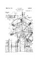
Figure 1 shows one arrangement of my system partly in elevation and partly in vertical section; V
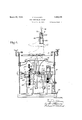
Fig. 2 is a top plan view of the system, port ions being omitted;
Fig. 3 illustrates in elevation a receiving tray supported upon the conveyor-chains;
Fig. 4 is a vertical section through the coating or operating section;
Fig. 5 is a vertical section through the conveying portion of the system;
Fig. 6 is a horizontal section on the line VI--VI of Fig. 1;.
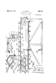
Fig. 7 illustrates the final conveying mechanism in elevation, looking from the left in Fig. 5
Fig- 8 is a detail'in broken side elevation of one of the work-grasping'devices and Fig. 9 is a perspective view showing the scraping means.
The system consists more essentially of such as is disclosed in Letters Patent of the United States No. 1,830,114, dated November 3,1931, and which performs an operation upon the work, as the cementing of portions of lasted shoes; transferring means B, which receives work from ti e presenting means; and conveying means C, in turn receiving work from the transferring means and delivering it for a succeeding operation. Both the transferring and conveying means may, while the work is under their influence, give intervals during which the cement or other fluid coating is allowed to dry. The manner in which the coating is applied at A forms no part of the present invention, and the coating means is illustrated diagrammatically only. It may be assumed that a lasted upper S, which is to receive a rubber sole, is resting upon spaced supporting bars 10, following the application to its bottom and foxing-area of a coating of cement indicated at s in Fig. 3. The cement may be projected against the work by a rotating cone N, the portions not to receive the coating being protected by a shield M. The bars 10 are a part of a frame or grid 12 (Figs. 1 and 4) carried at the upper extremity of a rod 14 guided in a cross member 16 of frame F. Pivotally connected to the rod is a link 18 joined at its other extremity to a crank 20 fixed at the in nor end of a shaft 22 journaled ho *izontally in thefraine. Fast upon the shaft 22 is a pinion 24 meshing with a gear 26 upon a shaft 28 journaled transversely of the section A. Rotation is imparted to the shaft 28 at a reduced speed from a main driving shaft 29 through worm-gearing 30, spurgearing 32 and a single-rotation clutch 34 controlled by a treadle at 36. Aturn of the crank 20 elevates the work-supporting grid from its lowermost or idle position to its highest work-presenting position, this requiring but a partial rotation of the shaft 25.. Since it is desired that the presenting operation shall occur but once for each rotation of the shaft 28, means is provided for governing the action of the latter upon the crank. There is also means for stopping the crank at its lowest point, at which it rests at the beginning of a cycle. The gear 26 is loose upon the shaft 28, and secured to the shaft, adjacent to the gear, is an arm 38, in the outer extremity of which a pin 40 is mounted to slide horizontally, a spring 42 holding said pin normally away from the gear. The inner face of the gear 26 hasan opening or abutment wall arranged for engagement by the pin 40. Situated in the path of the outer end of the pin is a cam 44 secured to the frame. The form and extent of this cam are such that, during a predetermined interval in the rotation of the gear, the pin is forced into contact with the opening, compelling the rotation of the crank 20,
and then, after said crank has moved through 360 degrees, being released by the cam. Sliding horizontally in a member fastened to the frame at the opposite side of the gear 26 from the pin 40, is a stop-pin 46 urged from the gear by a spring 48. The pin is caused to enter an opening in or to engage an abutmentwall on the gear by contact with its outer extremity of a cam 50 fast upon the shaft 28. It will be understood, therefore, that, with the support 12 in its lowered, inactive position, as shown in Fig. 4, in which the Work is being operated upon, this relation is maintained by the pin 46 under the influence of its cam 50, until the pin 40, in its revolution, reaches the cam 44. At this time, the pin 46 is disengaged from the gear by its spring, while the cam 44 thrusts the pin 40 into driving engagement with said gear. T he crank 20 is thereby turned through one revolution to raise and lower the support 12. Upon the return of the support to its normal lowered relation, the driving engagement between the pin and gear is released, as the former passes the cam 44, and the gear, and therefore the crank, is stopped in its rotation. by the movement of the pin 46 into retaining engagement with the gear by the cam 50.
Turning to the transferring section B, we have, rotatable about a vertical spindle rising from a frame-arm 54 (Fig. l), a carrierwheel 56, from which radiate arms 58, shown as seven in number though any other arrangement may be employed. So located upon each arm 58 that it will travel above and into vertical alinement with the workpresenting grid 12 as the wheel is rotated, is a work-receiving and grasping device Each device includes a pair of gposite jaws 60, 60 pivoted upon the arm 58 and furnished over their lower inner sides with yieldable facings 62, which may be of rubber to exercise an effective retaining action upon objects grasped. As herein illustrated, they are p ticularly designed to hold the cone of a l Joining the aws is a pair of toggle-1 its 64, 64, the central connecting pin 66 of which extends into, and is limited in its movement by, a vertical slot in a depending portion 66 of the arm. A spring T0, illustrated as of the scissors type,.draws the jaws normally toward each other. Depending from the togglepin 66 is a contact member 72 having a padded lower end normally extending between the jaws 60. Spaced pins 7 4, 74, projecting from the portion 68 of the arm, guide the member 7 2 in its vertical travel and also limit its upward movement by contact with them of at opposite sides of the member. Fixed to and extending upwardly from the pivot betwee the inner jaw 60 and the connected linlr 64, is an arm 76. The upper extremity of this arm revolves in a horizontal plane, in which lies a work-releasing plunger 7 8. This plunger. slides in arm 80 projecting fromithe spindle 52, andiis acted upon by a spring 82, which forces it normally towardthe path of the arms 76. Depending frointheiplungeris a projection 84 (Fig. 8) arrangedfor contact with a cam-surface 86- (Fig. 2))1extending about the inside of the wheel 56. The cam has upon it. a series ofinclinedfaces, eachof which terminates in a substantially radial pin 66 at this time passes somewhat by the I center, being limited in its downward movement by the bottom of the slot in the arm'- portion 68 in which it moves. The device G" V is thus made ready to receive the. succeeding piece of work, and, when a lasted shoe is elevated by the supporting grid 12, the cone of the last, striking against the member 72, forces the pin 66 upwardly by thecenter, and allows the spring 7 to close the grasping surfaces 62 of the jawszagainst the opposite sides of the work, thus holding it for transfer. v i
. The wheel 56 is rotated by. successive steps,
each step presenting one of the devices G above the grid 12 for the reception of a workpiece, while, at the same time, another device G is above a portion of the conveying section 7 C, having completed. a considerable portion of the'circuit about the periphery of the wheel and being solocated that itmay be-acted upon by the releasingplunger 78. The wheel has, at its periphery, gear-teeth 88,. with which meshes apinion (F ig.1 secured upon the upper end of a shaft 92 j ournaled vertically in the frame. Fixed to the shaft 92 is a pinion 94 engaging a gear 96 mounted to turn.
about a shaft 98 journaled in-theframe par- 4 5 allel to-the shaft 92. The rotation of the gear 96 with the, shaft 98 may be'compelled by a friction device including disks, 100 and 102 secured to the shaft, respectively below and above the gear. The disk 102 is splined for movement longitudinally of the shaft 98, and
is under the influence ofa helical spring 104 surrounding said shaft and tending to pro-- duce driving engagement between the gear and disks. Secured to the shaft .98, being shown as formed upon thedisk 100, is a pinion 106 engaging a gear 107 upon a vertical shaft 108, which is driven from'the shaft 28 of section A through worm-gearing, 110,
a shaft'112 and bevel-gearing 114. As itis i not, desirable to have the friction device engaged: andslipping when the wheel 56* is at rest during thereception and delivery of the work, the disk 102 may be raised from the gear 96' bya lever 11 6 fulcrumed upon the 2 frame, the free end of this lever being acted uponby a cam118 rotated by the shaft 108.
The contour of the cam-surface is, such that,
when the wheel is at rest, the disk102 is raised from the gear,-the frictional eifect thus ceasing; When the wheel is again .to be started in rotation to transfer the work, the cam-releases the disk 102, allowing the spring 104 to force it into driving engagement with the gear. I
To stop the wheel 56 in the correct position and there retain it during. the work-receiving and delivering operations, I have furnished stop mechanism. The under side of the wheel V has an opening or abutment-surface 120 (Fig. 2) corresponding to each of the arms 58. Into engagement with the opening at that time vertically alined with it may be raised a stoppin 122 (Fig. 1) guided in the frame-arm 54 and joined at 124 toa sleeve 126 sliding about the shaft 92. Opposite-links 128,128' connect the sleeve to a three-armed lever 130. (Fig. 6)
fulcrumed near the bottom of the shaft 92, I
one, of these arms contacting with a cam 132 fast upon the shaft 108. As the Wheel approaches the position at which it is to stop, and the cam 118 releases the friction device,
the cam 132 lifts the pin 122 into the opening in the wheel now alined with it, thus retain, mg. this positively against. movement.
Extending transversely of the transferring sectionB, beneath the spindle 52, is a horizontalframe carrying a series of pairs ofguide-rolls142', 142,.four of thesepairs being illustrated. The rolls have sides converging to their peripheries to enter two V- grooves formed in the under sides of elongated trays 1441, which may be of sheet-metal and constitute receivers for the work. The grooves are preferably pressed in the metal, producing parallel ridges 146 at the upper side of each tray, these ridges extending throughout the length. This length is suflicient to permit the desired number ofcemented shoe-uppers or other work-pieces to be deposited side by side upon the ridges, the tray width being such that it extends beneath the ends of the pieces. It will be seen that,
in additionto producing ways operating over the rolls 142, the ridges 146 elevate the shoebottoms above anyadhesive which'may ac cumulate upon a tray, and. also, by their narrow lines of contact, minimize disturbance of the coated surfaces. Y
J ournaled near opposite extremities of the frame 140 are shafts 148and 150" (Fig. 5) carrying sprocket wheels 152,152 belonging to the conveying section C. Over these sprocket-wheels operates a chain 154, from which are two projections 1556, 156, extending, when at the upper sideof the frame,
accomplished through a sprocket-wheel 160 upon the shaft 148 joined by a chain 162 to a sprocket-wheel 16 1 upon a horizontal shaft 166. This shaft is rotated through bevelgearing 168 (Fig. 1) from the shaft 108.
To insure the proper timing of 'the chain 154 in its advance, the sprocket-wheel 16-1 is normally free to turn about the shaft 166,
and adjacent to itis a disk 170 (Fig. 1) keyed to the shaft. Movable horizontally in the disk is a pin 172, held yieldably away from the wheel 164: by a spring 174. (lo-operat ing with the outer extremity of the pin is a stationarycam 17 During the deposit of a work-piece upon the tray from one of the grasping devices G, the pin 172 is Withdrawn from contact with the sprocket-wheel 16% by its spring, the earn 176 permitting this. But after the work is in place upon the tray, the pin is moved by the cam into driving engagement with the wheel, and thus retained for a suflicient length of time to advance the tray quickly a single step in the direction ofits length, locating it to receive the next piece of work clear of but in close proximity to that preceding it.
As the forward end of a tray 14% is carried beyond the supporting frame 140, it is received upon guide-rolls 180, which enter its grooves, as did the rolls 142. These rolls 180 are shown as mounted in pairs upon bars 182 secured to chains 18 1 operating over sprocket- wheels 186, 186 7) fixed upon shafts 188, 188 turning in the frame. Geared at 190 to one of the shafts 188 is a shaft 192, to which is fixed a ratchet-wheel 19 1. With the teeth of the ratchet-wheel co-operates a pawl 196 carried by a lever 198 fulcrumed upon the shaft 192. To the free end of the lever a treadle 200 is connected. After a tray Met has been filled and'delivered upon the rolls of the'conveyer-chains 18 1, the operator or operators assistant may apply an empty tray to the rolls 142, and, by means of the treadle 2'00, bring another set of rolls 180 into their tray-receiving alinenient, the
filled tray being advanced a step by the chains 184:. i The full trays continue to accumulat-e upon and be forwarded by the chains 18 1 until the end farthest from the receiving portion is reached, when they are removed withtheir contents for the utilization of the latter. In the meantime, during 7 their transfer upon the wheel,the collecting movement of the trays under the influence of the chain 154 and their final travel upon the chains184, the cementor other coating is being dried untilit is in the proper condition for the performance of the next making operation.
Coated work may carry such an amount of the applied liquid that it will drip during its transfer between the coating and conveying sections. To receive this, there is situated beneath the path of the grasping devices G a segmental pan 202 (Fig. 2), supported upon the frame and extending from as, just forward of the receiving position, into proximity with the delivering position at y. Means may also be associated with the lastmentioned end of the pan for removing from the work any excess of the adhesive still carried by it. Referring particularly to Fig. 9 of the drawings, there is placed be low the end of the pan, at 3 a receptacle 1. At the rear edge of the receptacle are pivoted a plurality of scrapers, three being herein disclosed and designated by the numerals 206, 208 and 210. Each scraper is forced normally upward into the path of the shoe-bottoms in the grasping devices by a spring 212. The scraping edges preferably are differently formed, that of 206 lying in a straight, horizontal line, the edge of 208 having sides converging to the center at an angle somewhat less than 180 degrees, and the edge of 210 having sides similarly related to 208 but being at a less angle to each other. By the action of theseplural mem hers, substantially the entire bottom of each shoe may be freed from the excess of the coating. Screws 214, threaded through depending arms upon the scrapers and contacting with the support for the receptacle, permit the normal positions of said scrapers to be varied. Since the relation of the shoes to the vertical, being always bottom-down, remains unchanged from the time of coating to final delivery, there will be no tendency for the cement to flow upon the upper-area to be left uncoated.
The co-operative action of the three sections of the system is as follows: Assuming that a lasted shoe-upper S, to which a rubber sole is to be applied and which has been cemented over the bottom and foXing-area s at section A by the delivery from the cone N, is upon the lowered support 12, and that a grasping device G of the transferring section B is at rest in the position illustrated at a in Fig. 2 of the drawings, the operator depresses the treadle 36, thus initiating the cycle of the various automatic mechanisms. 1
Rotation of the cam 118 engages the frictiondisks and 102 with the gear 96 and starts the wheel 56 rotating'in the direction of the arrow (Fig. 2), this continuing until the jaws of the grasping device G are vertically alined at b with the cone of the last upon the support 12. Thenthe friction is released and the cam 132 produces the elevation of the stop-pin 122 to retain'the wheel in the desired position. At this time, the pin 40 has reached a point at which it is moved by the cam 44 into driving engagement with the gear 26, elevating the support 12 to thrust the cone of the last'between the jaws of the grasping device, where it is retained by the rubber pads 62, the togglelever 64, 64 having been forced by the center to permitthis engagement by contact of the last-cone with the member 72. Simultaneously, the cam 176 has acted upon the pin 172to cause the driving of the sprocket-wheel 164 by the disk 170. Thus, while the work is being delivered from the cementing support to the grasping device at b, a piece previously received upon a tray 144, resting upon the rolls 142 and located at d, is carried forward by movement of the tray, so that a free space is left thereon for the re- "ception of the succeeding piece of work. The
Having described my invention, what 1 I claim as new and desire to secureby Letters Patent of the United States is:
1. In a work-forwardingsystem, an apparatus for performing operations upon succes sive pieces of work in a predetermined position with respect to the vertical, a receiver for the work operated upon, said receiverbeing constructed and arranged for removal with its contents to another operating position, means for transferring work piece by piece from the apparatus to the receiver, while maintaining the position in which the operation was performed, and means for moving the receiver step by step in continued co-operation with the transferring means for the reception of a series of work-pieces by it.
2. In a work-forwardin system, an apparatus for performing operations upon successive pieces of work, receivers for the work operated upon, each of said receivers being constructed and arranged for removal with its contents to another operating position, means for transferringwork piece by piece to a receiver, means for moving said receiver step by step for the reception of a series of work-pieces by it, and means advancing successive receivers from their cooperation with the transferring means.
3. In a Work-forwarding system, an appa ratus for performing operations upon successive pieces of work,anelongated receiver for the work operated upon, means 'movable about a vertical axis for transferring work piece by piece from theapparatus to the receiver, and a conveyor arranged to move the receiver step by step in the direction of its length for the reception of the work-pieces by it.,
4. In a work-forwarding system, anapparatus for performing operations upon slicessive pieces of work, an elongated receiver for the work operated upon, means for transferring work piece by piece to the receiver, a conveyor arranged to'move the receiver step by step in the direction of its length for the reception of the work-pieces by it, a conveyor to which thefilled receiver is advanced longitudinally, and means for advancing the receiving, conveyor in steps corresponding to the width of the receivers.
5. In a system for forwarding coated shoes, transferring apparatus to which coat ed shoes are delivered in a predetermined relation to the coated area, and a tray upon which the shoes are successively deposited by the transferring apparatus. Y
6. In a system for forwarding lasted shoeuppers from a'coating apparatus, transfer-1 ring means having opposite engagingmembers, and means for thrusting the cone of a last carrying a coated upper between the engaging members.
7 In a system for. forwarding coated shoes, transferring apparatus towhich ,coat
ed shoes are delivered, and a tray upon which the shoes are successively deposited by the transferring apparatus, said tray having upon its upper face ridges to support the shoes.
8. In a system for forwarding shoes coated over certain areas, transferring apparatus having a device arranged to grasp the work outside the coated area, and a tray upon which the grasping device deposits the work.
9. In a system for forwarding coated shoes, transferring apparatus to which coated shoes are delivered in a predetermined relation to the coated area, a tray upon which the shoes are successively deposited by the transferring apparatus, and means for moving the tray step by step beneath the transferring apparatus to an extent sufficient to space successive shoes from each other on said tray.
10. In a system for forwarding coated shoes, transferring apparatus to which coated shoes are delivered, a tray upon which the shoes are successively deposited by the transferring apparatus, said tray having upon its upper face ridges to support the shoes, grooves at the under sides of the ridges, guides engaging the grooves, and means for moving the tray step by step over the guides.
11. In a system for forwarding coated shoes, transferring apparatus to which coated shoes are delivered, a tray upon which the shoes are successively deposited by the transferring apparatus, means for moving the tray step by step in constant receiving association with the transferring apparatus, advancing means upon which the filled trays are delivered and means for operating the advancing means in steps corresponding to a dimension of the trays.
12. In a system for forwarding shoes coated over certain areas, transferring apparatus having a device arranged to grasp the work outside the coated area, a tray upon which the grasping device deposits the work, and a conveyor provided with a projection engaging the tray.
13. In a system for forwarding shoes coated over certain areas, transferring apparatus having a device arrangedto grasp the work outside the coated area, a tray upon which the grasping device deposits the work, a conveyor provided with a projection engaging the tray, and means for operating the conveyor in steps corresponding to the successive deposits of the coated shoes upon the tray.
14. In a system for forwarding shoes coated over certain areas, transferring apparatus having a device arranged to grasp the work outside the coated area, a tray upon which the grasping device deposits the work, a conveyor provided with a projection engaging the tray, means for operating the conveyor in steps corresponding to the successive deposits of the coated shoes upon the tray, and a conveyor to which the trays are delivered by the step-by-step operation of the first mentioned conveyor.
15. In a system for forwarding coated shoes, transferring apparatus to which coated shoes are delivered, a tray upon which the shoes are successively deposited by the trans ferring apparatus, and scraping means acting upon the work during its transfer.
16. In a system for forwarding coated shoes, transferring apparatus having a device arranged to grasp the work outside the coated area, a scraper with which the work contacts while thus grasped, and a tray upon which the grasping device deposits the work.
17 In a system for forwarding coated shoes, transferring apparatus to which coated shoes are delivered, a tray upon which the shoes are successively deposited bottomsdown by the transferring apparatus, and a plurality of scrapers contacting with the shoebottoms during their transfer and having their contact-edges lying at different angles.
18. In a system for forwarding coated shoes, transferring apparatus to which coated shoes are delivered, a tray upon which the shoes are successively deposited bottoi'ns-down by the transferring apparatus, and a plurality of scrapers having operating edges formed differently from one another and successively contacting with the shoe-bottoms during their transfer.
19. In a work-forwarding system, a cement-applying apparatus including a support for work during the application of cement thereto, said support being movable, and transferring means arranged to receive the cemented work in the movement of the support.
20. In a work-forwarding system, a cement-applying apparatus including a sup port for work during the application of cement thereto, said support being movable, and transferring means having opposite jaws arranged to be separated by the work moved by the cementing support and to retain such cemented work.
21. In a work-forwarding system, transferring means having a plurality of grasping devices, means for effecting the engagement of the work by each grasping device, a member movable to release plural devices, and means controlled by the transferring means for moving the member.
22. In a work-forwarding system, transferring means having a traveling grasping device, means for thrusting the work into engagement with the grasping device, and movable impact means energized in the travel of the grasping device for contact therewith to release its grasp upon the work.
23. In a work-forwarding system, a support on which an operation is performed upon the work, transferring means provided with opposite'jaws movable in proximity to the support, means for holding the jaws normally separated, a contact member located between the jaws and arranged to control said jaws, and means for elevating thesupport to carry the work between the aws and against the contact member.
24. In a shoe-forwarding system for use in connection with cementing apparatus, a support arranged to hold a lasted shoe bottom-down, transferring means provided with a grasping device, and means for moving the support and transferring means relatively to cause retaining engagement between the grasping device and the cone of the last carrying a cemented upper upon said support.
25. In a shoe-forwarding system for use in connection with cementing apparatus, a
support arranged to hold a lasted shoe bottom-down during the cementing operation, transferring means provided with jaws having opposite yieldable faces, and means for moving the support to thrust the cone of the last thereon into co-operation with the yieldable faces of the jaws.
26. In a system for forwarding coated shoes a support arranged to hold a coated, lasted shoe bottom-down, transferring meansprovided with jaws having opposite yieldable faces, means for moving the support to thrust the cone of the last thereon into co-operation with the yieldable faces of the jaws, and a scraper with which the shoe contacts while in the grasp of the jaws.
27. In a work-forwarding system, transferring means, guide members arranged below the transferring means, a receiver sup ported upon the guide members, means for moving the receiver over the guide members, and a conveyor having guide members movable into alinement with those below the transferring means.
28. In a work-forwarding system, transferring means, series of rolls arranged be low the transferring means, a tray resting upon the rolls, a conveyor engaging the tray, and a conveyor provided with series of rolls movable successively into alinement with the first-mentioned series of rolls.
29. In a work-forwarding system, traveling pairs of jaws, means for moving the jaws to grasp the work, a member arranged for successive action on the pairs of aws to separate them from the work, and means movable with the aws in their travel for controlling the movement of the member.
30. In a work-forwarding system, a travcling pair of jaws arranged to grasp the work, a movable contact member for releasing the work from the grasp of the jaws, a sprin arranged to produce the releasing action of the member, and means traveling with the jaws for energizing the spring.
31. In a work-forwarding system, a traveling pair of jaws arranged to grasp the work,
ing pair of jaws arranged to grasp the work,
a spring arranged to force the jaws toward each other, a toggle-lever connecting the jaws, a member carried by the toggle-lever and arranged for contact with the work, an arm extending from the toggle-lever, and means acting upon the arm to separate the aws.
means for operating upon the supported work,
during the withdrawal of the support from the wheel, means for intermittently stopping the wheel to successively aline the pairs of jaws with the support, and means for reciprocating the support to thrust the work between the jaws.
35. In a work-forwarding system, the combination with a rotatable wheel, of a series of pairs of aws carried by the wheel, a worksupport movable toward and from the wheel,
means for intermittently stopping the wheel to successively aline the pairs of jaws with the support, means for reciprocating the support to thrust the work between the jaws, and means including an element mounted upon the wheel and acting simultaneously with such delivery to a pair of jaws for releasing the work from another pair.
36. In a work-forwarding system, the combination with a rotatable wheel, of a series of pairs of aws carried by the wheel, a worksupport movable toward and from the wheel, means for intermittently stopping the wheel to successively aline the pairs of jaws with the support, means for reciprocating the support to thrust the work between the jaws, means acting simultaneously with such delivery to a pair of jaws for releasing the work from another pair, a tray upon which the released work is deposited, a conveyor engaging the tray, and means acting upon the cenveyor to feed the tray step by step to receive successive work-pieces from the wheel.
37. In a work-forwarding system, the combination with a rotatable wheel, of aseries of pairs of jaws carried by the wheel, a work-support movable toward and from the wheel, means for intermittently stopping the wheel to successively aline the pairs of jaws with the support, means for reciprocating the support to thrust the work between the jaws, means acting simultaneously with such deli my to a pair of jaws for releasing the work from another pair, a tray upon which the released work is deposited, a conveyor engaging the tray, means acting upon the conveyor to feed the tray step by step to receive successive work-pieces from the wheel, and a conveyor to which the tray is delivered at the termination of its workreceiving movement.
In testimony whereof I have signed my name to this specification.
FAY D. KINNEY.
Priority Applications (1)
| Application Number | Priority Date | Filing Date | Title |
|---|---|---|---|
| US324029A US1850151A (en) | 1928-12-05 | 1928-12-05 | Work-forwarding system |
Applications Claiming Priority (1)
| Application Number | Priority Date | Filing Date | Title |
|---|---|---|---|
| US324029A US1850151A (en) | 1928-12-05 | 1928-12-05 | Work-forwarding system |
Publications (1)
| Publication Number | Publication Date |
|---|---|
| US1850151A true US1850151A (en) | 1932-03-22 |
Family
ID=23261762
Family Applications (1)
| Application Number | Title | Priority Date | Filing Date |
|---|---|---|---|
| US324029A Expired - Lifetime US1850151A (en) | 1928-12-05 | 1928-12-05 | Work-forwarding system |
Country Status (1)
| Country | Link |
|---|---|
| US (1) | US1850151A (en) |
Cited By (10)
| Publication number | Priority date | Publication date | Assignee | Title |
|---|---|---|---|---|
| US2443877A (en) * | 1946-09-23 | 1948-06-22 | Joyce Inc | Apparatus for manufacturing footwear utilizing sub-assemblies and applying the same directly to the lasts |
| US2623650A (en) * | 1947-08-09 | 1952-12-30 | Philip S Allen | Film transporting mechanism for automatic photographic apparatus |
| US2740140A (en) * | 1952-03-14 | 1956-04-03 | United Shoe Machinery Corp | Machines for shaping the toe portions of slip-lasted shoes |
| DE1122412B (en) * | 1960-04-29 | 1962-01-18 | United Shoe Machinery Corp | Automatic device for loading an automatic shoe machine |
| US3018007A (en) * | 1958-05-05 | 1962-01-23 | Westinghouse Electric Corp | Transfer apparatus |
| US3128881A (en) * | 1964-04-14 | Kghnle | ||
| US3137330A (en) * | 1962-12-03 | 1964-06-16 | Pioneers Proc Equipment | Egg handling machinery |
| US3274749A (en) * | 1963-05-29 | 1966-09-27 | Western Electric Co | Article unloading and transfer apparatus |
| US3751744A (en) * | 1971-04-09 | 1973-08-14 | Z Presneko Strojirenstvi Gottw | Arrangement for tensioning the shank part of a shoe-upper |
| US4876434A (en) * | 1984-09-04 | 1989-10-24 | British United Shoe Machinery Limited | Curing coatings of a moisture-curable composition |
-
1928
- 1928-12-05 US US324029A patent/US1850151A/en not_active Expired - Lifetime
Cited By (10)
| Publication number | Priority date | Publication date | Assignee | Title |
|---|---|---|---|---|
| US3128881A (en) * | 1964-04-14 | Kghnle | ||
| US2443877A (en) * | 1946-09-23 | 1948-06-22 | Joyce Inc | Apparatus for manufacturing footwear utilizing sub-assemblies and applying the same directly to the lasts |
| US2623650A (en) * | 1947-08-09 | 1952-12-30 | Philip S Allen | Film transporting mechanism for automatic photographic apparatus |
| US2740140A (en) * | 1952-03-14 | 1956-04-03 | United Shoe Machinery Corp | Machines for shaping the toe portions of slip-lasted shoes |
| US3018007A (en) * | 1958-05-05 | 1962-01-23 | Westinghouse Electric Corp | Transfer apparatus |
| DE1122412B (en) * | 1960-04-29 | 1962-01-18 | United Shoe Machinery Corp | Automatic device for loading an automatic shoe machine |
| US3137330A (en) * | 1962-12-03 | 1964-06-16 | Pioneers Proc Equipment | Egg handling machinery |
| US3274749A (en) * | 1963-05-29 | 1966-09-27 | Western Electric Co | Article unloading and transfer apparatus |
| US3751744A (en) * | 1971-04-09 | 1973-08-14 | Z Presneko Strojirenstvi Gottw | Arrangement for tensioning the shank part of a shoe-upper |
| US4876434A (en) * | 1984-09-04 | 1989-10-24 | British United Shoe Machinery Limited | Curing coatings of a moisture-curable composition |
Similar Documents
| Publication | Publication Date | Title |
|---|---|---|
| US1850151A (en) | Work-forwarding system | |
| US4639963A (en) | Shoe manufacturing system | |
| US2222605A (en) | Apparatus for assembling antifriction bearings | |
| US1846324A (en) | Stacking apparatus | |
| US1978004A (en) | Transferring system | |
| US2957290A (en) | Olive packing machine | |
| US3147500A (en) | Processing of shoe soles | |
| US2279994A (en) | Apparatus for applying material to parts | |
| US1575037A (en) | Bail-placing machine | |
| US2355249A (en) | Automatic metal treating machine | |
| US2785682A (en) | Apparatus for cigar machines | |
| US2409631A (en) | Can making machine | |
| US2333708A (en) | Assembling machine | |
| US3359585A (en) | Method and apparatus for attaching shoe soles | |
| US1251852A (en) | Feed mechanism. | |
| US1673826A (en) | Coating apparatus | |
| US1808810A (en) | Positioning apparatus | |
| US1780195A (en) | Sheet-separating apparatus | |
| US1593882A (en) | Conveyer for driers | |
| US2106171A (en) | Flexing machine | |
| US1166071A (en) | Dipping-machine. | |
| US2406456A (en) | Fishhook making machine | |
| US2885058A (en) | Shoe handling apparatus | |
| US1352745A (en) | Means for feeding articles in stacked relation | |
| US3102285A (en) | Insole molding machines |