US1851148A - Leveling mechanism - Google Patents
Leveling mechanism Download PDFInfo
- Publication number
- US1851148A US1851148A US427903A US42790330A US1851148A US 1851148 A US1851148 A US 1851148A US 427903 A US427903 A US 427903A US 42790330 A US42790330 A US 42790330A US 1851148 A US1851148 A US 1851148A
- Authority
- US
- United States
- Prior art keywords
- shafts
- carriage
- shaft
- nut
- casing
- Prior art date
- Legal status (The legal status is an assumption and is not a legal conclusion. Google has not performed a legal analysis and makes no representation as to the accuracy of the status listed.)
- Expired - Lifetime
Links
Images


Classifications
-
- F—MECHANICAL ENGINEERING; LIGHTING; HEATING; WEAPONS; BLASTING
- F41—WEAPONS
- F41A—FUNCTIONAL FEATURES OR DETAILS COMMON TO BOTH SMALLARMS AND ORDNANCE, e.g. CANNONS; MOUNTINGS FOR SMALLARMS OR ORDNANCE
- F41A23/00—Gun mountings, e.g. on vehicles; Disposition of guns on vehicles
- F41A23/56—Arrangements for adjusting the gun platform in the vertical or horizontal position
Definitions
- This invention relates to leveling mechanism, especially applicable for gun carriages.
- the gun mount In order that the fire control data for laying a gun in azimuth and elevation may be accurately applied,-the gun mount must be level. Leveling mechanisms for accomplishing this purpose have been associated with field and fixed mounts but always in such a manner that the controls are positioned in the immediate vicinity of the mount. According to the present invention, it is proposed to actuate the leveling mechanisms from a remote station such as the drivers seat of a self-propelled vehicle so that the gun mount which is at the rear of the vehicle may be maintained in constant adjustment even when the vehicle is in motion.
- a remote station such as the drivers seat of a self-propelled vehicle
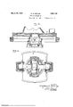
- Fig. 1 is a view partly in side elevation and partly in section of a vehicle carrying a gun mount and equipped with the improved leveling mechanism;
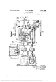
- Fig. 21's 21 plan view more or less diagrammatic of the leveling mechanism
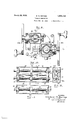
- Figs. 3 and 4 are respectively vertical and horizontal sectional view through the suspensionof the gun mount;
- Fig. 5 is a detail sectional view on the line 55 of Fig. 1;
- Fig. 6 is a detail sectional view on the line 66 of Fig. 5;
- Fig. 7 is a vertical sectional view of the control mechanism, taken on the line 7-7 of Fig. 8;
- Fig. 8 is a plan View, parts being in section, of the control mechanism
- Fig. 9 is a sectional view on the line 99 of Fig. 8;
- Fig. 10 is a plan. view of the mechanism Y for limiting rotation of the main drive shafts Fig. 11 is a view in side elevation thereof;
- Fig. 12 is a sectional view on the line 1212 of Fig. 10;
- Fig. 13 is a sectional View on line 1313 of Fig. 7.
- a self propelled spring mounted vehicle 4 having the usual chassis 5 on which is secured a pedestal 6.
- a gun mount 7 is place on a base plate 8 which overlies the pedestal and has a depending portion 9 inserted therein.
- the portion 9 (Figs. 3 and 4) is supported on the pedestal by means of crossed shafts, the main shaft 10 trunnioned in the pedestal and a shorter shaft 11 fixed in the main shaft and trunnioned in the depending portion 9.
- a spindle 12 Secured to the portion 9 is a spindle 12 having a ball and socket connection 13 (Figs. 5 and 6) with a carriage 14 which is movable on a second carriage 15 mounted to slide on rails 16 on the fioor of the pedestal.
- the carriages are movable at right angles to each other and in the preferred embodiment the upper carriage 14 is arranged for movement longitudinally of the vehicle (Fig. 2) while the lower carriage 15 is movable transversely thereof.
- a shaft 17 fixed to the lower carriage 15 eX- tends laterally and is in engagement (Fig. 5) with an internally threaded sleeve 18 supported in bearings 19 in a bracket 20 of the pedestal 6 and driven through gearing 21 from a shaft 22.
- a shaft, 23 fixed to the upper carriage 14 terminates within an internally threaded sleeve 24 supported in bearings 25 in an extension 26 of the lower carriage 15.
- the sleeve 24 is connected by means of a universal coupling 27 to a short shaft 28 splined in a tubular driving shaft. 29.
- the shafts 22 and 29 lead towards the cab 30 of the vehicle, passing through a casing 31 containing reduction gearing and then through a casing 32 in which is placed mechanism for limiting rotation of the shafts.
- This mechanism (Figs. 10 to 12) consists of dogs 33-33 one threaded on each of the shafts and partially surround an intermediately positioned rod 34 whereby it is held against rotation and constrained to longitudinal displacement; Inorder to prevent binding and injury to the threads when the dogs 33 reach the limit of their movement and are arrested by the end plates 35, both the dogs and plates are'formed with complementary claws 33 and 35
- the control mechanism for the shafts 22 and 29 is contained in a casing 36 secured to the floor of the cab in a position for convenient access to an operator occupying a seat 37.
- This mechanism comprises a pair of hand wheels 22 and 29 (Figs. 7 and 8) extending out of line with each other through opposite sides of the casing and respectively connected through similar gearing 38 to vertical shafts 22 and 29.
- a vertical rod 40 Mounted in the casing 36 through a ball and socket connection 39 is a vertical rod 40 having at its upper extremity a circular spirit level 41. The axis of this rod is parallel to the vertical axis of the spindle 12 of the gun mount.
- the lower extremity of the rod 40 has a ball and socket connection 42 with a leveling mechanism actuated from the shafts 22 and 29 through gearing 22 and 29 and a pair of crossed screw shafts 22 and 29 journaled in the casing 36.
- the shaft 22 is uppermost and carries a squared traveling nut 43 which is positioned in and engages the upper and lower walls of an elongated, rectangular opening or slot 44 in a carriage 45.
- the carriage is confined between flanges on the end of the nut 43 so that it is obliged to travel with the nut while being free to move in a path at right angles to the path of movement of the nut.
- the screw shaft 29 which is lowermost likewise carries a traveling nut 46 held against rotation by a sliding engagement 47 with an anchor plate 48.
- the nut 46 is also in engagement with the lower part of the carriage 45 through a tongue and groove connection 49 extending transversely of the shaft 29 riage 45, while movable parallel to the screw shaft 29 is also mounted for movement parallel to the screw shaft 22 and since the upper portion of the carriage is provided with the socket element of the connection 42, the vertical rod 40 carrying the spirit level may be tilted in planes at right angles to each other.
- the operator occupying a seat in the cab of the vehicle controls both of the hand wheels 22 and 29 and manipulates them in a manner to maintain the spirit level in adjust- By virtue of this arrangement the car-' ment with its bubble on the cross-hairs 50.
- the upper shaft 22 acting through the nut 43 and the lower shaft 29 acting through the nut 46 move the carriage in directions at right angles to each other.
- Corresponding movements are communicated to the gun mount through the shafts 22 and 29 to similarly move the respective carriage 15 and 14 and maintain the spindle 12 of the gun mount parallel to the rod 40 carrying the spirit level 41.
- the shaft 28 splined to the shaft 29 and extensible with respect thereto provides for the bodily displacement of the upper frame 14 transversely of the vehicle.
- the preservation of the level of a gun mount is of particular importance where fire control data is to be accurately applied in laying a gun or guns to the proper azimuth and elevation.
- a leveling mechanism a pedestal, a gun mount supported thereon for universal movement, members movable at right angles to each other and connected through one of them to the gun mount, a control mechanism remote from the pedestal, a drive shaft connecting the control mechanism with each of said movable members, the shaft leading to that member connected to the gun mount being extensible, means for limiting rotation of the drive shafts, and a level indicator associated with the control mechanism.
- a leveling mechanism a pedestal, a gun mount supported thereon for universal movement, members movable at right angles to each other and connected through one of them to the gun mount, a control mechanism remote from the pedestal, a drive shaft connecting the control mechanism with each of 7 said movable members, one of said shafts being extensible, and a level indicator associated with the control mechanism.
- a pedestal secured on the rear thereof, a gun mount supported on the pedestal for universal movement, means whereby the gun mount is movable in planes at right angles to each other, a con-' trol mechanism in the front of the vehicle for actuating said means and a level indicator associated with the control mechanism.
- a gun mount universally supported thereon, and means for leveling the gun mount extending from a remote part of the vehicle, one of said means being extensible.
- a leveling device including a support, a main shaft trunnioned in the support, a cross shaft fixed to the main shaft, a member rotatably supported on the cross shaft and means for moving said member in the planes of said shafts.
- a leveling device a casing, drive shafts extending out of line through opposite sides of the casing, a driven shaft geared to each of the drive shafts, a screw shaft geared to each of the driven shaftsand journaled in the casing one above the other, said screw shafts crossing each other at right angles, a traveling nut on each of said screw shafts, an anchor having sliding engagement with the lower nut, a carriage having a tongue and groove connection with and transversely of the lower nut, said carriage provided with a slot receiving the upper nut and disposed transversely thereof, means on the ends of the upper nut for confining two opposite sides of the carriage, and a universally supported level indicator engageable with the carriage.
- a leveling device a casing, a pair of crossed screw shafts journaled in the casing, one above the other, a traveling nut on each of said screw shafts, an anchor having sliding engagement with the lower nut, a carriage having a tongue and groove connection with and transversely of the lower nut, said carriage provided with a slot receiving the upper nut and disposed transversely thereof, means on the ends of the upper nut for confinin two opposite sides of the carriage, and a universally supported level indicator engageable with the carriage.
- a casing a pair of crossed screw shafts journaled in the casing one above the other, a traveling nut on each of said shafts, a carriage having a sliding engagement with and transversely of each of the nuts, and means on each nut engageable with the carriage whereby the carriage is movable with each nut.
- a control mechanism a casing, a pair of crossed screw shafts journaled in the casing one above the other, a traveling nut on each of the said shafts, a carriage having a sliding and a non-sliding engagement with each of the nuts.
- a pair of spaced screw shafts mounted to cross at right angles, a rectilinearly movable member on each of said shafts and a member engaged for movement with each of the rectilinearly movable members and mounted for movement transversely of each of them.
- a pair of spaced screw shafts mounted to cross each other, a rectilinearly movable member on each of said shafts and a member engaged for movement with each of the rectilinearly movable members and mounted for movement transversely of each of them.
Description
March 29,1932. 3. M. BARNES 1,851,148
LEVELING MECHANISM Filed Feb. 12, 1930 5 Sheets-Sheet 1 IN V EN TOR;
Gladecm M-Ear'TLE5 March 29, G M, BARNES LEVELING MECHANISM Filed Feb. 12, 1950 5 Sheets-Sheet 2 INVENTOR. Eladaun I LEarnes BY 77 A TORNEYSI.
March-29, 1932. G. M. BARNES LEVELING MECHANISM File d Feb. 12, 1930 5 Sheets-Sheet 3 INVENTOR. Elaclecm M-E1ar'nEs BY WW @M TTORNEYS.
a. lllflllll March 29, 1932. s. M. BARNES 1,851,148
LEVELING MECHANISM File d Feb. 12, 19:50 '5 Sheets-Sheet 4 Bladecm M.Earnes March 29, 1932. G. M. BARNES 1,851,148
LEVELING MECHANI SM Filed Feb. 12, 1930 5 Sheets-Sheet 5 IN V EN TOR.
11 Eladeun M-Earne5 T ORNEYS.
Patented Mar. 29, 1932 GLADEON M. BARNES, F HASTINGS, MICHIGAN LEVELING MECHANISM Application filed February 12, 1930. Serial No. 427,903.
(GRANTED UNDER THE ACT OF MARCH 3, 1883, AS AMENDED APRIL 30, 1928; 370 0. G. 757) The invention described herein may be manufactured and used by or for the Govern ment for governmental purposes, without the payment to me of any royalty thereon.
This invention relates to leveling mechanism, especially applicable for gun carriages.
In order that the fire control data for laying a gun in azimuth and elevation may be accurately applied,-the gun mount must be level. Leveling mechanisms for accomplishing this purpose have been associated with field and fixed mounts but always in such a manner that the controls are positioned in the immediate vicinity of the mount. According to the present invention, it is proposed to actuate the leveling mechanisms from a remote station such as the drivers seat of a self-propelled vehicle so that the gun mount which is at the rear of the vehicle may be maintained in constant adjustment even when the vehicle is in motion.
With the foregoing and other objects in view, the invention resides in the novel arrangement and combination of parts and in the details of construction hereinafter described and claimed, it being understood that changes in the precise embodiment of the invention herein disclosed may be made within the scope of what is claimed without departing from the spirit of the invention.
A practical embodiment of the invention is illustrated in the accompanying drawings, wherein:
Fig. 1 is a view partly in side elevation and partly in section of a vehicle carrying a gun mount and equipped with the improved leveling mechanism;
Fig. 21's 21 plan view more or less diagrammatic of the leveling mechanism;
Figs. 3 and 4 are respectively vertical and horizontal sectional view through the suspensionof the gun mount;
Fig. 5 is a detail sectional view on the line 55 of Fig. 1;
Fig. 6 is a detail sectional view on the line 66 of Fig. 5;
Fig. 7 is a vertical sectional view of the control mechanism, taken on the line 7-7 of Fig. 8;
Fig. 8 is a plan View, parts being in section, of the control mechanism;
Fig. 9 is a sectional view on the line 99 of Fig. 8;
Fig. 10 is a plan. view of the mechanism Y for limiting rotation of the main drive shafts Fig. 11 is a view in side elevation thereof;
Fig. 12 is a sectional view on the line 1212 of Fig. 10; and
Fig. 13 is a sectional View on line 1313 of Fig. 7.
Referring to the drawings by characters of reference:
In Fig. 1 there is shown a self propelled spring mounted vehicle 4 having the usual chassis 5 on which is secured a pedestal 6. A gun mount 7 is place on a base plate 8 which overlies the pedestal and has a depending portion 9 inserted therein. The portion 9 (Figs. 3 and 4) is supported on the pedestal by means of crossed shafts, the main shaft 10 trunnioned in the pedestal and a shorter shaft 11 fixed in the main shaft and trunnioned in the depending portion 9.
Secured to the portion 9 is a spindle 12 having a ball and socket connection 13 (Figs. 5 and 6) with a carriage 14 which is movable on a second carriage 15 mounted to slide on rails 16 on the fioor of the pedestal. The carriages are movable at right angles to each other and in the preferred embodiment the upper carriage 14 is arranged for movement longitudinally of the vehicle (Fig. 2) while the lower carriage 15 is movable transversely thereof.
A shaft 17 fixed to the lower carriage 15 eX- tends laterally and is in engagement (Fig. 5) with an internally threaded sleeve 18 supported in bearings 19 in a bracket 20 of the pedestal 6 and driven through gearing 21 from a shaft 22.
A shaft, 23 fixed to the upper carriage 14 terminates within an internally threaded sleeve 24 supported in bearings 25 in an extension 26 of the lower carriage 15. The sleeve 24 is connected by means of a universal coupling 27 to a short shaft 28 splined in a tubular driving shaft. 29.
The shafts 22 and 29 lead towards the cab 30 of the vehicle, passing through a casing 31 containing reduction gearing and then through a casing 32 in which is placed mechanism for limiting rotation of the shafts. This mechanism (Figs. 10 to 12) consists of dogs 33-33 one threaded on each of the shafts and partially surround an intermediately positioned rod 34 whereby it is held against rotation and constrained to longitudinal displacement; Inorder to prevent binding and injury to the threads when the dogs 33 reach the limit of their movement and are arrested by the end plates 35, both the dogs and plates are'formed with complementary claws 33 and 35 The control mechanism for the shafts 22 and 29 is contained in a casing 36 secured to the floor of the cab in a position for convenient access to an operator occupying a seat 37. This mechanism comprises a pair of hand wheels 22 and 29 (Figs. 7 and 8) extending out of line with each other through opposite sides of the casing and respectively connected through similar gearing 38 to vertical shafts 22 and 29.
Mounted in the casing 36 through a ball and socket connection 39 is a vertical rod 40 having at its upper extremity a circular spirit level 41. The axis of this rod is parallel to the vertical axis of the spindle 12 of the gun mount. The lower extremity of the rod 40 has a ball and socket connection 42 with a leveling mechanism actuated from the shafts 22 and 29 through gearing 22 and 29 and a pair of crossed screw shafts 22 and 29 journaled in the casing 36.
As shown in Figs. 7 and 9, the shaft 22 is uppermost and carries a squared traveling nut 43 which is positioned in and engages the upper and lower walls of an elongated, rectangular opening or slot 44 in a carriage 45. The carriage is confined between flanges on the end of the nut 43 so that it is obliged to travel with the nut while being free to move in a path at right angles to the path of movement of the nut.
The screw shaft 29 which is lowermost likewise carries a traveling nut 46 held against rotation by a sliding engagement 47 with an anchor plate 48. The nut 46 is also in engagement with the lower part of the carriage 45 through a tongue and groove connection 49 extending transversely of the shaft 29 riage 45, while movable parallel to the screw shaft 29 is also mounted for movement parallel to the screw shaft 22 and since the upper portion of the carriage is provided with the socket element of the connection 42, the vertical rod 40 carrying the spirit level may be tilted in planes at right angles to each other.
The operator occupying a seat in the cab of the vehicle controls both of the hand wheels 22 and 29 and manipulates them in a manner to maintain the spirit level in adjust- By virtue of this arrangement the car-' ment with its bubble on the cross-hairs 50. The upper shaft 22 acting through the nut 43 and the lower shaft 29 acting through the nut 46 move the carriage in directions at right angles to each other. Corresponding movements are communicated to the gun mount through the shafts 22 and 29 to similarly move the respective carriage 15 and 14 and maintain the spindle 12 of the gun mount parallel to the rod 40 carrying the spirit level 41. The shaft 28 splined to the shaft 29 and extensible with respect thereto provides for the bodily displacement of the upper frame 14 transversely of the vehicle.
The preservation of the level of a gun mount is of particular importance where fire control data is to be accurately applied in laying a gun or guns to the proper azimuth and elevation.
I claim:
1. In a leveling mechanism, a pedestal, a gun mount supported thereon for universal movement, members movable at right angles to each other and connected through one of them to the gun mount, a control mechanism remote from the pedestal, a drive shaft connecting the control mechanism with each of said movable members, the shaft leading to that member connected to the gun mount being extensible, means for limiting rotation of the drive shafts, and a level indicator associated with the control mechanism.
2. In a leveling mechanism, a pedestal, a gun mount supported thereon for universal movement, members movable at right angles to each other and connected through one of them to the gun mount, a control mechanism remote from the pedestal, a drive shaft connecting the control mechanism with each of 7 said movable members, one of said shafts being extensible, and a level indicator associated with the control mechanism.
3. In a vehicle, a pedestal secured on the rear thereof, a gun mount supported on the pedestal for universal movement, means whereby the gun mount is movable in planes at right angles to each other, a con-' trol mechanism in the front of the vehicle for actuating said means and a level indicator associated with the control mechanism.
4. In a vehicle, a gun mount universally supported thereon, and means for leveling the gun mount extending from a remote part of the vehicle, one of said means being extensible.
5. A leveling device including a support, a main shaft trunnioned in the support, a cross shaft fixed to the main shaft, a member rotatably supported on the cross shaft and means for moving said member in the planes of said shafts.
6. In a leveling device, a casing, drive shafts extending out of line through opposite sides of the casing, a driven shaft geared to each of the drive shafts, a screw shaft geared to each of the driven shaftsand journaled in the casing one above the other, said screw shafts crossing each other at right angles, a traveling nut on each of said screw shafts, an anchor having sliding engagement with the lower nut, a carriage having a tongue and groove connection with and transversely of the lower nut, said carriage provided with a slot receiving the upper nut and disposed transversely thereof, means on the ends of the upper nut for confining two opposite sides of the carriage, and a universally supported level indicator engageable with the carriage.
7. In a leveling device, a casing, a pair of crossed screw shafts journaled in the casing, one above the other, a traveling nut on each of said screw shafts, an anchor having sliding engagement with the lower nut, a carriage having a tongue and groove connection with and transversely of the lower nut, said carriage provided with a slot receiving the upper nut and disposed transversely thereof, means on the ends of the upper nut for confinin two opposite sides of the carriage, and a universally supported level indicator engageable with the carriage.
8. In a control mechanism, a casing, a pair of crossed screw shafts journaled in the casing one above the other, a traveling nut on each of said shafts, a carriage having a sliding engagement with and transversely of each of the nuts, and means on each nut engageable with the carriage whereby the carriage is movable with each nut.
9. In a control mechanism, a casing, a pair of crossed screw shafts journaled in the casing one above the other, a traveling nut on each of the said shafts, a carriage having a sliding and a non-sliding engagement with each of the nuts.
10. In a control mechanism, a pair of spaced screw shafts mounted to cross at right angles, a rectilinearly movable member on each of said shafts and a member engaged for movement with each of the rectilinearly movable members and mounted for movement transversely of each of them.
11. In a control mechanism, a pair of spaced screw shafts mounted to cross each other, a rectilinearly movable member on each of said shafts and a member engaged for movement with each of the rectilinearly movable members and mounted for movement transversely of each of them.
12. In combination with a pair of rotatable, spaced shafts, each including a threaded portion, a dog on the threaded portion of each shaft, a rod intermediate the shafts and engageable with the dogs whereby the dogs are held against rotation, a stop plate at each end of the threaded portions of the shafts, and complementary claws on said stop plates and on each end of the dogs.
13. In combination with a pair of rotatthe nut.
GLADEON M. BARNES.
Priority Applications (1)
| Application Number | Priority Date | Filing Date | Title |
|---|---|---|---|
| US427903A US1851148A (en) | 1930-02-12 | 1930-02-12 | Leveling mechanism |
Applications Claiming Priority (1)
| Application Number | Priority Date | Filing Date | Title |
|---|---|---|---|
| US427903A US1851148A (en) | 1930-02-12 | 1930-02-12 | Leveling mechanism |
Publications (1)
| Publication Number | Publication Date |
|---|---|
| US1851148A true US1851148A (en) | 1932-03-29 |
Family
ID=23696778
Family Applications (1)
| Application Number | Title | Priority Date | Filing Date |
|---|---|---|---|
| US427903A Expired - Lifetime US1851148A (en) | 1930-02-12 | 1930-02-12 | Leveling mechanism |
Country Status (1)
| Country | Link |
|---|---|
| US (1) | US1851148A (en) |
Cited By (1)
| Publication number | Priority date | Publication date | Assignee | Title |
|---|---|---|---|---|
| US4635526A (en) * | 1982-10-25 | 1987-01-13 | Luigi Franchi S.P.A. | Weapon for launching a number of grenades |
-
1930
- 1930-02-12 US US427903A patent/US1851148A/en not_active Expired - Lifetime
Cited By (1)
| Publication number | Priority date | Publication date | Assignee | Title |
|---|---|---|---|---|
| US4635526A (en) * | 1982-10-25 | 1987-01-13 | Luigi Franchi S.P.A. | Weapon for launching a number of grenades |
Similar Documents
| Publication | Publication Date | Title |
|---|---|---|
| US1743241A (en) | Gear-shift-lever construction | |
| US3120398A (en) | Device for moving semi-trailers sidewise | |
| US2696142A (en) | Remote control rearview mirror for trucks, trailers, and other vehicles | |
| DE102009019513A1 (en) | examination means | |
| US9376141B1 (en) | Steering apparatus with multi-steering modes | |
| US1851148A (en) | Leveling mechanism | |
| US1979041A (en) | Fire apparatus | |
| US2162257A (en) | Parking device | |
| US1473369A (en) | Parking device for automobiles | |
| US3181889A (en) | Trailer clearance device | |
| US2873616A (en) | Adjustable control mechanism | |
| US3537778A (en) | Remote control for mirror | |
| US2154463A (en) | Supporting, equalizing, and stabilizing mechanism | |
| US1476886A (en) | Automobile steering mechanism | |
| US2612230A (en) | Motorcar with parking device | |
| US1731557A (en) | Highway vehicle | |
| US2001411A (en) | Jack for semitrailers | |
| US1313087A (en) | hartwick | |
| US3982603A (en) | Steering systems for guided vehicles | |
| US1842129A (en) | Steering device for trailers attached to motor vehicles | |
| US1340024A (en) | And william g | |
| US1775463A (en) | Hearse | |
| US1275123A (en) | Combined tractor, binder, and plow-truck. | |
| US1774477A (en) | Grader front assembly | |
| US3174715A (en) | Four-way seat |