US1851630A - Builder's hardware - Google Patents
Builder's hardware Download PDFInfo
- Publication number
- US1851630A US1851630A US307387A US30738728A US1851630A US 1851630 A US1851630 A US 1851630A US 307387 A US307387 A US 307387A US 30738728 A US30738728 A US 30738728A US 1851630 A US1851630 A US 1851630A
- Authority
- US
- United States
- Prior art keywords
- arms
- head
- door
- bolt
- arm
- Prior art date
- Legal status (The legal status is an assumption and is not a legal conclusion. Google has not performed a legal analysis and makes no representation as to the accuracy of the status listed.)
- Expired - Lifetime
Links
Images
Classifications
-
- E—FIXED CONSTRUCTIONS
- E05—LOCKS; KEYS; WINDOW OR DOOR FITTINGS; SAFES
- E05C—BOLTS OR FASTENING DEVICES FOR WINGS, SPECIALLY FOR DOORS OR WINDOWS
- E05C17/00—Devices for holding wings open; Devices for limiting opening of wings or for holding wings open by a movable member extending between frame and wing; Braking devices, stops or buffers, combined therewith
- E05C17/02—Devices for holding wings open; Devices for limiting opening of wings or for holding wings open by a movable member extending between frame and wing; Braking devices, stops or buffers, combined therewith by mechanical means
- E05C17/04—Devices for holding wings open; Devices for limiting opening of wings or for holding wings open by a movable member extending between frame and wing; Braking devices, stops or buffers, combined therewith by mechanical means with a movable bar or equivalent member extending between frame and wing
- E05C17/32—Devices for holding wings open; Devices for limiting opening of wings or for holding wings open by a movable member extending between frame and wing; Braking devices, stops or buffers, combined therewith by mechanical means with a movable bar or equivalent member extending between frame and wing consisting of two or more pivoted rods
- E05C17/34—Devices for holding wings open; Devices for limiting opening of wings or for holding wings open by a movable member extending between frame and wing; Braking devices, stops or buffers, combined therewith by mechanical means with a movable bar or equivalent member extending between frame and wing consisting of two or more pivoted rods with means for holding in more than one position
-
- Y—GENERAL TAGGING OF NEW TECHNOLOGICAL DEVELOPMENTS; GENERAL TAGGING OF CROSS-SECTIONAL TECHNOLOGIES SPANNING OVER SEVERAL SECTIONS OF THE IPC; TECHNICAL SUBJECTS COVERED BY FORMER USPC CROSS-REFERENCE ART COLLECTIONS [XRACs] AND DIGESTS
- Y10—TECHNICAL SUBJECTS COVERED BY FORMER USPC
- Y10T—TECHNICAL SUBJECTS COVERED BY FORMER US CLASSIFICATION
- Y10T292/00—Closure fasteners
- Y10T292/28—Extension link
- Y10T292/282—Multiple
-
- Y—GENERAL TAGGING OF NEW TECHNOLOGICAL DEVELOPMENTS; GENERAL TAGGING OF CROSS-SECTIONAL TECHNOLOGIES SPANNING OVER SEVERAL SECTIONS OF THE IPC; TECHNICAL SUBJECTS COVERED BY FORMER USPC CROSS-REFERENCE ART COLLECTIONS [XRACs] AND DIGESTS
- Y10—TECHNICAL SUBJECTS COVERED BY FORMER USPC
- Y10T—TECHNICAL SUBJECTS COVERED BY FORMER US CLASSIFICATION
- Y10T403/00—Joints and connections
- Y10T403/32—Articulated members
- Y10T403/32008—Plural distinct articulation axes
- Y10T403/32016—Three or more parallel axes
-
- Y—GENERAL TAGGING OF NEW TECHNOLOGICAL DEVELOPMENTS; GENERAL TAGGING OF CROSS-SECTIONAL TECHNOLOGIES SPANNING OVER SEVERAL SECTIONS OF THE IPC; TECHNICAL SUBJECTS COVERED BY FORMER USPC CROSS-REFERENCE ART COLLECTIONS [XRACs] AND DIGESTS
- Y10—TECHNICAL SUBJECTS COVERED BY FORMER USPC
- Y10T—TECHNICAL SUBJECTS COVERED BY FORMER US CLASSIFICATION
- Y10T403/00—Joints and connections
- Y10T403/32—Articulated members
- Y10T403/32008—Plural distinct articulation axes
- Y10T403/32081—Parallel rotary
-
- Y—GENERAL TAGGING OF NEW TECHNOLOGICAL DEVELOPMENTS; GENERAL TAGGING OF CROSS-SECTIONAL TECHNOLOGIES SPANNING OVER SEVERAL SECTIONS OF THE IPC; TECHNICAL SUBJECTS COVERED BY FORMER USPC CROSS-REFERENCE ART COLLECTIONS [XRACs] AND DIGESTS
- Y10—TECHNICAL SUBJECTS COVERED BY FORMER USPC
- Y10T—TECHNICAL SUBJECTS COVERED BY FORMER US CLASSIFICATION
- Y10T403/00—Joints and connections
- Y10T403/32—Articulated members
- Y10T403/32549—Articulated members including limit means
- Y10T403/32557—Articulated members including limit means for pivotal motion
Definitions
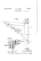
- BUILDERS HARDWARE Filed Sept. 2l, 1928 2 Sheets-Sheet 2 nr@ l Y Pmd Mu. 29', 1932 '.PATENT. oFrlcE' navman. Johnson, or wnnm'rxn, rnnnrora4 V BUILDni-zs Y Application led September My invention relates lto builders hardware, and includes among its objects and ad- ⁇ v'antages the development of an improved holder of the type usually employed on doors and usually mounted overhead. l
- Figure 1 is a plan diagram of a door and door casing indicating the application th ereto of lapparatus according to the invention
- Figure 2 is a vertical section through the middle pivotal connection
- Figure 3 is a section on line 3-3 of Figure 1;
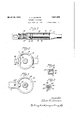
- Figure 4 is a bottom plan view of the head on the upper arm at the middle pivotal connection;
- Figure 5 is a top plan view of the opposing head on the lower arm;
- Figure 6 is a section on line 6-6 of Figure1 4 with the heads in assembled positions;
- the rigid arms 10 and 12 are connected at their adjacent ends by v the middle pivot 14.
- the pivotal connection at this point is in the form of a bolt having threaded engagement at 16 with the head 1 ofthe lower arm 12, but having a smooth cylindrical portion passing through the head 20 of the upper arm 10.
- the bolt is fastened in place by a lock nut 22.
- the lock nut 22 When mounted overhead, the only portion of this pivotal connection accessible from below is the lock nut 22. Removal of this nut does not separate the pivotal connection, which can only be disassembled by getting at the up er end of the bolt 14. This materially re uces the ease with which a mischiefmaker could .separate the two arms.
- the free ends of the arms 10 and 12 are pivotally connected to the door-supporting structure or casing and the door itself, as at 24 and 26.
- One of these pivots is farther a1, 192s. -sgnal 1ro. soms?.
- Latching means are provided for latching the parts in position to hold the door open.
- the lower head carries a tubular housin 30 for the locking' bolt 32.
- the upper washer 38 bears against the cross-pin 40 in the bolt 32, andthe lower washer rides on the retaining nut 42.
- An upwardly extending lu 44 on the arm 12 is positioned in the path o a downwardly extending lug 46 o n the edge of the head 20. This limits the straightenm ,movement to v the angularl 'relationshi iini lines in Figure 1.
- the same 1device may be mounted on either right-hand 75 or left-hand doors.
- Spaced holesv 48 in the lower face of the head 20 form sockets for lreceiving the bolt 32 to latch the parts in theV I position shown .in Fi re 1, or in the corresponding position with the lu 46 on the 80 other side of the lug 44 in case t e door ha pens to be hinged the other Way.
- the upper end of the bolt 32 rides f on the rim 50 of the head 20.
- the sprin y 36 Upon move- 85 ment to the position of Figure 1, the sprin y 36 will snap the bolt up into the posi ion o Figure 2 and hold the parts against movement in either direction.
- the user may fasten the door o en 1 11 the position of Figure 1, or, when the oor 1s closed he may position the bolt in the position of Figure 7 and the first person opening the door will cause it to become fastened in open position.
- This is an advantage in theatres and other public buildings where the caretaker anticipates the exit of a lar e number of people at a certain time, and t e door .should be held open at that time but not before.
- the arm 12 terminates in a cylindrical portion 60 housed inV a sleeve 62.
- the pivotal 1 'connection at 26 is by means of an ear 64 on the end of the sleeve 62.
- a fairly stili' compression spring 66 Abutment at one end is provided by a ring 68 bearing against a cross-pin 70 in the cylindrical portion 60, and at the other end by a retaining ring 72 threaded into the end of 376 ino erative.
- the outer surface of the retainer 72 is preferably Hush with the sleeve 62 and smooth.
- an shock absor 1n washer- 76 of suitable material such as toug v leather.'A
- the heads 18 and 20 are rovided with annular depressions at 78 an 80 forming a storage receptacle for lubricant.
- the upper head is drilledwith an oil hole 82. This hole preferably -laps over sli htly on the rim 84 of the lowerlhead, so that t e in'ection of lubricant through it will deposit a lm on.'
- Suitable lubricant up to the levell of the upper face of thelower head may be injected through the oil hole 82, and the quantity thus stored isv suflicient to keep the parts 4well lubricated over a long period of time.
- a door holder comprising, in combination, two arms pivoted to each other and to a door and door frame, the pivotal connection between said arms comprising heads on the ends of said arms, a latching bolt movable through thelower head near the outer periphery thereof, lugs on said heads for holding said arms out of alignment when moved toward alignment in either direction, two sockets in the upper head for receiving the end of said bolt when said lugs are in abutment on either side, said upper head having a smooth annular ortion around the remainder of its perip ery slidable on the end of said bolt, spring means urging said bolt to latching position, and manually operable catch means for rendering said spring means inoperative.
- a door holder comprising, in combination, two arms pivoted to each other and to a door and door frame, the pivotal connection between. said arms comprising Superposed heads on the ends of said arms, a pintle coaxial with both heads and threaded through the lower one, a lock nut threaded on said pintle below said lower head, the upper face of said lower head having an annular depression for retaining lubricant, the lower face of said upper head having a similar depression, said upper head having an oil hole positioned partly above the outer rim of said i lower head and partly above the depression in said lower head.
- a door holder in combination: piving said locking member into locking when said arms are moved to either stopped 'tion position; said member and the socket-meanscarrying arm being shaped to render locking adjacent the pivotal axis;- interengaging means on said arms for limiting their movement toward that position of alignment wherein the arms extend oppositely from the pivotal axis, said means stopping the arms 1n an angular position before ahgnment is reached; a locking member carried on one of said arms; socket means in the other arm' for receiving said' loclcing'member only in I that position inthe range -of movement of the arms wherein the arms are substantially in stopped position; and means for automatically moving said locking member into locking position when said arms are' moved to such a stopped position; said member and the socket-means-carrying arm being shaped to render locking engagement impossible at any4 other position in the range of movement of said arms.
- ivoted arms having opposite bearing sur aces Vadjacent the. pivotal axis; interengaging means on said arms for limiting their movement toward that position of alignment wherein the arms extend oppositely from the pivotal axis, said means stopping the arms in an angular position before alignment is reached, on thatside of alignment corresponding to the swing of the door on which the holder is installed; a locking member carried on one of said arms; socket means inthe other arm for receiving said locking member only in those positions of the arms, one on either side of ahgnment, wherein the arms are substantially in stopped position; and means for automatically mov-
Description
March 29, 1932. E. H. `JOHNSON BUILDERS HARDWARE Filed Sepk. 21, 1928 2 Sheets-Sheet l March 29, 1932. E H. JQHNSON 1,851,630
BUILDERS HARDWARE Filed Sept. 2l, 1928 2 Sheets-Sheet 2 nr@ l Y Pmd Mu. 29', 1932 '.PATENT. oFrlcE' navman. Johnson, or wnnm'rxn, rnnnrora4 V BUILDni-zs Y Application led September My invention relates lto builders hardware, and includes among its objects and ad- `v'antages the development of an improved holder of the type usually employed on doors and usually mounted overhead. l
.Inthe accompanying drawings, y Figure 1 is a plan diagram of a door and door casing indicating the application th ereto of lapparatus according to the invention; Figure 2 is a vertical section through the middle pivotal connection;
` Figure 3 is a section on line 3-3 of Figure 1;
Figure 4 is a bottom plan view of the head on the upper arm at the middle pivotal connection; v
Figure 5 is a top plan view of the opposing head on the lower arm; v Figure 6 is a section on line 6-6 of Figure1 4 with the heads in assembled positions;
an v 7 Figure 7 is a section on line 7-7 of Figure 2.
In the embodiment of the -invention selected for illustration, the rigid arms 10 and 12 are connected at their adjacent ends by v the middle pivot 14. The pivotal connection at this point is in the form of a bolt having threaded engagement at 16 with the head 1 ofthe lower arm 12, but having a smooth cylindrical portion passing through the head 20 of the upper arm 10. The bolt is fastened in place by a lock nut 22. When mounted overhead, the only portion of this pivotal connection accessible from below is the lock nut 22. Removal of this nut does not separate the pivotal connection, which can only be disassembled by getting at the up er end of the bolt 14. This materially re uces the ease with which a mischiefmaker could .separate the two arms.
The free ends of the arms 10 and 12 are pivotally connected to the door-supporting structure or casing and the door itself, as at 24 and 26. One of these pivots is farther a1, 192s. -sgnal 1ro. soms?.
ter clearance for the useI of a convenientsize and shape of casting or the pivotal connec- 5o ions.
Latching means are provided for latching the parts in position to hold the door open. A Lhave illustrated latching means associated w1th the middle pivot 14. For this purpose 55 the adjacent ends of the arms 10 and 12 are enlarged to form the flat heads 18 and 20. The lower head carries a tubular housin 30 for the locking' bolt 32. This bolt`sl1des through a suitable bore at 34 and is urged e0 into the position shown in Figure 2 by a suitable coil spring 36 provided with end abutment washers 38. The upper washer 38 bears against the cross-pin 40 in the bolt 32, andthe lower washer rides on the retaining nut 42.
An upwardly extending lu 44 on the arm 12 is positioned in the path o a downwardly extending lug 46 o n the edge of the head 20. This limits the straightenm ,movement to v the angularl 'relationshi iini lines in Figure 1. By p acing the lug 44 on the center line of the'arm 12 and the lug 46 on the center line of the a'rm 10 and making the lugs of the right dimensions, the same 1device may be mounted on either right-hand 75 or left-hand doors. Spaced holesv 48 in the lower face of the head 20 form sockets for lreceiving the bolt 32 to latch the parts in theV I position shown .in Fi re 1, or in the corresponding position with the lu 46 on the 80 other side of the lug 44 in case t e door ha pens to be hinged the other Way. When t e parts are in any position other than that of Figure 1, the upper end of the bolt 32 rides f on the rim 50 of the head 20. Upon move- 85 ment to the position of Figure 1, the sprin y 36 will snap the bolt up into the posi ion o Figure 2 and hold the parts against movement in either direction.
I have provided manually adjustable means l.
cated in full n l venience in retaining the parts `in this position, I prefer to provide sockets 58 for receiving the ends of the pin 54 to prevent accidental rotation of the handle 56 back to the position of Figure 7.
Thus the user may fasten the door o en 1 11 the position of Figure 1, or, when the oor 1s closed he may position the bolt in the position of Figure 7 and the first person opening the door will cause it to become fastened in open position. This is an advantage in theatres and other public buildings where the caretaker anticipates the exit of a lar e number of people at a certain time, and t e door .should be held open at that time but not before.
The openin movement of the door to the position of Figure 1, either by the caretaker or by someone else, is apt to be made with conslderable force, especially assuch. doors are usually equipped with a closing spring. As such a closing spring is old and well known in the prior art and per se forms no part ofv the present invention, I have not encumbered the drawings with the illustration of any particular type of spring. It may be understood that the spring is to be associated with the hinge 28 or with either of the pivots 24 or 26 or with the pivot 14. It would be equally effective in any one of the positions mentioned, although the customary positions are at the hinge 28 and at the pivot 24.
If the door is being subjected to considerable force or moving with considerable speed when it arrives at the position of Figure 1, the sudden interruption of the opening movement by the latching of the parts is apt to produce a severe shock that might damage the parts. The commonest form of damage is tearing out the supports for the pivotal connections at 24 and 26.
To relieve the abruptness of this action, I have formed the arm 12 in two telescoping portions with shock absorbing means interposed between them. Referring to Figure 3, the arm 12 terminates in a cylindrical portion 60 housed inV a sleeve 62. The pivotal 1 'connection at 26 is by means of an ear 64 on the end of the sleeve 62. Between the cylindrical portion 60 and the sleeve 62 I position a fairly stili' compression spring 66. Abutment at one end is provided by a ring 68 bearing against a cross-pin 70 in the cylindrical portion 60, and at the other end by a retaining ring 72 threaded into the end of 376 ino erative. Re-
Athe sleeve 62. The outer surface of the retainer 72 is preferably Hush with the sleeve 62 and smooth. Between the end of the re-` tiner 72 and the abutment shoulder 74 at the base of the cylindrical ortion 60 I osi-- tion a sound deadening an shock absor 1n washer- 76 of suitable material such as toug v leather.'A
I have provided means for storing a sup-Y ply of lubricant at the middle pivot 14. For thls purpose,.the heads 18 and 20 are rovided with annular depressions at 78 an 80 forming a storage receptacle for lubricant. The upper head is drilledwith an oil hole 82. This hole preferably -laps over sli htly on the rim 84 of the lowerlhead, so that t e in'ection of lubricant through it will deposit a lm on.'
the rim 84 which slides in contact with the lip 50. Suitable lubricant up to the levell of the upper face of thelower head may be injected through the oil hole 82, and the quantity thus stored isv suflicient to keep the parts 4well lubricated over a long period of time.
Without further elaboration, the forego- I between said arms ,comprising enlarged.
superposedl flat heads on the ends of said arms, apintle lcoaxial with both heads and threaded through the lower one, a lock nut threaded on said pintle below said lower head, the upper faceof said lower head having an annular depression for retaining lubricant, the lower face of saidupper head having a similardepression, said upper head having a vertical oil hole positioned partly above the outer rim of said-lower head and partly above the depression in said lower head, a vertical latching bolt movable upwardly through said lower head near the outer periphery thereof, lugs on said heads in .alignment with said arms for holding saidV arms out of alignment Whenmoved toward alignment in either direction, two sockets in said upper head for receiving the end of said bolt when said lugs are in abutment on either side, said upper head having a smooth annular portion around the remainder of its periphery slidable on the end of said bolt, spring means urging said bolt to latching position, and manually operable catch means for rendering said spring means inoperative.
2. A door holder comprising, in combination, two arms pivoted to each other and to a door and door frame, the pivotal connection between said arms comprising heads on the ends of said arms, a latching bolt movable through thelower head near the outer periphery thereof, lugs on said heads for holding said arms out of alignment when moved toward alignment in either direction, two sockets in the upper head for receiving the end of said bolt when said lugs are in abutment on either side, said upper head having a smooth annular ortion around the remainder of its perip ery slidable on the end of said bolt, spring means urging said bolt to latching position, and manually operable catch means for rendering said spring means inoperative.
3. A door holder comprising, in combination, two arms pivoted to each other and to a door and door frame, the pivotal connection between. said arms comprising Superposed heads on the ends of said arms, a pintle coaxial with both heads and threaded through the lower one, a lock nut threaded on said pintle below said lower head, the upper face of said lower head having an annular depression for retaining lubricant, the lower face of said upper head having a similar depression, said upper head having an oil hole positioned partly above the outer rim of said i lower head and partly above the depression in said lower head.
4. In a door holder, in combination: piving said locking member into locking when said arms are moved to either stopped 'tion position; said member and the socket-meanscarrying arm being shaped to render locking adjacent the pivotal axis;- interengaging means on said arms for limiting their movement toward that position of alignment wherein the arms extend oppositely from the pivotal axis, said means stopping the arms 1n an angular position before ahgnment is reached; a locking member carried on one of said arms; socket means in the other arm' for receiving said' loclcing'member only in I that position inthe range -of movement of the arms wherein the arms are substantially in stopped position; and means for automatically moving said locking member into locking position when said arms are' moved to such a stopped position; said member and the socket-means-carrying arm being shaped to render locking engagement impossible at any4 other position in the range of movement of said arms.
5. In a door holder adapted to be installed on either a right-hand or a left-handdoor, in combination: ivoted arms having opposite bearing sur aces Vadjacent the. pivotal axis; interengaging means on said arms for limiting their movement toward that position of alignment wherein the arms extend oppositely from the pivotal axis, said means stopping the arms in an angular position before alignment is reached, on thatside of alignment corresponding to the swing of the door on which the holder is installed; a locking member carried on one of said arms; socket means inthe other arm for receiving said locking member only in those positions of the arms, one on either side of ahgnment, wherein the arms are substantially in stopped position; and means for automatically mov-
Priority Applications (1)
| Application Number | Priority Date | Filing Date | Title |
|---|---|---|---|
| US307387A US1851630A (en) | 1928-09-21 | 1928-09-21 | Builder's hardware |
Applications Claiming Priority (1)
| Application Number | Priority Date | Filing Date | Title |
|---|---|---|---|
| US307387A US1851630A (en) | 1928-09-21 | 1928-09-21 | Builder's hardware |
Publications (1)
| Publication Number | Publication Date |
|---|---|
| US1851630A true US1851630A (en) | 1932-03-29 |
Family
ID=23189539
Family Applications (1)
| Application Number | Title | Priority Date | Filing Date |
|---|---|---|---|
| US307387A Expired - Lifetime US1851630A (en) | 1928-09-21 | 1928-09-21 | Builder's hardware |
Country Status (1)
| Country | Link |
|---|---|
| US (1) | US1851630A (en) |
Cited By (10)
| Publication number | Priority date | Publication date | Assignee | Title |
|---|---|---|---|---|
| US2475131A (en) * | 1947-08-08 | 1949-07-05 | Om Edwards Co Inc | Window sash holder |
| US3259936A (en) * | 1964-05-05 | 1966-07-12 | Eaton Yale & Towne | Door holder and control |
| US3260545A (en) * | 1964-07-10 | 1966-07-12 | Eaton Yale & Towne | Door hold-open device |
| US3877108A (en) * | 1971-12-10 | 1975-04-15 | Schlage Lock Co | Door hold-open device |
| US4070049A (en) * | 1976-01-05 | 1978-01-24 | Brewer Jack J | Security door guard |
| US4076293A (en) * | 1974-06-17 | 1978-02-28 | Joel Valles | Door security strut |
| US4850343A (en) * | 1985-09-26 | 1989-07-25 | Standex International | Assist handle for chiropractic treatment table |
| EP1553250A1 (en) * | 2002-10-15 | 2005-07-13 | Sugatsune Kogyo Co., Ltd. | Stay |
| ITMI20102392A1 (en) * | 2010-12-23 | 2012-06-24 | Caspim S R L | MANUAL HANDLING DEVICE FOR WINDOWS, HINGED DOORS AND THE LIKE |
| US10508484B1 (en) * | 2018-06-15 | 2019-12-17 | GM Global Technology Operations LLC | Auto-lock folding prop rod |
-
1928
- 1928-09-21 US US307387A patent/US1851630A/en not_active Expired - Lifetime
Cited By (14)
| Publication number | Priority date | Publication date | Assignee | Title |
|---|---|---|---|---|
| US2475131A (en) * | 1947-08-08 | 1949-07-05 | Om Edwards Co Inc | Window sash holder |
| US3259936A (en) * | 1964-05-05 | 1966-07-12 | Eaton Yale & Towne | Door holder and control |
| US3260545A (en) * | 1964-07-10 | 1966-07-12 | Eaton Yale & Towne | Door hold-open device |
| US3877108A (en) * | 1971-12-10 | 1975-04-15 | Schlage Lock Co | Door hold-open device |
| US4076293A (en) * | 1974-06-17 | 1978-02-28 | Joel Valles | Door security strut |
| US4070049A (en) * | 1976-01-05 | 1978-01-24 | Brewer Jack J | Security door guard |
| US4850343A (en) * | 1985-09-26 | 1989-07-25 | Standex International | Assist handle for chiropractic treatment table |
| EP1553250A1 (en) * | 2002-10-15 | 2005-07-13 | Sugatsune Kogyo Co., Ltd. | Stay |
| US20060048339A1 (en) * | 2002-10-15 | 2006-03-09 | Sugatsune Kogyo Co., Ltd. | Stay |
| EP1553250A4 (en) * | 2002-10-15 | 2007-12-19 | Sugatsune Kogyo | Stay |
| US7340801B2 (en) | 2002-10-15 | 2008-03-11 | Sugatsune Kogyo Co., Ltd. | Stay |
| ITMI20102392A1 (en) * | 2010-12-23 | 2012-06-24 | Caspim S R L | MANUAL HANDLING DEVICE FOR WINDOWS, HINGED DOORS AND THE LIKE |
| EP2469000A1 (en) * | 2010-12-23 | 2012-06-27 | Caspim S.r.l. | Device for manually moving shutters, swing doors and the like |
| US10508484B1 (en) * | 2018-06-15 | 2019-12-17 | GM Global Technology Operations LLC | Auto-lock folding prop rod |
Similar Documents
| Publication | Publication Date | Title |
|---|---|---|
| US1851630A (en) | Builder's hardware | |
| US2290331A (en) | Door check for automobiles | |
| US2166746A (en) | Overhead operating garage door construction | |
| US2132266A (en) | Gooseneck concealed hinge | |
| US1841890A (en) | Window lock | |
| US2724143A (en) | Door checking and holding device | |
| US1966205A (en) | Builder's hardware | |
| US2259821A (en) | Doorstop | |
| US2812536A (en) | Hinge and ball hold-open | |
| US1893592A (en) | Hinge | |
| US2078303A (en) | Door hinge | |
| US2892209A (en) | Combined hinge and hold-open device for closure members | |
| US2046612A (en) | Dovetail | |
| US1573512A (en) | Door holder | |
| US2661495A (en) | Double-acting gravity hinge | |
| US2263782A (en) | Combination door and supporting structure | |
| US2335201A (en) | Hinge | |
| US2219821A (en) | Door opening device | |
| US1768161A (en) | Gravity hinge | |
| US2213461A (en) | Automobile door support | |
| US1698390A (en) | Hinge | |
| US2856629A (en) | Hold open door hinge | |
| US1542113A (en) | Disappearing step | |
| US2791794A (en) | Automobile door hinge | |
| US2167585A (en) | Hinge |