US1852218A - Method of and apparatus for feeding molten glass - Google Patents
Method of and apparatus for feeding molten glass Download PDFInfo
- Publication number
- US1852218A US1852218A US67574A US6757425A US1852218A US 1852218 A US1852218 A US 1852218A US 67574 A US67574 A US 67574A US 6757425 A US6757425 A US 6757425A US 1852218 A US1852218 A US 1852218A
- Authority
- US
- United States
- Prior art keywords
- glass
- outlet
- implement
- container
- speed
- Prior art date
- Legal status (The legal status is an assumption and is not a legal conclusion. Google has not performed a legal analysis and makes no representation as to the accuracy of the status listed.)
- Expired - Lifetime
Links
Images
Classifications
-
- C—CHEMISTRY; METALLURGY
- C03—GLASS; MINERAL OR SLAG WOOL
- C03B—MANUFACTURE, SHAPING, OR SUPPLEMENTARY PROCESSES
- C03B7/00—Distributors for the molten glass; Means for taking-off charges of molten glass; Producing the gob, e.g. controlling the gob shape, weight or delivery tact
- C03B7/08—Feeder spouts, e.g. gob feeders
- C03B7/084—Tube mechanisms
-
- C—CHEMISTRY; METALLURGY
- C03—GLASS; MINERAL OR SLAG WOOL
- C03B—MANUFACTURE, SHAPING, OR SUPPLEMENTARY PROCESSES
- C03B7/00—Distributors for the molten glass; Means for taking-off charges of molten glass; Producing the gob, e.g. controlling the gob shape, weight or delivery tact
- C03B7/08—Feeder spouts, e.g. gob feeders
- C03B7/086—Plunger mechanisms
Definitions
- My invention relates to the art of feeding molten glass, and more particularly to the separation of molten glass into mold charges for use in glassware shaping machines-
- the invention has particular reference to glass feeders in which the glass is discharged from an outlet in a container under the influence of forces acting on the glass in the container, and the primary object of my invention is to for utilizing centrifugal force as an agent for controlling the rate at which the glass is discharged.
- This object is accomplished by providing an implement which projects into the glass near the container outlet, and rotating the implement at constant or periodically varying speed, so as to cause a rotative movement of the glass adjacent to the outlet, this movement developing suflicient centrifugal force in the glass to counteract the natural force of gravity and thereby to retard, or even reverse, the movement of the glass in and below the outlet.
- the rate of discharge is controlled by maintaining constant centrifugal force on the glass by rotating the implement at a uniform but adjustable speed.
- the apparatus may also be caused to deliver glass intermittently in the form of mold charges of predetermined size and and shape, in which case the contrifugal force exerted on the glass at the outlet is periodically varied to regulate the size and shape of the charges.
- Such periodic variation of centrifugal force applied to the glass may be obtained by advancing and retarding the implement, rotating at uniform speed, toward and from the outlet; or by maintaining the implement at a constant distance from the outlet and periodically varying the rotational speed thereof in accordance with the required centrifugal forces necessary to interrupt the discharge.
- Another object of the invention is to provide a glass feeder of the character designated in which a portion of the glass in the container is rotated prior to being discharged from the outlet, and is thereby mixed and rendered thoroughly homogeneous.
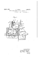
- Figure 1 is a view in elevation, showingparts in section, of a centrifugal glass feeding apparatus constructed in accordance with the present invention.
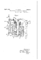
- Fig. 2 is a similar view of a modification in which a rotary tube is employed as the centrifugal member and is arranged to cooperate with a reciprocable plunger in discharging mold charges of predetermined size and shape.
- a glass feeder arranged to feed mold charges of glass by means of a rotary implement 10 positioned near, and in axial alignment with, an outlet 11 located in the bottom of a container 12, which may be a forehearth connected to a glass melting tank, not shown.
- the discharged glass is separated into mold charges by cooperating shear blades 13.13.
- the container 12 is enclosed in a metalic casing 14 which may serve to retain heat-insulating material and also to provide a support.
- the feeder operating mechanism which is carried by a suitable frame 15 mounted on the casin Centrifugal. force for controlling the rate at which the glass is discharged from the outlet 11 is developed by rotating the implement 10 at a speed which may be varied to produce the desired feeding results.
- speeds may be obtained by any suitable speed-ch ange device, as for example by a friction device, which includes a large disc 16 operatively connected to the implement 10 and a relatively small driving disc17 operated from an independent source of power as more fully described below.
- a friction device which includes a large disc 16 operatively connected to the implement 10 and a relatively small driving disc17 operated from an independent source of power as more fully described below.
- different speeds are imparted to the implement 10 by moving the driving disc 17 radially with respect to the driven disc 16, thus causing the implement to set up the desired centrifugal forces in the glass.
- the mechanism for supporting and rotating the implement 10 includes a bevel gear 20 mounted in a bearing 21 on the feeder frame.
- the implement 10 may be adjusted vertically,
- I so as to change its position relative to the outamsm may let, in any suitable manner as, for example, by splinin a rod 22 to the hub of the bevel gear 20 by a ey 23 and a keyway 24 formed in the rod.
- the upper portion of the rod 22 protrudes through the bevel gear 20 and is threaded to receive a win nut 25 and an associated set nut 26.
- the implement 10 is secured to the lower end of the rod 21 by a chuck 27.
- the implement may be raised or lowered relative to the outlet, to adjust the size of the flow passage between the implement and the walls of the outlet.
- the implement 10 is shown as havin an enlarged lower portion 10 which provldes for an annular flow passage 28 to conduct the glass to the outlet from the supply in the container. This enlargement better enables the implement to exert the desired rotative effect on the glass adjacent to the implement and the outlet, and thereby more accurately controls the discharge of the glass.
- the various speeds at which the implement is rotated are obtained by a friction speed-change mechanism in which the driving disc is moved radially of the driven disc.
- the driven disc 16 is mounted on a shaft 30 which connects with the bevel gear 20 through a gear 31, and the driving frlction disc 17 is connected directly to a suitable power unit indicated at 32, which may be a constant speed motor.
- This power unit is mounted for reciprocatory motion in suitable guideways 33 and is reciprocated by a cam 18 which acts through a pivotally mounted cam roll lever 34 and a link 35 connected to the power unit support.
- the cam 18 is rotated b a power shaft 19, which may also serve to rive the operating mechanism of the shears 13.
- Such shear-operating mechbe similar to that shown and described in my Patent No. 1,760,254, granted May 27, 1930. I
- the glass in the container flows to the outlet 11 through the open passage 28, and the normal gravity flow may be regulated by changing the slze of the flow passage by the vertical adjustment of the implement 10.
- Proper flow of glass from the outlet isfur- 'ther controlled by rotating the implement sov that the lass in the container near the outlet is rotat
- This rotation of the glass around the outlet has two principal effects, namely, to mix the glass thoroughly and to develop sufiicient centrifugal force to modify substantially the rate at which the glass is discharged from the outlet.
- the issuing glass is preferably formed into suspended mold charges of the desired size and shape by periodically increasing and decreasing, or even stopping, the rotational speed of the im- 1 I d epends upon the, extent to plement to apply, at regular intervals, the required centrlfu a1 forces to counteract, either partly or comp etely, the gravitational forces acting on the glass.
- the speed of the implement may be varied as desired, by suitably sha ing the cam 18, so as to control the shape 0 the upper, lower and intermediate parts of each individual mold char e.
- the rotary implement is shown as a tube 40 surrounding a reciprocable plunger 41, projecting into the container 12 in axial ahgnment am able to .obtain with the outlet 11.
- the plunger 41 may be mounted and reciprocated as shown in my above-mentioned Patent No. 1,760,254.
- the tube 40 is mounted in a stationary bracket 42 by means of a screw-threaded collar 42a.
- the tube may thus be vertically adjusted relative to the outlet to regulate the size of the mold charges, but this regulation is secondary to the speed of rotation of the tube in controlling the rate of discharge of glass from the feeder outlet.
- the tube is rotated from a motor 43,
- gears 44, 45, and 45a which are driven by friction discs 46 and 47 arranged and operated in a manner similar to the speed-change device shown in Fig. 1.
- the motor 43 carrying the friction drive gear 46 is moved relative to the driven disc 47 by a manually operated adjustin device 48 attached to the feeder frame, w 'c moves the motor in suitable ways so as to move the driving disc 46 toward and from the center of the disc 47 If it is desired to stop the rotation of the tube 40, the disc 46 may be lowered until it passes off the disc 47 upon a. freely rotatable ring 49 in the same plane as the disc 47. r
- the amount of glass admitted to the outlet is controlled by maintaining the tube at a suitable distance from the outlet, and by rotatin the tube so as to set up suflicient centri igal forces to counteract the force of gravity to the desired extent.
- the 6 shape imparted tothe issuing charges is determined by the reciprocation of the lunger 40, in the manner set forth in my i atent
- Another variant form of this invention 10 consists in providing a solid implement, like the headed implement 10 of 'Fi 1 or the tapering-ended implement 41 of ig. 2, and rotating this implement constantly in the glass without vertical movement of the implement.
- the rotary flow-controlling implements occupy the same general position relative to the forehearth outlet and produce the same rotative movement of the glass, which, in addition to developing forces in the glass that are effectively utilized to control its flow from the outlet, serve to thoroughly mix the glass just prior to its discharge and cause it to be delivered in a homogeneous state.
- the method of feeding molten glass from an outlet in a stationary container which comprises establishing a gravity flow of glass from the outlet and retarding the flow by centrifugal force applied to the glass by rotating an internal portion of the body of glass within the container about the axis of the outlet at a speed sufficient periodically to overcome the action of gravity.
- the method of discharging mold charges from a container having a submerged outlet and a flow-controlling implement arranged to cooperate with a wall of the containerto form a passageway communicatingwith the outlet which comprises the steps of causing glass to flow from the source of supplyin through the outlet, maintaining a movement of a wall of said passageway in a direction to apply a force to the issuing glass in oppos tion to the force of gravity, periodically in creasing the speed of movement of thewall
- Such an arrangement is suitable for deliyere.
- mechamcal means operating by a continuous movement within the glass to apply arestraining force effective periodically to practically stop the flow of glass through the outlet, means for periodically applying an expelling force to the glass in the container, and means for periodically severing the issuing glass.
- Apparatus for separating molten glass into mold charges comprising a container having a submerged outlet, a rotary flowcontrolling implement projecting into the glass in axial alignment with the outlet, said implement being adapted to apply a centrifugal action to the glass at theoutlet for controlling flow of lass through the outlet, means for periodically varying the centrifugal action by changing the speed of rotation of the implement without change of direction of rotation of the implement, whereby mold charges of glass periodically issue from the outlet, and means for periodically severing the issuing glass.
- the method of feeding molten glass in mold charges performed while suspended from an outlet of a glass container which comprises causing the glass to flow through a the outlet by gravity, applying to the glass N above the outlet a periodically varying centrifugal force without rotating the container to vary the rate of issuance of glass through the outlet so thatthe suspended glass is given a predeterminedshape, and periodically separating the shaped glass from the glass in the container.
- the method of forming mold charges of molten glass issuing by gravity from a submerged outlet of a non-rotating glass container which comprises causing a centrifugal force in the molten glass above the outlet sufii cient to retard the gravity flow of glass through the outlet, varying the centrifugal force to effect shaping of the glass suspended from the outlet, said centrifugal force having a maximum flow retarding effect when the glass suspended from the outlethas' at.- tained a desired shape, and then being efi'ective to interrupt said flow, and severing the shaped glass below the outlet at a timerelated to the time of application of the maximum centrifugal force above the outlet.
- the method of forming mold charges of molten glass which. comprises discharging glass through an outlet of a container under theforce of gravity modified by centrifugal force set up in the glass above the outlet by,
- a method of feeding molten glass from a submerged outlet of a glass container to produce mold charges periodically severed from molten glass issuing by gravity from the outlet, the step which comprises rotating an implement immersed in the glass in such manner as to periodically cause a centrifugal force on the glass in the container adjacent to the outlet sufficient to retract the glass stubs after the mold charges have been severed therefrom.
- the method which consists in causing molten glass to flow b gravity from an outlet in a container an periodically rotating 9. portion of the body of glass Within the container about the axis of the outlet by a force applied directly to the glass adjacent to the outlet and at a speed to overcome the increasing the speed of rotation sufiiciently to thereby overcome the action of gravity.
- the method which consists in causing glass to flow from a supply body through a passageway and downward through an outlet, maintaining a continuous movement of one of the walls of said passageway .
- said applied force being periodically varied in degree and suflicient to substantially overcome the force of gravity and stop the flow through said outlet.
Description
April 1932- K. E. PEILER 1,852,218
METHOD OF AND APPARATUS FOR FEEDING MOLTEN GLASS Filed Nov. 7, 1925 2 Sheets-Sheet l Fay.
[72 $672607": ZarZZTPez'Zer Azzy.
April 5, 1932. K E. PEILER 1,852,218
METHOD OF AND APPARATUS FOR FEEDING MOLTEN GLASS Filed 1925 2 Sheets-Sheet 2 Fig. 2
Ara?
Patented Apr. 5, 1932 UNITED STATES PATENT OFFICE KARL E. PEIIER, OI WEST HARTFORD, CONNECTICUT, ASSIGNOR TO HARTFORD-EMPIRE COMPANY, OF HARTFORD, CONNECTIC UT, A CORPORATION OF DELAWARE METHOD OF AND APPARAT US FOR- FEEDING MOI-TEN GLASS Application filed November 7, 1925. Serial No. 67,574.
My invention relates to the art of feeding molten glass, and more particularly to the separation of molten glass into mold charges for use in glassware shaping machines- The invention has particular reference to glass feeders in which the glass is discharged from an outlet in a container under the influence of forces acting on the glass in the container, and the primary object of my invention is to for utilizing centrifugal force as an agent for controlling the rate at which the glass is discharged.
This object is accomplished by providing an implement which projects into the glass near the container outlet, and rotating the implement at constant or periodically varying speed, so as to cause a rotative movement of the glass adjacent to the outlet, this movement developing suflicient centrifugal force in the glass to counteract the natural force of gravity and thereby to retard, or even reverse, the movement of the glass in and below the outlet.
In utilizing the apparatus as a stream feeder, the rate of discharge is controlled by maintaining constant centrifugal force on the glass by rotating the implement at a uniform but adjustable speed. The apparatus may also be caused to deliver glass intermittently in the form of mold charges of predetermined size and and shape, in which case the contrifugal force exerted on the glass at the outlet is periodically varied to regulate the size and shape of the charges. Such periodic variation of centrifugal force applied to the glass may be obtained by advancing and retarding the implement, rotating at uniform speed, toward and from the outlet; or by maintaining the implement at a constant distance from the outlet and periodically varying the rotational speed thereof in accordance with the required centrifugal forces necessary to interrupt the discharge.
Another object of the invention is to provide a glass feeder of the character designated in which a portion of the glass in the container is rotated prior to being discharged from the outlet, and is thereby mixed and rendered thoroughly homogeneous.
provide a method and apparatus These and other objects will be more manifest from the following specification taken in connection with the accompanying drawings, in which Figure 1 is a view in elevation, showingparts in section, of a centrifugal glass feeding apparatus constructed in accordance with the present invention; and
Fig. 2 is a similar view of a modification in which a rotary tube is employed as the centrifugal member and is arranged to cooperate with a reciprocable plunger in discharging mold charges of predetermined size and shape.
In Fig. 1 of the drawings, there is shown a glass feeder arranged to feed mold charges of glass by means of a rotary implement 10 positioned near, and in axial alignment with, an outlet 11 located in the bottom of a container 12, which may be a forehearth connected to a glass melting tank, not shown. The discharged glass is separated into mold charges by cooperating shear blades 13.13. The container 12 is enclosed in a metalic casing 14 which may serve to retain heat-insulating material and also to provide a support. for the feeder operating mechanism which is carried by a suitable frame 15 mounted on the casin Centrifugal. force for controlling the rate at which the glass is discharged from the outlet 11 is developed by rotating the implement 10 at a speed which may be varied to produce the desired feeding results. These speeds may be obtained by any suitable speed-ch ange device, as for example by a friction device, which includes a large disc 16 operatively connected to the implement 10 and a relatively small driving disc17 operated from an independent source of power as more fully described below. In this device, different speeds are imparted to the implement 10 by moving the driving disc 17 radially with respect to the driven disc 16, thus causing the implement to set up the desired centrifugal forces in the glass.
The mechanism for supporting and rotating the implement 10 includes a bevel gear 20 mounted in a bearing 21 on the feeder frame. The implement 10 may be adjusted vertically,
I so as to change its position relative to the outamsm may let, in any suitable manner as, for example, by splinin a rod 22 to the hub of the bevel gear 20 by a ey 23 and a keyway 24 formed in the rod. The upper portion of the rod 22 protrudes through the bevel gear 20 and is threaded to receive a win nut 25 and an associated set nut 26. The implement 10 is secured to the lower end of the rod 21 by a chuck 27. Thus the implement may be raised or lowered relative to the outlet, to adjust the size of the flow passage between the implement and the walls of the outlet. The implement 10 is shown as havin an enlarged lower portion 10 which provldes for an annular flow passage 28 to conduct the glass to the outlet from the supply in the container. This enlargement better enables the implement to exert the desired rotative effect on the glass adjacent to the implement and the outlet, and thereby more accurately controls the discharge of the glass.
As stated above, the various speeds at which the implement is rotated, are obtained by a friction speed-change mechanism in which the driving disc is moved radially of the driven disc. In the illustrated embodiment of the invention, the driven disc 16 is mounted on a shaft 30 which connects with the bevel gear 20 through a gear 31, and the driving frlction disc 17 is connected directly to a suitable power unit indicated at 32, which may be a constant speed motor. This power unit is mounted for reciprocatory motion in suitable guideways 33 and is reciprocated by a cam 18 which acts through a pivotally mounted cam roll lever 34 and a link 35 connected to the power unit support. The cam 18 is rotated b a power shaft 19, which may also serve to rive the operating mechanism of the shears 13. Such shear-operating mechbe similar to that shown and described in my Patent No. 1,760,254, granted May 27, 1930. I
In the operation of the apparatus described above, the glass in the container flows to the outlet 11 through the open passage 28, and the normal gravity flow may be regulated by changing the slze of the flow passage by the vertical adjustment of the implement 10. Proper flow of glass from the outlet isfur- 'ther controlled by rotating the implement sov that the lass in the container near the outlet is rotat This rotation of the glass around the outlet has two principal effects, namely, to mix the glass thoroughly and to develop sufiicient centrifugal force to modify substantially the rate at which the glass is discharged from the outlet.
Having thusadjusted the implement to establish the desired flow of glass, the issuing glass is preferably formed into suspended mold charges of the desired size and shape by periodically increasing and decreasing, or even stopping, the rotational speed of the im- 1 I d epends upon the, extent to plement to apply, at regular intervals, the required centrlfu a1 forces to counteract, either partly or comp etely, the gravitational forces acting on the glass. In the intervals between the maximum and minimum development of centrifugal force, the speed of the implement may be varied as desired, by suitably sha ing the cam 18, so as to control the shape 0 the upper, lower and intermediate parts of each individual mold char e. It will be obvious that the rate at whic any part of a mold charge issues from the outlet, and consequentthe diameter of that part of the charge, which the normal gravity flow is reduced by the action of centrifu al force. By thus varying the centrifugal orces acting on the glass during the delivery of a mold charge, much the same effects, in shaping the charge,
' as are produced b a vertically reciprocating plunger in the fee er shown in my above-mentioned Patent No. 1,760,254.
I have shown and described a convenient mechanism for imparting variable speeds to the rotary implement, but it is obvious that any other system of speed change devices may be employed for this purpose.
In the modification shown in Fig. 2, the rotary implement is shown as a tube 40 surrounding a reciprocable plunger 41, projecting into the container 12 in axial ahgnment am able to .obtain with the outlet 11. The plunger 41 may be mounted and reciprocated as shown in my above-mentioned Patent No. 1,760,254. The tube 40 is mounted in a stationary bracket 42 by means of a screw-threaded collar 42a. The tube may thus be vertically adjusted relative to the outlet to regulate the size of the mold charges, but this regulation is secondary to the speed of rotation of the tube in controlling the rate of discharge of glass from the feeder outlet. The tube is rotated from a motor 43,
or other suitable source of power, by gears 44, 45, and 45a, which are driven by friction discs 46 and 47 arranged and operated in a manner similar to the speed-change device shown in Fig. 1. The motor 43 carrying the friction drive gear 46 is moved relative to the driven disc 47 by a manually operated adjustin device 48 attached to the feeder frame, w 'c moves the motor in suitable ways so as to move the driving disc 46 toward and from the center of the disc 47 If it is desired to stop the rotation of the tube 40, the disc 46 may be lowered until it passes off the disc 47 upon a. freely rotatable ring 49 in the same plane as the disc 47. r
- The structural details for rotatably mounting the tube 40 are substantially as set forth in my Patent No. 1,735,837, granted Nov. 12,1929, and are therefore not described in detail herein.
In operating the apparatus of Fig. 2, the amount of glass admitted to the outlet is controlled by maintaining the tube at a suitable distance from the outlet, and by rotatin the tube so as to set up suflicient centri igal forces to counteract the force of gravity to the desired extent. In such apparatus, the 6 shape imparted tothe issuing charges is determined by the reciprocation of the lunger 40, in the manner set forth in my i atent Another variant form of this invention 10 consists in providing a solid implement, like the headed implement 10 of 'Fi 1 or the tapering-ended implement 41 of ig. 2, and rotating this implement constantly in the glass without vertical movement of the implement.
ing the glass in a constant stream, at a rate Y which may be accurately controlled by adjusting the speed of rotation of the implement. Such speed-changing means may be similar to the manual speed-changing device shown in Fig. 2 for operating the tube 40. In both of the structures herein shown, the rotary flow-controlling implements occupy the same general position relative to the forehearth outlet and produce the same rotative movement of the glass, which, in addition to developing forces in the glass that are effectively utilized to control its flow from the outlet, serve to thoroughly mix the glass just prior to its discharge and cause it to be delivered in a homogeneous state.
I am aware that glass feeders have heretofore been provided with rotary implements which, by their rotation, impart rotary movement to the glass for the purpose of mixing the glass and increasing its homogeneity. The present invention adds to this mixing effect the further effect of centrifugal force which, although theoretically present to a small extent in the prior rotary-implement devices, has not heretofore been employed to produce any useful result.
I claim as my invention:
1. The method of feeding molten glass from an outlet in a stationary container, which comprises establishing a gravity flow of glass from the outlet and retarding the flow by centrifugal force applied to the glass by rotating an internal portion of the body of glass within the container about the axis of the outlet at a speed sufficient periodically to overcome the action of gravity.
2. The method of discharging mold charges from a container having a submerged outlet and a flow-controlling implement arranged to cooperate with a wall of the containerto form a passageway communicatingwith the outlet, which comprises the steps of causing glass to flow from the source of supplyin through the outlet, maintaining a movement of a wall of said passageway in a direction to apply a force to the issuing glass in oppos tion to the force of gravity, periodically in creasing the speed of movement of thewall Such an arrangementis suitable for deliyere.
the container through the passageway and to temporarily stop the gravity flow of glass from the outlet and periodically severing the I issued glass.
3. In apparatus for feeding molten glass,
the comblnation of a container for the glass havin a submerged outlet opening in the bottom t ereof, a rotary implement extending downward into the glass over the outlet, and means to rotate said implement about a vertical axis at a speed sulficient periodically to overcome by centrifugal force the effect of gravity on the glass at the outlet.
4. In apparatus for feeding molten glass,
the combination...of .a container for molten glass having a submerged outlet, mechamcal means operating by a continuous movement within the glass to apply arestraining force effective periodically to practically stop the flow of glass through the outlet, means for periodically applying an expelling force to the glass in the container, and means for periodically severing the issuing glass.
5. Apparatus for separating molten glass into mold charges, comprising a container having a submerged outlet, a rotary flowcontrolling implement projecting into the glass in axial alignment with the outlet, said implement being adapted to apply a centrifugal action to the glass at theoutlet for controlling flow of lass through the outlet, means for periodically varying the centrifugal action by changing the speed of rotation of the implement without change of direction of rotation of the implement, whereby mold charges of glass periodically issue from the outlet, and means for periodically severing the issuing glass.
6. The method of forming a mold charge of molten glass from a contamer having a submerged discharge outlet which comprlses controlling the issuance of glass from the outlet by rotating an implement having an end larger' in diameter than the outlet and immersed in the glass above the outlet at a speed less than that sufficient to overcome the extrusive action of gravity, increasing the speed of rotation of the implement to impart to the glass centrifugal force suflicient to overcome the gravity action, and severing the charge so formed.
7. The method of feeding molten glass in mold charges performed while suspended from an outlet of a glass container, which comprises causing the glass to flow through a the outlet by gravity, applying to the glass N above the outlet a periodically varying centrifugal force without rotating the container to vary the rate of issuance of glass through the outlet so thatthe suspended glass is given a predeterminedshape, and periodically separating the shaped glass from the glass in the container.
- 8. The method of forming mold charges of molten glass issuing by gravity from a submerged outlet of a non-rotating glass container which comprises causing a centrifugal force in the molten glass above the outlet sufii cient to retard the gravity flow of glass through the outlet, varying the centrifugal force to effect shaping of the glass suspended from the outlet, said centrifugal force having a maximum flow retarding effect when the glass suspended from the outlethas' at.- tained a desired shape, and then being efi'ective to interrupt said flow, and severing the shaped glass below the outlet at a timerelated to the time of application of the maximum centrifugal force above the outlet.
9. The method of forming mold charges of molten glass which. comprises discharging glass through an outlet of a container under theforce of gravity modified by centrifugal force set up in the glass above the outlet by,
the rotation of an implement in the glass, varying the size of different mold charges by varying the position of the rotating implement in the glass relatively to the outlet, and severing the charges so formed.
10. In apparatus for feeding molten glass, the'combination of a container for the glass having a submerged outlet opening in the :bottom thereof, a rotary implement extending downward into the glass over the outlet, andmeans to rotate said implement about a vertical axis at a speed sufficient to oppose by centrifugal force the effect of gravity on the glass at the outlet, said implement having an enlarged disk-like lower end portion having its-diameter equal to or greater than twice the diameter of the portion of the implement above said disk-like portion. 11. In a method of feeding molten glass from a submerged outlet of a glass container to produce mold charges periodically severed from molten glass issuing by gravity from the outlet, the step which comprises rotating an implement immersed in the glass in such manner as to periodically cause a centrifugal force on the glass in the container adjacent to the outlet sufficient to retract the glass stubs after the mold charges have been severed therefrom.
12. In a method of feeding molten glass I from a glass container by causing molten glass to flow from the container through a submerged outlet of the container, the step of causing a periodic reversal of direction of movement of the molten glass suspended from the outlet by a. centrifugal force applied periodically to the interior of the glass in the container by rotating an implement immersed in the glass in the container in substantial alignment with the outlet.
13. The method which consists in causing molten glass to flow b gravity from an outlet in a container an periodically rotating 9. portion of the body of glass Within the container about the axis of the outlet by a force applied directly to the glass adjacent to the outlet and at a speed to overcome the increasing the speed of rotation sufiiciently to thereby overcome the action of gravity.
15. The method which consists in causing glass to flow from a supply body through a passageway and downward through an outlet, maintaining a continuous movement of one of the walls of said passageway .with
respect to the opposite 'wall thereof and in a direction to apply a force to the issuing glass in opposition to the force of gravity,
said applied force being periodically varied in degree and suflicient to substantially overcome the force of gravity and stop the flow through said outlet.
Signed at Hartford, Conn., this 4th day of November, 1925. e KARL E. PEILER.
Priority Applications (1)
| Application Number | Priority Date | Filing Date | Title |
|---|---|---|---|
| US67574A US1852218A (en) | 1925-11-07 | 1925-11-07 | Method of and apparatus for feeding molten glass |
Applications Claiming Priority (1)
| Application Number | Priority Date | Filing Date | Title |
|---|---|---|---|
| US67574A US1852218A (en) | 1925-11-07 | 1925-11-07 | Method of and apparatus for feeding molten glass |
Publications (1)
| Publication Number | Publication Date |
|---|---|
| US1852218A true US1852218A (en) | 1932-04-05 |
Family
ID=22076928
Family Applications (1)
| Application Number | Title | Priority Date | Filing Date |
|---|---|---|---|
| US67574A Expired - Lifetime US1852218A (en) | 1925-11-07 | 1925-11-07 | Method of and apparatus for feeding molten glass |
Country Status (1)
| Country | Link |
|---|---|
| US (1) | US1852218A (en) |
Cited By (8)
| Publication number | Priority date | Publication date | Assignee | Title |
|---|---|---|---|---|
| US2570079A (en) * | 1950-02-09 | 1951-10-02 | Corning Glass Works | Glass stirrer and feeder |
| US2730338A (en) * | 1951-09-14 | 1956-01-10 | Pittsburgh Plate Glass Co | Glass refining apparatus |
| US3085408A (en) * | 1950-05-16 | 1963-04-16 | Saint Gobain | Method and furnace for making glass |
| US3239326A (en) * | 1962-12-10 | 1966-03-08 | Lynch Corp | Tube mechanism for glass gob feeder |
| US4319909A (en) * | 1977-08-10 | 1982-03-16 | Fransson Arne S B | Glass melt tanks |
| WO1992011215A1 (en) * | 1990-12-21 | 1992-07-09 | Bh-F (Engineering) Limited | Gob-forming apparatus, including refractory cylinder |
| US6151918A (en) * | 1998-08-07 | 2000-11-28 | Owens-Brockway Glass Container Inc. | Forehearth feeder tube lift system |
| US6212910B1 (en) * | 1998-08-07 | 2001-04-10 | Owens-Brockway Glass Container Inc. | Forehearth feeder tube clamp down system |
-
1925
- 1925-11-07 US US67574A patent/US1852218A/en not_active Expired - Lifetime
Cited By (8)
| Publication number | Priority date | Publication date | Assignee | Title |
|---|---|---|---|---|
| US2570079A (en) * | 1950-02-09 | 1951-10-02 | Corning Glass Works | Glass stirrer and feeder |
| US3085408A (en) * | 1950-05-16 | 1963-04-16 | Saint Gobain | Method and furnace for making glass |
| US2730338A (en) * | 1951-09-14 | 1956-01-10 | Pittsburgh Plate Glass Co | Glass refining apparatus |
| US3239326A (en) * | 1962-12-10 | 1966-03-08 | Lynch Corp | Tube mechanism for glass gob feeder |
| US4319909A (en) * | 1977-08-10 | 1982-03-16 | Fransson Arne S B | Glass melt tanks |
| WO1992011215A1 (en) * | 1990-12-21 | 1992-07-09 | Bh-F (Engineering) Limited | Gob-forming apparatus, including refractory cylinder |
| US6151918A (en) * | 1998-08-07 | 2000-11-28 | Owens-Brockway Glass Container Inc. | Forehearth feeder tube lift system |
| US6212910B1 (en) * | 1998-08-07 | 2001-04-10 | Owens-Brockway Glass Container Inc. | Forehearth feeder tube clamp down system |
Similar Documents
| Publication | Publication Date | Title |
|---|---|---|
| US1852218A (en) | Method of and apparatus for feeding molten glass | |
| US2371213A (en) | Apparatus for forming batch bodies | |
| US3775074A (en) | Method and apparatus for processing glass and forming fibers therefrom | |
| US1843248A (en) | Method and apparatus for controlling gravity issuance of molten glass | |
| US2470558A (en) | Apparatus for and method of feeding molten glass | |
| US3419373A (en) | Pumping vane type glass feeder | |
| US1778775A (en) | Apparatus for delivering charges of molten glass | |
| US2875893A (en) | Apparatus for producing thermoplastic fibers | |
| US1750972A (en) | Method of and apparatus for forming glass tubing | |
| US2093374A (en) | Method and apparatus for feeding molten glass | |
| US2217182A (en) | Apparatus for and method of circulating molten glass in a feeding container | |
| US2969614A (en) | Charge forming apparatus | |
| US2020143A (en) | Glass feeder | |
| US2310290A (en) | Method of feeding molten glass in plural charges | |
| US1847276A (en) | Glass feeder | |
| US1737525A (en) | Glass feeder | |
| JPH07501780A (en) | Feeder for molten glass | |
| US1685143A (en) | Apparatus for delivering charges of molten glass | |
| US1678247A (en) | ferngren | |
| US1884427A (en) | Glass feeding apparatus | |
| US1631107A (en) | Feeding molten glass | |
| US1828443A (en) | Apparatus for feeding molten glass | |
| US1603160A (en) | Means for forming charges of molten glass | |
| US1642904A (en) | soubier | |
| US2126351A (en) | Apparatus for feeding charges of molten glass |