US1853528A - Washing machine - Google Patents
Washing machine Download PDFInfo
- Publication number
- US1853528A US1853528A US92387A US9238726A US1853528A US 1853528 A US1853528 A US 1853528A US 92387 A US92387 A US 92387A US 9238726 A US9238726 A US 9238726A US 1853528 A US1853528 A US 1853528A
- Authority
- US
- United States
- Prior art keywords
- section
- machine
- sump
- end walls
- tank
- Prior art date
- Legal status (The legal status is an assumption and is not a legal conclusion. Google has not performed a legal analysis and makes no representation as to the accuracy of the status listed.)
- Expired - Lifetime
Links
Images


Classifications
-
- A—HUMAN NECESSITIES
- A47—FURNITURE; DOMESTIC ARTICLES OR APPLIANCES; COFFEE MILLS; SPICE MILLS; SUCTION CLEANERS IN GENERAL
- A47L—DOMESTIC WASHING OR CLEANING; SUCTION CLEANERS IN GENERAL
- A47L15/00—Washing or rinsing machines for crockery or tableware
- A47L15/0089—Washing or rinsing machines for crockery or tableware of small size, e.g. portable mini dishwashers for small kitchens, office kitchens, boats, recreational vehicles
-
- A—HUMAN NECESSITIES
- A47—FURNITURE; DOMESTIC ARTICLES OR APPLIANCES; COFFEE MILLS; SPICE MILLS; SUCTION CLEANERS IN GENERAL
- A47L—DOMESTIC WASHING OR CLEANING; SUCTION CLEANERS IN GENERAL
- A47L15/00—Washing or rinsing machines for crockery or tableware
- A47L15/0086—In-sink dishwashers
Definitions
- This invention relates to washing machines and aims particularly to provide a simple, inexpensive, compact, and effective dish washing machine for household use.
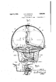
- J ig. 1 is a front view of the machine resting uponra drain board attached to a sink, 2 and showing a hose connection between the standpipe of themachine and an ordinary faucetl; Y
- Fig.l 2 is an end view of the machine showin t e machine placed directly in a sin (s ownin vertical section) with the standpipe in draining position;
- Fig. 3 is an enlarged end elevation of the machine with the movable top section in closed position, sectioned on the line 3-3 o 3 Fig. 5;
- Fig. 4 is an enlarged front elevation of the4 machine, sectioned on line 4--4 of Fig. 3;
- Figr is a plan tioned on the line 5-5 of Fig. 3, showing the strainer broken away, and including a phantom view of the tank;
- Fig. 6 is an enlarged fragmentary horizontal section on the line 6-6 of Fig. 3;
- Fig. 7 is an. enlarged vertical section on the sum and pump unit taken 'on the line 7-7 of ig. 4, showing the distributor mountini ⁇ in axial section;
- ig. 8 is a section of the sump and pump unit taken on the line 8-8 of Fig. 3;
- Fig. 9 is a section of the sump and pump unit on the lines 9-9 lof Figs. 4, 5 and 8, showing the pump involute drain channel.
- the dish washing machine illustrated is ofthetype in which soapy water or other washing medium i's drawn from a sump or view of the machine sec- No. 92,387. Renewed January 3, 1982. v
- the water which has passed over the dishes drains back into the sump so that lt-may be used repeatedly.
- the casing of the machine is made entirely of sheet metal. It may consist of only four parts, each of which may be drawn or otherwise formed from a single piece of sheet metal. These parts include a supporting shell 10, a shallow tank 11, a fixed cover section 12 and a movable cover section 13.
- the supporting shell 10 contains the motor, pump, and sump, and may be made of small area owing to the fact that the pump and sump are combined in a single unit, as hereinafter explained.
- the small area of the sup. porting section facilitates placing the machine on a sink, as shown in Fig. 2, or on a Wash tub, without interference with the faucets.
- the shallow tank 11 is secured to and rests on the upper edge of the ⁇ supporting an opening 14 leading to the sump 1.
- the fixed section 12 has a cylindrically curved top 15 and flat ends 16 consisting of sectors of a. circle only slightly greater than quadrants and low proectons 17 extending toward the front of the tank.
- the end walls may be provided with external. strengthening'lpieces 18.
- the movable section has also a cylindrically curved top 19 and fiat ends 20 consisting of sectors of a circle slightly greater thanquadrants. The movable section is pivoted to the fixed section at 21 so that it may be turned within the fixed section.
- a clearance is provided between the ends and tops ofthe fixed and movable sections 12,
- the sump 1 and pump 2 are combined in a single unit 30 (which may most desirably consist of a single castingl as shown) forming a box-like reservoir which constitutes the sump' 1 and the involute casing31 of the pump 2 which is of the centrifugal type.
- the unit 30 has an external flange 32 atIit-s upper edge, which is secured to the bottom of the tank 11 about the edge of the opening 14.
- a removable strainer 33 may be seated on the inner part ofthe flange 32.
- One wall 34 of the pump casing 31 forms part of one of the side walls of the sump and contains an opening 35y for the passage of liquid from the sump to the pump casing.
- the discharge neck or conduit 36 of the pump casing rises within the sump 1 and extends into the tank 11 through the opening 14.
- the impeller 37 of the pump is driven by an electric motor 38 mounted on a strip 39 extending across the inturned lower edge 40 ofthe supporting shell 10.
- the impeller shaft' 41 passes through two stuffing boxes 42 in the outer wall 43 of the pump casing 31.
- a drain passage 44 in the wall 43 diverts any liquid l which may leak through the inner stuiing box and prevents it from entering a bearing 45 in which the shaft 41 is supported.
- the unit 30 has at one of its lower edges a hollow cylindrical extension or sleeve 46 which communicates with the sump through. an opening 47.
- a drain channel 48 formed in the bottom of the unit 30 extends from the lowest point of the pump casing 31 to the sleeve 46 opening into the sleeve )11st below the opening 47.
- a combined filling, overflow, and drain pipe 50 extends through the sleeve 46 and is turnable therein.
- the inner end of the pipe 50 is closed by a plug .52 while the outer end of the pipe extends through a hole 53 in the shell 10 and is turned nearly at right angles to the rest of the pipe to form an open standtion which holds the pipe 50 and its standpipe 54 in an position into which they may be turned.
- urning of the pipe 50 is positively limited by the engagement of sto s 57, 58 on a collar 59 with a strip 60 whic extends across the bottom of the shell 10.
- Thel stops are placed so that the pipe'50 may be ,turned between a position in which its standpipe 54 is turned vertically upward (as shown in Figs.
- the portion of the pipe 50 within the sleeve 46 contains a lateral port 62 which registers with the drain opening 47 of the sump inall positions of the pipe 50 and with the drain channel 48 from the pump casing only when lthe standpipe is turned down (see Figs. 3. 4, 5, and Figs. 7 and 9 which show the position of the port 62 when the standpipe is turned down to the position indicated by dot. and dash lines in Fig. 3).
- the sump land tank 11 may be filled through the pipe 50, for example, by means of a ru'bber hose, vas shown in Fig. 1.
- the machine may be filled by raising the door 13' ⁇ and'pouring water directly into the tank 11.
- the standpipe 54 acts as an overflow pipe determining the level of the liquid in the tank 11 and preventing the liq-v uid from rising high enough to interfere with the rotary distributor 3, hereinafter described.
- the standpipe 54 is maintained in upright position during the operation of the machine, thus preventing the escape of water fromthe sump, while at the same time the wall of the pipe -50 prevents any water from passing out of the pump casing through the drain channel 48.
- both the'sump and the pump casing are completely dra-ined through the pipe 50 and the standpipe. This not only prevents sta ant water from collecting in the pump caslng, but is of particular advantage in a machine intended for household use, since the soapy water used in washing the dishes may be quickly and completely withdrawn from pipe 54 at the left-hand end of the machine,
- the rotary distributor 3 is of the type cuspipe 5,4. Lengthwise movementofthe pipe 50 itomarily known as a rotary wash arm. It
- the springpressed collar 56A serves also to create fric has a hub 70 and radial arms 71 provided with upwardly directed nozzles 72 ⁇ some of which are inclined so that the distributor is rotated by reaction.
- the hub 70 is mounted on a hollow pin 73 which fits within and rests on the upper end of the discharge conduit 36 of the pump casing.
- the pin is provided with lateral outlet openings 74 whose combined area is .greater than that of the cross-section ofI the discharge neck 36 so that the liquid which is forced through the pin does not tend to raise it from the discharge neck.
- the pin 73 may be made freely removable from the discharge nec-k without any attachment thereto. This facilitates removing the pin for cleaning.
- the upper end of the hub 7 0 of the' distributor is open and provided with an internal lflange 75 which supports the distributor by resting on an external flange 76 near the upper end of the pin 73.
- the lower portion 77 of the hub has a running fit over a rib- 78 on the pin.
- the opening at the upper end of the hub 70 is of such size that, when any fluid is passing through it, fluid pressure within the distributor does not tend to blow ofi' the pin. Consequently, the distributor may be made freely removable from the pin without any attachment whatever, so that it need merely be lifted off for cleaning.
- fluid When fluid is forced into the distributor, it raises the distributor slightly until a thin film of water flows out between the flanges and 76. The distributor then floats on this film of water so that it rotates easily and wear on the flanges 75 and 76 is avoided.
- a casing enclosing a washing chamber and comprising a fixed section having a curved top and flat approximately quadrant-shaped end walls, a movable casing pivoted to the fixed casing and having a curved top and approximately quadrant-shaped end walls spaced inwardly from the fixed end walls and overlapping the edges of the same when the movable section is in closed position, inward projections on the fixed end walls, and outward projections on the movable end walls forming a tortuous path between the overlapping portions of the end walls adapted to permit the escape of steam and obstruct the passage of Water.
- a washin machine having a casing comprising a s allow tank, a fixed section having a curved top and approximately quadrant-shaped end walls and having an inwardly projecting flange along the front edge of its top and its end walls, and a movable sectlon pivoted to the fixed section and having a cylindrical top and approximately a curved top and end walls comprising quadrants rising from the rear half of the side edges of the tank and low projections rising from the front portion of the side edges of the tank, a movablesection having a curved top and approximately quadrant-shaped end walls whose lower edges fit withinthe forward projections of the fixed end walls, and baflles projecting inwardly from said projections below the lower edge of the end walls of the movable section.
- a casing comprising a shallow tank, a fixed section having a curved top and flat end walls forming more than one-quarter and less than one-half of a hollow cylinder, a movable section pivoted to turn within the fixed section and having a curved top and flat end walls constituting more than one-quarter and less than one-half of a hollow cylinder so that the fixed and movable sections overlap when the movable casing is in closed position, and means for preventing the escape of liquid between the overlapping portions of the curved tops of the fixed and movable sections, comprising a ridge formed on each curved top and projecting towards the other curved top, at least one of said ridges being spaced from the edge of the top from which it projects.
Description
April 12, 1932. E. R. zApEMAcH f WASHING MACHINE 4 Sheets-Sheet 1 original Filled M arch 5, 192el Mm WN \A.QA :W QNI. \N m )QN xww l ATTO NEY April 1/25 1932. E, R. zADEMAcH wA'sHINeMAcHINE 4 Sheets-Sheet 2 original Filed. March 5, 19'26 INVENTOR A11 RNEY pril 12, '1932, E. R. zADEMAcH WASHING MACHINE 4 Sheets-Sheet 5 `Original Filed March 1926 INVENTOR @dg/W75@ ATTORNEY April l2, 1932. E. R. ZADEMACH WASHING MACHINE 4 Sheets-Sheet 4 Original Filed March 5, 1926 :mmm
.INVENTOR Patented Apr. 12, 1932 UNITED STATES-PATENT .OFFICE ERICH B. ZADEM'ACH, 0F ELIZABETH, NEW JERSEY, ASSIGNOR, BY .IiESNE ASSIGN- MENTS, TO HOBART HANFACTUBING COMPANY,
OF OHIO application ale-a umn s, 1m, smal This invention relates to washing machines and aims particularly to provide a simple, inexpensive, compact, and effective dish washing machine for household use.
[6 Objects of the invention are to provide, in
such a machine, a convenient and inexpensive casing, a compactV pump and sump unit, a combined filling, drain, and overfiow pipe which automatically drains the pump casing l as well as the sump, and a distributor which is freely removable to facilitate,v cleaning.
Other objects and advantages of the invention are hereinafter set forth in connection with a detailed description ofthe mach'ne embodying the various features of the invention which are shown in the accompanying drawings inl which J ig. 1 is a front view of the machine resting uponra drain board attached to a sink, 2 and showing a hose connection between the standpipe of themachine and an ordinary faucetl; Y
Fig. 3 is an enlarged end elevation of the machine with the movable top section in closed position, sectioned on the line 3-3 o 3 Fig. 5;
Fig. 4 is an enlarged front elevation of the4 machine, sectioned on line 4--4 of Fig. 3;
Figr is a plan tioned on the line 5-5 of Fig. 3, showing the strainer broken away, and including a phantom view of the tank;
Fig. 6 is an enlarged fragmentary horizontal section on the line 6-6 of Fig. 3;
Fig. 7 is an. enlarged vertical section on the sum and pump unit taken 'on the line 7-7 of ig. 4, showing the distributor mountini` in axial section;
ig. 8 is a section of the sump and pump unit taken on the line 8-8 of Fig. 3; and
Fig. 9 is a section of the sump and pump unit on the lines 9-9 lof Figs. 4, 5 and 8, showing the pump involute drain channel.
The dish washing machine illustrated is ofthetype in which soapy water or other washing medium i's drawn from a sump or view of the machine sec- No. 92,387. Renewed January 3, 1982. v
the dishes. The water which has passed over the dishes drains back into the sump so that lt-may be used repeatedly.
The casing of the machine is made entirely of sheet metal. It may consist of only four parts, each of which may be drawn or otherwise formed from a single piece of sheet metal. These parts include a supporting shell 10, a shallow tank 11, a fixed cover section 12 and a movable cover section 13. The supporting shell 10 contains the motor, pump, and sump, and may be made of small area owing to the fact that the pump and sump are combined in a single unit, as hereinafter explained. The small area of the sup. porting section facilitates placing the machine on a sink, as shown in Fig. 2, or on a Wash tub, without interference with the faucets. The shallow tank 11 is secured to and rests on the upper edge of the `supporting an opening 14 leading to the sump 1. The
OF TROY, OHIO, A CORPORATION l fixed cover section 12 and the vmovable cover section erdoor 13 enclose a washing chamf ber above the tank 11. -The fixed section 12 has a cylindrically curved top 15 and flat ends 16 consisting of sectors of a. circle only slightly greater than quadrants and low proectons 17 extending toward the front of the tank. The end walls may be provided with external. strengthening'lpieces 18. The movable section has also a cylindrically curved top 19 and fiat ends 20 consisting of sectors of a circle slightly greater thanquadrants. The movable section is pivoted to the fixed section at 21 so that it may be turned within the fixed section. Because of the fact that the end walls of the fixedand movable sections are of approximate quadrant shape this-exposesone-half of the top and ends the tank 3, thus facilitating the placing of a rack 22 of dishes 23 or other articles on rails 24 provided for its support and the removal of therack therefrom.
A clearance is provided between the ends and tops ofthe fixed and movable sections 12,
13 to permit the escape of steam during the washing` operation, thus avoiding danger of scalding the user by a sudden escape of steam when the door is opened. Leakage of water between the fixed and movable sections is prevented by an inturned flange 25 at the front edge of the top and' sides of the fixed section and outwardly projecting ribs 26'near the back edge of the top and sides of the movable section. Leakage under the lower edge of the `movable section isprevented by an inturned flange 27 at the front edge of the tank 11 and by bailles 28 projecting inwardly from the forward projections 17 of the end walls of the ixed section just under-'the lower edge of the end walls of the movable section.
The sump 1 and pump 2 are combined in a single unit 30 (which may most desirably consist of a single castingl as shown) forming a box-like reservoir which constitutes the sump' 1 and the involute casing31 of the pump 2 which is of the centrifugal type. The unit 30 has an external flange 32 atIit-s upper edge, which is secured to the bottom of the tank 11 about the edge of the opening 14. A removable strainer 33 may be seated on the inner part ofthe flange 32. One wall 34 of the pump casing 31 forms part of one of the side walls of the sump and contains an opening 35y for the passage of liquid from the sump to the pump casing. The discharge neck or conduit 36 of the pump casing rises within the sump 1 and extends into the tank 11 through the opening 14. The impeller 37 of the pump is driven by an electric motor 38 mounted on a strip 39 extending across the inturned lower edge 40 ofthe supporting shell 10. The impeller shaft' 41 passes through two stuffing boxes 42 in the outer wall 43 of the pump casing 31. A drain passage 44 in the wall 43 diverts any liquid l which may leak through the inner stuiing box and prevents it from entering a bearing 45 in which the shaft 41 is supported.
To provide for draining both the sump and.
the pump casing,l the unit 30 has at one of its lower edges a hollow cylindrical extension or sleeve 46 which communicates with the sump through. an opening 47.- A drain channel 48 formed in the bottom of the unit 30 extends from the lowest point of the pump casing 31 to the sleeve 46 opening into the sleeve )11st below the opening 47.
A combined filling, overflow, and drain pipe 50 extends through the sleeve 46 and is turnable therein. The inner end of the pipe 50 is closed by a plug .52 while the outer end of the pipe extends through a hole 53 in the shell 10 and is turned nearly at right angles to the rest of the pipe to form an open standtion which holds the pipe 50 and its standpipe 54 in an position into which they may be turned. urning of the pipe 50 is positively limited by the engagement of sto s 57, 58 on a collar 59 with a strip 60 whic extends across the bottom of the shell 10. Thel stops are placed so that the pipe'50 may be ,turned between a position in which its standpipe 54 is turned vertically upward (as shown in Figs. 1 and 4 and in dotted lines in Fig. 3), and a position in'which the standpipe 54 is inclined rearwardly and slightly downward (as shown in Fig. 2 and in dot and dash lines in Fig.l3 Y The portion of the pipe 50 within the sleeve 46 contains a lateral port 62 which registers with the drain opening 47 of the sump inall positions of the pipe 50 and with the drain channel 48 from the pump casing only when lthe standpipe is turned down (see Figs. 3. 4, 5, and Figs. 7 and 9 which show the position of the port 62 when the standpipe is turned down to the position indicated by dot. and dash lines in Fig. 3). Y
When the standpipe 54 is turned upward, the sump land tank 11 may be filled through the pipe 50, for example, by means of a ru'bber hose, vas shown in Fig. 1. Alternatively, the machine may be filled by raising the door 13'\and'pouring water directly into the tank 11. In either case the standpipe 54 acts as an overflow pipe determining the level of the liquid in the tank 11 and preventing the liq-v uid from rising high enough to interfere with the rotary distributor 3, hereinafter described. The standpipe 54 is maintained in upright position during the operation of the machine, thus preventing the escape of water fromthe sump, while at the same time the wall of the pipe -50 prevents any water from passing out of the pump casing through the drain channel 48.
When the standpipe 54 is inclined down- Wardly, both the'sump and the pump casing are completely dra-ined through the pipe 50 and the standpipe. This not only prevents sta ant water from collecting in the pump caslng, but is of particular advantage in a machine intended for household use, since the soapy water used in washing the dishes may be quickly and completely withdrawn from pipe 54 at the left-hand end of the machine,
as shown in Fig. 2.
The rotary distributor 3 is of the type cuspipe 5,4. Lengthwise movementofthe pipe 50 itomarily known as a rotary wash arm. It
is-prevented by a fixed collar 55 anda springpressed collar 56 engaging oppositeends of the sleeve 46 (see Fig. 4). The springpressed collar 56A serves also to create fric has a hub 70 and radial arms 71 provided with upwardly directed nozzles 72` some of which are inclined so that the distributor is rotated by reaction. The hub 70 is mounted on a hollow pin 73 which fits within and rests on the upper end of the discharge conduit 36 of the pump casing. The pin is provided with lateral outlet openings 74 whose combined area is .greater than that of the cross-section ofI the discharge neck 36 so that the liquid which is forced through the pin does not tend to raise it from the discharge neck. In consequence the pin 73 may be made freely removable from the discharge nec-k without any attachment thereto. This facilitates removing the pin for cleaning.
The upper end of the hub 7 0 of the' distributor is open and provided with an internal lflange 75 which supports the distributor by resting on an external flange 76 near the upper end of the pin 73. The lower portion 77 of the hub has a running fit over a rib- 78 on the pin.
The opening at the upper end of the hub 70 is of such size that, when any fluid is passing through it, fluid pressure within the distributor does not tend to blow ofi' the pin. Consequently, the distributor may be made freely removable from the pin without any attachment whatever, so that it need merely be lifted off for cleaning. When fluid is forced into the distributor, it raises the distributor slightly until a thin film of water flows out between the flanges and 76. The distributor then floats on this film of water so that it rotates easily and wear on the flanges 75 and 76 is avoided.
The operation of the machine will, it is believed, be readily apparent from the above description. In the use of the machine it is desirable, after insertingr -a rack of dishes throughthe door 13, to fill the machine with hot soapy water and operate it for a sufficient time to cleanse thedishes, and then to drain off this Water, refill the machine with clean hot water, and operate it again for a few moments to rinse the dishes.
Claims to certain important features of the machine which has been described have been divided out of this application under requirement of the Patent Oflice and form the subject-matter of my divisional applications, Serial Nos. 205,857, filed July 8, 1927and 205,858,1i1ed July s, 1927.
What isclaimed-is:
1. In a washing machine, a casing enclosing a washing chamber and comprising a fixed section having a curved top and flat approximately quadrant-shaped end walls, a movable casing pivoted to the fixed casing and having a curved top and approximately quadrant-shaped end walls spaced inwardly from the fixed end walls and overlapping the edges of the same when the movable section is in closed position, inward projections on the fixed end walls, and outward projections on the movable end walls forming a tortuous path between the overlapping portions of the end walls adapted to permit the escape of steam and obstruct the passage of Water.
2. A washin machine having a casing comprising a s allow tank, a fixed section having a curved top and approximately quadrant-shaped end walls and having an inwardly projecting flange along the front edge of its top and its end walls, and a movable sectlon pivoted to the fixed section and having a cylindrical top and approximately a curved top and end walls comprising quadrants rising from the rear half of the side edges of the tank and low projections rising from the front portion of the side edges of the tank, a movablesection having a curved top and approximately quadrant-shaped end walls whose lower edges fit withinthe forward projections of the fixed end walls, and baflles projecting inwardly from said projections below the lower edge of the end walls of the movable section.
4. In a washing machine, a casing `comprising a shallow tank, a fixed section having a curved top and flat end walls forming more than one-quarter and less than one-half of a hollow cylinder, a movable section pivoted to turn within the fixed section and having a curved top and flat end walls constituting more than one-quarter and less than one-half of a hollow cylinder so that the fixed and movable sections overlap when the movable casing is in closed position, and means for preventing the escape of liquid between the overlapping portions of the curved tops of the fixed and movable sections, comprising a ridge formed on each curved top and projecting towards the other curved top, at least one of said ridges being spaced from the edge of the top from which it projects.A
In testimony whereof I have hereunto set my hand.
ERICH R. ZADEMACH.
Priority Applications (3)
| Application Number | Priority Date | Filing Date | Title |
|---|---|---|---|
| US92387A US1853528A (en) | 1926-03-05 | 1926-03-05 | Washing machine |
| US20585727 US1853529A (en) | 1926-03-05 | 1927-07-08 | Washing machine |
| US20585827 US1878568A (en) | 1926-03-05 | 1927-07-08 | Washing machine |
Applications Claiming Priority (1)
| Application Number | Priority Date | Filing Date | Title |
|---|---|---|---|
| US92387A US1853528A (en) | 1926-03-05 | 1926-03-05 | Washing machine |
Publications (1)
| Publication Number | Publication Date |
|---|---|
| US1853528A true US1853528A (en) | 1932-04-12 |
Family
ID=22232958
Family Applications (1)
| Application Number | Title | Priority Date | Filing Date |
|---|---|---|---|
| US92387A Expired - Lifetime US1853528A (en) | 1926-03-05 | 1926-03-05 | Washing machine |
Country Status (1)
| Country | Link |
|---|---|
| US (1) | US1853528A (en) |
Cited By (8)
| Publication number | Priority date | Publication date | Assignee | Title |
|---|---|---|---|---|
| DE1174461B (en) * | 1960-07-20 | 1964-07-23 | Siemens Elektrogeraete Gmbh | Dishwasher |
| DE1182785B (en) * | 1962-05-23 | 1964-12-03 | Linde Eismasch Ag | Dishwasher, especially for dishes |
| US5518014A (en) * | 1995-02-21 | 1996-05-21 | Mceachen; Peter C. | Portable countertop dishwasher |
| US5745946A (en) * | 1994-07-15 | 1998-05-05 | Ontrak Systems, Inc. | Substrate processing system |
| US6612732B2 (en) * | 2001-10-19 | 2003-09-02 | Fluid Management, Inc. | Paint mixer |
| US20060054194A1 (en) * | 2004-09-14 | 2006-03-16 | Lg Electronics Inc. | Dishwasher |
| EP2468169A1 (en) * | 2010-12-21 | 2012-06-27 | Electrolux Home Products Corporation N.V. | Table top dishwasher |
| US20130334940A1 (en) * | 2010-08-06 | 2013-12-19 | Electrolux Home Products Corporation N.V. | Table top dishwasher |
-
1926
- 1926-03-05 US US92387A patent/US1853528A/en not_active Expired - Lifetime
Cited By (13)
| Publication number | Priority date | Publication date | Assignee | Title |
|---|---|---|---|---|
| DE1174461B (en) * | 1960-07-20 | 1964-07-23 | Siemens Elektrogeraete Gmbh | Dishwasher |
| DE1182785B (en) * | 1962-05-23 | 1964-12-03 | Linde Eismasch Ag | Dishwasher, especially for dishes |
| US5745946A (en) * | 1994-07-15 | 1998-05-05 | Ontrak Systems, Inc. | Substrate processing system |
| US5518014A (en) * | 1995-02-21 | 1996-05-21 | Mceachen; Peter C. | Portable countertop dishwasher |
| US6612732B2 (en) * | 2001-10-19 | 2003-09-02 | Fluid Management, Inc. | Paint mixer |
| US7614409B2 (en) * | 2004-09-14 | 2009-11-10 | Lg Electronics Inc. | Dishwasher |
| US20060054194A1 (en) * | 2004-09-14 | 2006-03-16 | Lg Electronics Inc. | Dishwasher |
| US20130334940A1 (en) * | 2010-08-06 | 2013-12-19 | Electrolux Home Products Corporation N.V. | Table top dishwasher |
| US9138124B2 (en) * | 2010-08-06 | 2015-09-22 | Electrolux Home Products Corporation N.V. | Table top dishwasher |
| KR101764460B1 (en) | 2010-08-06 | 2017-08-02 | 일렉트로룩스 홈 프로덕츠 코오포레이션 엔.브이. | Table top dishwasher |
| EP2468169A1 (en) * | 2010-12-21 | 2012-06-27 | Electrolux Home Products Corporation N.V. | Table top dishwasher |
| WO2012084998A1 (en) * | 2010-12-21 | 2012-06-28 | Electrolux Home Products Corporation N.V. | Table top dishwasher |
| US9022491B2 (en) | 2010-12-21 | 2015-05-05 | Electrolux Home Products Corporation N.V. | Table top dishwasher |
Similar Documents
| Publication | Publication Date | Title |
|---|---|---|
| US1853529A (en) | Washing machine | |
| US2157112A (en) | Machine for cleansing and treating | |
| US1853528A (en) | Washing machine | |
| US3060947A (en) | Dishwashing machine | |
| US3108607A (en) | Dish washing machine pump and drain | |
| US1946181A (en) | Dishwashing machine | |
| US2279619A (en) | Dish washing machine | |
| US2076688A (en) | Washing apparatus | |
| US1485796A (en) | Washing machine | |
| US1884180A (en) | Dish washing machine | |
| US1671557A (en) | Dishwashing machine | |
| US2143165A (en) | Dishwasher | |
| US1737794A (en) | Dishwashing machine | |
| US1624461A (en) | Dishwashing machine | |
| US1628818A (en) | Washing machine | |
| US1529770A (en) | Dishwashing machine | |
| US2078670A (en) | Dishwashing machine | |
| US2284026A (en) | Dishwasher | |
| US1976902A (en) | Dishwashing machine | |
| US2416616A (en) | Combination clothes and dish washing machine | |
| US1928683A (en) | Dishwashing machine | |
| US1963520A (en) | Washing machine | |
| US1955299A (en) | Dishwashing machine | |
| US1406599A (en) | Dish-washing machine | |
| US1951273A (en) | Dishwashing machine |