US1854080A - Lock arrangement for safe doors, etc. - Google Patents
Lock arrangement for safe doors, etc. Download PDFInfo
- Publication number
- US1854080A US1854080A US468945A US46894530A US1854080A US 1854080 A US1854080 A US 1854080A US 468945 A US468945 A US 468945A US 46894530 A US46894530 A US 46894530A US 1854080 A US1854080 A US 1854080A
- Authority
- US
- United States
- Prior art keywords
- tumblers
- key
- barrel
- lock
- carrier
- Prior art date
- Legal status (The legal status is an assumption and is not a legal conclusion. Google has not performed a legal analysis and makes no representation as to the accuracy of the status listed.)
- Expired - Lifetime
Links
- 230000006835 compression Effects 0.000 description 5
- 238000007906 compression Methods 0.000 description 5
- 238000010276 construction Methods 0.000 description 2
- MXBCYQUALCBQIJ-RYVPXURESA-N (8s,9s,10r,13s,14s,17r)-13-ethyl-17-ethynyl-11-methylidene-1,2,3,6,7,8,9,10,12,14,15,16-dodecahydrocyclopenta[a]phenanthren-17-ol;(8r,9s,13s,14s,17r)-17-ethynyl-13-methyl-7,8,9,11,12,14,15,16-octahydro-6h-cyclopenta[a]phenanthrene-3,17-diol Chemical compound OC1=CC=C2[C@H]3CC[C@](C)([C@](CC4)(O)C#C)[C@@H]4[C@@H]3CCC2=C1.C1CC[C@@H]2[C@H]3C(=C)C[C@](CC)([C@](CC4)(O)C#C)[C@@H]4[C@@H]3CCC2=C1 MXBCYQUALCBQIJ-RYVPXURESA-N 0.000 description 1
- CVRALZAYCYJELZ-UHFFFAOYSA-N O-(4-bromo-2,5-dichlorophenyl) O-methyl phenylphosphonothioate Chemical compound C=1C=CC=CC=1P(=S)(OC)OC1=CC(Cl)=C(Br)C=C1Cl CVRALZAYCYJELZ-UHFFFAOYSA-N 0.000 description 1
- 230000037431 insertion Effects 0.000 description 1
- 238000003780 insertion Methods 0.000 description 1
- 238000003032 molecular docking Methods 0.000 description 1
- 230000002093 peripheral effect Effects 0.000 description 1
- 238000009877 rendering Methods 0.000 description 1
Images
Classifications
-
- E—FIXED CONSTRUCTIONS
- E05—LOCKS; KEYS; WINDOW OR DOOR FITTINGS; SAFES
- E05B—LOCKS; ACCESSORIES THEREFOR; HANDCUFFS
- E05B27/00—Cylinder locks or other locks with tumbler pins or balls that are set by pushing the key in
- E05B27/0028—Other locks than cylinder locks with tumbler pins or balls
-
- Y—GENERAL TAGGING OF NEW TECHNOLOGICAL DEVELOPMENTS; GENERAL TAGGING OF CROSS-SECTIONAL TECHNOLOGIES SPANNING OVER SEVERAL SECTIONS OF THE IPC; TECHNICAL SUBJECTS COVERED BY FORMER USPC CROSS-REFERENCE ART COLLECTIONS [XRACs] AND DIGESTS
- Y10—TECHNICAL SUBJECTS COVERED BY FORMER USPC
- Y10T—TECHNICAL SUBJECTS COVERED BY FORMER US CLASSIFICATION
- Y10T70/00—Locks
- Y10T70/50—Special application
- Y10T70/5093—For closures
- Y10T70/5155—Door
- Y10T70/5199—Swinging door
- Y10T70/5246—Dead bolts
- Y10T70/5296—Single
- Y10T70/5319—Sliding
- Y10T70/5341—Key operable only
-
- Y—GENERAL TAGGING OF NEW TECHNOLOGICAL DEVELOPMENTS; GENERAL TAGGING OF CROSS-SECTIONAL TECHNOLOGIES SPANNING OVER SEVERAL SECTIONS OF THE IPC; TECHNICAL SUBJECTS COVERED BY FORMER USPC CROSS-REFERENCE ART COLLECTIONS [XRACs] AND DIGESTS
- Y10—TECHNICAL SUBJECTS COVERED BY FORMER USPC
- Y10T—TECHNICAL SUBJECTS COVERED BY FORMER US CLASSIFICATION
- Y10T70/00—Locks
- Y10T70/70—Operating mechanism
- Y10T70/7441—Key
- Y10T70/7446—Multiple keys
- Y10T70/7458—Interdependent
-
- Y—GENERAL TAGGING OF NEW TECHNOLOGICAL DEVELOPMENTS; GENERAL TAGGING OF CROSS-SECTIONAL TECHNOLOGIES SPANNING OVER SEVERAL SECTIONS OF THE IPC; TECHNICAL SUBJECTS COVERED BY FORMER USPC CROSS-REFERENCE ART COLLECTIONS [XRACs] AND DIGESTS
- Y10—TECHNICAL SUBJECTS COVERED BY FORMER USPC
- Y10T—TECHNICAL SUBJECTS COVERED BY FORMER US CLASSIFICATION
- Y10T70/00—Locks
- Y10T70/70—Operating mechanism
- Y10T70/7441—Key
- Y10T70/7486—Single key
- Y10T70/7508—Tumbler type
- Y10T70/752—Sliding tumblers
- Y10T70/7531—Transverse
-
- Y—GENERAL TAGGING OF NEW TECHNOLOGICAL DEVELOPMENTS; GENERAL TAGGING OF CROSS-SECTIONAL TECHNOLOGIES SPANNING OVER SEVERAL SECTIONS OF THE IPC; TECHNICAL SUBJECTS COVERED BY FORMER USPC CROSS-REFERENCE ART COLLECTIONS [XRACs] AND DIGESTS
- Y10—TECHNICAL SUBJECTS COVERED BY FORMER USPC
- Y10T—TECHNICAL SUBJECTS COVERED BY FORMER US CLASSIFICATION
- Y10T70/00—Locks
- Y10T70/70—Operating mechanism
- Y10T70/7441—Key
- Y10T70/7486—Single key
- Y10T70/7508—Tumbler type
- Y10T70/7559—Cylinder type
- Y10T70/7565—Plural tumbler sets
-
- Y—GENERAL TAGGING OF NEW TECHNOLOGICAL DEVELOPMENTS; GENERAL TAGGING OF CROSS-SECTIONAL TECHNOLOGIES SPANNING OVER SEVERAL SECTIONS OF THE IPC; TECHNICAL SUBJECTS COVERED BY FORMER USPC CROSS-REFERENCE ART COLLECTIONS [XRACs] AND DIGESTS
- Y10—TECHNICAL SUBJECTS COVERED BY FORMER USPC
- Y10T—TECHNICAL SUBJECTS COVERED BY FORMER US CLASSIFICATION
- Y10T70/00—Locks
- Y10T70/70—Operating mechanism
- Y10T70/7441—Key
- Y10T70/7486—Single key
- Y10T70/7508—Tumbler type
- Y10T70/7559—Cylinder type
- Y10T70/7588—Rotary plug
- Y10T70/7593—Sliding tumblers
-
- Y—GENERAL TAGGING OF NEW TECHNOLOGICAL DEVELOPMENTS; GENERAL TAGGING OF CROSS-SECTIONAL TECHNOLOGIES SPANNING OVER SEVERAL SECTIONS OF THE IPC; TECHNICAL SUBJECTS COVERED BY FORMER USPC CROSS-REFERENCE ART COLLECTIONS [XRACs] AND DIGESTS
- Y10—TECHNICAL SUBJECTS COVERED BY FORMER USPC
- Y10T—TECHNICAL SUBJECTS COVERED BY FORMER US CLASSIFICATION
- Y10T70/00—Locks
- Y10T70/70—Operating mechanism
- Y10T70/7441—Key
- Y10T70/7915—Tampering prevention or attack defeating
- Y10T70/7955—Keyhole guards
- Y10T70/7977—Key-controlled
Definitions
- This :invention relates .to locking .devices, and particularlysto devices which are especiallyradapted 'iforsassociation with safe doors. or -thelike
- the .general object of the invention is itoprovlidexa device .of "this vclass lwhich is simpleIconstruction ⁇ Landhighly eiiicient .in operation to tpl-:event Aopening vof .the ⁇ safe- ;do'or fandsaccess tothecontents of the safe 0I' other r closure fby zunautho-rized persons.
- /A ffur-ther Iobject .of fthe invention is to provide wa idevi'ee having constructional ⁇ features Which Will decrease or 'evensnbstan'tialfly eelimnatethe t'possibility of- :an intruder disabling ⁇ the .fprarts of'tlae .device to causesth'e esame to "cease functioni-n'g. -An important featureiolfthesdevice .in thisA connection; is1the iai-.rangement and construction ..o ⁇ the @pin ltumblersrfan'd their:associated. ⁇ springs.
- the device comprises .essentially a :lock rbodylattadhed'itoi'thelsafe doorfwhichslidably foal-'ries la lookin-'g .fbo'ltcarrier .and frotatably ycarries.afkeybarrel.
- The/bolt carrier 1 is. pro 'rvidedwithla set (5f-.spring actuated yturmblers'whi'ch lfunct-ion to lock it to theibody vm'fhilef'the?bodyzis:provided Wthztwo sets of rpintum''l ⁇ lers,:.one fsetr Yof which is.
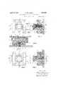
- Fig. 5 is a sectional vievvalong vline EF of Fig. 14:; Y
- Fig. 6 is a sectional vieW'alongG-.H of L55 ,Figa Y,
- ⁇ 'Ihedevioe comprises .avlock $15 body. composed ofinembers, 2 and 6 :Which-.are vattached tofthe ldoor 1by any suitable fastening vmeans, such as bolts runningithrongh the body members.
- fThef lock'bod'yv slid-ablycar- 0 .tailed intomember, asshown clearly in- Figs. Saandrf. :Carrier 3 is'provided'vvith a :suita- -ble setof recessesvvhich vare adapted to carry pin tumbler-s 4.' These.
- the lock body is provided with a set of apertures extending through the members thereof which carry slidable pin tumblers 8. These tumblers are adapted to actuate tumblers 4 carried by carrier 3 when the device is operated to unlock the same.
- Member 6 of the lock body is shaped at its front end to provide a protruding cylindrical portion upon which a key barrel 12 is rotatably mounted.
- the key barrel is provided with an inner peripheral iange having slots 14 therein through which screws 13 extend. These ⁇ screws are attached to member 6 and function not only to attach the key barrel to the lock body, but also as stops to limit the rotation of the key barrel. In the present instance, the barrel is adapted to be rotated through 90, as will appear more clearly hereinafter, but it is obvious that any desired angle may be used.
- the lock body is also provided with a set of recesses which carry pin tumblers 15 and which are disposed at right angles to the ⁇ ap ertures carrying tumblers 8, as shown clearly in Fig. 7.
- Pin tumblers 15 are shaped similar to tumblers 4, and are also actuated by coil springs disposed at the bottom of the recesses and surrounding the restricted inner portions of the tumblers.
- the key barrel is provided with a set of apertures extending through the central portion Jthereof and carrying pin tumblers 7. These tumblers have the greater part of their length of restricted diameter, while their inner ends are of substantially the same diameter as the recesses carrying tumblers 15.
- the apertures in the key barrel are shaped to conform with and accommodate pin tumblers 7, as will be clearly apparent from Figs. 2 and 5.
- pin tumblers 15 The purpose of pin tumblers 15 is to lock the key barrel in a certain position with respect to the lock body when the device is in locked condition. They are shown in this position in Fig. 2, and it is apparent from Fig. 3 that in such instance, access to tumblers 8 to unlock the device is prevented by the key barrel. In other words, it is necessary that the key barrel be rotated through 90 to the position shown in Fig. 4 to bring its apertures and tumblers 7 in alignment With the apertures and tumblers 8 in the lock body to unlock the device. Tumblers 7 are of varying lengths so that it requires a key having suitable prongs to move these tumblers and actuate tumblers 15 until theirouter ends lie in the plane of contact of the key barrel and the lock body.
- tumblers 15 will, of course, be moved from the recesses in the key barrel and the barrel may be rotated through the necessary angle to align its apertures and tumblers v7 with tumblers 8.
- This condition-of the various parts is shown in Fig. 5.
- the contacting surfaces of the tumblers 4 and 8 be brought into the plane of contact between carrier 3 and member 2.
- a different key will be required to force tumblers 8, and, therefore, tumblers 4, rearwardly until the desired unlocking positions of the parts are obtained.
- the necessary keys for the device are shown adjacent the devices of Figs. 2 and 5.
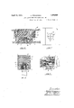
- Figs. 8 and 9 there is disclosed a modified form of the device in which pin tumblers 8 and 15 carried by the lock body may extend entirely through the apertures in the key barrel.
- the pin tumblers carried by the key barrel in the preferred embodiment, just described are omitted and .tumblers 8 and 15 are elongated and provided with extending restricted front portions.
- the apertures through the key barrel are restricted throughout their length while the recesses in the lock body are'shaped as shown clearly in the figures to conform with and accommodate the tumblers.
- the modified device is the same as the device of the preferred embodiment, and operates in a similar manner.
- the device of the preferred embodiment which utilizes tumblers. 7 ⁇ in the key barrel is, however, preferable to the modified device for several reasons. It will be noted in Figs. 3 and 5 that by virtue of the fact that a slight movement only of tumblers 8 is necessary to bring their front ends in the plane of contact between member 6 and barrel 12, the coil springs which actuate tumblers 4 are placed under slight compression when the device is in locking position. This is an important feature since such a device is normally in locked position during considerable periods of time. By having the springs under slight compression, they retain their resiliency and are very little affected, if at all, by long usage of the device. It will be understood, however, that the springs are placed under sufficient compression to properly operate'the device at all times.
- a lock for safe doors or the like coinprisinga lock body mountedon said door, a bolt carrier slidably carried by said body, a key barrel rotatably carried by said body to assume a plurality of positions, key operable means for locking said barrel in a certain position thereof, and key operable means for locking said carrier, said last mentioned means being accessible only When said barrel is in another of its positions.
- a lock for safe doors or the like comprising a lock body mounted on said door, a bolt carrier slidably carried by said body, a key barrel rotatably carried by said body to assume a plurality of positions, key operable means comprising pin tumblers carried by said body for locking said barrel in a certain position thereof, and key operable means comprising pin tumblers carried by said body and said carrier for locking said carrier, ⁇ said last mentioned means being accessible only when said barrel is in another of itspositions.
- a lock for safe doors or the like comprising a lock body mounted on'said door, a bolt carrier slidably'carried by said body, a
- a lock for safe doors or the like comprising a lock body mounted on said door and provided With a plurality of sets of pin tumblers, a bolt carrier slidably carried by said body and provided with a setof pin tumblers adapted to lock said carrier to said body and operable by one of said first-mentioned setsof tumblers to unlock said carrier, and a key barrel rotatably carried by said body and provided With a set of apertures into Which said first-mentioned sets of tumblers are adapted to extend to lock said barrel against rotation, said apertures being alignable With said one of said rst-mentioned sets of tumblers by insertion of a proper key therein to enable unlocking of said carrier.
- a lock for safe doors or the like comprising a lock body mounted on said door and provided With a plurality of sets of pin tumblers, a bolt carrier slidably carried by said body and provided With aset of pin tumblers adapted to lock said carrier vto said body and operable'by one of sai-d first-mentioned sets of tumblers to unlock said carrier, and a key Vbarrel rotatably carried by said body and ADOLPH TNNEssEN.
Description
Apri] 12, 1932. A, TNNESSEN 1,854,080
LOCK ARRANGEMENT FOR SAFE DOORS ETC Filed July 18, 1930 2 Sheets-Sheet l M m @mi/ April 12, 1932. A. TNNEssEN LOCK ARRANGEMENT FOR SAFE DOORS, ETC
2 Sheets-Sheet 2 Filed July 18,' 1930 Patented Apr. 12, 1932 Ynomen mNNEssEm 0F .samvnnena YnomivnY -LOCK .ARRNGEMENT IEOR'k SAFE DOORS, 'ETC'.
I Ajpplieatiomldfuly. 18,'1930,'.Seria1-No. 468,945,and in Norway March 1, 1930.
` This :invention relates .to locking .devices, and particularlysto devices which are especiallyradapted 'iforsassociation with safe doors. or -thelike The .general object of the invention is itoprovlidexa device .of "this vclass lwhich is simpleIconstruction` Landhighly eiiicient .in operation to tpl-:event Aopening vof .the `safe- ;do'or fandsaccess tothecontents of the safe 0I' other r closure fby zunautho-rized persons.
/A ffur-ther Iobject .of fthe invention is to provide wa idevi'ee having constructional `features Which Will decrease or 'evensnbstan'tialfly eelimnatethe t'possibility of- :an intruder disabling` the .fprarts of'tlae .device to causesth'e esame to "cease functioni-n'g. -An important featureiolfthesdevice .in thisA connection; is1the iai-.rangement and construction ..o `the @pin ltumblersrfan'd their:associated.` springs.
'The device comprises .essentially a :lock rbodylattadhed'itoi'thelsafe doorfwhichslidably foal-'ries la lookin-'g .fbo'ltcarrier .and frotatably ycarries.afkeybarrel. The/bolt carrier 1is. pro 'rvidedwithla set (5f-.spring actuated yturmblers'whi'ch lfunct-ion to lock it to theibody vm'fhilef'the?bodyzis:provided Wthztwo sets of rpintum''l` lers,:.one fsetr Yof which is. adapted to factuat'e fthe vLlo'olt .fcariierftumblers while :the other .set iis adapted :to lock the key '.'barrel iin-:a-fcertaineposition.fwithrespectLtofthetbody, Zth'erebyzpreventingg :access s to :the rst set `'of t1body'itumblersnntilsa iprop'erikeyv is inserted intherbarrel.
`?()ther f-objectsfo'fthe invention, as 'Welles fthe `estructuralA details o'if the .tdevice, will.. be
Reference amavy-.bef-hadto .theefollowing de- 'ftailed description :and the '..faccornpanying ndnavvingsfforz a-1f=ull=andfcomplete understand- `din-g.-of1thefinvention. Y
im In.then..drawings:
toffz'Eignl';
Fig 53 iseaffseotionall View lalong C-.D of Fig. l;
.Fig @.lfs'fa :.frontfzelevational .vieW: ,of the d 50 J`.devicen-With.:thexliey barrel-,in funlockedgposi- Vries arbolt carrier vvhich-ispreferab'ly clovel ianol'itsA carrier, a stop 111 isz-provided on; the carrier -vvh1chnalofuts,,againstfifnenalloer22;A
rtion and-allowing access to `the locking elements;
1 Fig. 5 is a sectional vievvalong vline EF of Fig. 14:; Y
Fig. 6 is a sectional vieW'alongG-.H of L55 ,Figa Y,
membernvvith whichy the device is adapted .to
be associated. `'Ihedevioe comprises .avlock $15 body. composed ofinembers, 2 and 6 :Which-.are vattached tofthe ldoor 1by any suitable fastening vmeans, such as bolts runningithrongh the body members. fThef lock'bod'yv slid-ablycar- 0 .tailed intomember, asshown clearly in- Figs. Saandrf. :Carrier 3 is'provided'vvith a :suita- -ble setof recessesvvhich vare adapted to carry pin tumbler-s 4.' These. tumblersare .preferalbly shaped asshown having their inn-er ends 5 lrestrictedfin :diameter andsurronndedby :coil springs Whose function isto normally press -the tumbler-'s :outward to t lock the carrier v'to thelockrbody As `'shown clearly inzlilgfs.` 3 and :5, Athe'restri'cted --en'd portions f of .these f tumbler-s .1 arezof such lengthzas f towextend at f'lea'st :half AWaythroughfthe coil' springs, ffr
arpurpose which Willbe/explained iherrein- I after; l l
fCarrer "3 has 'mounted on itsz'rear "Surface,
by means of'suitableffasteningscrews, or; the y like, a Abar 5. lThis `bar kis .-providedvvith. a frecessinto :which sa, detent 19; carried by s lthe locking :bolt V.10 f extends.. .The docking "'bolt :is f provided with :suitable .actuating .zfmeans of :any r conventionalftypel (not` shown) It "Wills, be apparent that; thelocking means come afprising 'detent9 and therecessainlbar ,"5 mainftainsthe bolt innrixefd relation Withfrespect f'to carrier 13,;andith'at `vvhenqi'fhe carrier'fis i lockedftor thec body by l:means of; itsfpinftumiblers, the loolteis likewiserenderedfimmovable. Inlforder `to limit the" movement .o "the bolt Y roo The lock body is provided with a set of apertures extending through the members thereof which carry slidable pin tumblers 8. These tumblers are adapted to actuate tumblers 4 carried by carrier 3 when the device is operated to unlock the same. Member 6 of the lock body is shaped at its front end to provide a protruding cylindrical portion upon which a key barrel 12 is rotatably mounted. The key barrel is provided with an inner peripheral iange having slots 14 therein through which screws 13 extend. These` screws are attached to member 6 and function not only to attach the key barrel to the lock body, but also as stops to limit the rotation of the key barrel. In the present instance, the barrel is adapted to be rotated through 90, as will appear more clearly hereinafter, but it is obvious that any desired angle may be used.
The lock body is also provided with a set of recesses which carry pin tumblers 15 and which are disposed at right angles to the` ap ertures carrying tumblers 8, as shown clearly in Fig. 7. Pin tumblers 15 are shaped similar to tumblers 4, and are also actuated by coil springs disposed at the bottom of the recesses and surrounding the restricted inner portions of the tumblers. The key barrel is provided with a set of apertures extending through the central portion Jthereof and carrying pin tumblers 7. These tumblers have the greater part of their length of restricted diameter, while their inner ends are of substantially the same diameter as the recesses carrying tumblers 15. The apertures in the key barrel are shaped to conform with and accommodate pin tumblers 7, as will be clearly apparent from Figs. 2 and 5.
The purpose of pin tumblers 15 is to lock the key barrel in a certain position with respect to the lock body when the device is in locked condition. They are shown in this position in Fig. 2, and it is apparent from Fig. 3 that in such instance, access to tumblers 8 to unlock the device is prevented by the key barrel. In other words, it is necessary that the key barrel be rotated through 90 to the position shown in Fig. 4 to bring its apertures and tumblers 7 in alignment With the apertures and tumblers 8 in the lock body to unlock the device. Tumblers 7 are of varying lengths so that it requires a key having suitable prongs to move these tumblers and actuate tumblers 15 until theirouter ends lie in the plane of contact of the key barrel and the lock body. At such time, tumblers 15 will, of course, be moved from the recesses in the key barrel and the barrel may be rotated through the necessary angle to align its apertures and tumblers v7 with tumblers 8. This condition-of the various parts is shown in Fig. 5. Obviously, in order to unlock the bolt carrier from the lock body andthereby release the bolt so that it may be actuated to unlock the door, it is necessary that the contacting surfaces of the tumblers 4 and 8 be brought into the plane of contact between carrier 3 and member 2. A different key will be required to force tumblers 8, and, therefore, tumblers 4, rearwardly until the desired unlocking positions of the parts are obtained. The necessary keys for the device are shown adjacent the devices of Figs. 2 and 5.
In Figs. 8 and 9, there is disclosed a modified form of the device in which pin tumblers 8 and 15 carried by the lock body may extend entirely through the apertures in the key barrel. In this instance, therefore, the pin tumblers carried by the key barrel in the preferred embodiment, just described, are omitted and . tumblers 8 and 15 are elongated and provided with extending restricted front portions. The apertures through the key barrel are restricted throughout their length while the recesses in the lock body are'shaped as shown clearly in the figures to conform with and accommodate the tumblers. Otherwise, the modified device is the same as the device of the preferred embodiment, and operates in a similar manner.
The device of the preferred embodiment which utilizes tumblers. 7` in the key barrel is, however, preferable to the modified device for several reasons. It will be noted in Figs. 3 and 5 that by virtue of the fact that a slight movement only of tumblers 8 is necessary to bring their front ends in the plane of contact between member 6 and barrel 12, the coil springs which actuate tumblers 4 are placed under slight compression when the device is in locking position. This is an important feature since such a device is normally in locked position during considerable periods of time. By having the springs under slight compression, they retain their resiliency and are very little affected, if at all, by long usage of the device. It will be understood, however, that the springs are placed under sufficient compression to properly operate'the device at all times. Contrasting this constructionwith that of Figs. 8 and 9, it will be noted that considerably more movement is necessary in the device of the latter figures tobring the front ends of tumblers 8 .into the contact plane between member 6 and key barrel 12. It will, therefore, be obvious that the springs of this device are placed under considerably greater compression. This same feature is, ofcourse, applicable to the springs which actuate tumblers 15 and 15 of the respective devices. Vhen the device is in unlocked position, these tumblers are, of course, maintained in their inwardly pressed position (see Fig. 6) and the springs remain under'compression'until the device is again locked.
Another feature, which is inherentin the preferred embodiment by virtue of the use of pin tumblers 7, is the fact that due to the varying lengths of these tumblers, a key having prongs of varying lengths is required to unlock the key barrel and enable rotation of the same. On the other hand, a key having prongs of equal length Will unlock the key barrel in t-he device of Figs. 8 and 9. Obviously, it would be easier for an intruder to make or obtain a key which Would unlock the barrel in the latter case.
As has already been stated,'an` important feature of the device of the Vinvention is the novel construction of the spring-actuated tumbler pins and their associated springs. It is often the practice of intruders Who encounter devicesY of this nature to flatten the coil springs by imparting a hard blow to the pin tumblers, thereby rendering the springs useless to perform their intended function. Since the restricted ends of the pin tumblers of the present device are of such length that.
they extend at least half Way through the coil springs, it Will be obvious that an in truder could at the most only partly flatten the springs. In other Words, he could not render the springs entirely inoperative and they Would perform-their intended function even though tampered with in the manner indicated.
@ther new and novel features of the device Will be apparent to persons skilled in the art. Obviously, changes in the structuraldetails of the device may be made Without departing from the spirit of the invention. It is, therefore, understood that the present disclosure is for the purpose of illustration only and.
that the invention is to be limited only by the scope of the appended claims.
I claim:
l. A lock for safe doors or the like, coinprisinga lock body mountedon said door, a bolt carrier slidably carried by said body, a key barrel rotatably carried by said body to assume a plurality of positions, key operable means for locking said barrel in a certain position thereof, and key operable means for locking said carrier, said last mentioned means being accessible only When said barrel is in another of its positions.
2. A lock for safe doors or the like, comprising a lock body mounted on said door, a bolt carrier slidably carried by said body, a key barrel rotatably carried by said body to assume a plurality of positions, key operable means comprising pin tumblers carried by said body for locking said barrel in a certain position thereof, and key operable means comprising pin tumblers carried by said body and said carrier for locking said carrier,` said last mentioned means being accessible only when said barrel is in another of itspositions.
3. A lock for safe doors or the like, comprising a lock body mounted on'said door, a bolt carrier slidably'carried by said body, a
to prevent access to said one set of pin tumblers until a proper key is inserted in said barrel.
4.-. A lock for safe doors or the like, comprising a lock body mounted on said door and provided With a plurality of sets of pin tumblers, a bolt carrier slidably carried by said body and provided with a setof pin tumblers adapted to lock said carrier to said body and operable by one of said first-mentioned setsof tumblers to unlock said carrier, and a key barrel rotatably carried by said body and provided With a set of apertures into Which said first-mentioned sets of tumblers are adapted to extend to lock said barrel against rotation, said apertures being alignable With said one of said rst-mentioned sets of tumblers by insertion of a proper key therein to enable unlocking of said carrier.
5. A lock for safe doors or the like, comprising a lock body mounted on said door and provided With a plurality of sets of pin tumblers, a bolt carrier slidably carried by said body and provided With aset of pin tumblers adapted to lock said carrier vto said body and operable'by one of sai-d first-mentioned sets of tumblers to unlock said carrier, and a key Vbarrel rotatably carried by said body and ADOLPH TNNEssEN.
Applications Claiming Priority (1)
| Application Number | Priority Date | Filing Date | Title |
|---|---|---|---|
| NO1854080X | 1930-03-01 |
Publications (1)
| Publication Number | Publication Date |
|---|---|
| US1854080A true US1854080A (en) | 1932-04-12 |
Family
ID=19910475
Family Applications (1)
| Application Number | Title | Priority Date | Filing Date |
|---|---|---|---|
| US468945A Expired - Lifetime US1854080A (en) | 1930-03-01 | 1930-07-18 | Lock arrangement for safe doors, etc. |
Country Status (1)
| Country | Link |
|---|---|
| US (1) | US1854080A (en) |
Cited By (6)
| Publication number | Priority date | Publication date | Assignee | Title |
|---|---|---|---|---|
| US2505494A (en) * | 1944-12-21 | 1950-04-25 | Yale & Towne Mfg Co | Key controlled tumbler lock |
| US2618957A (en) * | 1942-05-18 | 1952-11-25 | Arne Gilje | Cylinder type lock with plural tumbler sets |
| DE1201718B (en) * | 1960-12-08 | 1965-09-23 | Jean Albert Dreyfus | Lock with socket wrench |
| US4227387A (en) * | 1978-12-11 | 1980-10-14 | Chicago Lock Co. | Axial split-pin tumbler-type lock mechanism |
| US20070151313A1 (en) * | 2005-12-31 | 2007-07-05 | Hon Hai Precision Industry Co., Ltd. | Computer enclosure with locking apparatus |
| WO2021009037A1 (en) * | 2019-07-12 | 2021-01-21 | Sas Nexialiste Normand | Locking device |
-
1930
- 1930-07-18 US US468945A patent/US1854080A/en not_active Expired - Lifetime
Cited By (7)
| Publication number | Priority date | Publication date | Assignee | Title |
|---|---|---|---|---|
| US2618957A (en) * | 1942-05-18 | 1952-11-25 | Arne Gilje | Cylinder type lock with plural tumbler sets |
| US2505494A (en) * | 1944-12-21 | 1950-04-25 | Yale & Towne Mfg Co | Key controlled tumbler lock |
| DE1201718B (en) * | 1960-12-08 | 1965-09-23 | Jean Albert Dreyfus | Lock with socket wrench |
| US4227387A (en) * | 1978-12-11 | 1980-10-14 | Chicago Lock Co. | Axial split-pin tumbler-type lock mechanism |
| US20070151313A1 (en) * | 2005-12-31 | 2007-07-05 | Hon Hai Precision Industry Co., Ltd. | Computer enclosure with locking apparatus |
| US7428835B2 (en) * | 2005-12-31 | 2008-09-30 | Hon Hai Precision Industry Co., Ltd. | Computer enclosure with locking apparatus |
| WO2021009037A1 (en) * | 2019-07-12 | 2021-01-21 | Sas Nexialiste Normand | Locking device |
Similar Documents
| Publication | Publication Date | Title |
|---|---|---|
| US3234768A (en) | Key actuated mechanism with temporary ball tumbler | |
| US1854080A (en) | Lock arrangement for safe doors, etc. | |
| US3339384A (en) | Tumbler lock | |
| US924331A (en) | Lock. | |
| US2911814A (en) | Portable safe | |
| US2766605A (en) | Lock mechanism | |
| US1947443A (en) | Removable core lock | |
| US3473355A (en) | Two-key lock | |
| US1693481A (en) | Bar door lock | |
| US1622791A (en) | Door bolt | |
| US1510561A (en) | Lock | |
| US1799908A (en) | Combined lock and latch | |
| US181925A (en) | Improvement in lock and chain-fastening combined | |
| US1253169A (en) | Lock. | |
| US1025284A (en) | Lock attachment. | |
| US1226895A (en) | Keyless padlock. | |
| US631389A (en) | Padlock. | |
| US1082427A (en) | Key-fastener. | |
| US565622A (en) | Cylinder-lock | |
| US1814771A (en) | Lock | |
| US1243350A (en) | Safety device for door-locks. | |
| US1758395A (en) | Lock | |
| US435915A (en) | William m | |
| US164992A (en) | Improvement in key-hole guards | |
| US319014A (en) | Albbet p |