US1857076A - Hollow metal door and the like - Google Patents
Hollow metal door and the like Download PDFInfo
- Publication number
- US1857076A US1857076A US408531A US40853129A US1857076A US 1857076 A US1857076 A US 1857076A US 408531 A US408531 A US 408531A US 40853129 A US40853129 A US 40853129A US 1857076 A US1857076 A US 1857076A
- Authority
- US
- United States
- Prior art keywords
- molding
- stile
- rail
- moldings
- door
- Prior art date
- Legal status (The legal status is an assumption and is not a legal conclusion. Google has not performed a legal analysis and makes no representation as to the accuracy of the status listed.)
- Expired - Lifetime
Links
Images
Classifications
-
- E—FIXED CONSTRUCTIONS
- E06—DOORS, WINDOWS, SHUTTERS, OR ROLLER BLINDS IN GENERAL; LADDERS
- E06B—FIXED OR MOVABLE CLOSURES FOR OPENINGS IN BUILDINGS, VEHICLES, FENCES OR LIKE ENCLOSURES IN GENERAL, e.g. DOORS, WINDOWS, BLINDS, GATES
- E06B3/00—Window sashes, door leaves, or like elements for closing wall or like openings; Layout of fixed or moving closures, e.g. windows in wall or like openings; Features of rigidly-mounted outer frames relating to the mounting of wing frames
- E06B3/96—Corner joints or edge joints for windows, doors, or the like frames or wings
- E06B3/9604—Welded or soldered joints
-
- E—FIXED CONSTRUCTIONS
- E06—DOORS, WINDOWS, SHUTTERS, OR ROLLER BLINDS IN GENERAL; LADDERS
- E06B—FIXED OR MOVABLE CLOSURES FOR OPENINGS IN BUILDINGS, VEHICLES, FENCES OR LIKE ENCLOSURES IN GENERAL, e.g. DOORS, WINDOWS, BLINDS, GATES
- E06B3/00—Window sashes, door leaves, or like elements for closing wall or like openings; Layout of fixed or moving closures, e.g. windows in wall or like openings; Features of rigidly-mounted outer frames relating to the mounting of wing frames
- E06B3/70—Door leaves
- E06B3/72—Door leaves consisting of frame and panels, e.g. of raised panel type
- E06B3/725—Door leaves consisting of frame and panels, e.g. of raised panel type with separate hollow frames, e.g. foam-filled
- E06B3/726—Door leaves consisting of frame and panels, e.g. of raised panel type with separate hollow frames, e.g. foam-filled of metal
- E06B3/728—Door leaves consisting of frame and panels, e.g. of raised panel type with separate hollow frames, e.g. foam-filled of metal of sheet metal
Definitions
- Another. object of my invention is to pro.- tend theheight of the Stile. 'vide in articles of theabove type, stiffening means which may be spot-welded to reenforce the corners of the door or like construction and which will make the rails of the door self aligning during assembly.
- This invention relates particularly to hollow metal doors, but it may be applied to many other hollow metal frame construclegs 11, 12 of the U being tions, such as, window sashes and frames doortstile andthe base 13 of the U being the i I 1 outside verticaledge of the door.
- the inner edges of the stiles sides 11, 12 are reversely bent toward the inside of the stile, forming pockets: or troughs 14, which exy invention to provide panying drawings.
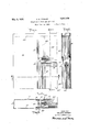
- Figure 1 is a from upper corner of a metal door constructed according to my invention. 1
- Figure 2 is a vertical sectional view through the door corner shown in Figure 1 the section being taken on the line IIII of I
- Figure 3 is a-horizontal sectional view of the door corner shown in: Figure l'the sectaken on the line III' III of Fig:
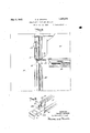
- - re 4 is an elevation viewpartlvin section of the door corner shown in Figural. This figure shows the p rtsjd ring n g
- the top rail 40 of the door is formed of
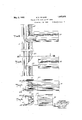
- Figure 8 is a top plan view of the construction shown in Figure 6.
- Figure 9 is a perspective o ing shown in Figure 6 and showing in detail the angle stiffener in position to receivethe of the assembly. 1
- Figure 5 is a front" elevation view 'ofa lower corner ioint between the stile molding and rail molding. 1
- Figure 6 is a front elevation view of the construction shown in Figure 5 but withthe rail molding pulled apart from "the stile Patented May 3, 1932 osoAR E. znnxnn, or GLENDALE, NEW YORK HOLLOW nnrmr. noon Ann rnn IKE,
- the door stile 10 is formed ofa rectangular sheet of metal folded over in U-shape,th( the sides of the a Secured to the stile is a molding formed of a rectangular sheet of metal which is symmetrically pressed so that a panel-receiving trough 21 is formed in its center while each of its sides 22, 23 is folded back from the trough forming the undulating molding suris described in connection with the acconr- .face
- theedgesof a panel 25 can be seatedin'the'troughs of'the moldings which surt elevation view'of an roundit. 7
- the edges of-the moldings sides 22, 23 are reversely bent outwardly to form pockets 24 complemental to the pockets 14 onthe stile.
- the molding and stile can be slid 'together with the reversely bent edge of the molding lying in pocket 14 of the stile while the reversely bent portion of the stile lies in the pocket 24 of the molding.
- Moldings 30, 31, which are identical in design and cross section to molding 20, are iep cured to thehorizontal rails of the door y f the M11 mold joints like the rolled joint just described. More specifically, the molding is secured to 1 the top rail and molding 31 may be secured.
- the stile molding 20 extends from just be-- low the top to just above the bottom of the stile.
- the rail molding is slightly shorter than the rail in order to allow overlapping of the stiles sides 11, -12 to presenter flat surface around the door.
- the side of each molding comprises three main portions, i. e. the joint portion a, design portion 6, and the trough g design: portions are mitered at their ends complementally to the stile molding-j
- the troughportion of the stile molding is cut away at each notched 0r mitered place but the trough portion of the rail molding extends to the end of the molding. 7
- the rail can be slid into cooperating relation with the stile, the projecting portion of the channel member 43 sliding between the sides 11, 12 of the stile and on top of the molding 20," while the plates of the rail slide uponthe jointportion a of the stile molding until they abut the sides 11, 12'.
- the angle members are of width equal to the distance between the opposed channels a, but are-only about onehalf the thicknessof a channel.
- One leg 51 of the angle is shorter than the other, the longer leg 53ha'ving asubstantially square aperture 52', located centrally thereof into which the corner of the molding can project as the angle is tilted (dotted line position Figure 1) during the insertion of its short leg up into the channels a of the stile.
- This aperture 52 is essential. If it were not present the angle could not be tilted enoughto allow it to be'inserted as described. After its insertionthe angle is .held with-its long leg perpendicular to the stile molding while its short leg is spot-welded in position.
- angle and channel member 43 serve to guide the rail during assembly and make the parts alignthemselves, thereby saving time required for assembly, and at the same timemaking a more rigid :joint than was possible heretofore.
- the moldings on the lower sides of the panel or panels are inverted relative to the top rail molding and hencethe mitering on the por tions of the stile molding cooperating with 1 a to rest upon'the'angle 50 and bridge the gap between the channels to carry the welding current and resist the pressurev applied during the welding operation. 7 p
- Hollow metal doors or the like comrislng a vertical member, a horizontal memer, moldings secured to said members and cooperating with each other, said moldings being 'cut to form a mitered' joint, and an angle member cooperating with said moldings, said anglemember" having'an aperture in one of its legs into which a corner of the moldingmay project, during assembling of the angle member andsaid molding.
- Hollow metal doors or the like comprising a vertical member, a horizontal member, moldings secured to said members and coopcrating with each'other, said moldings being cutto form a'mitered joint, and an angle member cooperating with said moldings, one leg of said angle member being longer'than the other and having an aperture therein into which a corner of the molding may'project during assembling of said molding with said anglei; V I
- said moldings having opposed parallelchannels and belng complementally mitered to form a miter joint, and an angle member adapted to have its legs slid into said channels and permanently secured therein, and a bar inserted in one of said moldings, whereby said rail may be joined to said stile molding Without burning the Welded parts.
Description
May 3, 1932. o. E. ZENKER HOLLOW METAL DOOR AND THE LIKE Filed Nov. 20, 1929 5 Sheets-Sheet 1 R w R N ME we NR A c S o y 1932- 0. E. ZENKER 1,857,076
HOLLQW METAL DOOR AND THE LIKE Filed Nov. 20,- 1929 s Sheets-Sheet 2 Tia:
INVENTOR OSCAR ElENKER 5y zls wizarizeya WWW May 3, 1932.
o. E. ZENKER HOLLOW METAL DOOR AND THE LIKE Filed Nov. 20, 1929 V 3 Sheets-Sheet 3 lNVENTOR OSCAR E.'ZENKER 8y kza wZ'ZOW/Zfyfi and the like.
It is an object of m improved means to assemble hollow metal doors and the like having slip-mitered joints between the moldings of the stiles and rails.
Another. object of my invention is to pro.- tend theheight of the Stile. 'vide in articles of theabove type, stiffening means which may be spot-welded to reenforce the corners of the door or like construction and which will make the rails of the door self aligning during assembly.
Other objects will appear as my invention ure 1.
This invention relates particularly to hollow metal doors, but it may be applied to many other hollow metal frame construclegs 11, 12 of the U being tions, such as, window sashes and frames doortstile andthe base 13 of the U being the i I 1 outside verticaledge of the door. In order that a molding may be secured to the stile, the inner edges of the stiles sides 11, 12 are reversely bent toward the inside of the stile, forming pockets: or troughs 14, which exy invention to provide panying drawings.
In the drawings: Figure 1 is a from upper corner ofa metal door constructed according to my invention. 1
Figure 2 is a vertical sectional view through the door corner shown in Figure 1 the section being taken on the line IIII of I Figure 3 is a-horizontal sectional view of the door corner shown in: Figure l'the sectaken on the line III' III of Fig:
- re 4 is an elevation viewpartlvin section of the door corner shown in Figural. This figure shows the p rtsjd ring n g The top rail 40 of the door is formed of,
' two parallel plates 41, 42 (Figure 2) joined 8 at their upper edges to the sides of a channel member 43 which runs the length of the plates and extends bevond them between the sides 11,}12 of the stile to an extent almost equal to the width ofsthe sides 11, 12. The 1 lower edges of theplates are reversely bent dl' kt t l'k th Figure 7 1s a top plan view of the construcgz g ig form Poe e S or roughs 1 6 tion shown in Figure 5; v 1
Figure 8 is a top plan view of the construction shown in Figure 6. i. v Figure 9 is a perspective o ing shown in Figure 6 and showing in detail the angle stiffener in position to receivethe of the assembly. 1
Figure 5 is a front" elevation view 'ofa lower corner ioint between the stile molding and rail molding. 1
Figure 6 is a front elevation view of the construction shown in Figure 5 but withthe rail molding pulled apart from "the stile Patented May 3, 1932 osoAR E. znnxnn, or GLENDALE, NEW YORK HOLLOW nnrmr. noon Ann rnn IKE,
' Application filed November 20,1929; Serial No; 408,531.
* UNITED, STATES PATENT: OFFICE thatthe door stile 10 is formed ofa rectangular sheet of metal folded over in U-shape,th( the sides of the a Secured to the stile is a molding formed of a rectangular sheet of metal which is symmetrically pressed so that a panel-receiving trough 21 is formed in its center while each of its sides 22, 23 is folded back from the trough forming the undulating molding suris described in connection with the acconr- .face By making the trough 21 as described, theedgesof a panel 25 can be seatedin'the'troughs of'the moldings which surt elevation view'of an roundit. 7
In order to secure; the molding 20 to the stile 10 the edges of-the moldings sides 22, 23 are reversely bent outwardly to form pockets 24 complemental to the pockets 14 onthe stile. The molding and stile can be slid 'together with the reversely bent edge of the molding lying in pocket 14 of the stile while the reversely bent portion of the stile lies in the pocket 24 of the molding. By rolling this joint between mandrels and spot-welding'it, if desired, apermanent'connection betweenthe molding and stile can be made.
several panels, or the bottom rail, if the door has but one panel.
The stile molding 20 extends from just be-- low the top to just above the bottom of the stile. The rail molding is slightly shorter than the rail in order to allow overlapping of the stiles sides 11, -12 to presenter flat surface around the door. Referring to the moldings in general and molding 20 in particular it will be noted that the side of each molding comprises three main portions, i. e. the joint portion a, design portion 6, and the trough g design: portions are mitered at their ends complementally to the stile molding-j The troughportion of the stile molding is cut away at each notched 0r mitered place but the trough portion of the rail molding extends to the end of the molding. 7
Thus the rail can be slid into cooperating relation with the stile, the projecting portion of the channel member 43 sliding between the sides 11, 12 of the stile and on top of the molding 20," while the plates of the rail slide uponthe jointportion a of the stile molding until they abut the sides 11, 12'. g p
In order to provide a guide for the rails as they are slid into position and to make them self aligning during assembly, and to make a more rigid joint, angle stiiieners or.
The angle members are of width equal to the distance between the opposed channels a, but are-only about onehalf the thicknessof a channel. One leg 51 of the angle is shorter than the other, the longer leg 53ha'ving asubstantially square aperture 52', located centrally thereof into which the corner of the molding can project as the angle is tilted (dotted line position Figure 1) during the insertion of its short leg up into the channels a of the stile. This aperture 52 is essential. If it were not present the angle could not be tilted enoughto allow it to be'inserted as described. After its insertionthe angle is .held with-its long leg perpendicular to the stile molding while its short leg is spot-welded in position. Thus the, angle and channel member 43 serve to guide the rail during assembly and make the parts alignthemselves, thereby saving time required for assembly, and at the same timemaking a more rigid :joint than was possible heretofore.
All the joints between the rail moldings and the stile moldings are alike except that r I claim:
the moldings on the lower sides of the panel or panels, are inverted relative to the top rail molding and hencethe mitering on the por tions of the stile molding cooperating with 1 a to rest upon'the'angle 50 and bridge the gap between the channels to carry the welding current and resist the pressurev applied during the welding operation. 7 p
Fromthe foregoing it will be apparentthat no matter whether the'joint be between the top rail, bottom rail or an intermediate rail and the molding, the angles which I use may be employed to stifien the joint between the stile and rail moldings and to guide'the rail as it is'assembled. r
Many modifications may occur to those skilled in the art. Therefore I do not limit myself I to the specific embodiment shown. While I have described the joints of the rails and their moldings with only one stile and its molding it will be apparent that the joints of the rails with the other door stile wilt be identical to the joints described.
Hollow metal doors or the like, comrislng a vertical member, a horizontal memer, moldings secured to said members and cooperating with each other, said moldings being 'cut to form a mitered' joint, and an angle member cooperating with said moldings, said anglemember" having'an aperture in one of its legs into which a corner of the moldingmay project, during assembling of the angle member andsaid molding.
' 2'. Hollow metal doors or the like, comprising a vertical member, a horizontal member, moldings secured to said members and coopcrating with each'other, said moldings being cutto form a'mitered joint, and an angle member cooperating with said moldings, one leg of said angle member being longer'than the other and having an aperture therein into which a corner of the molding may'project during assembling of said molding with said anglei; V I
3. The combination of a molding adapted to be joined to a stile or the like, a molding adapted to be joined to a rail or the like, said moldings having opposed parallel channels and'being complemental'ly mitered to form a 4. The combination of a molding adapted to be joined to a stile or the like, a molding adapted to be joined to a rail or the like.
said moldings having opposed parallelchannels and belng complementally mitered to form a miter joint, and an angle member adapted to have its legs slid into said channels and permanently secured therein, and a bar inserted in one of said moldings, whereby said rail may be joined to said stile molding Without burning the Welded parts.
In testimony whereof I have signed my: name to this specification.
OSCAR E. ZENKER.
Priority Applications (1)
| Application Number | Priority Date | Filing Date | Title |
|---|---|---|---|
| US408531A US1857076A (en) | 1929-11-20 | 1929-11-20 | Hollow metal door and the like |
Applications Claiming Priority (1)
| Application Number | Priority Date | Filing Date | Title |
|---|---|---|---|
| US408531A US1857076A (en) | 1929-11-20 | 1929-11-20 | Hollow metal door and the like |
Publications (1)
| Publication Number | Publication Date |
|---|---|
| US1857076A true US1857076A (en) | 1932-05-03 |
Family
ID=23616654
Family Applications (1)
| Application Number | Title | Priority Date | Filing Date |
|---|---|---|---|
| US408531A Expired - Lifetime US1857076A (en) | 1929-11-20 | 1929-11-20 | Hollow metal door and the like |
Country Status (1)
| Country | Link |
|---|---|
| US (1) | US1857076A (en) |
Cited By (5)
| Publication number | Priority date | Publication date | Assignee | Title |
|---|---|---|---|---|
| US2771165A (en) * | 1952-09-29 | 1956-11-20 | Elva L Bell | Securing strip |
| US4897975A (en) * | 1987-10-23 | 1990-02-06 | Odl, Incorporated | Integral door light with glazing stop |
| US4920718A (en) * | 1988-03-17 | 1990-05-01 | Odl, Incorporated | Integral door light and related door construction |
| FR2783591A1 (en) * | 1998-09-18 | 2000-03-24 | Jean Ollivier | RECTANGULAR MESH OF A PANEL SUCH AS A PORTAL |
| US7841138B1 (en) * | 2004-11-08 | 2010-11-30 | International Aluminum Corporation | Plastic paneling on metallic door frame |
-
1929
- 1929-11-20 US US408531A patent/US1857076A/en not_active Expired - Lifetime
Cited By (6)
| Publication number | Priority date | Publication date | Assignee | Title |
|---|---|---|---|---|
| US2771165A (en) * | 1952-09-29 | 1956-11-20 | Elva L Bell | Securing strip |
| US4897975A (en) * | 1987-10-23 | 1990-02-06 | Odl, Incorporated | Integral door light with glazing stop |
| US4920718A (en) * | 1988-03-17 | 1990-05-01 | Odl, Incorporated | Integral door light and related door construction |
| FR2783591A1 (en) * | 1998-09-18 | 2000-03-24 | Jean Ollivier | RECTANGULAR MESH OF A PANEL SUCH AS A PORTAL |
| DE19944172B4 (en) * | 1998-09-18 | 2009-01-02 | Société Innovation Du Bâtiment | Rectangular field of a frame filling |
| US7841138B1 (en) * | 2004-11-08 | 2010-11-30 | International Aluminum Corporation | Plastic paneling on metallic door frame |
Similar Documents
| Publication | Publication Date | Title |
|---|---|---|
| US2350904A (en) | Building structure | |
| US1857076A (en) | Hollow metal door and the like | |
| US956556A (en) | Metal structure. | |
| US1797440A (en) | Metal-frame door | |
| US2373808A (en) | Combination lock strip and structural member | |
| US2874420A (en) | Metal door frame | |
| US2589729A (en) | Metallic window sash | |
| US2990922A (en) | Frame structure | |
| US1698064A (en) | Metallic screen | |
| US1565597A (en) | Door | |
| US1859799A (en) | Corner joint for cabinets or the like | |
| US2330763A (en) | Air duct assembly | |
| US1854144A (en) | Glazed frame | |
| US3180462A (en) | Joint or louver construction | |
| US2575793A (en) | Weatherstrip means | |
| US1944232A (en) | Sash construction | |
| US1223609A (en) | Pane-fastening. | |
| GB1307026A (en) | Removable partition | |
| US1524415A (en) | Folding table | |
| US1689823A (en) | Metal door and the like | |
| US1042644A (en) | Metallic frame. | |
| US1203311A (en) | Door and like metallic structure. | |
| US2372915A (en) | Screen | |
| US1380372A (en) | Sash construction | |
| US1512569A (en) | Corner construction for metal doors and partitions |