US1970429A - Eyeglass construction - Google Patents
Eyeglass construction Download PDFInfo
- Publication number
- US1970429A US1970429A US444959A US44495930A US1970429A US 1970429 A US1970429 A US 1970429A US 444959 A US444959 A US 444959A US 44495930 A US44495930 A US 44495930A US 1970429 A US1970429 A US 1970429A
- Authority
- US
- United States
- Prior art keywords
- lens
- rim
- construction
- point
- secured
- Prior art date
- Legal status (The legal status is an assumption and is not a legal conclusion. Google has not performed a legal analysis and makes no representation as to the accuracy of the status listed.)
- Expired - Lifetime
Links
Images
Classifications
-
- G—PHYSICS
- G02—OPTICS
- G02C—SPECTACLES; SUNGLASSES OR GOGGLES INSOFAR AS THEY HAVE THE SAME FEATURES AS SPECTACLES; CONTACT LENSES
- G02C5/00—Constructions of non-optical parts
- G02C5/12—Nose pads; Nose-engaging surfaces of bridges or rims
- G02C5/122—Nose pads; Nose-engaging surfaces of bridges or rims with adjustable means
- G02C5/124—Nose pads; Nose-engaging surfaces of bridges or rims with adjustable means for vertically varying the position of the lenses
-
- G—PHYSICS
- G02—OPTICS
- G02C—SPECTACLES; SUNGLASSES OR GOGGLES INSOFAR AS THEY HAVE THE SAME FEATURES AS SPECTACLES; CONTACT LENSES
- G02C5/00—Constructions of non-optical parts
Definitions
- This invention relates to the construction of eyeglass frames.
- One of the objects thereof is to provide a device of the above nature in which the material is so I disposed as to attain a high degree of strength without heavy construction. Another object is to provide a device of the above nature in which the parts are securely held in assembled relation and yet conveniently taken apart. Other objects are to provide a thoroughly practical eyeglass frame of attractive appearance, and one in which the obstruction to vision is reduced to a minimum. Other objects will be in part obvious and in part pointed out hereinafter.
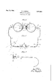
- Figure 1 is a front elevation, certain parts being shown in a partially disassembled position
- Fig. 2 is a top plan view of the frame shown in Fig. 1, certain parts being cut away to disclose-the construction more clearly;
- Fig. 3 is a side elevation of the frame shown in Fig. 1.
- a bridge the end portions of which are downwardly extended, as at 11, and outwardly inclined to merge at their lower ends into the rims 12.
- a guard arm 13 provided with a nose-pad 14, these parts being of any suitable detailed construction, but preferably having the guard arm of pliable material for purposes of adjustment.
- One end of the rim 12 terminates in an end piece 15 to which it is secured, and which in turn is secured to or formed integral with at its other end the adjacent downward extension of the bridge.
- This piece 15 is preferably horizontal and slightly above the horizontal axis of the rim, thereby being somewhat inclined with respect to the adjacent portions of the latter.
- the remaining end of the rim is provided with an end piece 16 which rests upon end piece 15 and registers therewith while abutting against the adjacent portion of the bridge extension. With these end pieces thus positioned, the corresponding ends of the rim are in alignment, and there are provided, as indicated in dotted lines at 17, registering openings to receive a screw 18 threaded into the part 15 by which the rim is held in closed position.
- a pair of curved and members 19 which merge into or are formed integral with the rim at points respectively above and below its horizontal axis.
- These members 19 are curved not only in a vertical plane, as shown in Fig. 1, but in a horizontal plane, as shown in Fig. 2, and, at their outer point of connection one with the other 20, are spaced both to the rear as well as laterally out from the adjacent-lens.
- the portion 20 is slotted and has pivotally secured therein, as by means of the screw 21, the adjacent perforated endof the temple 22.
- This pivotal point being positioned as shown, carries the temple itself further from the eye and shortens the necessary length of the temple, thus decreasing the leverage upon its pivot and permitting a temple of lighter construction to be used. Also, the rearward displacement of the pivotal point permits the temples to be folded readily into positions parallel with the planes of the lenses.
- a lens in combination, a lens, a member directly secured to the edge of said lens, an endpiece including two spaced parts secured to said member and converging outwardly and rearwardly to a point of interconnection to leave a space between said parts and said member, and a temple pivotally connected to said endpiece substantially at said point of interconnection.
- a lens in combination, a lens, a member secured tothe edge of said lens, a part rigidly connected to said member and extending downwardly and rearwardly, and a second part rigidly connected to said member at a point spaced from the connection between said last-mentioned part and said member and extending upwardly and rearwardly, said last two mentioned parts meeting and connected at a point spaced from the plane of said lens.
- a lens in combination, a lens, a member secured to the edge of said lens, a part connected to said member and extending downwardly and rearwardly, a second part connected to said member at a point spaced from the connection between said last-mentioned part and said member and extending upwardly and rearwardly, said last two mentioned parts meeting and connected at a point spaced from and to the rear of the plane of said lens, and a temple pivotally connected to said parts substantially at said point of connection.
- a lens in combination, a lens, a rim secured to said lens and encircling completely the edge of said lens, a V- shaped part having its spaced ends rigidly secured to said rim, said part and said rim forming the margin of an unobstructed space, a temple pivotally connected to said V-shaped part at the end thereof opposite said spaced ends, said rim being split at a point circumferentially spaced from said V-shaped part, and means for joining the ends of said rim to retain said lens therein.
- a lens in combination, a member in direct engagement with the edge of said lens, a V-shaped part having its spaced ends rigidly secured to said member so that said member bridges said ends, said part extending outwardly from said member and said lens and rearwardly to a point spaced from the plane of said lens, and a temple one end of which is pivotally connected to said part substantially atsaid point.
- a lens in combination, a lens, a member in direct engagement with the edge of said lens, a pliable part rigidly secured to said member at a point above the horizontal axis of said lens and extending in'a continuous curve downwardly, outwardly and rearwardly from said member and from said lens to a point sp ⁇ aced from the plane of said lens, and a temple pivotally secured to said part substantially at said point whereby said part is capable of adjustment both horizontally and vertically.
- a lens in combination, a lens, a rim member directly secured to the edge of said lens, a part rigidly secured to said member at a point spaced above the transverse axis of said lens, said part extending downwardly and outwardly from said lens and curving rearwardly to a point substantially spaced from the plane of said lens, and a temple pivotally secured to said part substantially at said point.
- a lens in combination, a lens, a rim member directly secured to said lens, a part secured to said rim member and extending outwardly and downwardly substantially in the same plane as said lens and rearwardly to a'point spaced from said lens, a part secured to said rim member. at a point spaced from the connection of said last-mentioned part and extending upwardly, outwardly and rearwardly to said point, means connecting said parts so that the rear ends thereof are spaced from each other, and a temple one end of which is disposed between said rear ends of said parts and pivotally connected theretoin said position.
- a lens in combination, a lens, a rim completely encircling said lens, a part rigidly connected to said rim and extending downwardly and outwardly from the periphery of said rim, a second part rigidly secured to said rim at a' point spaced from said last-mentioned part and extending upwardly and outwardly from the periphery of said rim, said parts meeting and being connected at a point spaced from the periphery of said rim, a temple pivotally connected to said parts substantially at said point of connection, said parts and said rim forming the margin of an unobstructed space, said rim being split at a point circumferentially spaced from both of said parts, and means for joining the ends of said rim to retain said lens therein.
Description
G. E. NERNEY 1,970,429
EYEGLASS CONSTRUCTION Filed.April 17, 1959 I NVENTOR BY 2 Zn/M7 A ATToRTvEYs Patented Aug. 14, I934 UNITED STATES PATENT OFFICE 1.570.429 nynqmss CONSTRUCTION Application April 11, 1930, Serial N6. 444,959
9 Claims. (01. 88-53) This invention relates to the construction of eyeglass frames.
One of the objects thereof is to provide a device of the above nature in which the material is so I disposed as to attain a high degree of strength without heavy construction. Another object is to provide a device of the above nature in which the parts are securely held in assembled relation and yet conveniently taken apart. Other objects are to providea thoroughly practical eyeglass frame of attractive appearance, and one in which the obstruction to vision is reduced to a minimum. Other objects will be in part obvious and in part pointed out hereinafter.
The invention accordingly consists in the features of construction, combinations of elements, and arrangements of parts which will be exemplified in the construction hereinafter described, and the scope of the application of which will be indicated in the subjoined claims.
In the accompanying drawing, in which is shown one of various possible embodiments of this invention,
Figure 1 is a front elevation, certain parts being shown in a partially disassembled position;
Fig. 2 is a top plan view of the frame shown in Fig. 1, certain parts being cut away to disclose-the construction more clearly; and
Fig. 3 is a side elevation of the frame shown in Fig. 1.
Similar reference characters refer to similar parts throughout the several views of the drawins.
In this drawing there is shown at 10 a bridge, the end portions of which are downwardly extended, as at 11, and outwardly inclined to merge at their lower ends into the rims 12. As the construction is identical upon both sides of the frame, that on one only will be described. On the extension 11 is formed a guard arm 13 provided with a nose-pad 14, these parts being of any suitable detailed construction, but preferably having the guard arm of pliable material for purposes of adjustment.
One end of the rim 12 terminates in an end piece 15 to which it is secured, and which in turn is secured to or formed integral with at its other end the adjacent downward extension of the bridge. This piece 15 is preferably horizontal and slightly above the horizontal axis of the rim, thereby being somewhat inclined with respect to the adjacent portions of the latter. The remaining end of the rim is provided with an end piece 16 which rests upon end piece 15 and registers therewith while abutting against the adjacent portion of the bridge extension. With these end pieces thus positioned, the corresponding ends of the rim are in alignment, and there are provided, as indicated in dotted lines at 17, registering openings to receive a screw 18 threaded into the part 15 by which the rim is held in closed position.
By this arrangement for the end joint of the rim, 9. high degree of security is attained. m the first place, the inclination of the end pieces with respect to the radiusv of the rim imposes on the screw a stress inclined with respect to its axis if the rim tends to open, thus bringing into play the strength of the screw itself and not depending solely uponthe threads cut therein. In the second place, thesolid support of the end piece 15 at both ends, and the wedging of the end piece 16 into position between the bridgeand lens, give a partially interlocking relation which also coacts with the screw in holding the rim in 7 closed condition. a
At the outer portions of the rims 12 there are provided a pair of curved and members 19 which merge into or are formed integral with the rim at points respectively above and below its horizontal axis. These members 19 are curved not only in a vertical plane, as shown in Fig. 1, but in a horizontal plane, as shown in Fig. 2, and, at their outer point of connection one with the other 20, are spaced both to the rear as well as laterally out from the adjacent-lens. The portion 20 is slotted and has pivotally secured therein, as by means of the screw 21, the adjacent perforated endof the temple 22. This pivotal point, being positioned as shown, carries the temple itself further from the eye and shortens the necessary length of the temple, thus decreasing the leverage upon its pivot and permitting a temple of lighter construction to be used. Also, the rearward displacement of the pivotal point permits the temples to be folded readily into positions parallel with the planes of the lenses.
It is to be particularly noted that the end members 19, although sufllciently rigid to maintain the form into which they are placed, are nevertheless of such pliable nature that they may be manually adjusted when the frame is fitted. They may, for example, as shown in Fig. 2, be adjusted inwardly, as indicated in the dotted lines 23, or outwardly, if desired, so as to vary the dis- 105 tance between the temples without materially affecting the length ofthe temples or necessitating the bending of the temple bars. Furthermore, they may be adjusted upwardly or downwardly, as indicated at 24 in Fi 3, thus varying the in- 110 clination of the temple bars with respect to the plane of the lenses as desired. These adjustments, furthermore, may be readily accomplished without detracting from the symmetry and attractive appearance of the frame=as a whole.
By the above construction, not only are the above advantages achieved, but a high degree of visibility in all directions is attained. As indicated by the dotted lines in Fig. 2, throughout a substantial angle the opening formed by the members 19 permits unobstructed vision in a lateral direction without lessening the strength and rigidity of the connection between the rim and the ear-loop of the temple. Furthermore, and in a somewhat similar way, the open construction between the parts 11 and neighboring portions of the rim 12 gains a high degree of strength and stiffness and yet avoids obstruction of vision at this point. These features are particularly important in such relations as the driving of motor cars, in which even slight obstruction of vision is often dangerous.
It will thus be seen that there is provided a frame in which the several objects of this invention are achieved in an essentially practical manner without detracting from its appearance.
As many possible embodiments may be made of the above invention, and as many changes might be ,made in the embodiment above set forth, it istobe understood that all matter hereinbefore set forth or shown in the accompanying drawing is to be interpreted as illustrative and not in a limiting sense.
I claim:
1. In eyeglass construction, in combination, a lens, a member directly secured to the edge of said lens, an endpiece including two spaced parts secured to said member and converging outwardly and rearwardly to a point of interconnection to leave a space between said parts and said member, and a temple pivotally connected to said endpiece substantially at said point of interconnection.
2. In eyeglass construction, in combination, a lens, a member secured tothe edge of said lens, a part rigidly connected to said member and extending downwardly and rearwardly, and a second part rigidly connected to said member at a point spaced from the connection between said last-mentioned part and said member and extending upwardly and rearwardly, said last two mentioned parts meeting and connected at a point spaced from the plane of said lens.
3. In eyeglass construction, in combination, a lens, a member secured to the edge of said lens, a part connected to said member and extending downwardly and rearwardly, a second part connected to said member at a point spaced from the connection between said last-mentioned part and said member and extending upwardly and rearwardly, said last two mentioned parts meeting and connected at a point spaced from and to the rear of the plane of said lens, and a temple pivotally connected to said parts substantially at said point of connection.
4. In construction for eyeglasses, in combination, a lens, a rim secured to said lens and encircling completely the edge of said lens, a V- shaped part having its spaced ends rigidly secured to said rim, said part and said rim forming the margin of an unobstructed space, a temple pivotally connected to said V-shaped part at the end thereof opposite said spaced ends, said rim being split at a point circumferentially spaced from said V-shaped part, and means for joining the ends of said rim to retain said lens therein.
5. In construction for eyeglasses, in combination, a lens, a member in direct engagement with the edge of said lens, a V-shaped part having its spaced ends rigidly secured to said member so that said member bridges said ends, said part extending outwardly from said member and said lens and rearwardly to a point spaced from the plane of said lens, and a temple one end of which is pivotally connected to said part substantially atsaid point.
6. In construction for eyeglasses, in combination, a lens, a member in direct engagement with the edge of said lens, a pliable part rigidly secured to said member at a point above the horizontal axis of said lens and extending in'a continuous curve downwardly, outwardly and rearwardly from said member and from said lens to a point sp\aced from the plane of said lens, and a temple pivotally secured to said part substantially at said point whereby said part is capable of adjustment both horizontally and vertically.
7. In construction for eyeglasses, in combination, a lens, a rim member directly secured to the edge of said lens, a part rigidly secured to said member at a point spaced above the transverse axis of said lens, said part extending downwardly and outwardly from said lens and curving rearwardly to a point substantially spaced from the plane of said lens, and a temple pivotally secured to said part substantially at said point.
8. In construction for eyeglasses, in combination, a lens, a rim member directly secured to said lens, a part secured to said rim member and extending outwardly and downwardly substantially in the same plane as said lens and rearwardly to a'point spaced from said lens, a part secured to said rim member. at a point spaced from the connection of said last-mentioned part and extending upwardly, outwardly and rearwardly to said point, means connecting said parts so that the rear ends thereof are spaced from each other, and a temple one end of which is disposed between said rear ends of said parts and pivotally connected theretoin said position.
9. In eyeglass construction, in combination, a lens, a rim completely encircling said lens, a part rigidly connected to said rim and extending downwardly and outwardly from the periphery of said rim, a second part rigidly secured to said rim at a' point spaced from said last-mentioned part and extending upwardly and outwardly from the periphery of said rim, said parts meeting and being connected at a point spaced from the periphery of said rim, a temple pivotally connected to said parts substantially at said point of connection, said parts and said rim forming the margin of an unobstructed space, said rim being split at a point circumferentially spaced from both of said parts, and means for joining the ends of said rim to retain said lens therein.
GEORGE E. NERNEY.
Priority Applications (2)
| Application Number | Priority Date | Filing Date | Title |
|---|---|---|---|
| US444959A US1970429A (en) | 1930-04-17 | 1930-04-17 | Eyeglass construction |
| US725297A US2071893A (en) | 1930-04-17 | 1934-05-12 | Eyeglass construction |
Applications Claiming Priority (1)
| Application Number | Priority Date | Filing Date | Title |
|---|---|---|---|
| US444959A US1970429A (en) | 1930-04-17 | 1930-04-17 | Eyeglass construction |
Publications (1)
| Publication Number | Publication Date |
|---|---|
| US1970429A true US1970429A (en) | 1934-08-14 |
Family
ID=23767077
Family Applications (1)
| Application Number | Title | Priority Date | Filing Date |
|---|---|---|---|
| US444959A Expired - Lifetime US1970429A (en) | 1930-04-17 | 1930-04-17 | Eyeglass construction |
Country Status (1)
| Country | Link |
|---|---|
| US (1) | US1970429A (en) |
Cited By (1)
| Publication number | Priority date | Publication date | Assignee | Title |
|---|---|---|---|---|
| US20090310080A1 (en) * | 2008-04-14 | 2009-12-17 | Dellapina Maria L | Eyeglass frames for people with special needs |
-
1930
- 1930-04-17 US US444959A patent/US1970429A/en not_active Expired - Lifetime
Cited By (2)
| Publication number | Priority date | Publication date | Assignee | Title |
|---|---|---|---|---|
| US20090310080A1 (en) * | 2008-04-14 | 2009-12-17 | Dellapina Maria L | Eyeglass frames for people with special needs |
| US7810924B2 (en) | 2008-04-14 | 2010-10-12 | Dellapina Maria L | Eyeglass frames for people with special needs |
Similar Documents
| Publication | Publication Date | Title |
|---|---|---|
| US2280354A (en) | Binoculars | |
| EP0406245A1 (en) | Vertical plane adjusting mechanism for eyeglasses | |
| US1970429A (en) | Eyeglass construction | |
| US2304504A (en) | Dual lens construction | |
| US2071893A (en) | Eyeglass construction | |
| US1779789A (en) | Ophthalmic mounting | |
| US1510850A (en) | Motorist's goggles | |
| US2075020A (en) | Goggles, spectacles, or the like | |
| US1742049A (en) | Dimmer glass | |
| US1967434A (en) | Ophthalmic mounting | |
| US584765A (en) | Isaac alexander | |
| US1625614A (en) | Spectacles | |
| US1935433A (en) | Ophthalmic mounting | |
| US1975894A (en) | Folding spectacles | |
| US1691789A (en) | Spectacles | |
| US786442A (en) | Attachment for spectacles. | |
| US2041638A (en) | Spectacle frames | |
| US1960791A (en) | Eyeglass construction | |
| US2346709A (en) | Eye shield for ophthalmic mountings | |
| US291778A (en) | Spectacles | |
| US550864A (en) | Eyeglasses ob | |
| US1970079A (en) | Spectacles or eyeglasses | |
| US1842377A (en) | Ophthalmic mounting | |
| US1959396A (en) | Spectacles | |
| US2130692A (en) | Eyeglass |