US20020184866A1 - Tractor-supported lawnmower having mowers movable up and down - Google Patents
Tractor-supported lawnmower having mowers movable up and down Download PDFInfo
- Publication number
- US20020184866A1 US20020184866A1 US10/188,219 US18821902A US2002184866A1 US 20020184866 A1 US20020184866 A1 US 20020184866A1 US 18821902 A US18821902 A US 18821902A US 2002184866 A1 US2002184866 A1 US 2002184866A1
- Authority
- US
- United States
- Prior art keywords
- tractor
- support arm
- lawnmower
- axis
- mower
- Prior art date
- Legal status (The legal status is an assumption and is not a legal conclusion. Google has not performed a legal analysis and makes no representation as to the accuracy of the status listed.)
- Granted
Links
Images


Classifications
-
- A—HUMAN NECESSITIES
- A01—AGRICULTURE; FORESTRY; ANIMAL HUSBANDRY; HUNTING; TRAPPING; FISHING
- A01D—HARVESTING; MOWING
- A01D75/00—Accessories for harvesters or mowers
- A01D75/30—Arrangements for trailing two or more mowers
- A01D75/306—Arrangements for trailing two or more mowers for lawn mowers positioned one behind the other or side by side
Definitions
- This invention relates to a lawnmower having a tractor and mowers movable up and down on the tractor, and, more particularly, it relates to a tractor and mower assembly of the gang type wherein the mowers are movable up and down and they maintain a constant horizontally related spacing between the mowers and relative to the tractor.
- Those mowers are commonly reel mowers and they are arranged in side-by-side relationship along one common reel axis and in rows.
- the mowers will inherently move toward each other during their arcuate up and down movement, and there must be sufficient space between adjacent mowers in each row in order to avoid collisions with each other. Therefore, in an arrangement where the mowing mowers are adequately spaced apart in one row, they leave an unmowed swath between adjacent mowers.
- the mower of another row is thus positioned to mow that unmowed swath, and that mower must be of a length sufficient to mow that unmowed swath, and all the mowers are of that length.
- the length of the mowers is determined by the required non-colliding spacing between adjacent mowers, and the mowers must be sufficiently long to permit the required spacing therebetween in order to avoid colliding upon up and down movement. To avoid collisions, the mowers must each be of a minimum length.
- mowers of only a maximum length that is, a short mower, will best conform to the irregular contour of the ground over which it is riding. That results in a short mower being more efficient in complete and neat mowing, compared to a mower that must be of a longer length, such as that which is long to avoid the collision mentioned above.
- this invention provides for a gang mower wherein the mowers move up and down in parallel vertical planes and thereby maintain a constant horizontal distance away from the respective vertical plane on which each mower is located.
- the mowers avoid colliding with each other.
- the mowers are supported to avoid being moved laterally relative to each other and the tractor, in addition to supporting the mower for up and down movement.
- the mowers of this invention are operatively maintained in their respective mowing positions relative to the tractor such that they mow along one vertical plane even though they are riding up and down over irregular or contoured ground, and they therefore do not move horizontally toward and away relative to the tractor, and the method is such that the mowers mow only in swathes parallel to the tractor, and they do not move toward each other.
- This invention accomplishes the aforementioned and does so in conjunction with power lift mechanism which can control up and down movement of the mowers and which does not hinder the above-mentioned horizontal positioning of the mowers.
- This invention employs a floating pivot which achieves the mower placement mentioned, and the entire arrangement is of a sturdy construction to provide the optimum pivotal support of the mower relative to the tractor.
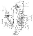
- FIG. 1 is an exploded front perspective view of a portion of this invention, showing a fragment of a tractor in dot-dash 3 lines, for clarity.
- FIG. 2 is a perspective view, similar to FIG. 1 but with parts added thereto, with the parts assembled, and with the complete mowers added thereto.
- FIG. 3 is a rear perspective view of FIG. 2, and without the complete mowers.
- FIG. 4 is a side elevational view of FIG. 2, but on a reduced scale and with a fragment of a tire of the tractor added thereto.
- FIG. 5 is a top plan view of FIG. 2.
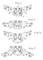
- FIGS. 6 - 9 are rear elevational views showing the parts in four different operative positions.
- FIG. 10 is a front elevational view with the parts in the raised operative position of FIG. 8.
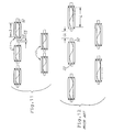
- FIG. 11 is a top plan view of this invention's layout of five mowers of a gang with short mowers.
- FIG. 12 is a top plan view of the prior art layout of five mowers of a gang with long mowers.
- This gang-type lawnmower assembly has a tractor, generally designated 10 , and lawnmowers, generally designated 11 , supported on the tractor. There can be an odd number of mowers, such as three or five, as seen in FIG. 11 with the five mowers 11 . Of course, the tractor rides on the ground to be mowed, and the mowers are all of one identical construction, and they too ride on the ground while being propelled by the tractor which itself is self-propelled in the usual manner.
- tractor frame beam 12 and an upright frame plate 13 which has two spaced apart openings 14 therethrough.
- Mounting studs 16 serve as pivot supports and extend rearwardly and horizontally as part of the tractor frame, and each stud 16 presents a horizontal pivot axis A.
- the tractor has a longitudinal axis T extending fore-and-aft of the tractor and that is of the mowing direction of the lawnmower.
- the axes A are parallel to and on laterally opposite sides of the tractor axis T.
- the drawings show two side or wing mowers 11 , symmetrically disposed and arranged, and there is a central mower, identical in structure to the shown mowers, and they are all positioned as seen in FIGS. 2 and 11.
- FIGS. 1 and 3 there is a pivoting support 17 pivotally mounted on each stud or post 16 , and the support 17 is in the form of a crank with a tubular sleeve 18 , and a connecting offset portion 19 , and a lower tubular sleeve 21 .
- the two tubular sleeves 18 are respectively snugly pivotally mounted on the respective cylindrical post 16 , and the two cranks 17 are suitably axially fixed with the posts 16 by axially restrictive assembly with pins, such as pin 22 , which extend through the respective posts 16 , but the cranks 17 are free to pivot and swing side-to-side on the respective post 16 .
- the forward end of the tube 21 extends through a respective one of the openings 14 in the tractor frame, and the openings 14 are shaped and elongated sufficiently to allow for the swinging action of the sleeve 21 .
- cranks 17 extend downwardly so that the swinging movement is side-to-side on the tractor, in pendulum fashion, and that is laterally of the tractor fore and-aft axis T. As such, the crank presents a floating axis F.
- Each laterally or wing positioned mower 11 has a pivotal support arm 23 with extending end 24 at the side or laterally of the tractor. As shown, the end 24 has a sleeve 26 attached thereto and extending in the fore-and-aft direction. Each mower assembly includes a connection of a push arm 27 which is snugly disposed in the sleeve 26 to rotate therein but is restricted by the shown assembly.
- each mower 11 is a reel mower and is movably supported on the ground G by front rollers 28 and rear rollers 29 .
- FIG. 4 further shows that the tractor's usual tire 31 is also on the ground G and that is a common ground level for the tractor and the mowers in their respective operating positions when on the same level of ground.
- the laterally inward end of the arm 23 relative to the fore-and-aft tractor axis T has affixed thereto a cylindrical shaft 32 which extends horizontally and parallel to the axis T.
- Each shaft 32 is snugly received in a respective one of the two sleeves 21 and is pivotally supported therein.
- a pin 33 extends through the shaft 32 to axially secure the shaft 32 relative to the sleeve 21 .
- the shaft or posts 32 are therefore respectively piloted on the floating axes F, and thus the extending ends 24 of the support arms 23 , along with the attached mowers 11 , are able to move up and down. That movement may be as induced by irregular ground contour over which the mowers ride, that is, ground rises and depressions. Additionally, with the cranks 17 being swingable about their axes A to thereby laterally displace the floating axes F, the arms 23 move laterally of the tractor and its axis T.
- each arm 23 Affixed to each arm 23 is a cam plate 34 which can pivot about the axis F in step with the pivot of the respective arm 23 about the axis F.
- FIGS. 1 and 10 show that each plate 34 has a top end 36 and a bottom end 37 and those ends are equally positioned relative to the pivot axis F.
- the ends 36 and 37 have a respective cam surface 38 and 39 .
- the tractor 10 has two blocks 41 and 42 affixed thereon, and FIG. 10 shows they present four upright surfaces 43 , 44 , 45 and 46 , each of which extends vertically and is faced laterally outwardly of the respective two sides of the tractor, as shown.
- FIGS. 8 and 10 show the highest mow position, that is when the mower 11 is on a rise in the ground and it responds by moving up to the position shown. In that action, surface 38 of the plate 34 abuts the tractor surface 44 and that causes the movable pivot axis F to swing laterally along arc AX which is centered on axis A.
- That pendulum swinging action of axis F creates the laterally outward movement of the laterally inward end of the support arm 23 , and the non-arcuate movement of the mower 11 which is articularly attached at axis M defined by sleeve 26 .
- axis M In the showing in FIG. 10 and assuming the prior art condition of the absence of the floating pivot F, in the raised position shown, axis M would move along arc MX. From its lowered and starting position M′, axis M would move horizontally and laterally inwardly relative to the tractor axis T and the vertical plane V by an undesirable distance X.
- the distance from the axis F to the cam 38 or 39 is made to vary according to the pivoted positions achieved, and that may be from about three to three and one-third inches, and the distance from the axis F to the axis A can be five inches.
- the distance from axis F to the contact with the cam 38 , and the length of the crank 17 from axes A to F, are dimensioned such that there is no horizontal movement of the axis M. Those two dimensions are only a minor or very small fraction compared to the length of the support arm 23 , and thereby the desired horizontal control of the mower is achieved.
- a tension spring 47 is suitably connected with the arm 23 to yielding urge the arm 23 horizontally inwardly relative to the tractor axis T, and thereby always hold either or both surfaces 38 and 39 of the plate 34 against the respective surfaces 43 - 46 , as is apparent.
- the mowers 11 are shown to include a cutting reel 49 and a connecting bail 51 which interconnects with the respective arms 23 .
- Reel driving motors 52 and counterweights 53 are on the axial ends of the reels 49 , and, because of the added length they present, they must be negotiated in the up and down movement of the mowers to avoid the collisions mentioned.
- FIG. 11 shows that with this invention and in the vertical up and down movement of the mowers 11 , the mowers 11 can be placed close together with only a clearance CS therebetween, and thus the length of those mowers can be short mowers S, of say eighteen inches, as desired.
- FIG. 12 shows the necessary greater clearance CL and the consequent undesirable longer length mowers L, of say twenty-six inches as required by the prior art.
- a hydraulic lift cylinder assembly 54 pivotally mounted on a horizontally extending post 56 on the tractor 10 .
- the cylinder assembly 54 has its rod 57 axially movable, and it presents a cross sleeve 58 which carries a cross pin 59 .
- the extending end 24 of the arm 23 has two plates 61 affixed thereto and they present horizontal slots 62 which slidably receive the pin 59 .
- extension and contraction of the cylinder assembly 54 can cause the pin 59 to slide in the slots 62 in a lost motion connection between the cylinder assemblies and the arms 23 .
- the up and down movement of the mowers 11 can be accomplished without overcoming the cylinder assembly 54 because of how they are connected.
- the cylinder assembly will cause the pins 59 to slid along the slots 62 to either end thereof, such as to the distal end for raising the mowers 11 , as seen in FIG. 6, and that could be the self-propelled transport position for the entire lawnmower.
- the mower 11 In the FIG. 9 position, the mower 11 is limited by the cylinder assembly 54 in the lowest mowing position, for instance.
- Posts 56 are on axes A.
- FIGS. 1 - 5 and 7 show the lawnmower in the level or a neutral position where it will mow when the tractor 10 and the mower 11 are on the common level ground G.
- the pivot axis F and the support arm axis M are on the same horizontal level.
- the spring 47 has urged and will hold the two floating axes F closest toward each other, and the cranks 17 are disposed to be angled inwardly toward each other as seen in FIGS. 3 and 7. That provides for optimum swing action of the floating axis F because the sleeve 21 of the crank 17 swings through the lowermost portion of the arcuate circle on which it is centered, and thereby produces maximum horizontal movement of axis F as desired.
- the method invention herein is that of providing a floating axis F, in a pendulum arrangement for movement transverse and relative to the tractor fore-and-aft axis, and arranging the cams 38 and 39 along with the four fixed tractor surfaces, and then moving the mowers up and down to create the cam action and the horizontal movement of the axis F. All to achieve the vertically constant positioning of the mowers 11 and the constant spacing between the mowers, even when the mowers move up and down about a pivot axis.
- the arrangement is such that the axes A and F and the surfaces 43 - 46 are all respectively substantially vertically aligned. Also, in the neutral position, such as shown in FIG. 7, the support 17 and the arm 23 substantially form a right angle therebetween. In that position, the spring 47 always positions the arms 23 to have the axes F innermost on the tractor and thus closest to each other.
Abstract
Description
- This application is a continuation of U.S. patent application Ser. No. 09/652,846, filed Aug. 31, 2000. The disclosure of the above application is incorporated herein by reference.
- This invention relates to a lawnmower having a tractor and mowers movable up and down on the tractor, and, more particularly, it relates to a tractor and mower assembly of the gang type wherein the mowers are movable up and down and they maintain a constant horizontally related spacing between the mowers and relative to the tractor.
- Lawnmowers which have tractors supporting mowers with up and down movement relative to the tractor are known in the prior art. That type of gang mower is shown in U.S. Pat. Nos. 3,511,033 and 3,905,180, which are patents owned by the assignee herein. That art has a tractor pivotally supporting a mower support arm on which mowers are mounted and can move up and down either in response to riding over uneven ground or by powered lift and lowering cylinders connected to the support arms. In those arrangements, the support arms pivot about an axis to cause the extending ends of the support arms, along with the mowers attached to the extending ends, to move up and down along an arc centered about the pivot axis.
- Those mowers are commonly reel mowers and they are arranged in side-by-side relationship along one common reel axis and in rows. The mowers will inherently move toward each other during their arcuate up and down movement, and there must be sufficient space between adjacent mowers in each row in order to avoid collisions with each other. Therefore, in an arrangement where the mowing mowers are adequately spaced apart in one row, they leave an unmowed swath between adjacent mowers. The mower of another row is thus positioned to mow that unmowed swath, and that mower must be of a length sufficient to mow that unmowed swath, and all the mowers are of that length.
- The length of the mowers is determined by the required non-colliding spacing between adjacent mowers, and the mowers must be sufficiently long to permit the required spacing therebetween in order to avoid colliding upon up and down movement. To avoid collisions, the mowers must each be of a minimum length.
- In contrast to the foregoing, mowers of only a maximum length, that is, a short mower, will best conform to the irregular contour of the ground over which it is riding. That results in a short mower being more efficient in complete and neat mowing, compared to a mower that must be of a longer length, such as that which is long to avoid the collision mentioned above.
- Accordingly, it is the object of this invention to provide a gang type lawnmower with a relative short length for each mower in the gang, and thereby provide for improved mowing, compared to the prior art.
- Also, when the mower is moving up and down by riding and mowing over irregular ground, and when under the control of the lift mechanism, this invention provides for a gang mower wherein the mowers move up and down in parallel vertical planes and thereby maintain a constant horizontal distance away from the respective vertical plane on which each mower is located. Thus the mowers avoid colliding with each other. In accomplishing this objective, the mowers are supported to avoid being moved laterally relative to each other and the tractor, in addition to supporting the mower for up and down movement.
- Still further, the aforementioned object is accomplished automatically by the lawnmower assembly itself, and operator control or attention is not required.
- Still further, the mowers of this invention are operatively maintained in their respective mowing positions relative to the tractor such that they mow along one vertical plane even though they are riding up and down over irregular or contoured ground, and they therefore do not move horizontally toward and away relative to the tractor, and the method is such that the mowers mow only in swathes parallel to the tractor, and they do not move toward each other.
- This invention accomplishes the aforementioned and does so in conjunction with power lift mechanism which can control up and down movement of the mowers and which does not hinder the above-mentioned horizontal positioning of the mowers.
- This invention employs a floating pivot which achieves the mower placement mentioned, and the entire arrangement is of a sturdy construction to provide the optimum pivotal support of the mower relative to the tractor.
- FIG. 1 is an exploded front perspective view of a portion of this invention, showing a fragment of a tractor in dot-dash 3 lines, for clarity.
- FIG. 2 is a perspective view, similar to FIG. 1 but with parts added thereto, with the parts assembled, and with the complete mowers added thereto.
- FIG. 3 is a rear perspective view of FIG. 2, and without the complete mowers.
- FIG. 4 is a side elevational view of FIG. 2, but on a reduced scale and with a fragment of a tire of the tractor added thereto.
- FIG. 5 is a top plan view of FIG. 2.
- FIGS. 6-9 are rear elevational views showing the parts in four different operative positions.
- FIG. 10 is a front elevational view with the parts in the raised operative position of FIG. 8.
- FIG. 11 is a top plan view of this invention's layout of five mowers of a gang with short mowers.
- FIG. 12 is a top plan view of the prior art layout of five mowers of a gang with long mowers.
- As should be understood when viewing the drawings, the parts of the embodiment of this invention are shown in different positions and in full lines while, for clarity, the tractor is shown in dot-lines. Also, the following description refers to the drawings, and thereby the method of avoiding the lateral movement of the mowers relative to the tractor is inherent in that description and therefore is disclosed herein.
- This gang-type lawnmower assembly has a tractor, generally designated 10, and lawnmowers, generally designated 11, supported on the tractor. There can be an odd number of mowers, such as three or five, as seen in FIG. 11 with the five mowers 11. Of course, the tractor rides on the ground to be mowed, and the mowers are all of one identical construction, and they too ride on the ground while being propelled by the tractor which itself is self-propelled in the usual manner.
- There is a
tractor frame beam 12 and anupright frame plate 13 which has two spaced apart openings 14 therethrough.Mounting studs 16 serve as pivot supports and extend rearwardly and horizontally as part of the tractor frame, and eachstud 16 presents a horizontal pivot axis A. - It will be understood that the tractor has a longitudinal axis T extending fore-and-aft of the tractor and that is of the mowing direction of the lawnmower. Thus the axes A are parallel to and on laterally opposite sides of the tractor axis T. It will also be understood that the drawings show two side or wing mowers 11, symmetrically disposed and arranged, and there is a central mower, identical in structure to the shown mowers, and they are all positioned as seen in FIGS. 2 and 11.
- As understood from FIGS. 1 and 3, there is a
pivoting support 17 pivotally mounted on each stud orpost 16, and thesupport 17 is in the form of a crank with atubular sleeve 18, and a connectingoffset portion 19, and a lowertubular sleeve 21. The twotubular sleeves 18 are respectively snugly pivotally mounted on the respectivecylindrical post 16, and the twocranks 17 are suitably axially fixed with theposts 16 by axially restrictive assembly with pins, such aspin 22, which extend through therespective posts 16, but thecranks 17 are free to pivot and swing side-to-side on therespective post 16. The forward end of thetube 21 extends through a respective one of the openings 14 in the tractor frame, and the openings 14 are shaped and elongated sufficiently to allow for the swinging action of thesleeve 21. - In that arrangement, the
cranks 17 extend downwardly so that the swinging movement is side-to-side on the tractor, in pendulum fashion, and that is laterally of the tractor fore and-aft axis T. As such, the crank presents a floating axis F. - Each laterally or wing positioned mower 11 has a
pivotal support arm 23 with extendingend 24 at the side or laterally of the tractor. As shown, theend 24 has asleeve 26 attached thereto and extending in the fore-and-aft direction. Each mower assembly includes a connection of apush arm 27 which is snugly disposed in thesleeve 26 to rotate therein but is restricted by the shown assembly. - It will therefore be seen that each mower 11 is a reel mower and is movably supported on the ground G by
front rollers 28 andrear rollers 29. FIG. 4 further shows that the tractor's usual tire 31 is also on the ground G and that is a common ground level for the tractor and the mowers in their respective operating positions when on the same level of ground. - The laterally inward end of the
arm 23 relative to the fore-and-aft tractor axis T, has affixed thereto acylindrical shaft 32 which extends horizontally and parallel to the axis T. Eachshaft 32 is snugly received in a respective one of the twosleeves 21 and is pivotally supported therein. Apin 33 extends through theshaft 32 to axially secure theshaft 32 relative to thesleeve 21. - The shaft or
posts 32 are therefore respectively piloted on the floating axes F, and thus the extendingends 24 of thesupport arms 23, along with the attached mowers 11, are able to move up and down. That movement may be as induced by irregular ground contour over which the mowers ride, that is, ground rises and depressions. Additionally, with thecranks 17 being swingable about their axes A to thereby laterally displace the floating axes F, thearms 23 move laterally of the tractor and its axis T. - Affixed to each
arm 23 is acam plate 34 which can pivot about the axis F in step with the pivot of therespective arm 23 about the axis F. FIGS. 1 and 10 show that eachplate 34 has atop end 36 and a bottom end 37 and those ends are equally positioned relative to the pivot axis F. Theends 36 and 37 have arespective cam surface - The tractor 10 has two
blocks 41 and 42 affixed thereon, and FIG. 10 shows they present four upright surfaces 43, 44, 45 and 46, each of which extends vertically and is faced laterally outwardly of the respective two sides of the tractor, as shown. FIGS. 8 and 10 show the highest mow position, that is when the mower 11 is on a rise in the ground and it responds by moving up to the position shown. In that action,surface 38 of theplate 34 abuts the tractor surface 44 and that causes the movable pivot axis F to swing laterally along arc AX which is centered on axis A. That pendulum swinging action of axis F creates the laterally outward movement of the laterally inward end of thesupport arm 23, and the non-arcuate movement of the mower 11 which is articularly attached at axis M defined bysleeve 26. - In the showing in FIG. 10 and assuming the prior art condition of the absence of the floating pivot F, in the raised position shown, axis M would move along arc MX. From its lowered and starting position M′, axis M would move horizontally and laterally inwardly relative to the tractor axis T and the vertical plane V by an undesirable distance X.
- With the floating pivot F, under that raised condition, the floating pivot F will move horizontally and laterally outwardly by that distance X. The length of the
support arm 23 and the distance from axis F to thecontact surface 38, and conversely 39, causes the floating pivot F to be displaced a horizontal distance to compensate for the prior art horizontal movement of the axis M for the distance X, all to achieve the result that the axis M remains on the vertical plane V. Where the length of thesupport arm 23 is fourteen inches from axis F to axis M, the distance from the axis F to thecam - Of course, if the axis M were lowered, such as when the mower 11 rides down into a ground depression, then the downward pivot of the
arm 23 would cause thecam surface 39 to abut the fixed tractor surface 46, such as in the FIG. 9 condition, then the floating pivot F would again move horizontally outwardly by a distance X to again keep the axis M on its original vertical plane during straight-ahead lawnmower movement. In those conditions of up or down mower movement, if and whensupport arm 23 pivots through an angle BETA, axis F pivots about axis A through an angle ALPHA. The distance from axis F to the contact with thecam 38, and the length of thecrank 17 from axes A to F, are dimensioned such that there is no horizontal movement of the axis M. Those two dimensions are only a minor or very small fraction compared to the length of thesupport arm 23, and thereby the desired horizontal control of the mower is achieved. - A
tension spring 47 is suitably connected with thearm 23 to yielding urge thearm 23 horizontally inwardly relative to the tractor axis T, and thereby always hold either or bothsurfaces plate 34 against the respective surfaces 43-46, as is apparent. - The entire construction is in left and right hand duplication, or mirror image on the tractor 10. So another
support 17,arm 23, floating pivot F, andplate 34 are provided, as shown. Also, there is only asingle spring 47 which is connected with the twoarms 23 through ananchor 48 on eacharm 23. It will be obvious that the up and down mower movement described, and the consequent described responses, can be for only one, or for more, of the mowers 11 and their respective connecting parts. - The mowers 11 are shown to include a cutting
reel 49 and a connectingbail 51 which interconnects with therespective arms 23. Reel drivingmotors 52 andcounterweights 53 are on the axial ends of thereels 49, and, because of the added length they present, they must be negotiated in the up and down movement of the mowers to avoid the collisions mentioned. - FIG. 11 shows that with this invention and in the vertical up and down movement of the mowers 11, the mowers 11 can be placed close together with only a clearance CS therebetween, and thus the length of those mowers can be short mowers S, of say eighteen inches, as desired. In the prior art assembly, FIG. 12 shows the necessary greater clearance CL and the consequent undesirable longer length mowers L, of say twenty-six inches as required by the prior art.
- To power lift and lower the mowers 11, there is shown a hydraulic
lift cylinder assembly 54 pivotally mounted on a horizontally extendingpost 56 on the tractor 10. Thecylinder assembly 54 has its rod 57 axially movable, and it presents across sleeve 58 which carries across pin 59. The extendingend 24 of thearm 23 has two plates 61 affixed thereto and they presenthorizontal slots 62 which slidably receive thepin 59. In the arrangement, extension and contraction of thecylinder assembly 54 can cause thepin 59 to slide in theslots 62 in a lost motion connection between the cylinder assemblies and thearms 23. Thus, the up and down movement of the mowers 11 can be accomplished without overcoming thecylinder assembly 54 because of how they are connected. However, when it is desired to raise or lower the mowers 11 under the force applied by thecylinder assembly 54, then the cylinder assembly will cause thepins 59 to slid along theslots 62 to either end thereof, such as to the distal end for raising the mowers 11, as seen in FIG. 6, and that could be the self-propelled transport position for the entire lawnmower. In the FIG. 9 position, the mower 11 is limited by thecylinder assembly 54 in the lowest mowing position, for instance.Posts 56 are on axes A. - FIGS. 1-5 and 7 show the lawnmower in the level or a neutral position where it will mow when the tractor 10 and the mower 11 are on the common level ground G. In that position, the pivot axis F and the support arm axis M are on the same horizontal level. At that condition, the
spring 47 has urged and will hold the two floating axes F closest toward each other, and thecranks 17 are disposed to be angled inwardly toward each other as seen in FIGS. 3 and 7. That provides for optimum swing action of the floating axis F because thesleeve 21 of thecrank 17 swings through the lowermost portion of the arcuate circle on which it is centered, and thereby produces maximum horizontal movement of axis F as desired. - The method invention herein is that of providing a floating axis F, in a pendulum arrangement for movement transverse and relative to the tractor fore-and-aft axis, and arranging the
cams - The arrangement is such that the axes A and F and the surfaces 43-46 are all respectively substantially vertically aligned. Also, in the neutral position, such as shown in FIG. 7, the
support 17 and thearm 23 substantially form a right angle therebetween. In that position, thespring 47 always positions thearms 23 to have the axes F innermost on the tractor and thus closest to each other.
Claims (23)
Priority Applications (1)
| Application Number | Priority Date | Filing Date | Title |
|---|---|---|---|
| US10/188,219 US6698171B2 (en) | 2000-08-31 | 2002-07-01 | Tractor-supported lawnmower having mowers movable up and down |
Applications Claiming Priority (2)
| Application Number | Priority Date | Filing Date | Title |
|---|---|---|---|
| US09/652,846 US6412258B1 (en) | 2000-08-31 | 2000-08-31 | Tractor-supported lawnmower having mowers movable up and down |
| US10/188,219 US6698171B2 (en) | 2000-08-31 | 2002-07-01 | Tractor-supported lawnmower having mowers movable up and down |
Related Parent Applications (1)
| Application Number | Title | Priority Date | Filing Date |
|---|---|---|---|
| US09/652,846 Continuation US6412258B1 (en) | 2000-08-31 | 2000-08-31 | Tractor-supported lawnmower having mowers movable up and down |
Publications (2)
| Publication Number | Publication Date |
|---|---|
| US20020184866A1 true US20020184866A1 (en) | 2002-12-12 |
| US6698171B2 US6698171B2 (en) | 2004-03-02 |
Family
ID=24618409
Family Applications (2)
| Application Number | Title | Priority Date | Filing Date |
|---|---|---|---|
| US09/652,846 Expired - Lifetime US6412258B1 (en) | 2000-08-31 | 2000-08-31 | Tractor-supported lawnmower having mowers movable up and down |
| US10/188,219 Expired - Lifetime US6698171B2 (en) | 2000-08-31 | 2002-07-01 | Tractor-supported lawnmower having mowers movable up and down |
Family Applications Before (1)
| Application Number | Title | Priority Date | Filing Date |
|---|---|---|---|
| US09/652,846 Expired - Lifetime US6412258B1 (en) | 2000-08-31 | 2000-08-31 | Tractor-supported lawnmower having mowers movable up and down |
Country Status (1)
| Country | Link |
|---|---|
| US (2) | US6412258B1 (en) |
Cited By (3)
| Publication number | Priority date | Publication date | Assignee | Title |
|---|---|---|---|---|
| US20090206576A1 (en) * | 2008-02-19 | 2009-08-20 | Textron Inc. | Universal yoke assembly for a turf maintenance vehicle |
| US20110013281A1 (en) * | 2006-08-22 | 2011-01-20 | Nippon Carbide Kogyo Kabushiki Kaisha | Triangular pyramid type cube corner retroreflection article, and its manufacturing method |
| US20120285133A1 (en) * | 2011-05-09 | 2012-11-15 | Marloo Equipment, Llc | Mower device |
Families Citing this family (22)
| Publication number | Priority date | Publication date | Assignee | Title |
|---|---|---|---|---|
| ATE355731T1 (en) * | 2000-06-26 | 2007-03-15 | Toro Co | CYLINDER MOWERS |
| US7007448B2 (en) * | 2002-03-20 | 2006-03-07 | The Toro Company | Reel mower with tuned mass damper |
| US20050034438A1 (en) * | 2003-02-12 | 2005-02-17 | Burke Steven A. | Towable rotary mowing apparatus |
| US7540134B1 (en) | 2003-07-17 | 2009-06-02 | Pat Reich | Riding mower with deck height adjustment |
| US7013626B1 (en) | 2003-07-18 | 2006-03-21 | Auburn Consolidated Industries, Inc. | Walk behind mower |
| US7275615B2 (en) * | 2004-05-21 | 2007-10-02 | Textron Inc. | Speed control system for walk behind powered equipment |
| US7540135B2 (en) * | 2005-07-13 | 2009-06-02 | Claude Strope | Mower deck height adjustment |
| WO2007038929A2 (en) * | 2005-10-04 | 2007-04-12 | Mowon I/S | An apparatus preferably for horticulture and/or parks |
| US7478519B2 (en) * | 2005-10-13 | 2009-01-20 | Deere & Company | Mounting rotary cutting deck to lift arm |
| US7631478B2 (en) * | 2006-05-05 | 2009-12-15 | Deere & Company | Electric implement lift system for mower cutting units |
| DE102006036634A1 (en) * | 2006-08-03 | 2008-02-07 | Robert Bosch Gmbh | Hand-held power tool and clutch of a hand-held power tool |
| US7992649B2 (en) | 2006-11-17 | 2011-08-09 | G2 Turftools, Inc. | Turf leveling device |
| US7971417B2 (en) * | 2006-12-05 | 2011-07-05 | Deere & Company | Elective down pressure system for cutting units of grass mowing machine |
| US7437864B2 (en) * | 2007-02-16 | 2008-10-21 | Deere & Company | Shift mechanism for trim mower cutting units |
| US7614206B2 (en) * | 2007-06-04 | 2009-11-10 | Claas Selbstfahrende Erntemaschinen Gmbh | Winged header apparatus and method for a combine |
| US20100192533A1 (en) * | 2009-01-30 | 2010-08-05 | John Coleman | Turf treatment apparatus with floating head suspended from a frame |
| CN105746073B (en) * | 2010-01-13 | 2018-04-13 | 株式会社 Ihi | Turf-mown vehicle |
| US9027318B2 (en) * | 2012-02-07 | 2015-05-12 | IHI Shibaura Machinery Corporation | Reel lawn mower with main body, reel cutting unit, and connection structure for connecting reel cutting unit to main body such that reel cutting unit is rollable |
| JP5940623B2 (en) * | 2014-10-21 | 2016-06-29 | 株式会社Ihiシバウラ | Lawn mower |
| US10517217B2 (en) * | 2017-07-20 | 2019-12-31 | Deere & Company | Cotton picker unit lift structure |
| US10390488B2 (en) * | 2017-08-08 | 2019-08-27 | Deere & Company | Triplex greensmower lift system |
| US10537059B2 (en) * | 2017-09-02 | 2020-01-21 | The Toro Company | Gang mower with cutting units having suspensions incorporating tuned mass dampers |
Family Cites Families (12)
| Publication number | Priority date | Publication date | Assignee | Title |
|---|---|---|---|---|
| US1957079A (en) | 1931-04-10 | 1934-05-01 | Ronning Adolph | Power driven mowing machine |
| US3511033A (en) | 1968-10-18 | 1970-05-12 | Jacobsen Mfg Co | Gang lawn mowing machine |
| US3514926A (en) * | 1968-10-23 | 1970-06-02 | Jacobsen Mfg Co | Leveler for a reel-type lawn mower |
| DE2102911C3 (en) * | 1971-01-22 | 1982-12-23 | Maschinenfabrik Fahr Ag Gottmadingen, 7702 Gottmadingen | Rotary mower |
| US3905180A (en) | 1974-09-12 | 1975-09-16 | Jacobsen Mfg Co | Torsion spring counterbalance for a lawn mower |
| US4956965A (en) | 1988-02-17 | 1990-09-18 | Parsons Jr Ralph L | Boom mower attachment for a tractor adjustable for cutting at either side thereof |
| US5293729A (en) * | 1992-10-07 | 1994-03-15 | Deere & Company | Pivot mechanism for reel mower cutting units |
| US6052973A (en) | 1997-01-21 | 2000-04-25 | Kubota Corporation | Lift mechanism for reel-type cutting units |
| US5970690A (en) * | 1997-10-24 | 1999-10-26 | Ransomes America Corporation | Leveling apparatus for a cutting head of a mower |
| US6098388A (en) * | 1997-12-23 | 2000-08-08 | Davies; Douglas N. | Mower coupling system |
| US6109814A (en) * | 1998-01-02 | 2000-08-29 | Case Corporation | "Float/no-float" mechanism for 3-point hitch |
| US6341478B1 (en) * | 1999-06-14 | 2002-01-29 | The Toro Company | Steerable cutting unit with steerable and level lift grass catcher |
-
2000
- 2000-08-31 US US09/652,846 patent/US6412258B1/en not_active Expired - Lifetime
-
2002
- 2002-07-01 US US10/188,219 patent/US6698171B2/en not_active Expired - Lifetime
Cited By (6)
| Publication number | Priority date | Publication date | Assignee | Title |
|---|---|---|---|---|
| US20110013281A1 (en) * | 2006-08-22 | 2011-01-20 | Nippon Carbide Kogyo Kabushiki Kaisha | Triangular pyramid type cube corner retroreflection article, and its manufacturing method |
| US8459806B2 (en) | 2006-08-22 | 2013-06-11 | Nippon Carbide Kogyo Kabushiki Kaisha | Triangular pyramid type cube corner retroreflection article, and its manufacturing method |
| US20090206576A1 (en) * | 2008-02-19 | 2009-08-20 | Textron Inc. | Universal yoke assembly for a turf maintenance vehicle |
| US7841158B2 (en) * | 2008-02-19 | 2010-11-30 | Textron Innovations Inc. | Universal yoke assembly for a turf maintenance vehicle |
| US20120285133A1 (en) * | 2011-05-09 | 2012-11-15 | Marloo Equipment, Llc | Mower device |
| US8769916B2 (en) * | 2011-05-09 | 2014-07-08 | Marloo Equipment, Llc | Farm implement for harvesting and mowing that is relesably couplable to and powered by a tractor |
Also Published As
| Publication number | Publication date |
|---|---|
| US6698171B2 (en) | 2004-03-02 |
| US6412258B1 (en) | 2002-07-02 |
Similar Documents
| Publication | Publication Date | Title |
|---|---|---|
| US6698171B2 (en) | Tractor-supported lawnmower having mowers movable up and down | |
| US3959957A (en) | Crop harvesting machine header suspension system | |
| US4854112A (en) | Turf maintenance apparatus | |
| US20040065069A1 (en) | Crop harvesting machine with recoil action on impact with an obstacle | |
| US6837033B2 (en) | Agricultural bi-mower with cantilever beam suspension | |
| DK3086632T3 (en) | AGRICULTURAL MACHINERY | |
| US4330981A (en) | Towable ganged mower | |
| US2682740A (en) | Multirotor mower | |
| DK166936B1 (en) | Reaping and hay machine | |
| US20130305677A1 (en) | Header Transport for a Crop Harvesting Machine | |
| EP1929855A1 (en) | Elective down pressure system | |
| US4444409A (en) | Oscillator limit in articulated land vehicle | |
| CA2267726C (en) | Suspension for a mowing unit | |
| US6711885B2 (en) | Ground-following lawn mower cutter deck suspension system | |
| US4715172A (en) | Harvesting machine with twin headers | |
| CA2119294C (en) | Harrow | |
| US6044631A (en) | Cutting unit stabilizing mechanism | |
| JP6719744B2 (en) | Self-propelled mower | |
| US4478026A (en) | Gang reel mower | |
| US6131379A (en) | Reel-type lawn mower and tractor assembly and method for reducing lateral tilting moment on the mower | |
| US6339918B1 (en) | Lawn mower height adjustment | |
| US3771302A (en) | Gauge wheel mounting for a harvester | |
| US3429109A (en) | Gang lawnmower | |
| US5031394A (en) | Swather attachment for bi-directional tractor | |
| US4907400A (en) | Agricultural mower having means for raising the reel to a clearing height when the cutter bar engages an obstacle |
Legal Events
| Date | Code | Title | Description |
|---|---|---|---|
| STCF | Information on status: patent grant |
Free format text: PATENTED CASE |
|
| AS | Assignment |
Owner name: TEXTRON INNOVATIONS INC., RHODE ISLAND Free format text: ASSIGNMENT OF ASSIGNORS INTEREST;ASSIGNORS:TEXTRON INC.;TEXTRON RHODE ISLAND INC.;REEL/FRAME:015167/0023 Effective date: 20021101 Owner name: TEXTRON IPMP L.P., MICHIGAN Free format text: ASSIGNMENT OF ASSIGNORS INTEREST;ASSIGNORS:TEXTRON INC.;TEXTRON MICHIGAN INC.;REEL/FRAME:015156/0266 Effective date: 20010401 |
|
| CC | Certificate of correction | ||
| FPAY | Fee payment |
Year of fee payment: 4 |
|
| REMI | Maintenance fee reminder mailed | ||
| FPAY | Fee payment |
Year of fee payment: 8 |
|
| FPAY | Fee payment |
Year of fee payment: 12 |