US20030055317A1 - System for detecting the shape of an endoscope using source coils and sense coils - Google Patents
System for detecting the shape of an endoscope using source coils and sense coils Download PDFInfo
- Publication number
- US20030055317A1 US20030055317A1 US10/199,889 US19988902A US2003055317A1 US 20030055317 A1 US20030055317 A1 US 20030055317A1 US 19988902 A US19988902 A US 19988902A US 2003055317 A1 US2003055317 A1 US 2003055317A1
- Authority
- US
- United States
- Prior art keywords
- endoscope
- shape
- coil
- coils
- position information
- Prior art date
- Legal status (The legal status is an assumption and is not a legal conclusion. Google has not performed a legal analysis and makes no representation as to the accuracy of the status listed.)
- Granted
Links
Images


Classifications
-
- A—HUMAN NECESSITIES
- A61—MEDICAL OR VETERINARY SCIENCE; HYGIENE
- A61B—DIAGNOSIS; SURGERY; IDENTIFICATION
- A61B1/00—Instruments for performing medical examinations of the interior of cavities or tubes of the body by visual or photographical inspection, e.g. endoscopes; Illuminating arrangements therefor
- A61B1/31—Instruments for performing medical examinations of the interior of cavities or tubes of the body by visual or photographical inspection, e.g. endoscopes; Illuminating arrangements therefor for the rectum, e.g. proctoscopes, sigmoidoscopes, colonoscopes
-
- A—HUMAN NECESSITIES
- A61—MEDICAL OR VETERINARY SCIENCE; HYGIENE
- A61B—DIAGNOSIS; SURGERY; IDENTIFICATION
- A61B1/00—Instruments for performing medical examinations of the interior of cavities or tubes of the body by visual or photographical inspection, e.g. endoscopes; Illuminating arrangements therefor
- A61B1/005—Flexible endoscopes
- A61B1/009—Flexible endoscopes with bending or curvature detection of the insertion part
-
- A—HUMAN NECESSITIES
- A61—MEDICAL OR VETERINARY SCIENCE; HYGIENE
- A61B—DIAGNOSIS; SURGERY; IDENTIFICATION
- A61B34/00—Computer-aided surgery; Manipulators or robots specially adapted for use in surgery
- A61B34/20—Surgical navigation systems; Devices for tracking or guiding surgical instruments, e.g. for frameless stereotaxis
-
- A—HUMAN NECESSITIES
- A61—MEDICAL OR VETERINARY SCIENCE; HYGIENE
- A61B—DIAGNOSIS; SURGERY; IDENTIFICATION
- A61B5/00—Measuring for diagnostic purposes; Identification of persons
- A61B5/06—Devices, other than using radiation, for detecting or locating foreign bodies ; determining position of probes within or on the body of the patient
- A61B5/061—Determining position of a probe within the body employing means separate from the probe, e.g. sensing internal probe position employing impedance electrodes on the surface of the body
- A61B5/064—Determining position of a probe within the body employing means separate from the probe, e.g. sensing internal probe position employing impedance electrodes on the surface of the body using markers
-
- A—HUMAN NECESSITIES
- A61—MEDICAL OR VETERINARY SCIENCE; HYGIENE
- A61B—DIAGNOSIS; SURGERY; IDENTIFICATION
- A61B90/00—Instruments, implements or accessories specially adapted for surgery or diagnosis and not covered by any of the groups A61B1/00 - A61B50/00, e.g. for luxation treatment or for protecting wound edges
- A61B90/36—Image-producing devices or illumination devices not otherwise provided for
-
- A—HUMAN NECESSITIES
- A61—MEDICAL OR VETERINARY SCIENCE; HYGIENE
- A61B—DIAGNOSIS; SURGERY; IDENTIFICATION
- A61B1/00—Instruments for performing medical examinations of the interior of cavities or tubes of the body by visual or photographical inspection, e.g. endoscopes; Illuminating arrangements therefor
- A61B1/005—Flexible endoscopes
-
- A—HUMAN NECESSITIES
- A61—MEDICAL OR VETERINARY SCIENCE; HYGIENE
- A61B—DIAGNOSIS; SURGERY; IDENTIFICATION
- A61B1/00—Instruments for performing medical examinations of the interior of cavities or tubes of the body by visual or photographical inspection, e.g. endoscopes; Illuminating arrangements therefor
- A61B1/04—Instruments for performing medical examinations of the interior of cavities or tubes of the body by visual or photographical inspection, e.g. endoscopes; Illuminating arrangements therefor combined with photographic or television appliances
- A61B1/05—Instruments for performing medical examinations of the interior of cavities or tubes of the body by visual or photographical inspection, e.g. endoscopes; Illuminating arrangements therefor combined with photographic or television appliances characterised by the image sensor, e.g. camera, being in the distal end portion
-
- A—HUMAN NECESSITIES
- A61—MEDICAL OR VETERINARY SCIENCE; HYGIENE
- A61B—DIAGNOSIS; SURGERY; IDENTIFICATION
- A61B34/00—Computer-aided surgery; Manipulators or robots specially adapted for use in surgery
- A61B34/20—Surgical navigation systems; Devices for tracking or guiding surgical instruments, e.g. for frameless stereotaxis
- A61B2034/2046—Tracking techniques
- A61B2034/2051—Electromagnetic tracking systems
-
- A—HUMAN NECESSITIES
- A61—MEDICAL OR VETERINARY SCIENCE; HYGIENE
- A61B—DIAGNOSIS; SURGERY; IDENTIFICATION
- A61B34/00—Computer-aided surgery; Manipulators or robots specially adapted for use in surgery
- A61B34/20—Surgical navigation systems; Devices for tracking or guiding surgical instruments, e.g. for frameless stereotaxis
- A61B2034/2072—Reference field transducer attached to an instrument or patient
-
- A—HUMAN NECESSITIES
- A61—MEDICAL OR VETERINARY SCIENCE; HYGIENE
- A61B—DIAGNOSIS; SURGERY; IDENTIFICATION
- A61B5/00—Measuring for diagnostic purposes; Identification of persons
- A61B5/72—Signal processing specially adapted for physiological signals or for diagnostic purposes
- A61B5/7235—Details of waveform analysis
- A61B5/7253—Details of waveform analysis characterised by using transforms
- A61B5/7257—Details of waveform analysis characterised by using transforms using Fourier transforms
-
- A—HUMAN NECESSITIES
- A61—MEDICAL OR VETERINARY SCIENCE; HYGIENE
- A61B—DIAGNOSIS; SURGERY; IDENTIFICATION
- A61B90/00—Instruments, implements or accessories specially adapted for surgery or diagnosis and not covered by any of the groups A61B1/00 - A61B50/00, e.g. for luxation treatment or for protecting wound edges
- A61B90/36—Image-producing devices or illumination devices not otherwise provided for
- A61B90/361—Image-producing devices, e.g. surgical cameras
Definitions
- the present invention relates to a shape-of-endoscope detection system for detecting the shape of an endoscope inserted into a lumen using source coils and sense coils.
- endoscopes have been widely used in the fields of medicine and industry alike.
- endoscopes with a soft insertion unit have the insertion unit inserted into the tortuous body cavity and thus make it possible to diagnose an organ located in a deep region in a body cavity without the necessity of incision.
- the endoscopes with a soft insertion unit have, if necessary, a treatment appliance inserted into a channel and thus make it possible to conduct therapeutic treatments including resection of a polyp or the like.
- the lumen in a body cavity is, like the one of the large intestine or small intestine, tortuous. It is hard for an operator to see at what position the inserted insertion unit of an endoscope is located or in what form the insertion unit is inserted.
- a bendable part of the insertion unit must be bent in conformity with the curve of the lumen. From this viewpoint, if at what position in a body cavity the distal part of the insertion unit is located could be learnt or if the current bent state of the insertion unit could be grasped, it would be found convenient.
- X rays have been irradiated externally to a subject, into which the insertion unit of an endoscope is inserted, in order to detect an inserted state.
- the inserted state means a position in a lumen, at which the insertion unit is located, or an inserted form of the insertion unit.
- X rays are no harmless to a human body.
- a place of irradiation in which X rays are irradiated is limited. X rays are therefore no preferable means for detecting the inserted state of the insertion unit of an endoscope.
- a CRT generally adopted as a monitor deflects an electron beam using magnetic fields and therefore generates a magnetic noise of unwanted magnetic fields.
- the CRT is used as an observation monitor for displaying an endoscopic image or a shape depiction monitor for depicting the shape of an endoscope for a conventional shape-of-endoscope detection system employing magnetic fields.
- a magnetic detection device detects magnetic fields generated by a magnetic generation device while being affected by the magnetic noise of unwanted magnetic fields generated by the CRT. This poses a problem in that the shape of the endoscope cannot be depicted on a stable basis.
- a user converts images of the shape of an endoscope, which are displayed in the form of a motion picture, into a video signal.
- the images are then recorded on a video tape for future use in diagnosis or analysis succeeding an examination.
- the same picture as that viewed during the examination can solely be reproduced from the recorded video tape. It is impossible to observe the shape of the endoscope in different directions.
- extracorporeal markers are used to mark specified positions on the body surface of a patient for a better understanding of the positional relationship between an endoscope and the patient body.
- An operator or paramedic must manually affix the extracorporeal markers to the specified positions on the body surface, or fasten them using a tape or the like.
- the specified positions are positions on the body surface that can serve as reference positions, for example, a position near the anus.
- An object of the present invention is to provide a shape-of-endoscope detection system making it possible to readily grasp the positional relationship between the shape of an insertion unit of an endoscope and the exterior of a body cavity.
- Another object of the present invention is to provide a shape-of-endoscope detection system capable of suppressing the adverse effect of a magnetic noise of unwanted magnetic fields generated by a monitor, and depicting the shape of an endoscope in a more stable manner.
- Still another object of the present invention is to provide a shape-of-endoscope detection system making it possible to view the shape of an endoscope with a line of sight set in an easy-to-see direction while being unaffected by a change in a patient's posture.
- Still another object of the present invention is to provide a shape-of-endoscope detection system capable of depicting the shape of an endoscope without causing part of the shape to come out of a display area. Specifically, when the shape of an endoscope is depicted at a size permitting a user to find depiction easy-to-see, even if a subject is changed to another having a different size, any part of the shape will not come out of the display area.
- Yet another object of the present invention is to provide a shape-of-endoscope detection system making it possible to recognize looping of an insertion unit, which is being inserted, in the course of detecting the shape of an endoscope.
- Yet another object of the present invention is to provide a shape-of-endoscope detection system capable of producing a desired still picture by freezing images according to a motion made by an insertion unit.
- Yet another object of the present invention is to provide a shape-of-endoscope detection system making it possible to observe the shape of an endoscope in an easy-to-see manner all the time even during diagnosis or analysis succeeding an examination.
- Yet another object of the present invention is to provide an extracorporeal marker fastening device for a shape-of-endoscope detection system.
- the extracorporeal marker fastening device makes it possible to set extracorporeal markers at the same positions as the ones at which the markers were located when they had to be removed to allow a patient to change his/her posture.
- a shape-of-endoscope detection system in accordance with the present invention consists mainly of a first coil means, a second coil means, a third coil means, a transmitting and receiving means, and an arithmetic means.
- the first coil means is inserted into a subject.
- the second coil means is located at a predetermined position.
- the third coil means can be located at any position on the subject.
- the transmitting and receiving means permits transmission and reception of a first magnetic signal between the first coil means and second coil means, and transmission and reception of a second magnetic signal between the third coil means and second coil means.
- the arithmetic means calculates first position information representing the position of the first coil means relative to the second coil means according to a first detection signal resulting from transmission and reception of the first magnetic signal.
- the arithmetic means calculates second position information representing the position of the third coil means relative to the second coil means according to a second detection signal resulting from transmission and reception of the second magnetic signal.
- the arithmetic means calculates the first position information representing the position of the first coil means relative to the second coil means according to the first detection signal resulting from transmission and reception of the first magnetic signal.
- the arithmetic means also calculates the second position information representing the position of the third coil means relative to the second coil means according to the second detection signal resulting from transmission and reception of the second magnetic signal. Consequently, the shape-of-endoscope detection system makes it possible to readily grasp the positional relationship between the shape of the insertion unit of an endoscope and the exterior of a body cavity.
- FIG. 1 to FIG. 39 relate to the first embodiment of the present invention
- FIG. 1 shows the configuration of an endoscopic system
- FIG. 2 is a block diagram showing the functional configuration of a shape-of-endoscope detection system shown in FIG. 1;
- FIG. 3 shows the configuration of-the shape-of-endoscope detection system shown in FIG. 2;
- FIG. 4 shows the configuration of a two-port memory that is a pivotal portion of the shape-of-endoscope detection system shown in FIG. 3;
- FIG. 5 is a timing chart indicating actions made by the two-port memory shown in FIG. 4;
- FIG. 6 is a flowchart describing operations to be exerted by the endoscopic system shown in FIG. 1;
- FIG. 7 is a flowchart describing a sequence of fast Fourier transform (FFT) mentioned in FIG. 6;
- FIG. 8 is a timing chart indicating the timing of parallel processing that is an operation to be exerted by the endoscopic system and mentioned in FIG. 6;
- FIG. 9 is a first explanatory diagram for explaining the principles of coordinates-of-estimated source coil position calculation mentioned in FIG. 6;
- FIG. 10 is a second explanatory diagram for explaining the principles of coordinates-of-estimated source coil position calculation mentioned in FIG. 6;
- FIG. 11 is a third explanatory diagram for explaining the principles of coordinates-of-estimated source coil position calculation mentioned in FIG. 6;
- FIG. 12 is a fourth explanatory diagram for explaining the principles of coordinates-of-estimated source coil position calculation mentioned in FIG. 6;
- FIG. 13 is a fifth explanatory diagram for explaining the principles of coordinates-of-estimated source coil position calculation mentioned in FIG. 6;
- FIG. 14 is a sixth explanatory diagram for explaining the principles of coordinates-of-estimated source coil position calculation mentioned in FIG. 6;
- FIG. 15 is a seventh explanatory diagram for explaining the principles of coordinates-of-estimated source coil position calculation mentioned in FIG. 6;
- FIG. 16 is an eighth explanatory diagram for explaining the principles of coordinates-of-estimated source coil position calculation mentioned in FIG. 6;
- FIG. 17 is a ninth explanatory diagram for explaining the principles of coordinates-of-estimated source coil position calculation mentioned in FIG. 6;
- FIG. 18 is a tenth explanatory diagram for explaining the principles of coordinates-of-estimated source coil position calculation mentioned in FIG. 6;
- FIG. 19 is an eleventh explanatory diagram for explaining the principles of coordinates-of-estimated source coil position calculation mentioned in FIG. 6;
- FIG. 20 is a first flowchart describing a sequence of coordinates-of-estimated source coil position calculation mentioned in FIG. 6;
- FIG. 21 is a second flowchart describing a sequence of coordinates-of-estimated source coil position calculation mentioned in FIG. 6;
- FIG. 22 is a flowchart describing a sequence of position updating control for controlling updating of an estimated position of a source coil determined according to FIG. 20 and FIG. 21;
- FIG. 23 is a flowchart describing a sequence of shape-of-endoscope detection image display mentioned in FIG. 6;
- FIG. 24 shows an example of representations produced in a normal mode mentioned in FIG. 23;
- FIG. 25 is a flowchart describing a sequence in an enlargement mode mentioned in FIG. 23;
- FIG. 26 shows an example of representations produced in the enlargement mode described in FIG. 25;
- FIG. 27 is a first explanatory diagram for explaining image models of three-dimensional models 1 and 2 produced by performing shape-of-endoscope detection image display mentioned in FIG. 6;
- FIG. 28 is a flowchart describing image mode display for displaying the three-dimensional models 1 and 2 shown in FIG. 27;
- FIG. 29 is a second explanatory diagram for explaining image models of three-dimensional models 1 and 2 produced by performing shape-of-endoscope detection image display mentioned in FIG. 6;
- FIG. 30 is a first flowchart describing a sequence of tone correction mentioned in FIG. 29;
- FIG. 31 is a first explanatory diagram for explaining an effect of tone correction described in FIG. 30;
- FIG. 32 is a second flowchart describing a sequence of tone correction mentioned in FIG. 29;
- FIG. 33 is a second explanatory diagram for explaining an effect of tone correction described in FIG. 30;
- FIG. 34 is a flowchart describing image model display for displaying a two-dimensional model produced by performing shape-of-endoscope detection image display mentioned in FIG. 6;
- FIG. 35 shows an example of representations of an image resulting from shape-of-endoscope detection image display displayed according to the sequence described in FIG. 34;
- FIG. 36 is a flowchart describing image model display for displaying a twelve-point model produced by performing shape-of-endoscope detection image display mentioned in FIG. 6;
- FIG. 37 shows an example of representations of an image resulting from shape-of-endoscope detection image display displayed according to the sequence described in FIG. 36;
- FIG. 38 is a flowchart describing image model display for displaying a linear model produced by performing shape-of-endoscope detection image display mentioned in FIG. 6;
- FIG. 39 shows an example of representations of an image resulting from shape-of-endoscope detection image display displayed according to the sequence described in FIG. 38;
- FIG. 40 to FIG. 42 relate to the second embodiment of the present invention.
- FIG. 40 is an explanatory diagram for explaining the principles of coordinates-of-estimated source coil position calculation
- FIG. 41 is a first flowchart describing a sequence of coordinates-of-estimated source coil position calculation explained in FIG. 40;
- FIG. 42 is a second flowchart describing the sequence of coordinates-of-estimated source coil position calculation explained in FIG. 40;
- FIG. 43 to FIG. 45 relate to the third embodiment of the present invention.
- FIG. 43 is an explanatory diagram for explaining coordinates-of-estimated source coil position calculation
- FIG. 44 is a first flowchart describing a sequence of coordinates-of-estimated source coil position calculation to be performed using two sense coils that define an angle 0 , which is indicated in FIG. 43, approximate to an angle defined by orthogonal coils;
- FIG. 45 is a second flowchart describing a sequence of coordinates-of-estimated source coil position calculation to be performed using two sense coils that define an angle 0 , which is indicated in FIG. 43, approximate to an angle defined by orthogonal coils;
- FIG. 46 and FIG. 47 relate to the fourth embodiment of the present invention.
- FIG. 46 shows an example of positions in a three-dimensional space at which a source coil for generating magnetic fields is located
- FIG. 47 is an explanatory diagram concerning positions of sense coils relative to the position of the source coil shown in FIG. 46 in accordance with the fourth embodiment
- FIG. 48 to FIG. 55 relate to the eighth embodiment of the present invention.
- FIG. 48 shows the configuration of a shape-of-endoscope detection system
- FIG. 49 shows the configuration of a control unit shown in FIG. 48
- FIG. 50 is a flowchart describing operations to be exerted by the shape-of-endoscope detection system shown in FIG. 48;
- FIG. 51 shows markers shown in FIG. 48, that is, an anus marker, a left marker, and a right marker;
- FIG. 52 is a first explanatory diagram for explaining a vector calculated using the anus marker, left marker, and right marker shown in FIG. 51, and specifying a patient plane on which a patient lies;
- FIG. 53 is a second explanatory diagram for explaining a vector calculated using the anus marker, left marker, and right marker shown in FIG. 51, and specifying the patient plane;
- FIG. 54 is a first explanatory diagram for explaining coordinate transformation to be performed with respect to the vector specifying the patient plane which is shown in FIG. 52 and FIG. 53;
- FIG. 55 is a second explanatory diagram for explaining coordinate transformation to be performed with respect to the vector specifying the patient plane which is shown in FIG. 52 and FIG. 53;
- FIG. 56 to FIG. 58 relate to the ninth embodiment of the present invention.
- FIG. 56 is a flowchart describing operations to be exerted by a shape-of-endoscope detection system
- FIG. 57 is a first explanatory diagram for explaining monitor display mentioned in the flowchart of FIG. 56;
- FIG. 58 is a second explanatory diagram for explaining monitor display mentioned in the flowchart of FIG. 56;
- FIG. 59 to FIG. 61 relate to the tenth embodiment of the present invention.
- FIG. 59 shows the configuration of a shape-of-endoscope detection system
- FIG. 60 shows an example of practical configurations for a control unit shown in FIG. 59;
- FIG. 61 shows the configuration of a variant of the shape-of-endoscope detection system shown in FIG. 69;
- FIG. 62 to FIG. 61 relate to the eleventh embodiment of the present invention.
- FIG. 62 shows the configuration of a shape-of-endoscope detection system
- FIG. 63 shows the configuration of a control unit shown in FIG. 62;
- FIG. 64 is an explanatory diagram for explaining operations to be exerted by the control unit shown in FIG. 63;
- FIG. 65 and FIG. 66 relate to the twelfth embodiment of the present invention.
- FIG. 65 is an explanatory diagram for explaining operations to be exerted by a shape-of-endoscope detection system
- FIG. 66 is an explanatory diagram for explaining a variant of the shape-of-endoscope detection system shown in FIG. 65 in terms of operations;
- FIG. 67 is an explanatory diagram for explaining operations to be exerted by a shape-of-endoscope detection system in accordance with the thirteenth embodiment of the present invention.
- FIG. 68 to FIG. 71 relate to the fourteenth embodiment of the present invention.
- FIG. 68 is a flowchart describing operations to be exerted by a shape-of-endoscope detection system
- FIG. 69 is a first explanatory diagram for explaining steps S 303 and S 304 mentioned in FIG. 68;
- FIG. 70 is a second explanatory diagram for explaining steps S 303 and S 304 mentioned in FIG. 68;
- FIG. 71 is a third explanatory diagram for explaining steps S 303 and S 304 mentioned in FIG. 68;
- FIG. 72 to FIG. 74 relate to the fifteenth embodiment of the present invention.
- FIG. 72 is a flowchart describing operations to be exerted by a shape-of-endoscope detection system
- FIG. 73 is an explanatory diagram for explaining step S 312 mentioned in FIG. 72;
- FIG. 74 is an explanatory diagram for explaining step S 316 mentioned in FIG. 72;
- FIG. 75 and FIG. 76 relate to the sixteenth embodiment of the present invention.
- FIG. 75 is a flowchart describing operations to be exerted by a shape-of-endoscope detection system
- FIG. 76 is an explanatory diagram for explaining step S 323 mentioned in FIG. 75;
- FIG. 77 and FIG. 78 relate to the seventeenth embodiment of the present invention.
- FIG. 77 is a first explanatory diagram for explaining operations to be exerted by a shape-of-endoscope detection system
- FIG. 78 is a second explanatory diagram for explaining operations to be exerted by the shape-of-endoscope detection system
- FIG. 79 to FIG. 87 relate to the eighteenth embodiment of the present invention.
- FIG. 79 shows the configuration of an endoscopic system
- FIG. 80 is an explanatory diagram for explaining the positions of source coils shown in FIG. 79;
- FIG. 81 is an explanatory diagram for explaining a variant in terms of the positions of the source coils shown in FIG. 79;
- FIG. 82 is a first explanatory diagram for explaining the principles of detection based on which the shape-of-endoscope detection system shown in FIG. 79 detects looping of an insertion unit;
- FIG. 83 is a second explanatory diagram for explaining the principles of detection based on which the shape-of-endoscope detection system shown in FIG. 79 detects looping of an insertion unit;
- FIG. 84 is a third explanatory diagram for explaining the principles of detection based on which the shape-of-endoscope detection system shown in FIG. 79 detects looping of an insertion unit;
- FIG. 85 is a fourth explanatory diagram for explaining the principles of detection based on which the shape-of-endoscope detection system shown in FIG. 79 detects looping of an insertion unit;
- FIG. 86 is a first flowchart describing a sequence of looping-of-insertion unit detection performed by the shape-of-endoscope detection system shown in FIG. 79;
- FIG. 87 is a second flowchart describing the sequence of looping-of-insertion unit detection performed by the shape-of-endoscope detection system shown in FIG. 79;
- FIG. 88 and FIG. 89 relate to the nineteenth embodiment of the present invention.
- FIG. 88 shows the configuration of a CCU
- FIG. 89 is a flowchart describing a sequence of freeze control to be performed by the CCU shown in FIG. 88;
- FIG. 90 is a flowchart describing a sequence of freeze control to be performed by a CCU in accordance with the twentieth embodiment of the present invention.
- FIG. 91 to FIG. 95 relate to the twenty-first embodiment of the present invention.
- FIG. 91 shows the configuration of a control unit
- FIG. 92 is a first flowchart describing operations to be exerted by a shape-of-endoscope detection system having the control unit shown in FIG. 91;
- FIG. 93 is a second flowchart continuous to the first flowchart of FIG. 92;
- FIG. 94 is a third flowchart continuous to the first flowchart of FIG. 92;
- FIG. 95 is an explanatory diagram for explaining a format based on which record data is recorded by the control unit according to the flowcharts of FIG. 92 to FIG. 94;
- FIG. 96 and FIG. 97 relate to the twenty-second embodiment of the present invention.
- FIG. 96 is a first flowchart describing operations to be exerted by a shape-of-endoscope detection system
- FIG. 97 is a second flowchart continuous to the first flowchart of FIG. 96;
- FIG. 98 and FIG. 99 relate to the twenty-third embodiment of the present invention.
- FIG. 98 shows the structure of a marker placement sheet
- FIG. 99 shows the structure of a variant of the marker placement sheet shown in FIG. 98;
- FIG. 100 shows the structure of a marker placement sheet in accordance with the twenty-fourth embodiment of the present invention.
- FIG. 101 to FIG. 109 relate to an extracorporeal marker employed in the embodiments of the present invention.
- FIG. 101 is a first sectional view showing the structure of the extracorporeal marker
- FIG. 102 is a second sectional view showing the structure of the extracorporeal marker shown in FIG. 101;
- FIG. 103 shows the structure of a first variant of the extracorporeal marker shown in FIG. 101;
- FIG. 104 shows the structure of a second variant of the extracorporeal marker shown in FIG. 101;
- FIG. 105 shows the structure of a third variant of the extracorporeal marker shown in FIG. 101;
- FIG. 106 shows the structure of a fourth variant of the extracorporeal marker shown in FIG. 101;
- FIG. 107 shows the structure of a fifth variant of the extracorporeal marker shown in FIG. 101;
- FIG. 108 shows the structure of a sixth variant of the extracorporeal marker shown in FIG. 101.
- FIG. 109 shows the structure of a seventh variant of the extracorporeal marker shown in FIG. 101.
- Japanese Unexamined Patent Publication No. 9-28661 has proposed a shape-of-endoscope detection system capable of detecting an inserted state of an endoscope.
- a frequency adjusting means is included for agreeing the frequency of a radio-frequency signal with that of a reference signal. Consequently, the frequencies of the radio-frequency signal and reference signal can be agreed with each other even in such an environment that the frequencies may disagree with each other due to a change in ambient temperature or a time-sequential change. Thus, setting remains unsusceptible to the change.
- the position of a magnetic generation device is estimated based on output values of a plurality of detection devices. For this purpose, a plurality of triaxial coils each composed of three orthogonal single-core coils is needed. This results in a complex configuration.
- the shape-of-endoscope detection system in accordance with is adapted to an endoscopic system.
- a plurality of triaxial coils each composed of three orthogonal single-core coils is needed for estimating the position of a magnetic generation device according to output values of a plurality of detection devices. This also results in a complex configuration.
- Japanese Unexamined Patent Publication No. 10-332309 has proposed a method of measuring the position of a coil.
- a detection device or a magnetic generation device
- a detection device composed of at least four single-core coils placed at different positions in the same direction along the same straight light is used to estimate a space in which the magnetic generation device (or detection device) exists.
- the method is characteristic of the decreased number of variables that should be estimated.
- an endoscopic system 1 of this embodiment has an endoscope system 2 for use in endoscopic examinations, and a shape-of-endoscope detection system 3 to be used as an aid for the endoscopic examinations.
- the shape-of-endoscope detection system 3 is used as an insertion aid means when an insertion unit 7 of an electronic endoscope 6 is inserted into a body cavity of a patient 5 lying down on a couch 4 .
- the electronic endoscope 6 has an operation unit 8 formed at the back end of the elongated insertion unit 7 having flexibility.
- the operation unit 8 has a bending knob.
- a universal cord 9 is extending from the operation unit 8 , and coupled to a video imaging system (or a video processor) 10 .
- the electronic endoscope 6 has a light guide lying through it. Illumination light emanating from a light source unit in the video processor 10 is transmitted over the light guide, and irradiated through an illumination window formed on the distal plane of the insertion unit 7 . A patient is thus illuminated. Light reflected from an illuminated object such as a lesion is converged on an imaging device located on the image plane of an objective locked in an observation window adjacent to the illumination window. The imaging device photoelectrically converts the optical image formed thereon.
- a signal resulting from photoelectric conversion is processed by a video signal processing unit in the video processor 10 , whereby a standard video signal is produced. Consequently, images are displayed on an image observation monitor 11 connected to the video processor 10 .
- the electronic endoscope 6 has a forceps channel 12 .
- a probe 15 having, for example, sixteen magnetic generation devices (or source coils) 14 a , 14 b , etc.; and 14 p (thereinafter, generically, 14 i ) is inserted through an insertion port 12 a of the forceps channel 12 .
- the source coils 14 i are placed in the insertion unit 7 .
- a source cable 16 is extending from the back end of the probe 15 .
- a connector attached to the back end of the source cable 16 is coupled to a main unit 21 of the shape-of-endoscope detection system 3 so that it can be uncoupled freely.
- a radio-frequency signal (driving signal) is applied from the main unit 21 to the source coils 14 i serving as a magnetic generation means by way of the source cable 16 serving as a radio-frequency transmitting means. This causes the source coils 14 i to radiate electromagnetic waves identifiable with magnetic fields.
- magnetic detection devices each made by arranging at least four single-core coils 22 k , which are coaxial and detect a magnetic field, in the same direction along the same straight line are incorporated in the couch 4 on which the patient 5 lies down.
- four sense coils 22 a , 22 b , 22 c , and 22 d (hereinafter, generically, 22 j ) are arranged in two rows and two columns.
- the sense coils 22 a and 22 b are parallel to each other, and the sense coils 22 c and 22 d are orthogonal to the sense coils 22 a and 22 b .
- the number of single-core coils 22 k is sixteen.
- the sense coils 22 j are connected to the main unit 21 through a connector attached to the couch 4 over a sense cable 23 serving as a detection signal transmitting means.
- the main unit 21 has an operator panel 24 or keyboard to be manipulated by a user for operating the system.
- a monitor 25 serving as a display means for displaying an image showing the detected shape of an endoscope is connected to the main unit 21 .
- the configuration of the shape-of-endoscope detection system 3 will be described below.
- the shape-of-endoscope detection system 3 consists of, as shown in FIG. 2, a driving block 26 for actuating the source coils 14 i , a detecting block 27 for detecting signals received by the sense coils 22 j , and a host processor 28 for processing signals detected by the detecting block 27 .
- the sixteen source coils 14 i for generating magnetic fields are arranged in the probe 15 placed at predetermined intervals in the insertion unit 7 of the electronic endoscope 6 .
- the source coils 14 i are connected to a source coil drive circuit unit 31 for producing sixteen mutually different radio-frequency driving signals.
- the source coil drive circuit unit 31 forms the driving block 26 .
- the source coil drive circuit unit 31 drives the source coils 14 i with currents of sine waves serving as driving signals of mutually different frequencies. Driving frequencies at which the source coils 14 i are driven are specified with driving frequency setting data (or driving frequency data).
- the driving frequency setting data is stored in a driving frequency setting data storage means or a driving frequency setting data memory means, which is not shown, incorporated in the source coil drive circuit unit 31 .
- the driving frequency data is stored in the driving frequency data storage means (not shown) in the source coil drive circuit unit 31 via a parallel input/output (PIO) circuit 33 under the control of a central processing unit (CPU) 32 .
- the CPU 32 is incorporated in the host processor 28 for performing calculations required for estimating the shape of an endoscope and other processing.
- the sixteen single-core coils 22 k constituting the four sense coils 22 j are connected to a sense coil signal amplification circuit unit 34 included in the detecting block 27 .
- the single-core coils 22 k are connected to amplification circuits 35 k in a one-to-one basis. Feeble signals detected by the single-core coils 22 k are amplified by the amplification circuits 35 k . Filter circuits 36 k that are designed to pass a plurality of frequency components generated by the source coils remove unwanted components of the signals. Thereafter, the signals are converted into digital signals readable by the host processor 28 by analog-to-digital (A/C) converters (ADCs) 38 k.
- A/C analog-to-digital converters
- the detecting block 27 consists of the sense coil signal amplification circuit unit 24 and A/D converters 38 k .
- the sense coil signal amplification circuit unit 34 consists of the amplification circuits 35 k , filter circuits 36 k , and output buffers 37 k.
- outputs of the sixteen systems of circuits included in the sense coil signal amplification circuit unit 34 are transmitted to the sixteen A/D converters 38 k .
- the outputs are converted into digital data items that are sampled at intervals of a predetermined cycle synchronously with a clock pulse supplied from a control signal generation circuit unit 40 .
- the digital data items are written in a two-port memory 42 over a local data bus 41 in response to a control signal sent from the control signal generation circuit unit 40 .
- the two-port memory 42 is, as shown in FIG. 4, composed functionally of a local controller 42 a , a first RAM 42 c , a second RAM 42 c , and a bus switch 4 r 2 d .
- the A/D converters 38 k start digitization in response to an A/D conversion start signal sent from the local controller 42 a .
- the bus switch 42 d switches the RAMs 42 b and 42 c in response to a switching signal sent from the local controller 42 a , and thus uses the RAMs 42 b and 42 c alternately as a read memory and write memory respectively. After the shape-of-endoscope detection system is powered, data is always acquired in response to a write signal.
- the CPU 32 reads digital data written in the two-port memory 42 over an internal bus 46 in response to a control signal sent from the control signal generation circuit unit 40 .
- the internal bus 46 is composed of the local bus 43 , a PCI controller 44 , and a PCI bus 45 (see FIG. 4).
- the CPU 32 uses a main memory 47 to sample frequencies (fast Fourier transform (FFT)) by processing the digital data as mentioned later.
- FFT fast Fourier transform
- the CPU 32 separates and samples magnetic detection information represented by frequency components whose frequencies correspond to the driving frequencies at which the source coils 14 i are driven.
- the coordinates indicating the spatial positions of the source coils 14 i placed in the insertion unit 7 of the electronic endoscope 6 are calculated based on the digital data items of the separated magnetic detection information.
- an inserted state of the insertion unit 7 of the electronic endoscope 6 is estimated based on the data of the calculated coordinates of the positions.
- Display data according to which an image showing the shape of the endoscope is displayed is produced and output to a video RAM 48 .
- Data written in the video RAM 48 is read by a video signal generation circuit 49 , and converted into an analog video signal or a video signal to be treated by a computer.
- the analog video signal is output to the monitor 25 .
- the monitor 25 inputs the analog video signal, it displays the image showing an inserted state of the insertion unit 7 of the electronic endoscope 6 on the display screen.
- the CPU 32 calculates magnetic detection information associated with the source coils 14 i , that is, electromotive forces (amplitudes of sine-wave signals) developed at the four single-core coils 22 k constituting each sense coil 22 j and phase information.
- the phase information indicates the positive or negative polarities of the electromotive forces.
- a technique for estimating a space, in which source coils are present, from outputs of sense coils, and a technique for estimating the three-dimensional positions of each source coil using two orthogonal sense coils and two parallel sense coils are identical to those described in Japanese Patent Application No. 9-140603.
- a plurality of sense coils precisely detecting the space in which each source coil exists is selected from among the four sense coils arranged spatially.
- the three-dimensional position of each source coil is then estimated using the selected sense coils.
- system parameters are initialized based on the data contained in a parameter file at step S 1 in FIG. 6.
- Hardware is initialized at step S 2 .
- the same number of data items as the number of time instants to be involved in FFT is always updated in the two-port memory 42 (see FIG. 5).
- the CPU 32 acquires the same number of data items as the number of time instants to be involved in FFT.
- the data items are corrected using a window function. FFT to be described later is carried out at step S 5 .
- frequency components whose frequencies correspond to driving frequencies are sampled at step S 6 .
- the amplitudes and phase differences of the frequency components are calculated at step S 7 .
- the calculated amplitudes and phase differences are corrected at step S 8 .
- step S 9 it is judged whether all signals sent from the eight A/D converters 38 k have been detected. If the detection has not been completed, control is returned to step S 3 . If the detection has been completed, the amplitudes of all the signals are corrected according to the characteristics of the sense coils at step S 10 . At step S 11 , the coordinates indicating the estimated positions of the source coils 14 i are calculated based on the amplitudes and phase differences of all the signals according to a procedure described later.
- step S 12 it is judged whether a System End switch of the endoscopic system 1 is turned on. If the switch is not on, shape-of-endoscope detection image display to be described laser is carried out at step S 13 . Control is then returned to step S 3 . The above processing is repeated. Moreover, if it is found at step S 12 that the System End switch of the endoscopic system 1 is turned on, the system parameters are stored in the parameter file. The system is then terminated.
- step S 5 the CPU 32 judges whether all the signals are time-varying (that is, contain the same number of frequency components as the number of time instants to be involved in FFT). If the signals are time-varying, control is passed to step S 22 . If the signals are not time-varying, a standby state is established at step S 23 and retained until the signals become time-varying. Control is then returned to step S 22 .
- step S 22 it is judged what is a specific bit represented by a signal to be subjected to FFT (if the bit is a 0, the signal is processed this time; and if the bit is a 1, the signal has already been processed). If the bit is a 0, FFT is carried out at step S 24 . After the FFT is completed, the bit is set to a 1 at step S 25 . If it is found at step S 22 that the bit is a 1, control is returned to step S 21 . The processing is repeatedly performed on the second and subsequent signals. Thus, all the signals are subjected to FFT.
- step 26 succeeding step S 25 , it is judged whether specific bits represented by all the signals are 1 s . If the specific bits of all the signals are not 1 s , control is returned to step S 21 . Signals representing specific bits that are not 1 s are subjected to FFT. If it is judged at step S 26 that the specific bits represented by all the signals are 1 s , the signals are brought to a non time-varying state at step S 27 . A standby state is then established. When the signals each come to have the same number of frequency components as the number of time instants to be involved in FFT, the signals are brought to the time-varying state. Control is then returned to step S 21 .
- each processing unit is carried out as an object of parallel processing.
- FFT that is an arithmetic operation taking much processing time and being carried out repeatedly
- processing units having the same contents are performed substantially concurrently.
- parallel processing an available time during which the CPU 32 is available is used effectively in order to attain the high processing speed.
- the CPU 32 carries out frequency sampling based on Fourier transform.
- a phenomenon referred to as a “leakage” and dependent on the relationship between the frequencies f i of sine waves with which the source coils 14 i are driven and a width of truncation by which digital data is truncated.
- a width of truncation by which digital data to be sampled is truncated (corresponding to the length of a time-varying signal) is equal to integral multiples of all the driving frequencies f i .
- the amplitudes and phases of sine waves of frequencies (so-called amplitude spectrum and phase spectrum) can be calculated accurately.
- the width of truncation is not equal to an integral multiple of any one of the driving frequencies f i .
- a “leakage” occurs.
- the “leakage” is reflected as an error in a calculated amplitude and phase.
- a window function such as a Hamming function is adopted (refer to “the Fast Fourier Transform” written by E. orangbrigham (Sec. 6 )).
- the window function is used to merely alleviate an error deriving from a “leakage.” Moreover, a value minimizing the adverse effect of the “leakage” must be adopted as a driving frequency. This may place restrictions.
- N denotes the length of a sampled discrete signal
- j denotes an imaginary unit.
- F k consists of a real part Re ⁇ F k ⁇ and an imaginary part Im ⁇ F k ⁇ .
- the condition that the aforesaid width of truncation by which digital data is truncated is equal to integral multiples of the driving frequencies fi is equivalent to that frequencies fs i observed through the discrete Fourier transform are equal to the driving frequencies f i . Unless the condition is satisfied, there arises an error between the observed frequencies fs i and driving frequencies f i (in other words, the frequencies f i cannot be observed). If all the observed frequencies fs i and driving frequencies fi are equal to each other, the width of truncation corresponds to integral multiples of all the driving frequencies fi. The “leakage” will therefore not occur.
- A denotes a matrix of 2M ⁇ 2M in size composed of columns of coefficients defining the magnitudes of a leakage occurring depending to the relationship between each pair of Re ⁇ F 1 ⁇ and Im ⁇ F 1 ⁇ to Re ⁇ F M ⁇ and Im ⁇ F M ⁇ .
- matrix X is expressed as follows:
- the time-varying signal is composed only of sine waves whose frequencies correspond to driving frequencies f 1 , which are mutually out of phase by ⁇ /2, and which have an amplitude 1 (that is, a cosine wave).
- f 1 driving frequencies
- ⁇ /2 driving frequencies
- amplitude 1 that is, a cosine wave
- t denotes transposition.
- the matrix X is expressed as follows:
- the time-varying signal is composed only of sine waves whose frequencies correspond to the driving frequencies f 1 and have a phase shift of 0.
- the matrix Y is expressed as matrices Y 1 , Y 2 , etc., and Y 2M .
- the matrices Y 1 , Y 2 , etc., and Y 2M are matrices containing a “leakage” and expressing Fourier transforms of digital data represented by time-varying signals whose frequency components are given primarily as the matrices X 1 , X 2 , etc. and X 2M .
- the “leakage” is construed as such a phenomenon that a matrix X contains a term, which should provide 0 but actually provides any value other than 0, or that a value that should be a 1 is not actually a 1.
- the matrix X is calculated as a product of the matrix Y by an inverse matrix A ⁇ 1 of the matrix A.
- the matrix Y stems from the Fourier transform Fs i providing the observed frequencies fs i .
- a matrix Q of 2M ⁇ N in size may be defined as a matrix that should stem from Fourier transform and should be multiplied by the inverse matrix A ⁇ 1 .
- Digital data of N ⁇ 1 long may be multiplied directly by the matrix Q.
- the matrix X may thus be obtained.
- the shape-of-endoscope detection system can ensure high precision in estimating the positions of the source coils. Moreover, the freedom in selecting driving frequencies is expanded.
- step S 11 in FIG. 6 coordinates-of-estimated source coil position calculation referred to as step S 11 in FIG. 6 will be described. To begin with, a procedure of calculating coordinates of the estimated position of each source soil will be described. Thereafter, the contents of processing will be described more particularly.
- a round coil shall have a very small radius and be very thin.
- a magnetic potential at a point P in a three-dimensional space is expressed as the formula below.
- P 1 denotes a vector extending from an origin O to the point P in the local coordinate system
- P w denotes a vector extending from the origin O to the point P in the world coordinate system
- G w denotes a vector oriented towards the position of the source coil in the world coordinate system
- R denotes a rotation matrix
- H Px1 , H Py1 , H Pz1 a magnetic field developed at the point P
- H Pxl k g r 5 ⁇ 3 ⁇ x Pl ⁇ z Pl
- H Pyl k g r 5 ⁇ 3 ⁇ y Pl ⁇ z Pl
- H Pxl k g r 5 ⁇ ( 2 ⁇ z Pl 2 - x Pl 2 - y Pl 2 ) ( 13 )
- a source coil is placed at a proper position (X g , Y g , Z g ) in the three-dimensional space
- a single-core coil hereinafter, a sense coil
- the single-core coil has the same direction as the Y axis and detects a magnetic field generated by the source coil as an electromotive force.
- H y ⁇ k g r 5 [ 3 ⁇ ( x d - x g ) ⁇ ( y d - y g ) ⁇ sin ⁇ ⁇ ⁇ ⁇ sin ⁇ ⁇ ⁇ + ⁇ ⁇ 2 ⁇ ( y d - y g ) 2 - ( z d - z g ) 2 - ( x d - x g ) 2 ⁇ ⁇ cos ⁇ ⁇ ⁇ ⁇ sin ⁇ ⁇ ⁇ + ⁇ 3 ⁇ ( z d - z g ) ⁇ ( y d - y g ) ⁇ cos ⁇ ⁇ ⁇ ] ( 15 )
- an electromotive force V y developed at the sense coil is expressed as a formula below that provides the partial differential of the magnetic field H y with respect to a time t.
- V y ⁇ - ⁇ ⁇ ⁇ N 2 ⁇ ⁇ ⁇ ⁇ b 2 ⁇ ⁇ ⁇ t ⁇
- H y ⁇ - ⁇ ⁇ ⁇ N 2 ⁇ ⁇ ⁇ ⁇ b 2 ⁇ ⁇ ⁇ ⁇ I max ⁇ cos ⁇ ( ⁇ ⁇ ⁇ t + ) ⁇ N 1 ⁇ a 2 4 ⁇ r 5 [ 3 ⁇ ( x d - x g ) ⁇ ( y d - y g ) ⁇ sin ⁇ ⁇ ⁇ ⁇ sin ⁇ ⁇ + ⁇ ⁇ 2 ⁇ ( y d - y g ) 2 - ( z d - z g ) 2 - ( x d -
- N 2 denotes the number of windings constituting the sense coil.
- ⁇ I max cos ( ⁇ t+ ⁇ ) gives a value calculated by differentiating a current I max sin( ⁇ t+ ⁇ ) flowing into the source coil with respect to the time t.
- V yi ⁇ k si r i 5 [ 3 ⁇ ( x di - x g ′ ) ⁇ ( y di - y g ′ ) ⁇ g x + ⁇ 2 ⁇ ( y di - y g ′ ) 2 - ⁇ ( x di - x g ′ ) 2 ⁇ ⁇ g y ] ( 17 )
- g x and g y denote terms specified with the plane y and the orientation of the source coil.
- x di and y di indicate the position of each sense coil in the coordinate system X′-Y′
- x g ′ and y g ′ indicate the position of the source coil.
- the formula (17) includes four unknowns g x , g y , x g ′, and y g ′.
- the position of the source coil in the coordinate system X′-Y′ can be determined by solving the equations.
- a source coil for generating magnetic fields is placed at a proper position in a three-dimensional space, and four sense coils are placed along the Y axis.
- a plane y determined with the source coil and four sense coils is regarded as an X′-Y′ plane.
- the position of the source coil shall be indicated as (x g , y g ), and the positions of the sense coils shall be indicated as (X d0 , y d0 ), (x d1 , y d1 ), (x d2 , y d2 ), and (x d3 , y d3 ) respectively.
- Electromotive forces V y0 , V y1 , V y2 , and V y3 developed at the sense coils C s0 , C s1 , C s2 , and C s3 are expressed based on the formula (17) as follows:
- V y0 k s0 r 0 5 ⁇ [ 3 ⁇ ( x d0 - x g ) ⁇ ( y d0 - y g ) ⁇ g x + ⁇ ⁇ 2 ⁇ ( y d0 - y g ) 2 - ( x d0 - x g ) 2 ⁇ ⁇ g ] ( 18 )
- V y1 k s1 r 1 5 ⁇ [ 3 ⁇ ( x d1 - x g ) ⁇ ( y d1 - y g ) ⁇ g x + ⁇ 2 ⁇ ( y d1 - y y
- V y0 K 1 ⁇ R 1 ⁇ ( 2 ⁇ Y 02 + X 02 ) ⁇ ( XY 02 - XY 20 ) - K 2 ⁇ R 2 ⁇ ( 2 ⁇ Y 01 + X 01 ) ⁇ ( XY 01 - XY 10 ) R 0 ⁇ ( 2 ⁇ Y 12 + X 12 ) ⁇ ( XY 12 - XY 21 ) ( 26 )
- V y3 K 3 ⁇ R 1 ⁇ ( 2 ⁇ Y 32 + X 32 ) ⁇ ( XY 32 - XY 23 ) - ⁇ K 4 ⁇ R 2 ⁇ ( 2 ⁇ Y 31 + X 31 ) ⁇ ( XY 31 - XY 13 ) R 3 ⁇ ( 2 ⁇ Y 12 + X 12 )
- the formulas (26) and (27) are nonlinear equations having unknowns x g and y g .
- x q and y g are obtained by solving the two equations according to the Newton's method.
- J ( ⁇ f 1 ⁇ x g ⁇ f 1 ⁇ y g ⁇ f 2 ⁇ x g ⁇ f 2 ⁇ y g ) ( 31 )
- J - 1 ( C 00 C 01 C 10 C 11 ) ( 32 )
- a correction value ⁇ X (k) is determined while being linearly approximated to the solution of f(X) calculated with X (k) specified as X.
- x g1 x g0 ⁇ C 00 f 1 ( x g0 ,y g0 )+ C 01 f 2 ( x g0 ,y g0 ) ⁇ (33)
- y g1 y g0 ⁇ C 10 f 1 ( X g0 ,y g0 )+ C 11 f 2 ( x g0 ,y g0 ) ⁇ (34)
- x g1 and y g1 are assigned to the formulas (29) and (30). If f 1 and f 2 are not 0s, x g1 and y g1 are specified as x g0 and y g0 in the formulas (33) and (34). This results in xg2 and yg2 respectively. Thereafter, f 1 and f 2 are obtained again. This operation is repeated, whereby f 1 and f 2 are approximated to 0s. Consequently, x g and y g are obtained.
- the position of a source coil on a plane defined with sense coils and the source coil can be estimated from outputs of the sense coils each having at least four single-core coils lined in the same direction along the same straight line.
- a space (circle) in a three-dimensional space in which the source coil exists can be estimated.
- At least two sense coils are arranged in a space in order to estimate the three-dimensional position of a source coil (as a point of intersection between two circles in the space).
- Each sense coil 22 k consists of four single-core coils. The largest output among the outputs of the four single-core coils is acquired as a maximum output, and two sense coils whose maximum outputs are the largest are selected.
- the three-dimensional position of each source coil is estimated according to the condition for placement of the two selected sense coils, that is, whether the two sense coils are placed mutually orthogonally or parallel.
- a point of intersection between two circles in the space is detected. Otherwise, two circumferential points separated by the shortest distance are detected (two circles may not intersect due to a noise or the like).
- the formula (40) expresses, as shown in FIG. 17, a point P′ on the circle C 2 nearest the point P.
- the coordinates of the points on the circumferences of the circles C 1 and C 2 can be derived from the formulas (46), (40) and (41).
- the spatial position of the source coil can be estimated using two sense coils each having four single-core coils lined in the same direction along the same straight line.
- a circle C 2 shall be expressed as follows:
- the maximum amplitudes and phases of voltages developed at the sense coils 22 j associated with the source coils 14 i are measured in order to determine the positive or negative polarities of the voltages, which are attained at the maximum amplitudes, according to the phases.
- the voltages having the polarities are regarded as voltages developed at the sense coils 22 j.
- the CPU 32 initializes the serial numbers of those of the source coils 14 i and sense coils 22 j , which are treated first, at step S 32 and step S 32 .
- i is reset to 0.
- j is reset to 0.
- the 0-th source coil and 0-th sense coil are selected.
- Voltages V 00 , V 01 , V 02 , and V 03 developed at the four single-core coils of the 0-th sense coil are acquired at step S 33 .
- step S 34 the highest one of the four acquired voltages acquired at step S 33 is detected as a maximum voltage V max [j].
- step S 35 it is detected whether the maximum voltages of all sense coils have been detected. If the detection has not been completed, control is passed to step S 36 and j is incremented by one. Control is then returned to step S 33 .
- step S 35 When step S 35 is completed, control is passed to step S 37 .
- the absolute values of the maximum voltages detected at the sense coils are compared with one another. Two sense coils at which the highest maximum voltages are detected are selected.
- step S 38 the two-dimensional positions (x′g 00 , y′ g00 ) and (x′ g01 , y′ g01 ) of the 0-th source coil on planes defined with the 0-th source coil and the two sense coils selected at step S 37 are obtained.
- step S 39 it is judged whether the two sense coils selected at step S 37 are intersecting. If they are intersecting, control is passed to step S 40 in FIG. 21. Otherwise, control is passed to step S 41 in FIG. 21.
- step S 40 a circle on which the source coil exists and which is determined with two intersecting sense coils is specified.
- step S 41 a circle on which the source coil exists and which are determined using two sense coils is determined.
- step S 42 points most closely located on the circumferences of the two circles determined under the condition for placement of the two sense coils are determined.
- step S 43 the three-dimensional position (x g0 , y g0 , z g0 ) of the 0-th source coil is obtained from the two points determined at step S 42 . It is detected at step S 44 whether the three-dimensional positions (x gi , y gi , z gi ) of all the source coils have been obtained. If the three-dimensional positions of all the source coils (x gi , y gi , z gi ) have not been obtained, i is incremented at step S 45 in FIG. 20. Control is then returned to step S 32 . The processing is repeated until the three-dimensional positions of all the source coils (x gi , y gi , z gi ) have been obtained. The processing is then terminated.
- each source coil can be estimated using sense coils each having four single-core coils lined in the same direction along the same straight line.
- necessary sense coils are selected based on the absolute values of the maximum voltages detected at the sense coils.
- the position of each source coil on a plane determined with the four sense coils and the source coil may be estimated, and two sense coils located most closely to the source coil (the radii of circles are smallest) may be detected. The three-dimensional position of the source coil may then be estimated.
- Position update control described in FIG. 22 is extended relative to the position of each source coil. Specifically, as described in FIG. 22, assuming that the spatial (three-dimensional) position of the 0-th source coil is indicated with (x 0 , y 0 , z 0 ), the three-dimensional estimated coordinates (x 0 , y 0 , z 0 ) are entered at step S 51 . It is judged at step S 52 whether the three-dimensional estimated coordinates (x 0 , y 0 , z 0 ) are the initial three-dimensional estimated coordinates calculated through the first coordinates-of-estimated source coil position calculation. If they are not, control is passed to step S 53 . If they are the initial three-dimensional estimated coordinates, control is passed to step S 54 .
- the three-dimensional estimated coordinates (x 0 , y 0 , z 0 ) are the initial three-dimensional estimated coordinates
- the three-dimensional estimated coordinates (x 0 , y 0 , z 0 ) are stored as the previous three-dimensional estimated coordinates (X B , y B , z B ) at step S 54 .
- the three-dimensional estimated coordinates (x 0 , y 0 , z 0 ) are considered to result from coordinates-of-estimated source coil position calculation. The processing is then terminated.
- step S 51 the three-dimensional estimated coordinates (x 0 , y 0 , z 0 ) are entered. It is judged at step S 52 whether the three-dimensional estimated coordinates (x 0 , y 0 , z 0 ) are the initial three-dimensional estimated coordinates calculated through the first coordinates-of-estimated source coil position calculation. Since they are not the initial three-dimensional estimated coordinates, control is passed to step S 53 .
- step S 53 if it is judged at step S 53 that the absolute values of the differences between the current three-dimensional estimated coordinates (x 0 , y 0 , z 0 ) and the previous ones (x B , y B , z B ) exceed the predetermined variation limits x s , y s , and z x for the x, y, and z coordinates, control is passed to step S 56 .
- the previous three-dimensional estimated coordinates (x B , y B , z B ) are considered to result from coordinates-of-estimated source coil position calculation. The processing is then terminated.
- the position of each source coil is updated based on the predetermined variation limits x s , y s , and z s for the x, y, and z coordinates.
- step S 13 in FIG. 6 shape-of-endoscope detection image display referred to as step S 13 in FIG. 6.
- Shape-of-endoscope detection image display is, as described in FIG. 23, such that data of a model representing the shape of an endoscope is constructed at step S 61 according to the coordinates of the (three-dimensional) position in a space of a source coil resulting from coordinates-of-estimated source coil position calculation.
- At depiction mode according to which the model representing the shape of the endoscope is depicted based on the model data representing the shape of the endoscope is judged at step S 62 . If a normal mode is designated, normal-mode processing is carried out at step S 63 . If an enlargement mode is designated, enlargement-mode processing is carried out at step S 64 . The processing is then terminated.
- the operator panel 24 is used to acquire the coordinates of, for example, the left upper and right lower points defining a range to be enlarged at step S 71 .
- the range is defined in the model representing the shape of the endoscope and displayed on the monitor 25 (see FIG. 24). It is judged at step S 72 whether the coordinates of the left upper and right lower points are the same as each other. If the coordinates are the same, the range of enlargement cannot be determined. Control is therefore returned to step S 71 . If the coordinates of the selected left upper and right lower points are not the same as each other, control is passed to step S 73 .
- step S 73 the current model representing the shape of the endoscope is moved so that the center thereof will be aligned with the center of the defined range.
- step S 74 the defined range is enlarged in conformity with a display window on the monitor 25 . The processing is then terminated.
- an image showing the shape of the endoscope can be displayed by selecting any of models listed below.
- step S 81 surfaces abcd and cdef shown in FIG. 29 are depicted in that order according to the model data representing the shape of the endoscope.
- step S 82 the surfaces are shaded based on the normal vectors observed at the points (according to a smooth shading method). Consequently, a three-dimensional image showing the shape of the endoscope is displayed.
- step S 83 it is judged whether tone correction should be carried out in order to improve a sense of three-dimensionality.
- the plane of the monitor 25 is regarded as an XY plane and a depth direction is regarded as the direction of the Z axis. Tone is corrected by assigning proper gray-scale levels to z coordinates. If it is judged that tone correction should be carried out, the tone correction is carried out at step S 84 . The processing is then terminated.
- the tone correction of step S 84 falls into first tone correction and second tone correction.
- the first tone correction is such that tone is corrected within a range of measurement performed by the shape-of-endoscope detection system 3 .
- the second tone correction is such that tone is corrected within a domain in which the model representing the shape of the endoscope is present.
- the first tone correction is, as described in FIG. 30, such that maximum and minimum values of z coordinates are acquired from a range of measurement at step S 91 .
- Tone is determined from the model data representing the shape of the endoscope at step S 92 .
- Colors that can be displayed are selected based on the tone determined at step S 93 . Consequently, as shown in FIG. 31, the tone is corrected within the range of measurement defined with z coordinates.
- the second tone correction is, as described in FIG. 32, such that maximum and minimum values of z coordinates are acquired from a domain in which the model representing the shape of the endoscope is present at step S 95 .
- Tone is determined from the model data representing the shape of the endoscope at step S 96 .
- colors that can be displayed are selected based on the tone determined at step S 97 . Consequently, as shown in FIG. 33, the tone is corrected within the domain in which the shape-of-endoscope model is present.
- the second tone correction ensures finer tone correction for the model representing the shape of the endoscope than the first tone correction.
- a circle is drawn with each of the points in a coordinate system indicating points on the source coils as a center at step S 101 in FIG. 34. Note that the circle is always oriented in the direction of a line of sight. It is judged at step S 102 whether tone correction should be carried out. If it is judged that tone correction should be carried out, the tone correction is carried out at step S 103 . The processing is then terminated. Consequently, an image showing the shape of the endoscope like the one shown in FIG. 35 is displayed on the monitor 25 .
- sense coils whose outputs permit estimation of the most precise spaces in which a source coil is present are selected from among a plurality of sense coils placed in a three-dimensional space.
- the three-dimensional position of the source coil is thus estimated. Consequently, the three-dimensional positions of all source coils can be estimated accurately.
- the configuration of the second embodiment are identical to that of the first embodiment. A difference lies in a method of estimating the three-dimensional position of each source coil.
- the same reference numerals will therefore be assigned to the components identical to those of the first embodiment. The description of the components will be omitted.
- a circle on which a source coil is present and which is estimated using one sense coil is, as shown in FIG. 15, determined by solving an equation of a circle expressed using each point (x g , y g ).
- the point (x g , y g ) satisfies the two nonlinear equations (26) and (27) defined using the coordinates indicating the positions of any of the single-core coils C s0 to C s2 and any of the single-core coils C s1 to C s3 .
- the point (x g , y g ) is drawn out according to the Newton's method.
- a circle on which a source coil is present is determined based on the coordinates of the second point of intersection.
- the determined circle shall be the circle C 1 shown in FIG. 18.
- the circle C 2 is determined using another sense coil. The most closely located points P and P′ on the two circumferences are obtained in order to determine the three-dimensional position of the source coil.
- FIG. 41 and FIG. 42 are flowcharts describing estimation of the three-dimensional position of a source coil.
- the 0-th source coil and the 0-th sense coil are selected.
- Voltages V 00 , V 01 , V 02 , and V 03 developed at four single-core coils constituting the 0-th sense coil are acquired at step S 122 . It is judged at step S 123 whether or not all the four voltages acquired at step S 122 are 0 V.
- step S 123 If it is judged at step S 123 that all the voltages are 0 V, a flag associated with the 0-th sense coil is reset to 0 at step S 128 . At step S 129 , j is incremented. Control is then returned to step S 122 . Control is thus passed to handling of the first sense coil.
- step S 123 If it is judged at step S 123 that all the voltages are not 0 V, the flag associated with the 0-th sense coil is set to 1 at step S 124 .
- step S 125 The position (x g00 , y g00 ) of the 0-th source coil on a plane determined with the 0-th sense coil and 0-th source coil is obtained at step S 125 .
- a circle on which the source coil is present is estimated at step S 126 .
- step S 127 When it is detected at step S 127 that handling all the sense coils in relation to the 0-th source coil is completed, control is passed to step S 131 in FIG. 42.
- sense coils whose associated flags are set to 1 are selected at step S 131 . Relative to all the pairs of selected sense coils, most closely located points on two circumferences are detected and the distance between the two points is calculated.
- a pair of sense coils that is found to have the shortest distance between them at step S 131 is selected at step S 132 .
- the three-dimensional position of the source coil is estimated using the two selected sense coils.
- step S 134 It is judged at step S 134 whether the positions of all the source coils have been estimated. If the positions of all the source coils have not been estimated, i is incremented at step S 130 in FIG. 41. Control is then returned to step S 121 . The processing is repeated until the positions of all the source coils have been estimated. When the three-dimensional positions of the sixteen source coils have been determined, the processing is terminated.
- a circle estimated using one sense coil and having a source coil present thereon is determined by drawing out a point (x g , y g ), which satisfies two nonlinear equations (26) and (27), according to the Newton's method.
- the nonlinear equations (26) and (27) are defined using the coordinates indicating of the positions of any of the single-core coils C s0 to C s2 and any of the single-core coils C s1 to C s3 shown in FIG. 15.
- V y0 and V y3 given as the formulas (26) and (27) with respect to x g and y g are expressed as follows: ⁇ V y0 ⁇ x g , ⁇ V y0 ⁇ y g ( 54 ) ⁇ V y3 ⁇ x g , ⁇ V y3 ⁇ y g ( 55 )
- ⁇ ′ 3 ( x′ 3 ,y′ 3 ) (59)
- FIG. 44 and FIG. 45 are flowcharts describing estimation of the three-dimensional position of a source coil.
- the serial numbers of the source coils 14 i and sense coils 22 j are initialized at step S 140 and step S 141 .
- the 0-th source coil and the 0-th sense coil are selected.
- Voltages V 00 , V 01 , V 02 , and V 03 developed at four single-core coils constituting the 0-th sense coil are acquired at step S 142 . It is judged at step S 143 whether or not all the four voltages acquired at step S 142 are 0 V.
- step S 143 If it is found at step S 143 that all the voltages are 0 V, a flag associated with the 0-th sense coil is reset to 0 at step S 150 . At step S 149 , j is incremented. Control is then returned to step S 142 , and the processing is carried out using the first sense coil.
- step S 143 If it is found at step S 143 that all the voltages are not 0 V, the flag associated with the 0-th sense coil is set to 1 at step S 144 .
- step S 145 the position (x g00 , y g00 ) of the 0-th source coil on a plane determined with the 0-th sense coil and 0-th source coil is obtained.
- the angle ⁇ at which the two curves intersect at the point (x g00 , y g00 ) is calculated at step S 146 .
- step S 147 If it is found at step S 147 that the processing performed on the 0-th source coil using all the sense coils is completed, control is passed to step S 151 .
- step S 152 it is checked at step S 152 whether the two sense coils selected at step S 151 are orthogonal to each other. If they are orthogonal to each other, control is passed to step S 40 . Otherwise, control is passed to step S 41 .
- Steps succeeding step S 40 until the processing is terminated are identical to those described in relation to the first embodiment (see FIG. 20 and FIG. 21).
- two sense coils unsusceptible to a noise or the like are selected from among a plurality of sense coils each composed of four single-core coils.
- the three-dimensional position of a source coil can be estimated highly precisely.
- one source coil generating magnetic fields is placed with a gradient (g x , g y , g z ) at a position (x g , y g , z g ) in a three-dimensional space XYZ.
- Magnetic fields H x , H y , and H z or strictly speaking, components of a magnetic field developed at a proper position P(x d , y d , z d ) are expressed as follows:
- the single-core coil C x oriented in the X-axis direction is a coil having an axis thereof, about which a wire is wound, oriented in the same direction as the X axis.
- k s denotes a constant determined with the sizes of source coils and sense coils and the number of windings constituting a coil.
- r denotes a distance between a source coil and sense coil, and is obtained as follows:
- a plurality of sense coils that are single-core coils is arranged in a three-dimensional space. More particularly, twelve sense coils including sense coils 101 , 102 , 103 , and 104 , sense coils 105 , 106 , 107 , and 108 , and sense coils 109 , 110 , 111 , and 112 are incorporated in the couch 4 .
- the sense coils 101 , 102 , 103 , and 104 whose centers share the first z coordinate are oriented in the same direction as, for example, the X axis.
- the sense coils 105 , 106 , 107 , and 108 whose centers share the second z coordinate different from the first z coordinate are oriented in the same direction as the Y axis.
- the sense coils 109 , 110 , 111 , and 112 whose centers share the third z coordinate different from the first and second z coordinates are oriented in the same direction as the Z axis. Since the voltages, positions, and gradients of the twelve sense coils are already known, twelve nonlinear equations in which the position (x g , y g , z g ) and gradient (g z , g y , g z ) of a source coil are specified as unknowns can be defined based on the formula (62).
- x is regarded as a parameter specifying the position (x g , y g , z g ) and gradient (g z , g y , g z ) of the source coil and that an initial value of the parameter is x (0) .
- a k-th order estimated value x (k) is obtained through iterative improvement.
- a function V(x) of a model of power induced in a sense coil is expanded as a Taylor' series in the neighborhood of x (k) .
- Vm is regarded as a voltage measured at a sense coil
- ⁇ x (k) ( B (k) WA (k) ) ⁇ 1 B (k) W ⁇ Vm (k) (70)
- B denotes a transposed matrix of A
- W denotes a matrix serving as a weight
- a matrix A expressed as the formula (72) below is defined with the positions and gradients of the coils.
- A [ ⁇ V x0 ⁇ x g ⁇ V x0 ⁇ y g ⁇ V x0 ⁇ z g ⁇ V x0 ⁇ g x ⁇ V x0 ⁇ g y ⁇ V x0 ⁇ g z ⁇ V x1 ⁇ x g ⁇ V x1 ⁇ y g ⁇ V x1 ⁇ z g ⁇ V x1 ⁇ g x ⁇ V x1 ⁇ g y ⁇ V x1 ⁇ g z ⁇ V x1 ⁇ g x ⁇ V x1 ⁇ g y ⁇ V x1 ⁇ g z ⁇ ⁇ ⁇ ⁇ ⁇ ⁇ ⁇ V z11 ⁇ x g ⁇ V z11 ⁇ x g ⁇ V z11 ⁇ x
- ⁇ ⁇ ⁇ Vm [ Vm 0 - V x0 ⁇ ( x ( k ) ) Vm 1 - V x1 ⁇ ( x ( k ) ) Vm 2 - V x2 ⁇ ( x ( k ) ) ⁇ Vm 11 - V z11 ⁇ ( x ( k ) ) ] ( 74 )
- 0 is specified as k.
- the initial values of the position and gradient of a source coil are specified as (x g , y g , z g ) (0) and (g x , g y , g z ) (0) respectively.
- the initial values of the position and gradient are set to the center position in a space in which the position of the source coil is measured, and a gradient vector (0, 0, 1) having the same direction as the Z axis.
- step (2) the formulas (72), (73), and (74) are solved with the k-th parameter value specified therein.
- step (3) the magnitude of update ⁇ x (k) for the k-th parameter value is calculated according to the formula (71).
- step (4) the steps (2) to (4) are repeated until the magnitude of update ⁇ x (k) is minimized.
- sense coils oriented in the X, Y, and Z-axis directions are placed at the same height above the floor.
- the position of each source coil is estimated in this state.
- the sense coils may be placed at any positions and oriented in any directions. As long as the positions and gradients of the sense coils are already known, the position of each source coil can be estimated.
- the initial value of the position of each source coil is as mentioned previously adopted as the position thereof.
- the position and gradient of each source coil can be obtained through iterative improvement.
- the initial position must be determined according to an appropriate method.
- each source coil is arranged in two rows and two columns as they are in the first embodiment
- the technique described in relation to the first to third embodiments is employed. Specifically, a space (circle) in which each source coil is present is determined using sense coils each composed of four single-core coils. The position of each source coil is estimated using a plurality of sense coils. Thus, the position of each source coil can be estimated highly precisely according to the iterative improvement method.
- the three-dimensional position of a source coil to be estimated may be predicted from the estimated three-dimensional position of a preceding source coil. Iterative improvement may be carried out using the predicted position as an initial value.
- the estimated three-dimensional position of the source coil 14 a is adopted as an initial value used to estimate the three-dimensional position of the source coil 14 b .
- the positions of the source coil 14 c and subsequent source coils are predicted from the three-dimensional positions of two preceding source coils.
- the iterative improvement method may be implemented by employing the previously estimated three-dimensional position as an initial position.
- the three-dimensional position and gradient of each source coil are estimated based on outputs of a plurality of sense coils according to the iterative improvement method.
- the adverse effect of a noise or the like is alleviated and the precision in estimation can be improved.
- the three-dimensional position of each source coil is not estimated using sense coils each composed of four single-core coils.
- a plurality of single-core coils is placed in a three-dimensional space.
- the three-dimensional position of each source coil is estimated from voltages developed at the single-core coils.
- a transposed matrix Ht of the matrix H is specified as a multiplicand in both the sides of the formula (77) in order to delete the term in which the gradient of the source coil is specified.
- a plurality of sense coils that are single-core coils is arranged in a three-dimensional space. More particularly, twelve sense coils including the sense coils 101 , 102 , 103 , and 104 , the sense coils 105 , 106 , 107 , and 108 , and the sense coils 109 , 110 , 111 , and 112 are incorporated in the couch 4 .
- the sense coils 101 , 102 , 103 , and 104 whose centers share the first z coordinate are oriented in the same direction as, for example, the X axis.
- the sense coils 105 , 106 , 107 , and 108 whose centers share the second z coordinate different from the first z coordinate are oriented in the same direction as the Y axis.
- the sense coils 109 , 110 , 111 , and 112 whose centers share the third z coordinate different from the first and second z coordinates are oriented in the same direction as the Z axis. Since the voltages, positions, and gradients of the twelve sense coils are known, twelve nonlinear equations in which the position (x g , y g , z g ) of a source coil is specified as an unknown are defined based on the formula (62).
- x is regarded as a parameter indicating the position (x g , y g , z g ) of the source coil, and the initial value of the parameter shall be x (0) .
- the k-th order estimated value, x (k) is obtained through iterative improvement.
- a function V(x) of a model of power developed at a sense coil is expanded in the neighborhood of x (k) in order to produce a Taylor's series.
- the linear approximate expression of the function is given as the formula (64) employed in the fourth embodiment.
- the formula (64) contains the term expressing the following partial differential: ⁇ V ⁇ ( x ) ⁇ x ( 81 )
- V(x) in the term expressing partial differential is expressed by specifying a voltage Vm measured at a sense coil as V in the right side of the formula (80).
- V ( x ) H[H t H] ⁇ 1 H t Vm (82)
- a matrix A [ ⁇ V x0 ⁇ x g ⁇ V x0 ⁇ y g ⁇ V x0 ⁇ z g ⁇ V x1 ⁇ x g ⁇ V x1 ⁇ y g ⁇ V x1 ⁇ z g ⁇ ⁇ ⁇ ⁇ V z11 ⁇ x g ⁇ V z11 ⁇ y g ⁇ V z11 ⁇ z11 ⁇ g ⁇ V z11 ⁇ y g ⁇ V z11 ⁇ z g ] ( 83 )
- a matrix of weights W is provided as the formula (73) employed in the fourth embodiment.
- the variation is attributable to, for example, an environmental noise.
- ⁇ Vm for the k-th parameter values is expressed as the formula (74) employed in the fourth embodiment.
- the position of each source coil is obtained by following steps (1)′ to (4)′ described below.
- step (1)′ 0 is specified as k, and the initial value of the position of a source coil is set to (x g , y g , z g ) (0) that indicates, for example, the center in a space in which the position of the source coil is measured.
- step (2)′ the formulas (83), (73), and (74) are solved with the k-th parameter value specified therein.
- a magnitude of update ⁇ x (k) for the k-th parameter value is calculated according to the formula (71).
- step (4)′ the steps (2)′ to (4)′ are repeated until the magnitude of update ⁇ x (k) is minimized.
- the sense coils oriented in the same directions as the X, Y, and Z axes are placed at the same height above the floor, and the position of each source coil is estimated.
- the sense coils may be arranged at any positions and oriented in any directions. Nevertheless, as long as the positions and gradients of the sense coils are known, the position of each source coil can be estimated.
- the initial value of the position of a source coil may be considered to indicate a proper position, and iterative improvement may then be carried out in order to estimate the position of the source coil.
- the initial position must be determined according to an appropriate method.
- a space (circle) in which each source coil is present is determined using a plurality of sense coils each composed of four single-core coils.
- the position of each source coil is estimated using the plurality of sense coils.
- the three-dimensional position of each source coil to be estimated may be predicted from the previously estimated three-dimensional position of a source coil, and iterative improvement may be carried out with the predicted position as an initial value.
- the three-dimensional positions of the source coils 14 a and 14 b are expressed as the formula (75) employed in the fourth embodiment.
- An initial value used to estimate the three-dimensional position of the source coil 14 b is the position of the source coil 14 a .
- the position of each source coil is predicted from the three-dimensional positions of two preceding source coils.
- the three-dimensional position of the source coil 14 c is estimated according to the formula (76) employed in the fourth embodiment.
- the present embodiment is used for examinations of body cavities.
- a temporal variation in the three-dimensional position of each source coil is presumably limited (motions made in a body cavity by the source coils are limited).
- the previously estimated three-dimensional position may be adopted as an initial position for performing iterative improvement.
- the present embodiment can provide the same advantage as the fourth embodiment.
- the relational expression having the term, in which the gradient of a source coil is specified, excluded and having the number of unknowns decreased can be used to estimate the three-dimensional position of each source coil.
- the shape-of-endoscope detection system 3 of the present embodiment has, in addition to the same components as those of the first embodiment, a position memory means in which estimated positions of source coils are recorded time-sequentially.
- the other components are identical to those of the first embodiment.
- the present embodiment is different from the first embodiment in a method of estimating the three-dimensional position of each source coil.
- the method described in conjunction with the first to fifth embodiments is employed in estimating the three-dimensional positions of the source coils 14 i .
- the estimated three-dimensional positions are successively recorded in a position memory means (not shown).
- the current position P′ i,n of each source coil 14 i is calculated by weighting and adding up estimated positions.
- intermediate values of x, y, and z coordinates may be extracted from the current position of each source coil and two past estimated positions.
- the intermediate values may be considered as the x, y, and z coordinates indicating the current position of each source coil (median filter).
- the configuration of the shape-of-endoscope detection system 3 of the present embodiment is identical to that of the sixth embodiment. A difference lies in a method of estimating the three-dimensional position of each source coil.
- the method described in relation to the first to fifth embodiments is employed in estimating the three-dimensional positions of the source coils 14 i .
- the estimated positions are successively recorded in a position memory means (not shown).
- the N-th predicted position shall be a current position.
- f i,1 and f i,2 are added up with f i,2 weighted by ⁇ as follows:
- the partial differential of f i is calculated with respect to the predicted position Q i,j , and 0 is specified as f′ i .
- the weight ⁇ is set to a specified value-and the determinant of the inverse matrix of the matrix M is calculated.
- the predicted positions are then obtained according to the formula (93).
- a motion made by each source coil is predicted from the past estimated positions of each source coil.
- the current position of each source coil is obtained based on the estimated positions and predicted positions. Uncertainty in the three-dimensional position of each source coil observed when the source coils and sense coils are separated from each other can be suppressed. Even when the source coils make motions, the position of each source coil can be determined on a more stable basis than it is according to the technique employed in the fifth embodiment.
- the shape of an endoscope is estimated using the estimation algorithm described in relation to the first to seventh embodiments.
- the endoscope system 206 consists mainly of an endoscope 203 , a camera control unit (hereinafter, a CCU) 204 , and an observation monitor 205 .
- the endoscope 203 is inserted into the body of a patient 202 lying down on a couch 201 .
- the CCU 204 having a light source device incorporated therein processes a signal representing an endoscopic image and sent from the endoscope 203 .
- An endoscopic view is displayed on the observation monitor 205 .
- the shape-of-endoscope detection system 211 that is a position detection system consists mainly of, for example, twelve source coils 203 ( 1 ) to 203 ( 12 ), a coil unit 208 , a control unit 209 , and a monitor 210 .
- the twelve source coils 203 ( 1 ) to 203 ( 12 ) are incorporated in an insertion unit 207 of the endoscope 203 , and generate magnetic fields.
- the coil unit 208 having, for example, sixteen sense coils 208 ( 1 ) to 208 ( 16 ) incorporated therein detects the magnetic fields generated by the source coils 203 ( 1 ) to 203 ( 12 ).
- the control unit 209 processes a signal output from the coil unit 208 . Consequently, the shape of the endoscope is depicted on the monitor 210 .
- Three markers 212 each having one source coil incorporated therein are fastened near the anus of the patient 202 , on the left flank thereof, and on the right flank thereof. These markers 212 are connected to the control unit 209 .
- An input unit 213 used to designate a magnification, modify setting, or enter various kinds of data is also connected to the control unit 209 .
- the control unit 209 consists, as shown in FIG. 49, of a system processor 221 , a drive circuit 222 , a detection circuit 223 , and an image production circuit 225 .
- the system processor 221 controls the components of the shape-of-endoscope detection system 211 , and carries out position estimation and other arithmetic operations using detection signals sent from the sense coils 208 ( h ) and markers 212 .
- the drive circuit 222 supplies a driving current to the source coils 203 ( g ), which are incorporated in the insertion unit 207 of the endoscope 203 , and the markers 212 in response to a control signal sent from the system processor 221 .
- the driving current induces alternating gradients in the source coils and markers.
- the detection circuit 223 amplifies magnetic detection currents supplied from the sense coils 208 ( h ) incorporated in the coil unit 208 and the markers 212 , converts them into digital signals, and then outputs the digital signals to the system processor 221 .
- the image production circuit 225 outputs the digital data produced by the system processor 221 into analog signals, and outputs the analog signals to the monitor 210 .
- the digital data represents the shape of the endoscope 203 and the locations of the markers 212 .
- the input unit 213 is connected to the system processor 221 .
- the system processor 221 in the control unit 9 detects, as described in FIG. 50, the positions of the twelve source coils 203 ( g ) incorporated in the endoscope 203 by manipulating digital data that represents magnetic detection currents supplied from the sense coils 208 ( h ) at step S 201 .
- an anus marker 251 , a left marker 252 , and a right marker 253 are detected at step S 202 .
- the anus marker 251 , left marker 252 , and right marker 253 are the markers 212 fastened near the anus of the patient 202 , on the left flank thereof, and on the right flank thereof.
- a plane having the vector h as a normal vector is defined as a patient plane on which a patient lies down.
- the patient plane shifts along with a change in the posture of the patient 202 , because the patient plane is defined using the markers 212 fastened to the patient 202 .
- the vector h exhibits angles of rotation ⁇ and ⁇ relative to the X and Z axes of a coordinate system for detection.
- angles of rotation ⁇ ′ and ⁇ ′ of the normal vector h which is determined at step S 203 , relative to the X′ and Z′ axes of a coordinate system for display are calculated as shown in FIG. 53.
- step S 205 based on the angles of rotation ⁇ ′ and ⁇ calculated at step S 204 , coordinate transformation is performed on data representing the detected positions of the twelve source coils 203 ( g ) incorporated in the endoscope 203 and data representing the detected positions of the anus marker 251 , left marker 252 , and right marker 253 .
- step S 206 due to the coordinate transformation, the previous image of a shape (FIG. 54) is changed to the image (FIG. 55) with the endoscope seen in the direction of the normal on the patient plane.
- data representing a change in the posture of the patient 202 is removed from position information of each source coil 203 ( g ).
- the shape of the endoscope is depicted with the relationship thereof relative to a user-designated line of sight held constant. Once a user sets his/her line of sight in an easy-to-see direction, even if the patient 202 changes his/her posture, the direction of the depicted shape of the endoscope remains constant all the time.
- the system configuration of the ninth embodiment is identical to that of the eighth embodiment. A difference lies in processing performed by the system processor 221 in the control unit 209 .
- the system processor 221 in the control unit 209 detects the positions of the twelve source coils 203 ( g ) incorporated in the endoscope 203 . At this time, the system processor 221 uses digital data of magnetic detection currents supplied from the sense coils 208 ( h ).
- the positions of the anus marker 251 , left marketer 252 , and right marker 253 are detected at step S 202 (see FIG. 51).
- the anus marker 251 , left marketer 252 , and right marker 253 are the markers 212 fastened near the anus of the patient 202 , on the left flank thereof, and on the right flank thereof.
- a domain of sampling 261 shown in FIG. 57 is defined using the three markers of-the anus marker 251 , left marker 252 , and right marker 253 .
- step S 208 data of the detected position of the endoscope 203 is sampled from the domain of sampling 261 defined at step S 207 .
- an image 203 a showing the shape of the endoscope and images 212 a showing the markers are produced using the detected position data of the endoscope 203 and the detected position data of the three markers 212 .
- the shape image depicted using the detected position data within the domain of sampling is solely displayed as shown in FIG. 58.
- the shape of the endoscope is depicted using the detected position data within a domain of sampling defined using at least three source coils (incorporated in the anus marker 251 , left marker 252 , and right marker 253 ).
- An excessive image based on data outside the user-designated domain can be eliminated. Consequently, the shape of an endoscope dwelling in a region of interest can be identified readily.
- the tenth embodiment is nearly identical to the eighth embodiment. A difference alone will be described. The same reference numerals will be assigned to the identical components. The description of the components will be omitted.
- the outer surface of the observation monitor 205 that is a CRT is covered with an isolation sheet 205 a made of a non-conducting material such as polyester.
- the outer side of the isolation sheet 205 a is covered with a magnetic shielding plate 205 b effective in blocking magnetic fields and made of an amorphous alloy or the like.
- the outer surface of the monitor 210 that is a CRT is covered with an isolation sheet 210 a made of a non-conducting material such as polyester.
- the outer side of the isolation sheet 210 a is covered with a magnetic shielding plate 210 b effective in blocking magnetic fields and made of an amorphous alloy or the like.
- a detection circuit 223 in the control unit 209 is electrically isolated from a magnetic shielding casing 271 by four spacers 272 a , 272 b , 272 c , and 272 d made of a non-conducting material, for example, polycarbonate, and locked in the magnetic shielding casing 271 .
- the magnetic shielding casing 271 is electrically isolated from the control unit 209 by four spacers 273 a , 273 b , 273 c , and 273 d made of a non-conducting material, and locked in the control unit 209 .
- magnetic noises generated by the observation monitor 205 and monitor 210 that are CRTs are decayed by the magnetic shielding plate 205 b and magnetic shielding plate 210 b .
- the magnetic shielding plates 205 b and 210 b are electrically isolated from the observation monitor 205 and monitor 210 respectively owing to the isolation sheet 205 a and isolation sheet 210 a respectively. This intensifies the effect of decay attributable to eddy-current losses occurring on the magnetic shielding plate 205 b and magnetic shielding plate 210 b.
- a magnetic noise generated by the drive circuit 222 for supplying a driving current that induces alternating gradients in the source coils 203 ( g ) is decayed by the magnetic shielding casing 271 .
- the magnetic shielding casing 271 is electrically isolated from the control unit 209 and detection circuit 222 by the spacers 272 a , 272 b , 272 c , and 272 d and the spacers 273 a , 273 b , 273 c , and 273 d respectively. This intensifies the effect of decay attributable to an eddy-current loss occurring on the magnetic shielding casing 271 .
- magnetic noises generated by the observation monitor 205 and monitor 210 that are CRTs are decayed by the magnetic shielding plate 205 b and magnetic shielding plate 210 b respectively.
- the magnetic shielding plate 205 b and magnetic shielding plate 210 b are electrically isolated from the observation monitor 205 and monitor 210 by means of the isolation sheet 205 a and isolation sheet 210 a respectively.
- the adverse effect of the magnetic noises generated by the observation monitor 205 and monitor 210 can be suppressed effectively.
- the shape of an endoscope can be depicted on the monitor 210 in a more stable manner.
- the magnetic shielding casing 271 decays a magnetic noise generated by the drive circuit 22 for supplying a driving current with which alternating gradients are induced in the source coils 203 ( g ).
- the spacers 272 a , 272 b , 272 c , and 272 d and the spacers 273 a , 273 b , 273 c , and 273 d electrically isolate the magnetic shielding casing 271 from the control unit 209 and detection circuit 222 . This intensifies the effect of decaying magnetic fields by utilizing an eddy-current loss occurring on the magnetic shielding casing 271 .
- the adverse effect of the magnetic noise generated by the drive circuit 222 can be suppressed effectively. Consequently, the shape of the endoscope can be depicted on the monitor 210 on a more stable basis.
- the observation monitor 205 may not be a CRT but may be realized with a liquid crystal display 281 . Moreover, the observation monitor 205 may be realized with a plasma display instead of the liquid crystal display 281 . Furthermore, the monitor 210 may be realized with a liquid crystal display or plasma display.
- the liquid crystal display 281 is, in principle, characteristic of a little magnetic noise. Compared with the adoption of a CRT, a magnetic noise can be reduced. The magnetic shields may therefore not be employed.
- the eleventh embodiment is nearly identical to the eighth embodiment. A difference alone will be described. The same reference numerals will be assigned to the identical components. The description of the components will be omitted.
- an endoscope 203 a of the present embodiment has an insertion unit 301 that is elongated and flexible, an operation unit 302 located at the back end of the insertion unit 301 , and a universal cable 303 extending from the operation unit 302 .
- a connector attached to the end of the universal cable 13 is coupled to the CCU 204 .
- the operation unit 302 has a bending knob 304 .
- the bending knob 304 is manipulated, whereby a bendable part 306 adjoining the distal part of the insertion unit 301 can be bent.
- no source coils are lying through the insertion unit.
- An inserted form detection probe 307 is passed through a treatment appliance channel lying along the axis of the insertion unit 301 .
- Twelve source coils 203 ( g ) are incorporated at predetermined intervals along the axis of the inserted form detection probe (hereinafter, simply, a probe) 307 .
- the probe 307 is passed through the treatment appliance channel, and the distal end or back end of the probe is positioned and immobilized.
- the twelve source coils 304 ( g ) are thus placed along the axis of the insertion unit 301 at predetermined intervals.
- markers 212 ( 1 ), 212 ( 2 ), 212 ( 3 ), and 212 ( 4 ) are placed on the body surface of the patient 202 , for example, near the anus and on the left flank and right flank, and on an operator's hand.
- the markers 212 ( i ) each contain one magnetic generation device (or marker coil) 212 a.
- the probe 307 having the source coils 203 ( g ) incorporated therein is passed through the forceps channel lying through the endoscope 203 a .
- the source coils 203 ( g ) are thus incorporated in the insertion unit 301 of the endoscope 203 a .
- the source coils 203 ( g ) may be incorporated directly in the insertion unit 301 of the endoscope 203 a.
- the control unit 209 of the present embodiment consists of the drive circuit 222 , the detection circuit 223 , and a host processor 327 .
- the drive circuit 222 drives the source coils 203 ( g ) and marker coils 212 a .
- the detection circuit 223 detects signals received by the sense coils 208 ( h ).
- the host processor 327 consists of a CPU 330 realizing the system processor 221 for processing signals detected by the drive circuit 222 , and a video signal generation circuit 344 realizing the image production circuit 225 .
- the twelve source coils 203 ( g ) for generating magnetic fields are placed at predetermined intervals.
- the source coils 203 ( g ) are connected to a source coil drive circuit unit 328 for producing twelve driving signals of mutually different radio frequencies.
- the source coil drive circuit unit 328 is included in the drive circuit 222 .
- the marker coils 212 a are connected to a marker coil drive circuit unit 329 for producing four driving signals of mutually different radio frequencies that are different from the radio frequencies of the source coil driving signals.
- the marker coil drive circuit unit 329 is included in the drive circuit 22 .
- the source coil drive circuit unit 328 drives the source coils 203 ( g ) using currents of sine waves of mutually different frequencies serving as driving signals.
- the marker coil drive circuit unit 329 drives the marker coils 212 a using the currents serving as driving signal.
- Driving frequencies at which the coils are driven are set based on driving frequency setting data (or driving frequency data) stored in a driving frequency setting data storage means or driving frequency setting data memory means that is not shown.
- the driving frequency setting data storage means or driving frequency setting data memory means is included in the source coil drive circuit unit 328 and marker coil drive circuit unit 329 alike.
- Data of the driving frequencies is stored in the driving frequency storage means (not shown) in the source coil drive circuit unit 328 and marker coil drive circuit unit 329 via a parallel input/output (PIO) circuit 331 by means of the central processing unit (CPU) 330 in the host processor 327 .
- the CPU 330 is responsible for calculations needed to depict the shape of the endoscope.
- the sense coils 208 ( h ) are connected to a sense coil signal amplification circuit unit 337 included in the detection circuit 223 .
- the detection circuit 223 consists of the sense coil signal amplification circuit unit 337 , and A/D converters 338 ( h ). After feeble signals detected by the sense coils 208 ( h ) are amplified by the sense coil signal amplification circuit unit 337 , the signals are converted into digital data readable by the host processor 327 by means of the A/D converters 338 ( h ). The digital data is written in a two-port memory 341 over a local data bus 340 in response to a control signal sent from a control signal generation circuit unit 339 .
- the CPU 330 reads the digital data written in the two-port memory 341 over an internal bus 342 in response to a control signal sent from the control signal generation circuit unit 339 .
- the CPU 330 uses a main memory 343 to perform frequency sampling (fast Fourier transform (FFT)) on the digital data.
- Items of magnetic detection information representing frequency components whose frequencies correspond to the driving frequencies at which the source coils 203 ( g ) and marker coils 212 a are driven are sampled and separated from the other information.
- the digital data items of the separated magnetic field detection information are used to calculate the coordinates indicating the spatial positions of the source coils 203 ( g ) that are lying through the insertion unit 301 of the endoscope 203 a and those of the marker coils 212 a.
- the inserted state of the insertion unit 301 of the endoscope 203 a is estimated from the data representing the calculated coordinates indicating the positions of the source coils 203 ( g ).
- Display data based on which the shape of the endoscope is depicted is output to a video RAM 336 .
- display data based on which the marker coils 212 a are depicted is produced using the data of the calculated coordinates indicating the positions of the marker coils 212 a .
- the display data is then output to the video RAM 336 .
- the data written in the video RAM 336 is read using the video signal generation circuit 344 , converted into an analog video signal, and output to the monitor 210 .
- the inserted form of the insertion unit 301 of the endoscope 203 a and the positions of the markers are, as shown in FIG. 64, depicted on the display screen of the monitor 210 .
- the positions of the markers are depicted together with the shape of the endoscope.
- the positional relationship between the insertion unit of the endoscope and a patient's body can therefore be grasped.
- the marker 212 a placed near the anus serves as an important index indicating a border between the interior of a patient's body and the exterior thereof.
- one out of the plurality of markers is placed on an operator's hand.
- the position of the operator's hand can be depicted on the monitor 210 .
- the configuration of the twelfth embodiment is identical to that of the eleventh embodiment.
- the twelfth embodiment is characterized by a method of displaying an image on a monitor.
- a symbol is inscribed in each marker itself.
- a blackened square is inscribed in the marker 212 ( 1 )
- a blackened triangle is inscribed in the marker 212 ( 2 )
- a blackened star is inscribed in the marker 212 ( 3 ).
- the same symbols are drawn in the images of the corresponding markers on the monitor 210 .
- the other operations are identical to those exerted by the tenth embodiment.
- the markers can be associated with the images of the markers on the monitor. This results in an easier-to-see image showing the shape of the endoscope.
- the blackened square, blackened triangle, and blackened star are employed.
- the symbols are not limited to these ones. Any colors, numerals, or characters can be employed as long as they are discernible on the monitor. Furthermore, a combination of any of the colors, numerals, or characters, for example, colored characters will do.
- the markers on the monitor are depicted as circles with the symbols drawn therein.
- an upward triangle, a rightward triangle, and a leftward triangle will do.
- a blackened triangle may be depicted at the position of the anus
- a blackened triangle tilted 90° rightward may be depicted at the position of the right flank
- a blackened triangle tilted 90° leftward may be depicted at the position of the left flank.
- the images of the markers on the monitor may have any shapes. The images of the markers having any shapes may be displayed in combination with the foregoing symbols.
- the configuration of the thirteenth embodiment is identical to that of the eleventh embodiment.
- the thirteenth embodiment is characterized in that the position information of markers can be stored.
- the marker 212 ( 1 ) is placed at the anus of the patient 202 prior to an examination.
- the position data of the marker coil 212 a is stored in a control unit 209 a .
- a storage area may be preserved in the main memory 343 in the host processor 327 or in a newly included memory.
- a command instructing storage is issued from the input unit 213 .
- the marker 212 ( 1 ) is removed from the patient 202 and an examination is started.
- display data of the marker 212 ( 1 ) is produced based on the stored position data of the marker coil 212 a .
- the marker coil 212 a is depicted together with the shape of the endoscope during the examination.
- the markers themselves and the images of the markers on the monitor may be associated with one another even in the thirteenth embodiment.
- the form of the fourteenth embodiment is identical to that of the eleventh embodiment. A difference lies in processing to be performed by the system processor 221 .
- the same reference numerals will be assigned to the identical components. The description of the components will be omitted.
- the system processor 221 in the control unit 209 detects the positions of the source coils 203 ( g ) in the endoscope 203 a at step S 301 in FIG. 69.
- the sense coils 208 ( h ) in the coil unit 208 detect the alternating gradients. Magnetic detection currents supplied from the sense coils are amplified by the detection circuit 223 , and converted into digital data.
- the system processor 221 acquires the digital data, and detects the positions of the twelve source coils 203 ( g ) incorporated in the endoscope 203 a.
- the reference position on the patient 205 is detected using the sixteen sense coils 208 ( h ) (step S 302 ).
- the system processor 221 detects the positions of the twelve source coils 203 ( g ) and those of the markers 212 . Consequently, an image 203 a , of the endoscope (an image 301 ′ of the insertion unit 301 ) and an image 212 ′ of the marker are, as shown in FIG. 70, displayed on the shape display monitor 210 via the image production circuit 225 .
- display position correction is instructed using the input unit 213 (or an automatic display position correction mode for automatically correcting display positions is designated).
- the system processor 221 corrects the coordinates indicating the positions of the endoscope 203 and marker 212 according to the position of the marker 212 detected at step S 303 .
- the shape of the endoscope is depicted as shown in FIG. 69.
- the coordinates represented by data of twelve detected points in the endoscope 203 a and data of the detected position of the marker 212 are corrected using offset values with the position information of the marker 212 as a reference. Consequently, the marker 212 is depicted in the center of the shape of the endoscope.
- the coordinates in the coordinate system for display are corrected accordingly. Consequently, the shape of the endoscope is depicted as shown in FIG. 70.
- a display position at which the marker image 212 ′ is displayed may be an eccentric position (Xo′-A, Yo′-B, Zo′-C) deviated from the center (Xo′, Yo′, Zo′) of the display surface of the shape display monitor 210 .
- the eccentric position and the center are defined in the coordinate system 350 for display.
- the position of the marker image 212 ′ and the positions of the source coils 203 ( g ) are corrected by subtracting the offset value (A, B, C) from the coordinates (Xo′-A, Yo′-B, Zo′-C) and (Xsg′, Ysg, Zsg′) indicating the positions respectively.
- the marker image 212 ′ and others are displayed. Consequently, the image of the shape of the endoscope is, as shown in FIG. 70, displayed near the center of the display surface of the shape display monitor 210 with the marker image 212 ′ located in the center.
- step S 305 Shape display is then terminated or control is returned to step S 301 .
- the marker 212 is placed at a reference position that should be depicted in the center of a display area on the monitor in which an inserted shape is depicted.
- the patient 202 may be different in body form and body size from a previous patient or a positional deviation of the patient 202 on the examination couch 201 may be different from that of the previous patient.
- the inserted shape can be developed near the center of a display range in the coordinate system for display and thus depicted.
- magnification When a proper magnification is set initially, even if the patient 202 is difference in size from another, the magnification need not be modified. Nevertheless, the image of an inserted shape can be displayed at a proper size but not partly come out of the display area. An operator will be free from a nuisance that a magnification must be modified or re-set. This results in a shape-of-endoscope detection system that is user-friendly or offers good maneuverability.
- the display position at which the shape of the endoscope is depicted is corrected by analyzing the position information of the source coils in relation with the position information of the marker 212 . Consequently, the shape of the endoscope is depicted around the center of a display area. The shape of the endoscope can be enlarged by making the most of the display area. Even when the patient 202 to be examined through endoscopic observation is changed to another, the shape of the endoscope can be depicted with the display position hardly affected.
- the fifteenth embodiment is identical to the fourteenth embodiment except that three markers 212 ( 1 ), 212 ( 2 ), and 212 ( 3 ) (hereinafter, generically, 212 ( i )) are employed.
- the three markers 212 ( i ) each have one source coil incorporated therein. They are fastened, for example, near the anus of the patient 202 , on the right flank thereof, and on the left flank thereof, and connected to the drive circuit 222 in the control unit 209 over cables.
- the three markers 212 ( i ) each have a source coil incorporated therein and are fastened at reference positions on the patient 202 .
- a correcting means is included for correcting display positions and a magnification according to the detected positions of the source coils incorporated in the three markers 212 ( i ).
- Position information unaffected by a change in the position of the patient 202 is retrieved from the position information of the source coils incorporated in the three markers 212 ( i ).
- a magnification is set to a value permitting the shape of the endoscope to be depicted in the whole display surface. Consequently, the detected shape of the endoscope is depicted near the center of the display screen, and enlarged by making the most of the display screen.
- the system processor 221 in the control unit 209 uses the digital data of magnetic detection currents supplied from the sense coils 208 ( h ) to detect the positions of the twelve source coils 203 ( g ) incorporated in the endoscope 203 a (step S 311 ).
- the reference positions on the patient 202 are detected as shown in FIG. 73 (step S 312 ).
- the markers 212 ( i ) are fastened, for example; near the anus, on the left flank, and on the right flank respectively.
- Maximum and minimum values of x, y, and z coordinates in the coordinate system for detection 201 a are retrieved from the coordinates indicating the estimated positions of the three markers (step S 313 ).
- the center of the coordinate system for detection 201 a is detected from the maximum and minimum values of the x, y, and z coordinates retrieved at step S 312 (step S 314 ). Moreover, a magnification is set to a value permitting the positions indicated with the maximum and minimum values of the x, y, and z coordinates in the coordinate system for detection 201 a to define the largest range of depiction on the whole display screen (step S 315 ).
- An image 203 a ′ of the endoscope and images 212 ( i )′ of the markers like the ones shown in FIG. 74 are produced based on the magnification set at step S 315 , the data of the detected position of the endoscope 203 a , and the data of the detected positions of the markers 212 ( i ). Finally, the endoscope image 203 a ′ and marker images 212 ( i )′ produced at the previous step S 316 are, as shown in FIG. 74, displayed on the shape display monitor 210 (step S 317 ). Shape display is then terminated.
- a magnification is automatically set according to the body form of a patient (body size) in relation to the positions of the three markers 212 ( i ).
- the image of the shape of the endoscope can be enlarged at a magnification matched with the patient's body form (body size) by making the most of a display area.
- the present embodiment includes, in addition to the same components as the fifteenth embodiment, a depiction correcting means for correcting the thickness at which the shape of the endoscope is depicted or the size at which the markers are depicted.
- the present embodiment is characterized by a facility for enlarging an image of the shape of the endoscope not only in the same manner as in the fifteenth embodiment but also in such a manner that the shape will not be depicted too thickly and the markers will not be depicted too large in size.
- the system processor 221 in the control unit 209 uses the digital data of magnetic detection currents supplied from the sense coils 208 ( h ) to detect the positions of the twelve source coils 203 ( g ) incorporated in the endoscope 203 a (step S 311 ).
- the center of the coordinate system is detected based on the maximum and minimum values of the x, y, and z coordinates in the coordinate system which are retrieved at step S 313 (step S 314 ). Furthermore, a magnification is set to a value permitting the positions indicated with the maximum and minimum values of the x, y, and z coordinates in the coordinate system for detection 201 a , which are retrieved at step S 314 , to define the largest range of depiction in the whole display screen (step S 315 ).
- An image of the endoscope 203 a produced based on the data of the detected position thereof and images of the three markers 212 ( i ) produced based on the data of the detected positions thereof are enlarged at the magnification set at step S 315 .
- Display positions at which the enlarged endoscope image 203 a ′ and marker images 212 ( i )′ are displayed are determined (step S 321 ).
- the endoscope image 203 a ′ and marker images 212 ( i )′ are displayed by making the most of the whole display screen.
- the thickness of the endoscope image 203 a ′ or the size of the marker images 212 ( i )′ may become too large.
- the magnification set at step S 315 is multiplied by a certain coefficient, thus calculating a compressive depiction coefficient.
- the depiction coefficient determines the thickness of an image of the endoscope and the size of images of the markers as shown in the lower part of FIG. 76 (step S 322 ).
- the thickness and size are determined according to the depiction coefficient calculated at step S 322 .
- the endoscope image 203 a ′ and marker images 212 ( i )′ are produced with the determined thickness and size, and then displayed at the display positions determined at step S 321 (step S 323 ).
- step S 323 the endoscope image 203 a ′ and marker images 212 ( i )′ produced at step S 323 are displayed as shown in the lower part of FIG. 74 (step S 324 ). The processing is then terminated.
- the present embodiment can provide the same advantage as the fifteenth embodiment.
- the thickness at which the shape of the endoscope is depicted and the size at which the markers are depicted are corrected. Therefore, when an image of the shape of the endoscope is enlarged, it will not take place that the thickness of the image of the shape of the endoscope and the size of the images of the markers get too large in conformity with the magnification.
- the image of the shape of the endoscope and the images of the markers can be displayed with a proper thickness and proper size.
- the image of the shape of the endoscope can always be enlarged and displayed at a size permitting a user to enjoy easy-to-see viewing.
- the present embodiment has, in addition to the same components as those of the fourteenth embodiment, a pointing means such as a mouse.
- a pointing means such as a mouse.
- a user points out any area on a display screen of which image he/she wants to enlarge. The image within the area is then enlarged.
- Magnetic fields generated by applying a driving signal sequentially to the plurality of source coils 203 ( g ) are detected by the sense coils 208 ( h ) in order to obtain the positions of the source coils 203 ( g ).
- the shape of the endoscope is then depicted on the shape display monitor 210 .
- the endoscope image 203 a ′ and marker images 212 ( i )′ are displayed on the shape display monitor 210 as shown in the lower part of FIG. 76.
- the user uses the pointing means such as a mouse to point out an area 291 , of which image the user wants to enlarge, as shown in FIG. 77.
- the control unit 209 enlarges the image within the area alone and displays it as shown in FIG. 78.
- the present embodiment is not limited to the fifteenth embodiment and sixteenth embodiment but can also apply to the fourteenth embodiment.
- the present embodiment can also apply to shape-of-endoscope detection systems in accordance with related arts.
- the marker 212 (as well as the correcting means for correcting a display position by detecting the position of the marker 212 ) may be excluded from the configuration of the fourteenth embodiment.
- a user may use a mouse or the like of the input unit 213 to designate any area on the display screen of which image the user wants to enlarge. An instruction for instructing enlargement of the image within the area may then be issued.
- a user designates a portion of an image, which shows the shape of the endoscope and appears on the monitor, which the user wants to enlarge.
- the designated portion alone, or in other words, the designated area on the display screen is then enlarged and displayed. Consequently, an image within an area which a user wants to scrutinize can be enlarged and observed.
- the plurality of source coils 203 ( g ) is incorporated in the endoscope 203 a .
- the plurality of sense coils 208 ( h ) is placed at a known position outside the endoscope 203 a .
- the marker 212 has a source coil.
- the plurality of sense coils 208 ( h ) may be arranged in the endoscope at predetermined intervals.
- the plurality of source coils 203 ( g ) may be placed at the known position outside the endoscope 203 a , and the marker 212 may has a sense coil.
- display control is extended as described below. Namely, when an inserted form is depicted on the display means by detecting the position of the marker 212 , if the image of the inserted form is enlarged while being positioned near the center of the display means, any part of the enlarged image of the inserted form will not come out of a display area.
- a means may be included for changing a reference position at which the inserted form is depicted.
- the distal part of the insertion unit 301 is inserted through the anus.
- the relative position information of the first source coil 203 ( 1 ), which is located in the extreme distal end of the insertion unit 301 , with respect to a reference position at which the marker 212 is detected is judged.
- the reference position position of the marker
- the shape of the distal part of the insertion unit 301 that is located below the reference position is depicted with emphasis.
- the reference position for display (and, if necessary, a magnification) may be varied depending on an actual inserted state (inserted form) that varies with the progress of insertion.
- the fifteenth embodiment has the facility for automatically setting the size of an image of an inserted form to be displayed on the display means.
- the size of the image of an inserted form may be designated manually.
- the eighteenth embodiment is nearly identical to the eleventh embodiment. A difference alone will be described. The same reference numerals will be assigned to the components identical to those of the eleventh embodiment.
- the eleventh embodiment has the configuration including, as shown in FIG. 63, the four markers 212 ( i ) and having the marker coil drive circuit unit 329 incorporated in the drive circuit 222 in the control unit 209 .
- the present embodiment is devoid of the four markers 212 ( i ) and marker coil drive circuit unit 329 . This is a difference from the eleventh embodiment.
- a light guide over which illumination light emanating from a light source in the CCU 204 is transmitted is, as shown in FIG. 79, lying through the endoscope 203 a of the present embodiment.
- the transmitted illumination light is emitted through an illumination window (not shown) formed at the distal end of the insertion unit 301 .
- a patient or the like is thus illuminated.
- Light reflecting from an illuminated object such as a lesion is converged on an imaging device 352 located on the image plane of an objective 351 by means of the objective 351 locked in an observation window adjoining the illumination window.
- the imaging device 352 photoelectrically converts a formed optical image.
- a video signal processor in the CCU 204 processes a signal resulting from photoelectric conversion, thus producing a standard video signal. An image is then displayed on the monitor 205 connected to the CCU 204 . Moreover, a control signal instructing reading of an image signal from the imaging device 352 is sent from the CCU 204 to a control unit 209 a in the shape-of-endoscope detection system 211 .
- the probe 307 is passed through and locked in the forceps channel 354 (see FIG. 79) in the endoscope 203 a .
- the forceps channel 354 is also used as a suction channel through which intracorporeal mucus or the like is sucked.
- the forceps channel 354 may not be able to be used as the suction channel any longer.
- the probe 307 in which the plurality of source coils 203 ( g ) is placed at predetermined intervals is hollowed as shown in FIG. 80. Moreover, a plurality of recesses 307 a is formed in the lateral surface. Consequently, even when the probe 307 is passed through and locked in the forceps channel 304 , the hollowed probe 307 and recesses 307 a can be used for suction.
- the forceps channel 354 can thus be used as the suction channel.
- the probe 307 having the source coils 203 ( g ) is passed through and locked in the forceps channel 354 of the endoscope 203 a .
- the source coils 203 ( g ) are thus incorporated in the insertion unit 301 of the endoscope 203 a .
- the source coils 203 ( g ) may be incorporated directly in the insertion unit 301 of the endoscope 203 a.
- the plurality of source coils 203 ( g ) may, as shown in FIG. 81, put on the outer circumference of a tube 355 , which forms the forceps channel 354 , at predetermined intervals.
- a control signal instructing reading of an image signal from the imaging device 352 in the endoscope 203 connected to the CCU 204 is sent to the control unit 209 a in the shape-of-endoscope detection system over a signal cable 353 .
- the control unit 209 a in the shape-of-endoscope detection system 211 instructs the plurality of sense coils 208 ( h ) placed in the coil unit 208 to detect magnetic fields generated by the plurality of source coils 203 ( g ) in the probe 307 .
- the probe 307 is passed through and locked in the forceps channel 354 in the endoscope 203 a .
- Detection signals output from the plurality of sense coils 208 ( h ) in the coil unit 208 are analyzed in order to estimate the three-dimensional positions of the plurality of source coils 203 ( g ) in the probe 307 passed through and locked in the forceps channel 354 . Consequently, the shape of the endoscope is depicted on the monitor 210 .
- FIG. 82 shows an example of images of the shape of the insertion unit 301 produced by interpolating the three-dimensional positions of the source coils 203 ( g ) estimated by the shape-of-endoscope detection system 211 .
- k denotes the serial number of each source coil starting with the source coil located at the probe tip.
- FIG. 83 and FIG. 84 show an image produced by projecting the inserted form shown in FIG. 83 on the XY plane.
- FIG. 85 a mention will be made of a method of detecting overlapping of, for example, vector V 0 and vector V 3 . Specifically, a point of intersection (x03, y03) between straight lines 10 and 13 along which the vectors are oriented is detected. It is then judged whether the point of intersection satisfies any one of the conditions listed below under which the point of intersection lies on two vectors.
- All pairs of vectors are assessed for overlapping. First, the leading vector V 0 is assessed for overlapping relative to vector V 2 to vector Vn ⁇ 1. Thereafter, vector V 1 is assessed for overlapping relative to vector V 3 to vector Vn ⁇ 1. This operation is repeated until it is performed on vector Vn ⁇ 4, whereby all pairs of vectors can be assessed in order to detect overlapping.
- a warning may be displayed to indicate that looping is observed on the screen of the monitor 210 on which an inserted form of the endoscope is depicted.
- the shape-of-endoscope detection system 211 may utter a sound to attract a user's attention.
- the identification number i of a source coil is initialized at step S 501 .
- a source coil is projected on a projection surface corresponding to the monitor 210 in order to transform the coordinates indicating the estimated three-dimensional position of the source coil into coordinates indicating a two-dimensional position.
- the coordinates indicating the two-dimensional position is then recorded at step S 502 .
- the identification number of a source coil is incremented by one in order to transform the coordinates indicating the three-dimensional position of the next source coil at step S 503 .
- step S 504 It is judged at step S 504 whether the coordinates indicating the three-dimensional positions of all source coils have been transformed. If it is judged that the coordinates indicating the three-dimensional positions of all the source coils have been transformed, control is passed to step S 505 in FIG. 87.
- the identification numbers i and j of two vectors Vi and Vj are initialized at steps S 505 and S 506 respectively.
- the equations of straight lines li and lj having the same directions as the vectors Vi and Vj are defined at steps S 507 and S 508 .
- a point of intersection (xij, yij) between the two straight lines li and lj is determined at step S 509 . It is judged at step S 510 according to discriminants for the equations whether the point of intersection (xij, yij) is present on the two vectors Vi and Vj.
- step S 510 If it is judged at step S 510 that the point of intersection is present on the two vectors, it means that the two vectors are intersecting. It is therefore judged that looping is observed. A warning is given to a user manipulating the endoscope at step S 516 . If the point of intersection is not present on the two vectors, it means that the two vectors are not intersecting. Control is then passed to the next step S 511 .
- step S 511 the identification number of vector Vj is incremented by one. It is judged at step S 512 whether vector Vj is intersecting vector Vi. If it cannot be judged at step S 512 whether vector Vj is intersecting vector Vi, control is returned to step S 507 . If it is judged that vector Vj is intersecting vector Vi, control is passed to step S 513 .
- step S 513 the identification number of vector Vi is incremented by one. It is judged at step S 514 whether vector Vj has been checked for intersection relative to all vectors Vi. If it is judged that vector Vj has not been checked for intersection relative to all vectors Vi, control is returned to step S 506 . If it is judged that vector Vj has been checked for intersection relative to all the vectors Vi, the program is terminated.
- a warning is displayed on the monitor 210 connected to the control unit 209 a in the shape-of-endoscope detection system 211 .
- the warning may be displayed on the image observation monitor 205 connected to the CCU 204 .
- the CCU 204 may utter a sound so as to attract a user's attention.
- the nineteenth embodiment is nearly identical to the eighteenth embodiment. A difference alone will be described. The same reference numerals will be assigned to identical components. The description of the components will be omitted.
- the CCU 204 in the present embodiment consists of, as shown in FIG. 88, a signal processing unit 204 a , a freeze circuit 204 b , a motion estimation circuit 204 c , and a control circuit 204 d .
- the signal processing unit 204 a processes an image signal sent from the imaging device 352 in the endoscope 203 a .
- the freeze circuit 204 b outputs an image signal processed by the signal processing unit 204 a to the image observation monitor 205 , and switches a motion picture and still picture.
- the motion estimation circuit 204 c estimates a motion made by the distal part of the insertion unit 301 according to the three-dimensional position information of the distal part of the insertion unit 301 sent from the control unit 209 a in the shape-of-endoscope detection system 211 over the signal cable 353 .
- the control circuit 204 d controls the freeze circuit 204 b according to a manipulation performed on a Freeze switch located on the operation unit 302 of the endoscope 203 a , and the motion made by the distal part of the insertion unit 301 and estimated by the motion estimation circuit 204 c.
- a control signal instructing reading of an image signal from the imaging device 352 in the endoscope 203 a connected to the CCU 204 is sent to the control unit 209 a in the shape-of-endoscope detection system 211 over the signal cable 353 .
- the control unit 209 a in the shape-of-endoscope detection system 211 uses the plurality of sense coils 208 ( h ) placed in the coil unit 208 to detect magnetic fields generated by the plurality of source coils 203 ( g ).
- the plurality of source coils 203 ( g ) is placed in the probe 307 passed through and locked in the forceps channel 354 in the endoscope 203 a .
- Detection signals supplied from the plurality of sense coils 208 ( h ) in the coil unit 208 are analyzed to estimate the three-dimensional positions of the plurality of source coils 203 ( g ) in the probe 307 passed through and locked in the forceps channel 354 . Consequently, the shape of the endoscope is depicted on the monitor 210 .
- the plurality of source coils 203 ( g ) is placed in the probe 307 at predetermined intervals.
- the probe 307 is passed through and locked in the forceps channel 354 in the endoscope 203 a . Consequently, the plurality of source coils 203 ( g ) is placed along the insertion unit 301 of the endoscope 203 a .
- the distal source coil 203 ( 1 ) is, as shown in FIG. 79, located near the distal end of the insertion unit 301 .
- the shape-of-endoscope detection system 211 can detect the three-dimensional position of the distal end of the insertion unit 301 using the source coil 203 ( 1 ).
- control unit 209 a supplies the information of the detected three-dimensional position of the insertion unit 301 to the CCU 204 over the signal cable 353 .
- a motion made by the distal part of the insertion unit 301 is detected based on the three-dimensional position information of the distal part of the insertion unit 301 .
- Control is then extended to freezing activated using the Freeze switch located on the operation unit 302 of the endoscope 203 a.
- the three-dimensional position information (xk, yk, zk) of the distal part of the insertion unit 301 is input from the control unit 209 a to the CCU 204 over the signal cable 353 .
- the motion estimation circuit 204 c stores the three-dimensional information (xk, yk, zk) of the distal part of the insertion unit 301 .
- the motion estimation circuit 204 c reads the previously stored three-dimensional position information (xk ⁇ 1, yk ⁇ 1, zk ⁇ 1) at step S 522 .
- a magnitude of motion mk made by the distal part of the insertion unit 301 is calculated based on the three-dimensional position information (xk, yk, zk) stored this time and the previously stored three-dimensional position information (xk ⁇ 1, yk ⁇ 1, zk ⁇ 1) according to the formula (95).
- m k ⁇ square root ⁇ square root over (( x k ⁇ 1 ⁇ x k ) 2 +( y k ⁇ 1 ⁇ y k ) 2 +( z k ⁇ 1 ⁇ z k ) 2 ) ⁇ (95)
- step S 524 the control circuit 204 d in the CCU 204 judges whether a freeze instruction signal has been input by manipulating the Freeze switch located on the operation unit 302 of the endoscope 203 a . If the freeze instruction signal has been input, it is judged at step S 525 whether the magnitude of motion mk made by the insertion unit 301 , which is calculated by the motion estimation circuit 204 c at step S 525 , is smaller than a predetermined threshold mth. If the magnitude of motion mk is not smaller than the threshold mth, control is returned to step S 524 .
- control circuit 204 d judges that the magnitude of motion mk made by the distal part of the insertion unit 301 is smaller than the predetermined threshold mth, the control circuit 204 d controls the freeze circuit 204 b at step S 526 . Consequently, an ongoing endoscopic image (motion picture) having been processed by the signal processing circuit 204 a is displayed in the form of a frozen image (still picture) on the image observation monitor 205 .
- a motion made by the insertion unit 301 of the endoscope 203 a can be estimated accurately.
- a frozen image devoid of a color mismatch can be displayed.
- the plurality of source coils 203 ( g ) is placed in the probe 307 and the probe 307 is passed through and locked in the forceps channel 354 in the endoscope 203 a . If the shape of the endoscope need not be depicted, only one sense coil may be embedded directly in the distal part of the insertion unit 301 . The magnitude of motion mk made by the distal part of the insertion unit 301 may then be calculated using the sense coil in the distal part. Freezing may then be controlled accordingly.
- the three-dimensional positions of the plurality of source coils 203 ( g ) lying through the probe 307 are estimated for calculating the magnitude of motion mk made by the distal part of the insertion unit 301 .
- the probe 307 is passed through and locked in the forceps channel 354 in the endoscope 203 a .
- the technique of estimating a motion using a displayed image which is described in, for example, Japanese Examined Patent Publication No. 8-34577 may be adopted in combination with the technique of calculating the magnitude of motion in order to control freezing.
- the control circuit 204 d references both the magnitude of motion made by the distal part of the insertion unit 301 , which is calculated using the source coils and sense coils according to the present embodiment, and the magnitude of motion calculated using an image according to the Japanese Examined Patent Publication No. 8-34577. If it is judged that both the magnitudes of motion indicate no motion, a frozen image is displayed on the image observation monitor 205 . Moreover, if it is judged that either of the magnitudes of motion indicates a motion, a normal motion picture is displayed on the image observation monitor 205 .
- the twenty-first embodiment has the same configuration as the nineteenth embodiment. The description of the configuration will be omitted.
- a freeze instruction signal is waited at step S 531 .
- the freeze instruction signal is generated, magnitudes of motions shown by images produced from the time of generation until a predetermined time instant are calculated successively. An image showing the least magnitude of motion is displayed as a frozen image.
- a parameter j is initialized at step S 532 .
- a magnitude of motion mk shown by an image Ik that is the k-th input is calculated according to the formula ( 95 ) at steps S 521 , S 522 , and S 523 .
- it is judged whether the parameter j is a 0 . Since the parameter j is a 0, the calculated magnitude of motion mk is recorded as the least magnitude of motion mmin mk.
- the image Ik is then displayed as a frozen image at step S 535 .
- step S 536 It is judged at step S 536 whether the parameter j exceeds a predetermined frequency S. Since the parameter j does not exceed the predetermined frequency S, control is passed to step S 537 . The parameters j and k are incremented by one, and control is returned to step S 521 . The magnitude of motion mk+1 shown by the next image Ik+1 is calculated at steps S 521 to S 523 . It is judged at step S 533 whether the parameter j is a 0. Since the parameter j is a 1, control is passed to step S 538 . The magnitude of motion mk+1 shown by the image Ik+1 is compared with the least magnitude of motion mmin. If mk+1 ⁇ mmin, control is passed to step S 534 .
- the image Ik+1 is displayed as a frozen image at step S 535 .
- the magnitude of motion and frozen image remain unchanged. Control is returned to step S 537 .
- step S 536 If it is judged at step S 536 that the parameter j exceeds the predetermined frequency S (a predetermined time has elapsed), an image showing the least motion among motions detected within the predetermined frequency (predetermined time) is displayed as a frozen image.
- an image showing the least motion among motions detected within the predetermined time can be displayed as a frozen image.
- the configuration of the twenty-first embodiment is nearly identical to that of the eighth embodiment.
- the control unit 209 has, as shown in FIG. 91, a recording unit 224 for recording digital data produced by the system processor 221 for representing the shape of the endoscope 203 and the positions of the markers 212 .
- Setting data used to reflect setting parameters in the digital data representing the shape of the endoscope 203 and the positions of the markers 212 is input from the input unit 213 to the system processor 221 .
- the same reference numerals are assigned to the other identical components.
- the system processor 221 in the control unit 209 detects the positions of the twelve source coils 203 ( g ) and the positions of the markers 212 at step S 401 .
- the twelve source coils 203 ( g ) are incorporated in the endoscope 203 .
- the markers 212 are fastened near the anus of the patient 202 , on the left flank thereof, and on the right flank thereof respectively.
- the current setting for a screen structure is acquired as setting parameters at step S 402 . If it is found at steps S 403 and S 404 that neither a recording request nor a reproduction request has been issued, the image production circuit 225 produces at step S 405 a display image according to the setting parameters for the screen structure acquired at step S 402 .
- step S 403 If it is found at step S 403 that a recording request has been issued, control is passed to step S 411 in FIG. 93. Position data of detected positions is recorded in the recording unit 224 at step S 411 . The setting for the screen structure is recorded in the recording unit 224 while associated with the position data produced at step S 401 in relation to identification numbers or the like. Normal displaying is restarted at step S 405 in FIG. 92.
- Data recorded in the recording unit 224 is data composed of, as shown in FIG. 95, a header and a coordinate data division.
- the header includes a doctor name, a patient identification number, a date of examination, a start time instant of examination, and an end time instant thereof.
- the coordinate data division includes position data and setting data for a screen structure to be recorded.
- step S 421 in FIG. 94 Position data of detected positions is read from a user-designated record data block in the recording unit 224 at step S 421 . Thereafter, the setting data for a screen structure associated with the position data of detected positions read at step S 421 is read from the recording unit 224 at step S 422 .
- step S 423 It is judged at step S 423 whether any parameter must be reflected in the setting data for a screen structure read by a user manipulating the data input unit 226 . If any parameter should be reflected, the designated parameter is reflected at step S 423 in the current setting data for a screen structure acquired at step S 402 . Control is then returned to normal displaying of step S 405 in FIG. 92. If no parameter should be reflected, step S 423 is skipped. Control is then returned to normal displaying of step S 405 in FIG. 92.
- the system processor 221 in the control unit 209 records position data of detected positions and setting parameters for display in the recording unit 224 .
- the position data of detected positions is used to produce an image of a shape to be displayed during an examination under endoscopic observation. Not only the same image as that produced during an examination but also another image of the shape that cannot be seen during the examination can be displayed.
- the system configuration of the twenty-second embodiment is the same as that of the twenty-first embodiment. A difference lies in part of processing performed by the system processor 221 in the control unit 209 .
- step S 403 if it is found at step S 403 that no recording request has been issued, the system processor 221 in the control unit 209 carries out editing request judgment of step S 431 instead of reproduction request judgment of step S 404 performed according to the twenty-first embodiment.
- step S 431 of editing request judgment if no editing request has been issued, a display image is produced at step S 405 according to the setting parameters for a screen structure acquired at step S 402 .
- step S 421 If it is found at step S 431 that an editing request has been issued, control is passed to step S 421 in FIG. 97.
- Steps S 421 to S 424 are carried out in the same manner as those according to the twenty-first embodiment. Specifically, position data of detected positions is read from a user-designated record data block in the recording unit 224 at step S 421 .
- step S 422 the setting data for a screen structure associated with the position data of detected positions read at step S 421 is read from the recording unit 224 .
- step S 423 It is judged at step S 423 whether any parameter should be reflected in the read setting data for a screen structure that has been designated by a user. If any parameter should be reflected, the designated parameter is reflected at step S 423 in the setting data for a screen structure acquired at step S 402 . Control is then passed to step S 432 . If no parameter should be reflected, step S 423 is skipped and control is passed to step S 432 .
- step S 432 control is passed to step S 411 in FIG. 93 described in relation to the twenty-first embodiment.
- step S 411 position data of positions detected at step S 401 is recorded in the recording unit 224 .
- step S 412 the setting for a screen structure is recorded in the recording unit 224 while associated with the position data acquired at step S 401 using identification numbers or the like (see FIG. 92).
- Control is then returned to normal displaying of step S 405 in FIG. 96. If it is found at step S 432 in FIG. 97 that no recording request has been issued, control is returned to normal displaying of step S 405 in FIG. 96.
- the present embodiment provides the same advantage as the twenty-first embodiment.
- unnecessary data recorded during an examination can be deleted when some spare time can be taken. Necessary minimum data can be preserved.
- the twenty-third embodiment is concerned with a method of arranging the markers 212 that are extracorporeal markers employed in the eighth embodiment or eleventh embodiment. A difference alone will be described. The same reference numerals will be assigned to the identical components. The description of the components will be omitted.
- An object of the present embodiment is to provide an extracorporeal marker fastening device facilitating positioning of extracorporeal markers.
- an extracorporeal marker sheet 523 of the twenty-third embodiment is formed with a sheet made of a fabric that is soft enough to come into close contact with the patient 202 so as to cover the patient.
- Marker stowage pockets 522 a , 522 b , and 522 c are formed at positions on the sheet that coincide with reference positions. Specifically, when the patient 202 is covered with the sheet, the positions of the marker stowage pockets coincide with the reference positions that are positions near the anus of a patient and on both inferior sides of the ribs.
- the extracorporeal markers 212 i can be readily taken out of the stowage pockets 522 i . Thereafter, when the extracorporeal markers 212 i are stowed in the stowage pockets 522 i again, the extracorporeal markers can be set at the positions nearly identical to the positions at which the markers used to be set.
- the extracorporeal markers 212 i may have to be taken out of the stowage pockets 522 i . Even in this case, the extracorporeal markers 212 i can be re-set at the same reference positions readily.
- the size of the stowage pockets is set to a value permitting the extracorporeal markers 212 i stowed in the stowage pockets 522 i to remain nearly immobile in the stowage pockets 522 i .
- the stowage pockets 522 i may be made of an elastic material such as a rubber that can stretch and contract.
- a pressure sensitive adhesive double coated tape 528 having both sides thereof coated with an adhesive is bonded to a plurality of positions on the lining of the extracorporeal marker sheet 523 including the positions of the linings of the marker stowage pockets 522 a , 522 b , and 522 c .
- the extracorporeal marker sheet 523 can therefore be readily mounted or dismounted on or from the patient 202 .
- the extracorporeal marker sheet 523 can be mounted or fastened onto the patient 202 owing to the pressure sensitive adhesive double coated tape 328 bonded to the lining of the extracorporeal marker sheet 523 .
- the extracorporeal marker sheet 523 has the marker stowage pockets 522 a , 522 b , and 522 c formed at predetermined positions thereon. Consequently, the extracorporeal markers 22 i should merely be stowed in the stowage pockets 522 i and can thus be readily fastened at the predetermined positions.
- the patient 202 may make motions to change his/her posture. Nevertheless, since the pressure sensitive adhesive double coated tape 528 is bonded to the lining of the extracorporeal marker sheet 523 or at least the linings of the stowage pockets 522 i , the extracorporeal markers 212 i will not be deviated from the reference positions on the patient 202 .
- the extracorporeal markers 212 i may have to be taken out of the stowage pockets 522 i of the extracorporeal marker sheet 523 in order to allow a patient to change his/her posture largely. Even in this case, the extracorporeal markers 212 i should merely be stowed in the stowage pockets 522 i and can thus be fastened at the predetermined positions again.
- an extracorporeal marker sheet 523 ′ of a variant like the one shown in FIG. 99 may be employed.
- the extracorporeal marker sheet 523 ′ has Velcro tapes 542 i ( 542 a and 542 c in FIG. 99) attached to the predetermined positions in place of the stowage pockets 522 i .
- Mates 543 i to the Velcro tapes 542 i are bonded to the even parts of the outer surfaces of the extracorporeal markers 212 i ( 212 a alone in FIG. 99).
- a belt-like pressure sensitive adhesive double coated tape 544 is bonded to the lining of the extracorporeal marker sheet 523 ′.
- the extracorporeal marker sheet 523 ′ can thus be fastened readily on the outer surface of the patient 202 .
- a belt and buckle that are not shown may be adopted as a means for fastening the sheet on the outer surface of the patient 202 .
- This variant exerts nearly the same operation as the twenty-third embodiment, and provides nearly the same advantage as it does.
- FIG. 100 shows an extracorporeal marker sheet in accordance with the twenty-fourth embodiment.
- An object of the present embodiment is the same as that of the twenty-third embodiment.
- an extracorporeal marker sheet 551 of the twenty-fourth embodiment is realized with a sheet body having marker stowage pockets 522 i .
- the sheet body is shaped like a running shirt that is long enough to reach the buttocks of the patient 202 .
- the marker stowage pockets 522 i are located at positions on the sheet body which coincide with the vicinity of the anus of the patient 202 and both inferior sides of the ribs thereof.
- the extracorporeal markers 212 i are stowed in the marker stowage pockets 522 i . Consequently, the extracorporeal markers 212 i can be fastened at the positions of the marker stowage pockets.
- the patient 202 is asked to wear the sheet 551 having the extracorporeal markers 212 i stowed in the stowage portions that are the predetermined stowage pockets 522 i . Consequently, a user is relieved from a nuisance of positioning the extracorporeal markers 212 i.
- the sheet body of the sheet 551 may be designed to open in the directions of the patient's waist. This obviates the necessity of asking the patient 202 to wear the sheet. Moreover, the sheet can be mounted on the patient 202 merely by putting the sheet on the patient from above the patient.
- FIG. 101 and FIG. 102 are a sectional view and a left front view showing the structure of an extracorporeal marker 212 .
- the extracorporeal marker 212 (for a shape-of-endoscope detection system) shown in FIG. 101 and FIG. 102 has a cable 524 extending from a marker body (contact) 562 .
- a coupling connector 563 is attached to the end of the cable 524 .
- the coupling connector 563 can be freely detachably attached to the control unit 209 included in the shape-of-endoscope detection system 211 of, for example, the eighth embodiment.
- a magnetic coil 564 is incorporated in the marker body 562 , and coupled to a signal line, which is not shown, contained in the cable 524 .
- the marker body 562 has a casing 565 that opens, for example, downward.
- the magnetic coil 564 is stowed in the opening of the casing 565 .
- the opening of the casing 565 is covered with a casing 566 serving as a lid.
- an anti-breakage member 567 secures the magnetic coil 564 and the proximal part of the cable 524 coupled to the magnetic coil 564 .
- the magnetic coil 564 is bonded and fixed to a concave part 568 in the center of the casing 565 .
- the perimeter of the magnetic coil is filled with a filler 569 formed with an insulating non-magnetic member (that cannot be magnetized), for example, a silicon rubber.
- the filler 569 may be made of any material other than rubbers.
- a groove 571 is bored in a place in the casing 565 where the casings 565 and 566 meet.
- An O ring 572 is embedded in the groove 571 .
- a screwing portion 73 of the casing 566 is sealed with an O ring 574 .
- the casings 565 and 566 are secured using a screw 575 , whereby the interiors of the casings 565 and 566 are held watertight.
- the anti-breakage member 567 has a convex part 576 formed at the end thereof.
- the convex part 576 is engaged with grooves 577 bored in the edges of the casings 565 and 566 , and thus secured.
- the outer diameter of the convex part 576 is made larger than the inner diameter of the groove 577 .
- the inner diameter of the anti-breakage member 567 is made smaller than the outer diameter of the cable 524 extending from the magnetic coil 564 . When the cable 524 is inserted, the cable 524 and anti-breakage member 567 are held watertight.
- thermo-contractile tube 578 in order to prevent the casings from parting.
- the tube 578 may be any tube having a tightening force, for example, an elastic rubber tube.
- Members other than the magnetic coil 564 included in the marker body 562 and the cable 524 are all made of a non-magnetic material.
- a grip portion 579 shaped like a dorsal fin is formed on the top of the outer surface of the casing 565 .
- the grip portion 579 shown in FIG. 101 and FIG. 102 may be substituted for a grip portion 580 shaped like a capped pole as shown in FIG. 103.
- low grip portions 579 a and 579 b shown in FIG. 104 will do.
- the low grip portions 579 a and 579 b will not be a hindrance when the marker sheet is mounted on a patient.
- the extracorporeal markers 212 have the foregoing structure, the markers can be held readily by grabbing the grip portions 579 formed on the outer surfaces of the extracorporeal markers 212 . Consequently, the extracorporeal markers 212 can be readily attached or detached to or from the predetermined positions on the body surface or the like.
- an extracorporeal marker 581 shaped as shown in FIG. 105 will do.
- the extracorporeal marker 581 has griping concave parts 583 formed on both sides of a maker body 582 .
- the other structural features are identical to those shown in FIG. 101 and FIG. 102.
- This extracorporeal marker has the same advantage as the one shown in FIG. 101 and FIG. 102.
- An extracorporeal marker 585 shown in FIG. 106 is made by applying a bonding gel 586 to the bottom of the casing 566 of the marker body 562 of the extracorporeal marker 212 shown in FIG. 101 and FIG. 102.
- the bottom of the casing 566 to which the bonding gel 586 is applied comes into contact with the patient 202 .
- the other structural features are identical to those shown in FIG. 101 and FIG. 102.
- the extracorporeal marker 585 can be readily fastened on a body surface. A nuisance of a time-consuming tedious inspection can be alleviated.
- a pressure sensitive adhesive double coated tape 587 may be, as shown in FIG. 107, attached to the bottom of the casing 566 .
- a bonding and fastening means is placed on a contact surface of an extracorporeal marker 585 ′ to be brought into contact with a body surface.
- the extracorporeal marker can therefore be readily fastened on a body surface.
- FIG. 108 Furthermore, the structure shown in FIG. 108 or FIG. 109 will do.
- An extracorporeal marker 591 shown in FIG. 108 is made by boring an opening 592 in the grip portion 579 of the marker body 572 of the extracorporeal marker 212 shown in, for example, FIG. 99.
- a belt 595 is inserted into the opening 592 .
- the belt 595 has a jut 593 at one end thereof and has a plurality of holes 594 , into which the jut 583 is fitted, bored at the other end thereof.
- the belt 595 is long enough to be wound about the body of the patient 202 .
- the belt 595 is wound about the patient 202 with the jut 593 fitted into any hole 594 .
- the other structural features are identical to those shown in FIG. 101 and FIG. 102.
- Velcro tapes 596 a and 596 b may be attached to the ends of the belt 595 and joined for fastening the extracorporeal marker 591 ′.
- a buckle that is not shown may be employed.
- a jut may be formed in order to prevent the Velcro tapes to be mismated.
Abstract
A shape-of-endoscope detection system has a CPU included in a control unit. The CPU performs frequency sampling on digital data to calculate coordinates indicating the spatial positions of source coils incorporated in an insertion unit of an endoscope and of marker coils. An inserted state of the insertion unit of the endoscope is estimated based on the calculated coordinate data indicating the positions of the source coils. Display data based on which the shape of the endoscope is depicted is produced from the calculated coordinate data indicating the positions of the source coils, and output to a video RAM. Display data based on which the marker coils are depicted is produced from the calculated coordinate data indicating the positions of the marker coils, and output to the video RAM. Consequently, the positions of the markers are depicted together with the shape of the endoscope. The positional relationship between the insertion unit of the endoscope and a patient's body can therefore be grasped. A marker located near the anus serves as an important index indicating the border between the interior and exterior of the patient's body.
Description
- 1. Field of the Invention
- The present invention relates to a shape-of-endoscope detection system for detecting the shape of an endoscope inserted into a lumen using source coils and sense coils.
- 2. Description of the Related Art
- In recent years, endoscopes have been widely used in the fields of medicine and industry alike. Above all, endoscopes with a soft insertion unit have the insertion unit inserted into the tortuous body cavity and thus make it possible to diagnose an organ located in a deep region in a body cavity without the necessity of incision. Moreover, the endoscopes with a soft insertion unit have, if necessary, a treatment appliance inserted into a channel and thus make it possible to conduct therapeutic treatments including resection of a polyp or the like.
- The lumen in a body cavity is, like the one of the large intestine or small intestine, tortuous. It is hard for an operator to see at what position the inserted insertion unit of an endoscope is located or in what form the insertion unit is inserted.
- In this case, for example, when the lumen of the inferior alimentary track is examined by inserting the insertion unit through the anus, some expertise is needed for inserting the insertion unit into the tortuous lumen.
- During insertion, for smoother insertion, a bendable part of the insertion unit must be bent in conformity with the curve of the lumen. From this viewpoint, if at what position in a body cavity the distal part of the insertion unit is located could be learnt or if the current bent state of the insertion unit could be grasped, it would be found convenient.
- In the past, X rays have been irradiated externally to a subject, into which the insertion unit of an endoscope is inserted, in order to detect an inserted state. The inserted state means a position in a lumen, at which the insertion unit is located, or an inserted form of the insertion unit. However, X rays are no harmless to a human body. Besides, a place of irradiation in which X rays are irradiated is limited. X rays are therefore no preferable means for detecting the inserted state of the insertion unit of an endoscope.
- Various endoscopes and apparatuses have been proposed for detecting the inserted state of an insertion unit of an endoscope to a lumen in a body cavity or the inserted state of a catheter thereto by utilizing magnetic fields without a physiologically adverse effect upon a human body.
- However, as far as various conventional inserted state detection systems are concerned, a technology for indicating the positional relationship of an endoscope to the exterior of a body cavity has not been disclosed. Since the positional relationship between the endoscope and the exterior of the body cavity is unknown, to what region in a patient's body the insertion unit of the endoscope has been inserted cannot be grasped or in what direction the insertion unit should be inserted cannot be determined. Moreover, since the positional relationship between the insertion unit of the endoscope and an operator's hand is unknown, what region should be compressed manually cannot be determined.
- Moreover, a CRT generally adopted as a monitor deflects an electron beam using magnetic fields and therefore generates a magnetic noise of unwanted magnetic fields. Assume that the CRT is used as an observation monitor for displaying an endoscopic image or a shape depiction monitor for depicting the shape of an endoscope for a conventional shape-of-endoscope detection system employing magnetic fields. In this case, a magnetic detection device detects magnetic fields generated by a magnetic generation device while being affected by the magnetic noise of unwanted magnetic fields generated by the CRT. This poses a problem in that the shape of the endoscope cannot be depicted on a stable basis.
- Furthermore, according to a conventional display method implemented in an inserted state detection system, if a patient changes his/her posture, the positions and angles determining the shape of an endoscope are changed. Consequently, although a user set his/her line of sight in an easy-to-see direction, the user would have to re-set his/her line of sight. Moreover, the shape of the endoscope is depicted all over the display screen, and a region in which the user is not interested (for example, the exterior of a patient's body) is also depicted. The user himself/herself has to therefore distinguish a regions which the user wants to scrutinize (for example, an intracorporeal region of a patient), on the display screen.
- Moreover, according to the display method implemented in the conventional inserted state detection system, an estimated shape of an endoscope is depicted with a reference point in a space of detection aligned with the center of the display area on the monitor. If a patient's body is large or small, a user must modify the setting of a magnification whenever the user finds it necessary. An image showing the shape of the endoscope has thus been enlarged and displayed in the past.
- However, although an image showing the shape of an endoscope is not displayed in the center of the display area, if the image of the shape is enlarged, part of the image of the shape comes out of the display area. It is impossible to enlarge the image by making the most the display area. Moreover, even when the image of the shape is enlarged and displayed in an easy-to-see manner, if a patient of a subject is changed to another, the position of another patient on a couch is deviated from that of the previous patient or the body form thereof is different therefrom. Consequently, the position of the image of the shape of an endoscope is changed and part of the image comes out of the display area. This causes a user to re-set a magnification.
- Moreover, when the insertion unit of an endoscope is inserted into the large intestine or the like, the insertion unit may loop spirally. The insertion of the looping insertion unit pains a patient. Whether an operator recognizes the looping depends conventionally on the operator's skill. This leads to a drawback that looping cannot be recognized readily.
- Furthermore, assume that the insertion unit of an electronic endoscope is inserted into a body cavity, that a region to be observed is imaged, and that an endoscopic image is viewed through a monitor. In this situation, it is a matter of common practice that endoscopic images are frozen to produce a still picture and the still picture is recorded and viewed for diagnosis. When an image to be frozen appears, a Freeze switch located on an operation unit is pressed. Thus, data of a desired image is recorded in a frame memory or the like in a video processor and then output to the monitor or the like. Eventually, a still picture is displayed.
- However, when the Freeze switch is pressed, if the distal part of the insertion unit in which an imaging device is incorporated makes motions, a color mismatch will be observed in a still picture.
- Moreover, as far as the conventional inserted state detection system is concerned, a user converts images of the shape of an endoscope, which are displayed in the form of a motion picture, into a video signal. The images are then recorded on a video tape for future use in diagnosis or analysis succeeding an examination. The same picture as that viewed during the examination can solely be reproduced from the recorded video tape. It is impossible to observe the shape of the endoscope in different directions.
- Moreover, when a conventional shape-of-endoscope detection system is employed, extracorporeal markers are used to mark specified positions on the body surface of a patient for a better understanding of the positional relationship between an endoscope and the patient body. An operator or paramedic must manually affix the extracorporeal markers to the specified positions on the body surface, or fasten them using a tape or the like. The specified positions are positions on the body surface that can serve as reference positions, for example, a position near the anus.
- However, according to the foregoing fastening method, if the extracorporeal markers are removed to allow the patient to change his/her posture, it is hard to re-set the markers at the same positions as the previous ones.
- An object of the present invention is to provide a shape-of-endoscope detection system making it possible to readily grasp the positional relationship between the shape of an insertion unit of an endoscope and the exterior of a body cavity.
- Another object of the present invention is to provide a shape-of-endoscope detection system capable of suppressing the adverse effect of a magnetic noise of unwanted magnetic fields generated by a monitor, and depicting the shape of an endoscope in a more stable manner.
- Still another object of the present invention is to provide a shape-of-endoscope detection system making it possible to view the shape of an endoscope with a line of sight set in an easy-to-see direction while being unaffected by a change in a patient's posture.
- Still another object of the present invention is to provide a shape-of-endoscope detection system capable of depicting the shape of an endoscope without causing part of the shape to come out of a display area. Specifically, when the shape of an endoscope is depicted at a size permitting a user to find depiction easy-to-see, even if a subject is changed to another having a different size, any part of the shape will not come out of the display area.
- Yet another object of the present invention is to provide a shape-of-endoscope detection system making it possible to recognize looping of an insertion unit, which is being inserted, in the course of detecting the shape of an endoscope.
- Yet another object of the present invention is to provide a shape-of-endoscope detection system capable of producing a desired still picture by freezing images according to a motion made by an insertion unit.
- Yet another object of the present invention is to provide a shape-of-endoscope detection system making it possible to observe the shape of an endoscope in an easy-to-see manner all the time even during diagnosis or analysis succeeding an examination.
- Yet another object of the present invention is to provide an extracorporeal marker fastening device for a shape-of-endoscope detection system. The extracorporeal marker fastening device makes it possible to set extracorporeal markers at the same positions as the ones at which the markers were located when they had to be removed to allow a patient to change his/her posture.
- A shape-of-endoscope detection system in accordance with the present invention consists mainly of a first coil means, a second coil means, a third coil means, a transmitting and receiving means, and an arithmetic means. The first coil means is inserted into a subject. The second coil means is located at a predetermined position. The third coil means can be located at any position on the subject. The transmitting and receiving means permits transmission and reception of a first magnetic signal between the first coil means and second coil means, and transmission and reception of a second magnetic signal between the third coil means and second coil means. The arithmetic means calculates first position information representing the position of the first coil means relative to the second coil means according to a first detection signal resulting from transmission and reception of the first magnetic signal. The arithmetic means calculates second position information representing the position of the third coil means relative to the second coil means according to a second detection signal resulting from transmission and reception of the second magnetic signal.
- In the shape-of-endoscope detection system of the present invention, the arithmetic means calculates the first position information representing the position of the first coil means relative to the second coil means according to the first detection signal resulting from transmission and reception of the first magnetic signal. The arithmetic means also calculates the second position information representing the position of the third coil means relative to the second coil means according to the second detection signal resulting from transmission and reception of the second magnetic signal. Consequently, the shape-of-endoscope detection system makes it possible to readily grasp the positional relationship between the shape of the insertion unit of an endoscope and the exterior of a body cavity.
- Other features and advantages of the present invention will be fully apparent from the description made below.
- FIG. 1 to FIG. 39 relate to the first embodiment of the present invention;
- FIG. 1 shows the configuration of an endoscopic system;
- FIG. 2 is a block diagram showing the functional configuration of a shape-of-endoscope detection system shown in FIG. 1;
- FIG. 3 shows the configuration of-the shape-of-endoscope detection system shown in FIG. 2;
- FIG. 4 shows the configuration of a two-port memory that is a pivotal portion of the shape-of-endoscope detection system shown in FIG. 3;
- FIG. 5 is a timing chart indicating actions made by the two-port memory shown in FIG. 4;
- FIG. 6 is a flowchart describing operations to be exerted by the endoscopic system shown in FIG. 1;
- FIG. 7 is a flowchart describing a sequence of fast Fourier transform (FFT) mentioned in FIG. 6;
- FIG. 8 is a timing chart indicating the timing of parallel processing that is an operation to be exerted by the endoscopic system and mentioned in FIG. 6;
- FIG. 9 is a first explanatory diagram for explaining the principles of coordinates-of-estimated source coil position calculation mentioned in FIG. 6;
- FIG. 10 is a second explanatory diagram for explaining the principles of coordinates-of-estimated source coil position calculation mentioned in FIG. 6;
- FIG. 11 is a third explanatory diagram for explaining the principles of coordinates-of-estimated source coil position calculation mentioned in FIG. 6;
- FIG. 12 is a fourth explanatory diagram for explaining the principles of coordinates-of-estimated source coil position calculation mentioned in FIG. 6;
- FIG. 13 is a fifth explanatory diagram for explaining the principles of coordinates-of-estimated source coil position calculation mentioned in FIG. 6;
- FIG. 14 is a sixth explanatory diagram for explaining the principles of coordinates-of-estimated source coil position calculation mentioned in FIG. 6;
- FIG. 15 is a seventh explanatory diagram for explaining the principles of coordinates-of-estimated source coil position calculation mentioned in FIG. 6;
- FIG. 16 is an eighth explanatory diagram for explaining the principles of coordinates-of-estimated source coil position calculation mentioned in FIG. 6;
- FIG. 17 is a ninth explanatory diagram for explaining the principles of coordinates-of-estimated source coil position calculation mentioned in FIG. 6;
- FIG. 18 is a tenth explanatory diagram for explaining the principles of coordinates-of-estimated source coil position calculation mentioned in FIG. 6;
- FIG. 19 is an eleventh explanatory diagram for explaining the principles of coordinates-of-estimated source coil position calculation mentioned in FIG. 6;
- FIG. 20 is a first flowchart describing a sequence of coordinates-of-estimated source coil position calculation mentioned in FIG. 6;
- FIG. 21 is a second flowchart describing a sequence of coordinates-of-estimated source coil position calculation mentioned in FIG. 6;
- FIG. 22 is a flowchart describing a sequence of position updating control for controlling updating of an estimated position of a source coil determined according to FIG. 20 and FIG. 21;
- FIG. 23 is a flowchart describing a sequence of shape-of-endoscope detection image display mentioned in FIG. 6;
- FIG. 24 shows an example of representations produced in a normal mode mentioned in FIG. 23;
- FIG. 25 is a flowchart describing a sequence in an enlargement mode mentioned in FIG. 23;
- FIG. 26 shows an example of representations produced in the enlargement mode described in FIG. 25;
- FIG. 27 is a first explanatory diagram for explaining image models of three-
dimensional models - FIG. 28 is a flowchart describing image mode display for displaying the three-
dimensional models - FIG. 29 is a second explanatory diagram for explaining image models of three-
dimensional models - FIG. 30 is a first flowchart describing a sequence of tone correction mentioned in FIG. 29;
- FIG. 31 is a first explanatory diagram for explaining an effect of tone correction described in FIG. 30;
- FIG. 32 is a second flowchart describing a sequence of tone correction mentioned in FIG. 29;
- FIG. 33 is a second explanatory diagram for explaining an effect of tone correction described in FIG. 30;
- FIG. 34 is a flowchart describing image model display for displaying a two-dimensional model produced by performing shape-of-endoscope detection image display mentioned in FIG. 6;
- FIG. 35 shows an example of representations of an image resulting from shape-of-endoscope detection image display displayed according to the sequence described in FIG. 34;
- FIG. 36 is a flowchart describing image model display for displaying a twelve-point model produced by performing shape-of-endoscope detection image display mentioned in FIG. 6;
- FIG. 37 shows an example of representations of an image resulting from shape-of-endoscope detection image display displayed according to the sequence described in FIG. 36;
- FIG. 38 is a flowchart describing image model display for displaying a linear model produced by performing shape-of-endoscope detection image display mentioned in FIG. 6;
- FIG. 39 shows an example of representations of an image resulting from shape-of-endoscope detection image display displayed according to the sequence described in FIG. 38;
- FIG. 40 to FIG. 42 relate to the second embodiment of the present invention;
- FIG. 40 is an explanatory diagram for explaining the principles of coordinates-of-estimated source coil position calculation;
- FIG. 41 is a first flowchart describing a sequence of coordinates-of-estimated source coil position calculation explained in FIG. 40;
- FIG. 42 is a second flowchart describing the sequence of coordinates-of-estimated source coil position calculation explained in FIG. 40;
- FIG. 43 to FIG. 45 relate to the third embodiment of the present invention;
- FIG. 43 is an explanatory diagram for explaining coordinates-of-estimated source coil position calculation;
- FIG. 44 is a first flowchart describing a sequence of coordinates-of-estimated source coil position calculation to be performed using two sense coils that define an
angle 0, which is indicated in FIG. 43, approximate to an angle defined by orthogonal coils; - FIG. 45 is a second flowchart describing a sequence of coordinates-of-estimated source coil position calculation to be performed using two sense coils that define an
angle 0, which is indicated in FIG. 43, approximate to an angle defined by orthogonal coils; - FIG. 46 and FIG. 47 relate to the fourth embodiment of the present invention;
- FIG. 46 shows an example of positions in a three-dimensional space at which a source coil for generating magnetic fields is located;
- FIG. 47 is an explanatory diagram concerning positions of sense coils relative to the position of the source coil shown in FIG. 46 in accordance with the fourth embodiment;
- FIG. 48 to FIG. 55 relate to the eighth embodiment of the present invention;
- FIG. 48 shows the configuration of a shape-of-endoscope detection system;
- FIG. 49 shows the configuration of a control unit shown in FIG. 48;
- FIG. 50 is a flowchart describing operations to be exerted by the shape-of-endoscope detection system shown in FIG. 48;
- FIG. 51 shows markers shown in FIG. 48, that is, an anus marker, a left marker, and a right marker;
- FIG. 52 is a first explanatory diagram for explaining a vector calculated using the anus marker, left marker, and right marker shown in FIG. 51, and specifying a patient plane on which a patient lies;
- FIG. 53 is a second explanatory diagram for explaining a vector calculated using the anus marker, left marker, and right marker shown in FIG. 51, and specifying the patient plane;
- FIG. 54 is a first explanatory diagram for explaining coordinate transformation to be performed with respect to the vector specifying the patient plane which is shown in FIG. 52 and FIG. 53;
- FIG. 55 is a second explanatory diagram for explaining coordinate transformation to be performed with respect to the vector specifying the patient plane which is shown in FIG. 52 and FIG. 53;
- FIG. 56 to FIG. 58 relate to the ninth embodiment of the present invention;
- FIG. 56 is a flowchart describing operations to be exerted by a shape-of-endoscope detection system;
- FIG. 57 is a first explanatory diagram for explaining monitor display mentioned in the flowchart of FIG. 56;
- FIG. 58 is a second explanatory diagram for explaining monitor display mentioned in the flowchart of FIG. 56;
- FIG. 59 to FIG. 61 relate to the tenth embodiment of the present invention;
- FIG. 59 shows the configuration of a shape-of-endoscope detection system;
- FIG. 60 shows an example of practical configurations for a control unit shown in FIG. 59;
- FIG. 61 shows the configuration of a variant of the shape-of-endoscope detection system shown in FIG. 69;
- FIG. 62 to FIG. 61 relate to the eleventh embodiment of the present invention;
- FIG. 62 shows the configuration of a shape-of-endoscope detection system;
- FIG. 63 shows the configuration of a control unit shown in FIG. 62;
- FIG. 64 is an explanatory diagram for explaining operations to be exerted by the control unit shown in FIG. 63;
- FIG. 65 and FIG. 66 relate to the twelfth embodiment of the present invention;
- FIG. 65 is an explanatory diagram for explaining operations to be exerted by a shape-of-endoscope detection system;
- FIG. 66 is an explanatory diagram for explaining a variant of the shape-of-endoscope detection system shown in FIG. 65 in terms of operations;
- FIG. 67 is an explanatory diagram for explaining operations to be exerted by a shape-of-endoscope detection system in accordance with the thirteenth embodiment of the present invention;
- FIG. 68 to FIG. 71 relate to the fourteenth embodiment of the present invention;
- FIG. 68 is a flowchart describing operations to be exerted by a shape-of-endoscope detection system;
- FIG. 69 is a first explanatory diagram for explaining steps S 303 and S304 mentioned in FIG. 68;
- FIG. 70 is a second explanatory diagram for explaining steps S 303 and S304 mentioned in FIG. 68;
- FIG. 71 is a third explanatory diagram for explaining steps S 303 and S304 mentioned in FIG. 68;
- FIG. 72 to FIG. 74 relate to the fifteenth embodiment of the present invention;
- FIG. 72 is a flowchart describing operations to be exerted by a shape-of-endoscope detection system;
- FIG. 73 is an explanatory diagram for explaining step S 312 mentioned in FIG. 72;
- FIG. 74 is an explanatory diagram for explaining step S 316 mentioned in FIG. 72;
- FIG. 75 and FIG. 76 relate to the sixteenth embodiment of the present invention;
- FIG. 75 is a flowchart describing operations to be exerted by a shape-of-endoscope detection system;
- FIG. 76 is an explanatory diagram for explaining step S 323 mentioned in FIG. 75;
- FIG. 77 and FIG. 78 relate to the seventeenth embodiment of the present invention;
- FIG. 77 is a first explanatory diagram for explaining operations to be exerted by a shape-of-endoscope detection system;
- FIG. 78 is a second explanatory diagram for explaining operations to be exerted by the shape-of-endoscope detection system;
- FIG. 79 to FIG. 87 relate to the eighteenth embodiment of the present invention;
- FIG. 79 shows the configuration of an endoscopic system;
- FIG. 80 is an explanatory diagram for explaining the positions of source coils shown in FIG. 79;
- FIG. 81 is an explanatory diagram for explaining a variant in terms of the positions of the source coils shown in FIG. 79;
- FIG. 82 is a first explanatory diagram for explaining the principles of detection based on which the shape-of-endoscope detection system shown in FIG. 79 detects looping of an insertion unit;
- FIG. 83 is a second explanatory diagram for explaining the principles of detection based on which the shape-of-endoscope detection system shown in FIG. 79 detects looping of an insertion unit;
- FIG. 84 is a third explanatory diagram for explaining the principles of detection based on which the shape-of-endoscope detection system shown in FIG. 79 detects looping of an insertion unit;
- FIG. 85 is a fourth explanatory diagram for explaining the principles of detection based on which the shape-of-endoscope detection system shown in FIG. 79 detects looping of an insertion unit;
- FIG. 86 is a first flowchart describing a sequence of looping-of-insertion unit detection performed by the shape-of-endoscope detection system shown in FIG. 79;
- FIG. 87 is a second flowchart describing the sequence of looping-of-insertion unit detection performed by the shape-of-endoscope detection system shown in FIG. 79;
- FIG. 88 and FIG. 89 relate to the nineteenth embodiment of the present invention;
- FIG. 88 shows the configuration of a CCU;
- FIG. 89 is a flowchart describing a sequence of freeze control to be performed by the CCU shown in FIG. 88;
- FIG. 90 is a flowchart describing a sequence of freeze control to be performed by a CCU in accordance with the twentieth embodiment of the present invention;
- FIG. 91 to FIG. 95 relate to the twenty-first embodiment of the present invention;
- FIG. 91 shows the configuration of a control unit;
- FIG. 92 is a first flowchart describing operations to be exerted by a shape-of-endoscope detection system having the control unit shown in FIG. 91;
- FIG. 93 is a second flowchart continuous to the first flowchart of FIG. 92;
- FIG. 94 is a third flowchart continuous to the first flowchart of FIG. 92;
- FIG. 95 is an explanatory diagram for explaining a format based on which record data is recorded by the control unit according to the flowcharts of FIG. 92 to FIG. 94;
- FIG. 96 and FIG. 97 relate to the twenty-second embodiment of the present invention;
- FIG. 96 is a first flowchart describing operations to be exerted by a shape-of-endoscope detection system;
- FIG. 97 is a second flowchart continuous to the first flowchart of FIG. 96;
- FIG. 98 and FIG. 99 relate to the twenty-third embodiment of the present invention;
- FIG. 98 shows the structure of a marker placement sheet;
- FIG. 99 shows the structure of a variant of the marker placement sheet shown in FIG. 98;
- FIG. 100 shows the structure of a marker placement sheet in accordance with the twenty-fourth embodiment of the present invention;
- FIG. 101 to FIG. 109 relate to an extracorporeal marker employed in the embodiments of the present invention;
- FIG. 101 is a first sectional view showing the structure of the extracorporeal marker;
- FIG. 102 is a second sectional view showing the structure of the extracorporeal marker shown in FIG. 101;
- FIG. 103 shows the structure of a first variant of the extracorporeal marker shown in FIG. 101;
- FIG. 104 shows the structure of a second variant of the extracorporeal marker shown in FIG. 101;
- FIG. 105 shows the structure of a third variant of the extracorporeal marker shown in FIG. 101;
- FIG. 106 shows the structure of a fourth variant of the extracorporeal marker shown in FIG. 101;
- FIG. 107 shows the structure of a fifth variant of the extracorporeal marker shown in FIG. 101;
- FIG. 108 shows the structure of a sixth variant of the extracorporeal marker shown in FIG. 101; and
- FIG. 109 shows the structure of a seventh variant of the extracorporeal marker shown in FIG. 101.
- To begin with, prior to presentation of exemplary embodiments, an algorithm for estimating the three-dimensional positions of source coils using a plurality of pairs of sense coils will be described with reference to the first to seventh embodiments.
- According to a related art disclosed in, for example, PCT No. WO94/04938, three coils whose axes are mutually orthogonal and which are fixed to predetermined positions are used to successively generate alternating gradients, which exhibit mutually orthogonal vectors, in a space. A uniaxial coil whose position in the space is indicated with certain coordinates is used to measure a voltage induced across itself due to the alternating gradients generated by the coils having three different axes. The spatial coordinates of the uniaxial coil are detected based on the measured data.
- However, according to the related art disclosed in the PCT No. WO94/04938, unless the frequency of a radio-frequency signal used to generate magnetic fields agrees with that of a frequency component sampled by a frequency sampling means, the frequency component does not exhibit a value, which should be sampled, due to a change in ambient temperature or a time-sequential change. Consequently, the position of an endoscope determined based on the value disagrees with an actual position. This brings about a possibility that an inserted state may not be able to be detected accurately.
- Japanese Unexamined Patent Publication No. 9-28661 has proposed a shape-of-endoscope detection system capable of detecting an inserted state of an endoscope. Herein, a frequency adjusting means is included for agreeing the frequency of a radio-frequency signal with that of a reference signal. Consequently, the frequencies of the radio-frequency signal and reference signal can be agreed with each other even in such an environment that the frequencies may disagree with each other due to a change in ambient temperature or a time-sequential change. Thus, setting remains unsusceptible to the change.
- According to the related art disclosed in the PCT NO. WO94/04938, the position of a magnetic generation device is estimated based on output values of a plurality of detection devices. For this purpose, a plurality of triaxial coils each composed of three orthogonal single-core coils is needed. This results in a complex configuration.
- Moreover, according to the Japanese unexamined Patent Publication No. 9-28661, the shape-of-endoscope detection system in accordance with is adapted to an endoscopic system. In this case, a plurality of triaxial coils each composed of three orthogonal single-core coils is needed for estimating the position of a magnetic generation device according to output values of a plurality of detection devices. This also results in a complex configuration.
- Furthermore, according to the Japanese Unexamined Patent Publication No. 9-28661, there is difficulty in strictly agreeing frequencies of signal components with frequencies observed through Fourier transform or the like in the course of vector analysis. This causes a “leakage” in the frequency domain. A window function or the like must be employed in order to alleviate an adverse effect of the “leakage.”
- Japanese Unexamined Patent Publication No. 10-332309 has proposed a method of measuring the position of a coil. Herein, a detection device (or a magnetic generation device) composed of at least four single-core coils placed at different positions in the same direction along the same straight light is used to estimate a space in which the magnetic generation device (or detection device) exists. The method is characteristic of the decreased number of variables that should be estimated.
- According to the Japanese Unexamined Patent Publication No. 10-332309, the aforesaid problem can be solved. However, since sense coils each composed of four single-core coils are juxtaposed, errors in circles of magnetic fields (that is, an error in the center and radius of each circle) estimated by the sense coils are observed in the same direction. This poses a problem in that an error in the estimated three-dimensional position of a source coil is observed to be large in a specified direction and that when the distance between the source coils and sense coils increases, the estimated three-dimensional positions of the source coils become uncertain.
- In conjunction with the first to seventh embodiments, a description will be made of an estimation algorithm effective in diminishing an estimation error occurring when the three-dimensional position of a source coil is estimated using sense coils each composed of a plurality of single-core coils.
- First Embodiment
- (Configuration)
- As shown in FIG. 1, an
endoscopic system 1 of this embodiment has anendoscope system 2 for use in endoscopic examinations, and a shape-of-endoscope detection system 3 to be used as an aid for the endoscopic examinations. The shape-of-endoscope detection system 3 is used as an insertion aid means when aninsertion unit 7 of anelectronic endoscope 6 is inserted into a body cavity of apatient 5 lying down on acouch 4. - The
electronic endoscope 6 has anoperation unit 8 formed at the back end of theelongated insertion unit 7 having flexibility. Theoperation unit 8 has a bending knob. Auniversal cord 9 is extending from theoperation unit 8, and coupled to a video imaging system (or a video processor) 10. - The
electronic endoscope 6 has a light guide lying through it. Illumination light emanating from a light source unit in thevideo processor 10 is transmitted over the light guide, and irradiated through an illumination window formed on the distal plane of theinsertion unit 7. A patient is thus illuminated. Light reflected from an illuminated object such as a lesion is converged on an imaging device located on the image plane of an objective locked in an observation window adjacent to the illumination window. The imaging device photoelectrically converts the optical image formed thereon. - A signal resulting from photoelectric conversion is processed by a video signal processing unit in the
video processor 10, whereby a standard video signal is produced. Consequently, images are displayed on an image observation monitor 11 connected to thevideo processor 10. - The
electronic endoscope 6 has aforceps channel 12. Aprobe 15 having, for example, sixteen magnetic generation devices (or source coils) 14 a, 14 b, etc.; and 14 p (thereinafter, generically, 14 i) is inserted through aninsertion port 12 a of theforceps channel 12. Thus, the source coils 14 i are placed in theinsertion unit 7. - A
source cable 16 is extending from the back end of theprobe 15. A connector attached to the back end of thesource cable 16 is coupled to amain unit 21 of the shape-of-endoscope detection system 3 so that it can be uncoupled freely. A radio-frequency signal (driving signal) is applied from themain unit 21 to the source coils 14 i serving as a magnetic generation means by way of thesource cable 16 serving as a radio-frequency transmitting means. This causes the source coils 14 i to radiate electromagnetic waves identifiable with magnetic fields. - Moreover, magnetic detection devices (or sense coils) each made by arranging at least four single-core coils 22 k, which are coaxial and detect a magnetic field, in the same direction along the same straight line are incorporated in the
couch 4 on which thepatient 5 lies down. For example, four sense coils 22 a, 22 b, 22 c, and 22 d (hereinafter, generically, 22 j) are arranged in two rows and two columns. Specifically, the sense coils 22 a and 22 b are parallel to each other, and the sense coils 22 c and 22 d are orthogonal to the sense coils 22 a and 22 b. In this case, the number of single-core coils 22 k is sixteen. - The sense coils 22 j are connected to the
main unit 21 through a connector attached to thecouch 4 over asense cable 23 serving as a detection signal transmitting means. Themain unit 21 has anoperator panel 24 or keyboard to be manipulated by a user for operating the system. Moreover, amonitor 25 serving as a display means for displaying an image showing the detected shape of an endoscope is connected to themain unit 21. - The configuration of the shape-of-
endoscope detection system 3 will be described below. The shape-of-endoscope detection system 3 consists of, as shown in FIG. 2, a drivingblock 26 for actuating the source coils 14 i, a detectingblock 27 for detecting signals received by the sense coils 22 j, and ahost processor 28 for processing signals detected by the detectingblock 27. - As shown in FIG. 3, the sixteen source coils 14 i for generating magnetic fields are arranged in the
probe 15 placed at predetermined intervals in theinsertion unit 7 of theelectronic endoscope 6. The source coils 14 i are connected to a source coildrive circuit unit 31 for producing sixteen mutually different radio-frequency driving signals. The source coildrive circuit unit 31 forms the drivingblock 26. - The source coil
drive circuit unit 31 drives the source coils 14 i with currents of sine waves serving as driving signals of mutually different frequencies. Driving frequencies at which the source coils 14 i are driven are specified with driving frequency setting data (or driving frequency data). The driving frequency setting data is stored in a driving frequency setting data storage means or a driving frequency setting data memory means, which is not shown, incorporated in the source coildrive circuit unit 31. The driving frequency data is stored in the driving frequency data storage means (not shown) in the source coildrive circuit unit 31 via a parallel input/output (PIO)circuit 33 under the control of a central processing unit (CPU) 32. TheCPU 32 is incorporated in thehost processor 28 for performing calculations required for estimating the shape of an endoscope and other processing. - On the other hand, the sixteen single-core coils 22 k constituting the four sense coils 22 j are connected to a sense coil signal
amplification circuit unit 34 included in the detectingblock 27. - As shown in FIG. 4, in the sense coil signal
amplification circuit unit 34, the single-core coils 22 k are connected toamplification circuits 35 k in a one-to-one basis. Feeble signals detected by the single-core coils 22 k are amplified by theamplification circuits 35 k.Filter circuits 36 k that are designed to pass a plurality of frequency components generated by the source coils remove unwanted components of the signals. Thereafter, the signals are converted into digital signals readable by thehost processor 28 by analog-to-digital (A/C) converters (ADCs) 38 k. - The detecting
block 27 consists of the sense coil signalamplification circuit unit 24 and A/D converters 38 k. The sense coil signalamplification circuit unit 34 consists of theamplification circuits 35 k,filter circuits 36 k, andoutput buffers 37 k. - Referring back to FIG. 3, outputs of the sixteen systems of circuits included in the sense coil signal
amplification circuit unit 34 are transmitted to the sixteen A/D converters 38 k. The outputs are converted into digital data items that are sampled at intervals of a predetermined cycle synchronously with a clock pulse supplied from a control signalgeneration circuit unit 40. The digital data items are written in a two-port memory 42 over alocal data bus 41 in response to a control signal sent from the control signalgeneration circuit unit 40. - The two-
port memory 42 is, as shown in FIG. 4, composed functionally of alocal controller 42 a, afirst RAM 42 c, asecond RAM 42 c, and a bus switch 4 r 2 d. According to the timing illustrated in FIG. 5, the A/D converters 38 k start digitization in response to an A/D conversion start signal sent from thelocal controller 42 a. Thebus switch 42 d switches theRAMs local controller 42 a, and thus uses theRAMs - Referring back to FIG. 3, the
CPU 32 reads digital data written in the two-port memory 42 over aninternal bus 46 in response to a control signal sent from the control signalgeneration circuit unit 40. Theinternal bus 46 is composed of thelocal bus 43, aPCI controller 44, and a PCI bus 45 (see FIG. 4). TheCPU 32 uses amain memory 47 to sample frequencies (fast Fourier transform (FFT)) by processing the digital data as mentioned later. Thus, theCPU 32 separates and samples magnetic detection information represented by frequency components whose frequencies correspond to the driving frequencies at which the source coils 14 i are driven. The coordinates indicating the spatial positions of the source coils 14 i placed in theinsertion unit 7 of theelectronic endoscope 6 are calculated based on the digital data items of the separated magnetic detection information. - Moreover, an inserted state of the
insertion unit 7 of theelectronic endoscope 6 is estimated based on the data of the calculated coordinates of the positions. Display data according to which an image showing the shape of the endoscope is displayed is produced and output to avideo RAM 48. Data written in thevideo RAM 48 is read by a videosignal generation circuit 49, and converted into an analog video signal or a video signal to be treated by a computer. The analog video signal is output to themonitor 25. When themonitor 25 inputs the analog video signal, it displays the image showing an inserted state of theinsertion unit 7 of theelectronic endoscope 6 on the display screen. - The
CPU 32 calculates magnetic detection information associated with the source coils 14 i, that is, electromotive forces (amplitudes of sine-wave signals) developed at the four single-core coils 22 k constituting eachsense coil 22 j and phase information. The phase information indicates the positive or negative polarities of the electromotive forces. - (Operations)
- A technique for estimating a space, in which source coils are present, from outputs of sense coils, and a technique for estimating the three-dimensional positions of each source coil using two orthogonal sense coils and two parallel sense coils are identical to those described in Japanese Patent Application No. 9-140603.
- In relation to the present embodiment, another technique will be described. Specifically, a plurality of sense coils precisely detecting the space in which each source coil exists is selected from among the four sense coils arranged spatially. The three-dimensional position of each source coil is then estimated using the selected sense coils.
- After the
endoscopic system 1 of the present embodiment is powered, system parameters are initialized based on the data contained in a parameter file at step S1 in FIG. 6. Hardware is initialized at step S2. - After the endoscopic system is powered, the same number of data items as the number of time instants to be involved in FFT is always updated in the two-port memory 42 (see FIG. 5). At step S3, the
CPU 32 acquires the same number of data items as the number of time instants to be involved in FFT. At step S4, the data items are corrected using a window function. FFT to be described later is carried out at step S5. After the FFT is completed, frequency components whose frequencies correspond to driving frequencies are sampled at step S6. The amplitudes and phase differences of the frequency components are calculated at step S7. The calculated amplitudes and phase differences are corrected at step S8. - At step S 9, it is judged whether all signals sent from the eight A/
D converters 38 k have been detected. If the detection has not been completed, control is returned to step S3. If the detection has been completed, the amplitudes of all the signals are corrected according to the characteristics of the sense coils at step S10. At step S11, the coordinates indicating the estimated positions of the source coils 14 i are calculated based on the amplitudes and phase differences of all the signals according to a procedure described later. - Thereafter, at step S 12, it is judged whether a System End switch of the
endoscopic system 1 is turned on. If the switch is not on, shape-of-endoscope detection image display to be described laser is carried out at step S13. Control is then returned to step S3. The above processing is repeated. Moreover, if it is found at step S12 that the System End switch of theendoscopic system 1 is turned on, the system parameters are stored in the parameter file. The system is then terminated. - During FFT of step S 5, as described in FIG. 7, the
CPU 32 judges whether all the signals are time-varying (that is, contain the same number of frequency components as the number of time instants to be involved in FFT). If the signals are time-varying, control is passed to step S22. If the signals are not time-varying, a standby state is established at step S23 and retained until the signals become time-varying. Control is then returned to step S22. - At step S 22, it is judged what is a specific bit represented by a signal to be subjected to FFT (if the bit is a 0, the signal is processed this time; and if the bit is a 1, the signal has already been processed). If the bit is a 0, FFT is carried out at step S24. After the FFT is completed, the bit is set to a 1 at step S25. If it is found at step S22 that the bit is a 1, control is returned to step S21. The processing is repeatedly performed on the second and subsequent signals. Thus, all the signals are subjected to FFT.
- At
step 26 succeeding step S25, it is judged whether specific bits represented by all the signals are 1 s. If the specific bits of all the signals are not 1 s, control is returned to step S21. Signals representing specific bits that are not 1 s are subjected to FFT. If it is judged at step S26 that the specific bits represented by all the signals are 1 s, the signals are brought to a non time-varying state at step S27. A standby state is then established. When the signals each come to have the same number of frequency components as the number of time instants to be involved in FFT, the signals are brought to the time-varying state. Control is then returned to step S21. - In the processing described in FIG. 6, for attaining a high processing speed, as shown in FIG. 8, each processing unit is carried out as an object of parallel processing. When it comes to, especially, FFT that is an arithmetic operation taking much processing time and being carried out repeatedly, processing units having the same contents are performed substantially concurrently. By adopting parallel processing, an available time during which the
CPU 32 is available is used effectively in order to attain the high processing speed. - As mentioned above, the
CPU 32 carries out frequency sampling based on Fourier transform. Herein, what must be overcome is a phenomenon referred to as a “leakage” and dependent on the relationship between the frequencies fi of sine waves with which the source coils 14 i are driven and a width of truncation by which digital data is truncated. - Assume that a width of truncation by which digital data to be sampled is truncated (corresponding to the length of a time-varying signal) is equal to integral multiples of all the driving frequencies f i. In this case, the amplitudes and phases of sine waves of frequencies (so-called amplitude spectrum and phase spectrum) can be calculated accurately. However, if the width of truncation is not equal to an integral multiple of any one of the driving frequencies fi, a “leakage” occurs. The “leakage” is reflected as an error in a calculated amplitude and phase. For preventing the “leakage,” generally, a window function such as a Hamming function is adopted (refer to “the Fast Fourier Transform” written by E. orangbrigham (Sec. 6)).
- However, the window function is used to merely alleviate an error deriving from a “leakage.” Moreover, a value minimizing the adverse effect of the “leakage” must be adopted as a driving frequency. This may place restrictions.
- Frequency sampling to be performed at step S 6 in FIG. 6 will be described below, wherein the adverse effect of the “leakage” is actively corrected by solving a simple algebra of matrices. Consequently, amplitudes and phases can be calculated highly precisely.
- For brevity's sake, assume that the results of Fourier transform have already been normalized and multiplied by coefficients according to a window function (rectangular window or the like) and thus compensated for errors.
- The Fourier transform (herein, a complex discrete Fourier transform) F k of a time-varying signal having-sine waves of certain frequencies fk is expressed as follows:

- where N denotes the length of a sampled discrete signal, and j denotes an imaginary unit. Besides, F k consists of a real part Re{Fk} and an imaginary part Im{Fk}.
- On the other hand, the condition that the aforesaid width of truncation by which digital data is truncated is equal to integral multiples of the driving frequencies fi is equivalent to that frequencies fs i observed through the discrete Fourier transform are equal to the driving frequencies fi. Unless the condition is satisfied, there arises an error between the observed frequencies fsi and driving frequencies fi (in other words, the frequencies fi cannot be observed). If all the observed frequencies fsi and driving frequencies fi are equal to each other, the width of truncation corresponds to integral multiples of all the driving frequencies fi. The “leakage” will therefore not occur.
- Now, a description will be made of a procedure of defining the Fourier transform F i that provides frequency components whose frequencies correspond to the driving frequencies fi that are equal to the observed frequencies fsi provided by performing the Fourier transform Fsi.
- Now, a time-varying signal representing sampled digital data shall be composed of M sine waves whose frequencies equal to driving frequencies f i (i=1, 2, . . . , M). In this case, the relationship between Fourier transforms providing frequency components whose frequencies correspond to the observed frequencies fsi and driving frequencies fi respectively can be expressed as follows:

- wherein A denotes a matrix of 2M×2M in size composed of columns of coefficients defining the magnitudes of a leakage occurring depending to the relationship between each pair of Re{F 1} and Im{F1} to Re{FM} and Im{FM}.
- The formula (2) is simplified as follows:
- Y=A*X (3)
- where matrices X and Y are matrices of 2M×1 in size consisting of real parts and imaginary parts of the Fourier transforms providing the driving frequencies f i and observed frequencies fsi (i=1, 2, . . . , M) respectively. When the matrix X is expressed as follows:
- X=X 1=[1, 0, 0, 0, - - - , 0, 0, 0]t (4)
- the time-varying signal is composed only of sine waves whose frequencies correspond to driving frequencies f 1, which are mutually out of phase by π/2, and which have an amplitude 1 (that is, a cosine wave). Incidentally, t denotes transposition. Moreover, when the matrix X is expressed as follows:
- X=X 2=[0, 1, 0, 0, - - - , 0, 0, 0]t (5)
- the time-varying signal is composed only of sine waves whose frequencies correspond to the driving frequencies f 1 and have a phase shift of 0. Similarly, when the matrix X is expressed as follows:

- sine waves whose frequencies correspond to the driving frequencies f i (where i=2, 3, - - -, M), which have a phase shift of π/2 or 0, and which have an
amplitude 1 are generated as the time-varying signal. - Assume that when the matrices X 1, X2, etc. and X2, are assigned to the formula (3), the matrix Y is expressed as matrices Y1, Y2, etc., and Y2M. The matrices Y1, Y2, etc., and Y2M are matrices containing a “leakage” and expressing Fourier transforms of digital data represented by time-varying signals whose frequency components are given primarily as the matrices X1, X2, etc. and X2M. Herein, the “leakage” is construed as such a phenomenon that a matrix X contains a term, which should provide 0 but actually provides any value other than 0, or that a value that should be a 1 is not actually a 1. The matrices Y=Y1, Y2, etc., and Y2M are nothing but serving as terms constituting columns of the matrix A, and are therefore expressed as follows:
- A=[Y 1 , Y 2 , Y 3, - - - , Y 2M] (7)
- Summarily, the matrix X stemming from the Fourier transform F i that provides the driving frequencies fi (primarily, frequency sampling information used to calculate amplitudes and phases) is expressed as follows:
- X=A −1 Y (8)
- The matrix X is calculated as a product of the matrix Y by an inverse matrix A −1 of the matrix A. The matrix Y stems from the Fourier transform Fsi providing the observed frequencies fsi. The matrix A can be, as mentioned above, composed of the matrices Y=Y1, Y2, Y3, etc., and Y2M stemming from Fourier transforms of time-varying signals whose frequency components are given primarily as the matrices X=X1, X2, X3, etc., and X2M.
- Consequently, the matrix Y stemming from the Fourier transform of a time-varying signal is multiplied by the inverse matrix A −1 of the matrix A that is obtained in advance. Frequencies can therefore be sampled more accurately. Eventually, the positions of the source coils 14 i can be estimated highly precisely.
- Moreover, a matrix Q of 2M×N in size may be defined as a matrix that should stem from Fourier transform and should be multiplied by the inverse matrix A −1. Digital data of N×1 long may be multiplied directly by the matrix Q. The matrix X may thus be obtained.
- Thus, the shape-of-endoscope detection system can ensure high precision in estimating the positions of the source coils. Moreover, the freedom in selecting driving frequencies is expanded.
- Next, coordinates-of-estimated source coil position calculation referred to as step S 11 in FIG. 6 will be described. To begin with, a procedure of calculating coordinates of the estimated position of each source soil will be described. Thereafter, the contents of processing will be described more particularly.
- As shown in FIG. 9, a round coil shall have a very small radius and be very thin. As described in Japanese Unexamined Patent Publication No. 9-84745, when a current flows into the round coil, similarly to when a current flows into a magnetic dipole, a magnetic potential at a point P in a three-dimensional space is expressed as the formula below.

- where μ denotes a magnetic permeability, N 1 denotes the number of windings constituting a round coil, a denotes the radius of the round coil, and I denotes a current flowing into the round coil. A magnetic field (HPx, Hpy, HPz) whose vectors have the same directions as the X, Y, and Z axes are expressed as follows:

- In a three-dimensional space like the one shown in FIG. 10 (hereinafter, a world coordinate system Xw-Yw-Zw), the position of a single-core coil (hereinafter, a source coil) for generating magnetic fields shall be indicated with coordinates (x gw, ygw, zgw). Any position in the three-dimensional space shall be point P (xpw, ypw, zpw).
- Assuming that a coordinate system defined with the source coil as a reference shall be a local coordinate system X L-YL-ZL, the coordinates (xP1, yP1, zP1) indicating the point P in the local coordinate system are expressed as follows:

- where P 1 denotes a vector extending from an origin O to the point P in the local coordinate system, Pw denotes a vector extending from the origin O to the point P in the world coordinate system, Gw denotes a vector oriented towards the position of the source coil in the world coordinate system, and R denotes a rotation matrix.
- The rotation matrix R in a polar coordinate system shown in FIG. 11 is expressed as follows:

- where a denotes a magnitude of rotation with the Z w axis as a center, and β denotes a magnitude of rotation with the Xw axis as a center. In the local coordinate system with the source coil as a reference, a magnetic field H1 (HPx1, HPy1, HPz1) developed at the point P is expressed based on the formula (10) as follows:
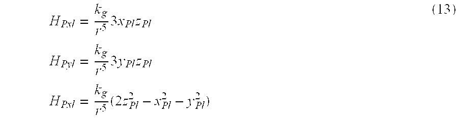
- A magnetic field H w (HPxw, Hpyw, HPzw) whose components have the same directions as the Xw, Yw and Zw axes and which is developed at the point P in the world coordinate system is expressed as follows:

- As shown in FIG. 12, assume that a source coil is placed at a proper position (X g, Yg, Zg) in the three-dimensional space, and that a single-core coil (hereinafter, a sense coil) is placed at a position (Xd, Yd, Zd) on the Y axis. The single-core coil has the same direction as the Y axis and detects a magnetic field generated by the source coil as an electromotive force. A magnetic field Hy developed at the position of the sense coil is expressed based on the formula (14) as follows:

- Furthermore, an electromotive force V y developed at the sense coil is expressed as a formula below that provides the partial differential of the magnetic field Hy with respect to a time t.

- where N 2 denotes the number of windings constituting the sense coil. Moreover, ωImaxcos (ωt+φ) gives a value calculated by differentiating a current Imaxsin(ωt+φ) flowing into the source coil with respect to the time t.
- As shown in FIG. 13, assume that a circle is drawn with the Y axis as a center and that the source coil is moved along the circle. A constant electromotive force is detected at the sense coil all the time. However, the orientation of the sense coil relative to the Y axis remains unchanged.
- Therefore, when a plurality of sense coils is lined on the Y axis, a space in which the source coil exists, that is, the circle with the Y axis as a center can be estimated.
- As shown in FIG. 14, assume that four sense coils are placed on the Y axis and that a coordinate system defined on a plane y determined with the Y axis and the position of the source coil is X′-Y′. An electromotive force V yi developed at each sense coil is expressed as follows:

- where g x and gy denote terms specified with the plane y and the orientation of the source coil. Moreover, xdi and ydi indicate the position of each sense coil in the coordinate system X′-Y′, and xg′ and yg′ indicate the position of the source coil.
- The formula (17) includes four unknowns g x, gy, xg′, and yg′. When at least four sense coils are lined in the same direction along the Y axis, four equations are defined. The position of the source coil in the coordinate system X′-Y′ can be determined by solving the equations.
- Specifically, as shown in FIG. 15, a source coil for generating magnetic fields is placed at a proper position in a three-dimensional space, and four sense coils are placed along the Y axis. A plane y determined with the source coil and four sense coils is regarded as an X′-Y′ plane. The position of the source coil shall be indicated as (x g, yg), and the positions of the sense coils shall be indicated as (Xd0, yd0), (xd1, yd1), (xd2, yd2), and (xd3, yd3) respectively.
- Electromotive forces V y0, Vy1, Vy2, and Vy3 developed at the sense coils Cs0, Cs1, Cs2, and Cs3 are expressed based on the formula (17) as follows:

- Incidentally, k si (i=0, 1, 2, 3) denotes a constant determined with a current flowing into the source coil and the number of windings constituting each sense coil.
- Now, the formulas (19) and (20) are rewritten into a matrix as follows:

- The terms specified with the positions of the sense coils and source coil are rewritten as a matrix A as follows:

- An inverse matrix A −1 of the matrix A is defined according to the Cramer's formula as follows:

- Consequently, g x and gy are expressed as follows:

- The determinant of the inverse matrix A −1 is solved, and gx and gy are assigned to the formulas (18) and (21).

- The formulas (26) and (27) are nonlinear equations having unknowns x g and yg. xq and yg are obtained by solving the two equations according to the Newton's method.
- Assuming that electromotive forces developed at sense coils are V y0′ and Vy3′ respectively and that Vy0 and Vy3 given by the formulas (26) and (27) are estimated values, differences are expressed as follows:
- f 1(X g , Y g)=V y0 −V y0′ (29)
- f 2(X g , Y g)=V y3 −V y3′ (30)
- Assume that the electromotive forces V y0′ and Vy3′ developed at the sense coils are measured accurately and that xg and yg used to calculate the estimated values Vy0 and Vy3 perfectly agree with those indicating the position of the source coil. In this case, the right sides of the formulas (29) and (30) are 0s.
- For estimating the position of the source coil, therefore, x g and yg with which f1=0 and f2=0 are satisfied should be obtained.
- The partial differentials of f 1 and f2 are solved with respect to xg and yg respectively, whereby a Jacobian determinant J is defined as follows:

- An inverse matrix J −1 of the Jacobian determinant J is defined according to the Cramer's formula, and regarded as a matrix C.

- The Newton's method is an iteration of a nonlinear equation f(X)=O and defined as follows:
- X (k+1) =X (k) −ΔX (k)
- A correction value ΔX (k) is determined while being linearly approximated to the solution of f(X) calculated with X(k) specified as X.
- ΔX (k) =J −1(X (k))f(X (k))
- Assuming that proper initial values of x g and yg are xg0 and yg0 respectively, the approximate values of xg and yg, xg1 and yg1, are obtained according to the following formulas:
- x g1 =x g0 −{C 00 f 1(x g0 ,y g0)+C 01 f 2(x g0 ,y g0)} (33)
- y g1 =y g0 −{C 10 f 1(X g0 ,y g0)+C 11 f 2(x g0 ,y g0)} (34)
- x g1 and yg1 are assigned to the formulas (29) and (30). If f1 and f2 are not 0s, xg1 and yg1 are specified as xg0 and yg0 in the formulas (33) and (34). This results in xg2 and yg2 respectively. Thereafter, f1 and f2 are obtained again. This operation is repeated, whereby f1 and f2 are approximated to 0s. Consequently, xg and yg are obtained.
- The Newton's method is adopted in order to solve the nonlinear equations. Alternatively, the least squares method may be adopted.
- The position of a source coil on a plane defined with sense coils and the source coil can be estimated from outputs of the sense coils each having at least four single-core coils lined in the same direction along the same straight line. In other words, a space (circle) in a three-dimensional space in which the source coil exists can be estimated.
- Out of the at least four sense coils lined in the same direction along the same straight line, at least two sense coils are arranged in a space in order to estimate the three-dimensional position of a source coil (as a point of intersection between two circles in the space).
- Each
sense coil 22 k consists of four single-core coils. The largest output among the outputs of the four single-core coils is acquired as a maximum output, and two sense coils whose maximum outputs are the largest are selected. - The three-dimensional position of each source coil is estimated according to the condition for placement of the two selected sense coils, that is, whether the two sense coils are placed mutually orthogonally or parallel.
- In the present embodiment, a point of intersection between two circles in the space is detected. Otherwise, two circumferential points separated by the shortest distance are detected (two circles may not intersect due to a noise or the like).
- To begin with, a procedure of estimating the three-dimensional position of each source coil will be described on the assumption that two selected sense coils are placed orthogonally. As shown in FIG. 16, a source coil is placed at a proper position, and sense coils are lined along the X axis and Y axis alike. Circles C 1 and C2 on which the source coil exists are determined from the outputs of the sense coils.
- Assume that C 1 is a circle lying on a plane x=a1, centered on (a1, 0, 0), and having a radius r1, and that C2 is a circle lying on a plane y=b2, centered on (0, b2, 0), and having a radius r2.
- C 1:(x−a 1)2 +y 2 +z 2 =r 1 2 (35)
- C 2 :x 2+(y−b 2)2 +z 2 =r 2 2 (36)
- As shown in FIG. 17, the coordinates of a point Q descending perpendicularly from any point P(x 1, y1, z1) to the plane y=b2 are (x1, b2, z1).
- A straight line m lying on the plane y=b 2and passing through the point Q and the center (0, b2, 0) of the circle C2 is expressed using a real variable t as follows:
- x=x 1 +tx 1
- y=b 2
- z=z 1 +tz 1 (37)
- When the formula (35) is assigned to the equation (36) of the circle C 2, (x 1 +tx 1)2+(z 1 +tz 1)2 =r 2 2 (38)
- The real variable t is obtained as follows:

- The straight line m and circle C 2 intersect at two points. Herein, t>0 shall be satisfied. When the formula (39) is assigned to the formula (37),

- The formula (40) expresses, as shown in FIG. 17, a point P′ on the circle C 2 nearest the point P.
- If the point P (x 1, y1, z1) lies on the circle C1, x1, y1, and z1 are expressed as follows:
- x1=a1
- y1=r1 cos θ
- z1=r1 sin θ (41)
- The formula (41) is assigned to the formula (40), thus defining the formula (42).

- The square D of the distance between a point on the circle C 1 and a point on the circle C2 is expressed as follows:

- When the formula (43) is differentiated with respect to θ, the following formula is drawn out:

- The condition under which the solution of the formula ( 44) is a 0 is as follows:
- sin θ=0
- However, the two circles shall not intersect at any point, and r 1<a1 and r1<b2, r1<b2, or r2<a1 shall be established. An alternative condition is expressed as follows:

- θ satisfying the formula (45) is provided as follows:

- The coordinates of the points on the circumferences of the circles C 1 and C2 can be derived from the formulas (46), (40) and (41).
- Assuming that the point on the circle C 1 is indicated as (xc1, yc1, zc1) and the point on the circle c2 is indicated as (Xc2, yc2, zc2) the position (xg, yg, zg) of the source coil can be obtained as averages of the coordinates of the points on the circles as follows:

- Consequently, the spatial position of the source coil can be estimated using two sense coils each having four single-core coils lined in the same direction along the same straight line.
- Next, estimation will be described on the assumption that two selected sense coils are placed parallel to each other. As shown in FIG. 19, sense coils are lined parallel in order to estimate the position of a source coil. A circle C 1 determined using the sense coils shall be expressed as follows:
- x=a 1
- y=b 1 +r 1 cos θ
- z=r 1 sin θ (48)
- A circle C 2 shall be expressed as follows:
- x=a 2
- y=b 2+r2 cos φ
- z=r 2 sin φ (49)
- Assume that a point P 1 on the circle C1 is indicated as (x1, y1, z1) and a point on the circle C2 is indicated as (x2, y2, z2). In this case, the condition under which the points on the circles C1 and C2 intersect or approach most closely is provided as follows:
- y1=y2 and z1=z2 (50)
- When the formulas (48) and (49) are assigned to the conditional expression (50), the following formulas are drawn out:
- b 1 +r 1 cos θ=b 2 +r 2 cos θ (51)
- r 1 sino=r 2 sin φ (52)
- When both the sides of the formula (52) are squared,
- r 1 2(1−cos2 θ)=r 2 2(1−cos2 φ)
- When the formula (51) is assigned to this formula and rewritten,

- A point of intersection (a 1=a2) between the circles C1 and C2 or two most closely located points can be determined from the formulas (48) and (53), the formulas (49) and (52), and the formula (53).
- When the two most closely located points on the circles C 1 and C2 are determined, similarly to when the circles intersect, the x coordinates of the points are averaged in order to estimate one x coordinate. Herein, one y coordinate and one z coordinate are determined according to the formula (53).
- Next, a description will be made of coordinates-of-estimated source coil position calculation to be carried out by the
CPU 32 according to the aforesaid method. - As shown in FIG. 1, four sense coils 22 j each having four single-core coils lined in the same direction along the same straight line are incorporated in the
couch 4. Moreover, theprobe 15 in which the source coils 14 i made by concatenating sixteen single-core coils are placed is passed through theforceps channel 12 in theelectronic endoscope 6. - In the shape-of-
endoscope detection system 3, the maximum amplitudes and phases of voltages developed at the sense coils 22 j associated with the source coils 14 i are measured in order to determine the positive or negative polarities of the voltages, which are attained at the maximum amplitudes, according to the phases. The voltages having the polarities are regarded as voltages developed at the sense coils 22 j. - The
CPU 32 initializes the serial numbers of those of the source coils 14 i and sense coils 22 j, which are treated first, at step S32 and step S32. At step S31, i is reset to 0. At step S32, j is reset to 0. - First, the 0-th source coil and 0-th sense coil are selected. Voltages V 00, V01, V02, and V03 developed at the four single-core coils of the 0-th sense coil are acquired at step S33. At step S34, the highest one of the four acquired voltages acquired at step S33 is detected as a maximum voltage Vmax[j].
- At step S 35, it is detected whether the maximum voltages of all sense coils have been detected. If the detection has not been completed, control is passed to step S36 and j is incremented by one. Control is then returned to step S33.
- When step S 35 is completed, control is passed to step S37. The absolute values of the maximum voltages detected at the sense coils are compared with one another. Two sense coils at which the highest maximum voltages are detected are selected.
- At step S 38, the two-dimensional positions (x′g00, y′g00) and (x′g01, y′g01) of the 0-th source coil on planes defined with the 0-th source coil and the two sense coils selected at step S37 are obtained.
- At step S 39, it is judged whether the two sense coils selected at step S37 are intersecting. If they are intersecting, control is passed to step S40 in FIG. 21. Otherwise, control is passed to step S41 in FIG. 21.
- As described in FIG. 21, at step S 40, a circle on which the source coil exists and which is determined with two intersecting sense coils is specified. At step S41, a circle on which the source coil exists and which are determined using two sense coils is determined.
- At step S 42, points most closely located on the circumferences of the two circles determined under the condition for placement of the two sense coils are determined.
- At step S 43, the three-dimensional position (xg0, yg0, zg0) of the 0-th source coil is obtained from the two points determined at step S42. It is detected at step S44 whether the three-dimensional positions (xgi, ygi, zgi) of all the source coils have been obtained. If the three-dimensional positions of all the source coils (xgi, ygi, zgi) have not been obtained, i is incremented at step S45 in FIG. 20. Control is then returned to step S32. The processing is repeated until the three-dimensional positions of all the source coils (xgi, ygi, zgi) have been obtained. The processing is then terminated.
- Consequently, the spatial position of each source coil can be estimated using sense coils each having four single-core coils lined in the same direction along the same straight line.
- In the present embodiment, necessary sense coils are selected based on the absolute values of the maximum voltages detected at the sense coils. Alternatively, the position of each source coil on a plane determined with the four sense coils and the source coil may be estimated, and two sense coils located most closely to the source coil (the radii of circles are smallest) may be detected. The three-dimensional position of the source coil may then be estimated.
- The thus estimated spatial positions of the source coils are updated all the time. Position update control described in FIG. 22 is extended relative to the position of each source coil. Specifically, as described in FIG. 22, assuming that the spatial (three-dimensional) position of the 0-th source coil is indicated with (x 0, y0, z0), the three-dimensional estimated coordinates (x0, y0, z0) are entered at step S51. It is judged at step S52 whether the three-dimensional estimated coordinates (x0, y0, z0) are the initial three-dimensional estimated coordinates calculated through the first coordinates-of-estimated source coil position calculation. If they are not, control is passed to step S53. If they are the initial three-dimensional estimated coordinates, control is passed to step S54.
- If the three-dimensional estimated coordinates (x 0, y0, z0) are the initial three-dimensional estimated coordinates, the three-dimensional estimated coordinates (x0, y0, z0) are stored as the previous three-dimensional estimated coordinates (XB, yB, zB) at step S54. At step S55, the three-dimensional estimated coordinates (x0, y0, z0) are considered to result from coordinates-of-estimated source coil position calculation. The processing is then terminated.
- A description will be made on the assumption that the three-dimensional estimated coordinates are not the initial ones but the ones calculated through the second processing. Even in this case, at step S 51, the three-dimensional estimated coordinates (x0, y0, z0) are entered. It is judged at step S52 whether the three-dimensional estimated coordinates (x0, y0, z0) are the initial three-dimensional estimated coordinates calculated through the first coordinates-of-estimated source coil position calculation. Since they are not the initial three-dimensional estimated coordinates, control is passed to step S53. It is then judged whether the absolute values of differences between the current three-dimensional estimated coordinates (x0, y0, z0) and the previous three-dimensional estimated coordinates (XB, YB, ZB) exceed predetermined variation limits xx, ys, and zs for the x, y, and z coordinates. If the absolute values do not exceed the limits, similarly to the initial three-dimensional estimated coordinates, the three-dimensional estimated coordinates (x0, y0, z0) are stored as the previous ones (xB, YB, ZB). At step S55, the three-dimensional estimated coordinates (x0, y0, z0) are considered to result from coordinates-of-estimated source coil position calculation. The processing is then terminated.
- Moreover, if it is judged at step S 53 that the absolute values of the differences between the current three-dimensional estimated coordinates (x0, y0, z0) and the previous ones (xB, yB, zB) exceed the predetermined variation limits xs, ys, and zx for the x, y, and z coordinates, control is passed to step S56. The previous three-dimensional estimated coordinates (xB, yB, zB) are considered to result from coordinates-of-estimated source coil position calculation. The processing is then terminated.
- As mentioned above, the position of each source coil is updated based on the predetermined variation limits x s, ys, and zs for the x, y, and z coordinates.
- Referring to FIG. 22, a description has been made by taking the 0-th source coil for instance. The same applies to all the source coils.
- Next, a description will be made of shape-of-endoscope detection image display referred to as step S 13 in FIG. 6.
- Shape-of-endoscope detection image display is, as described in FIG. 23, such that data of a model representing the shape of an endoscope is constructed at step S 61 according to the coordinates of the (three-dimensional) position in a space of a source coil resulting from coordinates-of-estimated source coil position calculation. At depiction mode according to which the model representing the shape of the endoscope is depicted based on the model data representing the shape of the endoscope is judged at step S62. If a normal mode is designated, normal-mode processing is carried out at step S63. If an enlargement mode is designated, enlargement-mode processing is carried out at step S64. The processing is then terminated.
- In the normal mode, a model representing the shape of the endoscope like the one shown in FIG. 24 is displayed on the
monitor 25 of the shape-of-endoscope detection system 3. - In the enlargement mode, as shown in FIG. 25, the
operator panel 24 is used to acquire the coordinates of, for example, the left upper and right lower points defining a range to be enlarged at step S71. The range is defined in the model representing the shape of the endoscope and displayed on the monitor 25 (see FIG. 24). It is judged at step S72 whether the coordinates of the left upper and right lower points are the same as each other. If the coordinates are the same, the range of enlargement cannot be determined. Control is therefore returned to step S71. If the coordinates of the selected left upper and right lower points are not the same as each other, control is passed to step S73. - At step S 73, the current model representing the shape of the endoscope is moved so that the center thereof will be aligned with the center of the defined range. At step S74, the defined range is enlarged in conformity with a display window on the
monitor 25. The processing is then terminated. - Consequently, the model representing the shape of the endoscope and displayed as shown in FIG. 24 on the
monitor 25 is enlarged as shown in FIG. 26 and displayed on themonitor 25. - Moreover, an image showing the shape of the endoscope can be displayed by selecting any of models listed below.
- (1) Three-
dimensional model 1 and three-dimensional model 2 - (2) Two-dimensional model
- (3) Twelve-point model
- (4) Linear model
- For depicting the shape of the endoscope using the three-
dimensional model - As described in FIG. 28, at step S 81, surfaces abcd and cdef shown in FIG. 29 are depicted in that order according to the model data representing the shape of the endoscope. At step S82, the surfaces are shaded based on the normal vectors observed at the points (according to a smooth shading method). Consequently, a three-dimensional image showing the shape of the endoscope is displayed.
- Thereafter, at step S 83, it is judged whether tone correction should be carried out in order to improve a sense of three-dimensionality. For the tone correction, the plane of the
monitor 25 is regarded as an XY plane and a depth direction is regarded as the direction of the Z axis. Tone is corrected by assigning proper gray-scale levels to z coordinates. If it is judged that tone correction should be carried out, the tone correction is carried out at step S84. The processing is then terminated. - The tone correction of step S 84 falls into first tone correction and second tone correction. The first tone correction is such that tone is corrected within a range of measurement performed by the shape-of-
endoscope detection system 3. The second tone correction is such that tone is corrected within a domain in which the model representing the shape of the endoscope is present. - The first tone correction is, as described in FIG. 30, such that maximum and minimum values of z coordinates are acquired from a range of measurement at step S 91. Tone is determined from the model data representing the shape of the endoscope at step S92. Colors that can be displayed are selected based on the tone determined at step S93. Consequently, as shown in FIG. 31, the tone is corrected within the range of measurement defined with z coordinates.
- By contrast, the second tone correction is, as described in FIG. 32, such that maximum and minimum values of z coordinates are acquired from a domain in which the model representing the shape of the endoscope is present at step S 95. Tone is determined from the model data representing the shape of the endoscope at step S96. At step S97, colors that can be displayed are selected based on the tone determined at step S97. Consequently, as shown in FIG. 33, the tone is corrected within the domain in which the shape-of-endoscope model is present. In short, the second tone correction ensures finer tone correction for the model representing the shape of the endoscope than the first tone correction.
- When a two-dimensional model is designated in order to display an image of the shape of the endoscope, a circle is drawn with each of the points in a coordinate system indicating points on the source coils as a center at step S 101 in FIG. 34. Note that the circle is always oriented in the direction of a line of sight. It is judged at step S102 whether tone correction should be carried out. If it is judged that tone correction should be carried out, the tone correction is carried out at step S103. The processing is then terminated. Consequently, an image showing the shape of the endoscope like the one shown in FIG. 35 is displayed on the
monitor 25. - Moreover, when the twelve-point model is designated in order to display an image showing the shape of the endoscope, all points in a coordinate system indicating the positions of all the source coils are linked by lines at step S 105 in FIG. 36. A cross x is drawn at all the points at step S106. The processing is then terminated. Consequently, an image showing the shape of the endoscope like the one shown in FIG. 37 is displayed on the
monitor 25. - Furthermore, when the linear model is designated in order to display an image showing the shape of the endoscope, points in a coordinate system indicating the positions of all the source coils are linked by lines at step S 108 in FIG. 38. A tiny blackened square is drawn at all the points at step S109. The processing is then terminated. Consequently, an image representing the shape of the endoscope like the one shown in FIG. 39 is displayed on the
monitor 25. - (Advantage)
- As described so far, according to the present embodiment, sense coils whose outputs permit estimation of the most precise spaces in which a source coil is present are selected from among a plurality of sense coils placed in a three-dimensional space. The three-dimensional position of the source coil is thus estimated. Consequently, the three-dimensional positions of all source coils can be estimated accurately.
- Second Embodiment:
- (Configuration)
- The configuration of the second embodiment are identical to that of the first embodiment. A difference lies in a method of estimating the three-dimensional position of each source coil. The same reference numerals will therefore be assigned to the components identical to those of the first embodiment. The description of the components will be omitted.
- (Operation)
- A circle on which a source coil is present and which is estimated using one sense coil is, as shown in FIG. 15, determined by solving an equation of a circle expressed using each point (x g, yg). The point (xg, yg) satisfies the two nonlinear equations (26) and (27) defined using the coordinates indicating the positions of any of the single-core coils Cs0 to Cs2 and any of the single-core coils Cs1 to Cs3. The point (xg, yg) is drawn out according to the Newton's method.
- When the source coils and sense coils approach to each other, as shown in FIG. 40, a plurality of points of intersection satisfies the equations (26) and (27). One of the points of intersection is selected based on an estimated initial value (x g0, yg0).
- Assuming that the second point of intersection shown in FIG. 40 is selected, a circle on which a source coil is present is determined based on the coordinates of the second point of intersection.
- The determined circle shall be the circle C 1 shown in FIG. 18. The circle C2 is determined using another sense coil. The most closely located points P and P′ on the two circumferences are obtained in order to determine the three-dimensional position of the source coil.
- At this time, if the second point of intersection is correct, the distance between the points P and P′ approaches to a nil. If the second point of intersection is incorrect, the distance between the points P and P′ expands. A pair of sense coils permitting estimation of two circles, points on which are separated by the shortest distance, is selected in order to estimate the three-dimensional position of a source coil.
- FIG. 41 and FIG. 42 are flowcharts describing estimation of the three-dimensional position of a source coil.
- As described in FIG. 41, at steps S 120 and S121, the serial numbers of the source coils 14 i and sense coils 22 j are initialized.
- First, the 0-th source coil and the 0-th sense coil are selected. Voltages V 00, V01, V02, and V03 developed at four single-core coils constituting the 0-th sense coil are acquired at step S122. It is judged at step S123 whether or not all the four voltages acquired at step S122 are 0 V.
- If it is judged at step S 123 that all the voltages are 0 V, a flag associated with the 0-th sense coil is reset to 0 at step S128. At step S129, j is incremented. Control is then returned to step S122. Control is thus passed to handling of the first sense coil.
- If it is judged at step S 123 that all the voltages are not 0 V, the flag associated with the 0-th sense coil is set to 1 at step S124.
- The position (x g00, yg00) of the 0-th source coil on a plane determined with the 0-th sense coil and 0-th source coil is obtained at step S125. A circle on which the source coil is present is estimated at step S126.
- When it is found at step S 127 that handling the 0-th sense coil is completed, control is passed to step S129. At step S129, j is incremented.
- When it is detected at step S 127 that handling all the sense coils in relation to the 0-th source coil is completed, control is passed to step S131 in FIG. 42.
- As described in FIG. 42, sense coils whose associated flags are set to 1 are selected at step S 131. Relative to all the pairs of selected sense coils, most closely located points on two circumferences are detected and the distance between the two points is calculated.
- A pair of sense coils that is found to have the shortest distance between them at step S 131 is selected at step S132. The three-dimensional position of the source coil is estimated using the two selected sense coils.
- It is judged at step S 134 whether the positions of all the source coils have been estimated. If the positions of all the source coils have not been estimated, i is incremented at step S130 in FIG. 41. Control is then returned to step S121. The processing is repeated until the positions of all the source coils have been estimated. When the three-dimensional positions of the sixteen source coils have been determined, the processing is terminated.
- (Advantage)
- From the distance between points on two circles estimated using a pair of sense coils, it can be judged whether the circles have been estimated correctly. Even if the sense coils and source coils approach to each other, the three-dimensional position of each source coil can be estimated correctly.
- Third Embodiment:
- (Configuration)
- The configuration of the third embodiment is identical to that of the first embodiment. A difference lies in a method of estimating the three-dimensional position of a source coil. The same reference numerals will be assigned to components identical to those of the first embodiment. The description of the components will be omitted.
- (Operation)
- According to the present embodiment, it is judged from the conditions, under which two curves intersect, whether a circle estimated using a sense coil consisting of four single-core coils has been determined highly precisely. Two sense coils are selected depending on the judgment in order to estimate the three-dimensional position of each source coil.
- A circle estimated using one sense coil and having a source coil present thereon is determined by drawing out a point (x g, yg), which satisfies two nonlinear equations (26) and (27), according to the Newton's method. The nonlinear equations (26) and (27) are defined using the coordinates indicating of the positions of any of the single-core coils Cs0 to Cs2 and any of the single-core coils Cs1 to Cs3 shown in FIG. 15.
- The partial differentials of V y0 and Vy3 given as the formulas (26) and (27) with respect to xg and yg are expressed as follows:

- Assuming that y g is a function of xg, the tangent vectors of the curves expressed as the formulas (26) and (27) which are observed at the point (xg, yg) are provided as follows:

- Assuming that the normalized vectors of the tangent vectors are given as follows:
- ν′0=(x′ 0 ,y′ 0) (58)
- ν′3=(x′ 3 ,y′ 3) (59)
- an angle θ at which the curves expressed as the formulas (26) and (27) intersect is provided as follows:
- cos θ=x′ 0 x′ 3 +y′ 0 y′ 3 (60)
- As shown in FIG. 43, when the angle θ is small, the point of intersection is susceptible to a noise. For this reason, two sense coils that provide two curves having the angle θ, which approximates to an angle between orthogonal curves, between them are selected in order to estimate the three-dimensional position of a source coil.
- FIG. 44 and FIG. 45 are flowcharts describing estimation of the three-dimensional position of a source coil.
- As described in FIG. 44, the serial numbers of the source coils 14 i and sense coils 22 j are initialized at step S140 and step S141.
- First, the 0-th source coil and the 0-th sense coil are selected. Voltages V 00, V01, V02, and V03 developed at four single-core coils constituting the 0-th sense coil are acquired at step S142. It is judged at step S143 whether or not all the four voltages acquired at step S142 are 0 V.
- If it is found at step S 143 that all the voltages are 0 V, a flag associated with the 0-th sense coil is reset to 0 at step S150. At step S149, j is incremented. Control is then returned to step S142, and the processing is carried out using the first sense coil.
- If it is found at step S 143 that all the voltages are not 0 V, the flag associated with the 0-th sense coil is set to 1 at step S144.
- At step S 145, the position (xg00, yg00) of the 0-th source coil on a plane determined with the 0-th sense coil and 0-th source coil is obtained. The angle θ at which the two curves intersect at the point (xg00, yg00) is calculated at step S146.
- If it is found at step S 147 that the processing using the 0-th sense coil is completed, control is passed to step S149. j is then incremented at step S149.
- If it is found at step S 147 that the processing performed on the 0-th source coil using all the sense coils is completed, control is passed to step S151.
- At step S 151, sense coils whose associated flags are set to 1 are selected. Two out of the sense coils are selected under the condition that the angle θ between intersecting curves determined using the sense coils is approximate to the angle between orthogonal curves.
- As described in FIG. 45, it is checked at step S 152 whether the two sense coils selected at step S151 are orthogonal to each other. If they are orthogonal to each other, control is passed to step S40. Otherwise, control is passed to step S41.
- Steps succeeding step S 40 until the processing is terminated are identical to those described in relation to the first embodiment (see FIG. 20 and FIG. 21).
- (Operation)
- According to the present embodiment, two sense coils unsusceptible to a noise or the like are selected from among a plurality of sense coils each composed of four single-core coils. The three-dimensional position of a source coil can be estimated highly precisely.
- Fourth Embodiment:
- (Configuration)
- The configuration of the fourth embodiment is identical to that of the first embodiment. Differences lie in the number of sense coils and the placement thereof, and a method of estimating the three-dimensional position of a source coil. The same reference numerals will be assigned to the components identical to those of the first embodiment. The description of the components will be omitted.
- (Operation)
- According to the present embodiment, the three-dimensional position of each source coil is not estimated using sense coils each composed of four single-core coils. Instead, a plurality of single-core coils is arranged in a three-dimensional space. The three-dimensional position and orientation of each source coil are estimated from voltages developed at the single-core coils.
- As shown in FIG. 46, one source coil generating magnetic fields is placed with a gradient (g x, gy, gz) at a position (xg, yg, zg) in a three-dimensional space XYZ.

- Magnetic fields H x, Hy, and Hz, or strictly speaking, components of a magnetic field developed at a proper position P(xd, yd, zd) are expressed as follows:
- where k g denotes a constant, and r denotes a distance between the source coil and the point P. The magnetic fields Hx, Hy, and Hz are oriented in the same directions as the X, Y, and Z axes respectively.
- Assuming that single-core coils C x, Cy, and Cz oriented in the same directions as the coordinate axes X, Y, and Z are placed at the point P, voltages Vx, Vy, and Vz developed at the single-core coils Cx, Cy, and Cz are expressed as follows:

- The single-core coil C x oriented in the X-axis direction is a coil having an axis thereof, about which a wire is wound, oriented in the same direction as the X axis. The same applies to the single-core coils Cy and Cz oriented in the same directions as the Y and Z axes respectively.
- Herein, k s denotes a constant determined with the sizes of source coils and sense coils and the number of windings constituting a coil. r denotes a distance between a source coil and sense coil, and is obtained as follows:
- r={square root}{square root over ((x −x g)2+(y d −y g)2+(z d −z g)2)} (63)
- As shown in FIG. 47, according to the present embodiment, a plurality of sense coils that are single-core coils is arranged in a three-dimensional space. More particularly, twelve sense coils including sense coils 101, 102, 103, and 104, sense coils 105, 106, 107, and 108, and sense coils 109, 110, 111, and 112 are incorporated in the
couch 4. The sense coils 101, 102, 103, and 104 whose centers share the first z coordinate are oriented in the same direction as, for example, the X axis. The sense coils 105, 106, 107, and 108 whose centers share the second z coordinate different from the first z coordinate are oriented in the same direction as the Y axis. The sense coils 109, 110, 111, and 112 whose centers share the third z coordinate different from the first and second z coordinates are oriented in the same direction as the Z axis. Since the voltages, positions, and gradients of the twelve sense coils are already known, twelve nonlinear equations in which the position (xg, yg, zg) and gradient (gz, gy, gz) of a source coil are specified as unknowns can be defined based on the formula (62). - The solutions of the twelve nonlinear equations are obtained, that is, the position and gradient of the source coil are obtained through iterative improvement (Gauss-Newton's method).
- Assume that x is regarded as a parameter specifying the position (x g, yg, zg) and gradient (gz, gy, gz) of the source coil and that an initial value of the parameter is x(0).
- A k-th order estimated value x (k) is obtained through iterative improvement. A function V(x) of a model of power induced in a sense coil is expanded as a Taylor' series in the neighborhood of x(k). The linear approximate expression of the function is provided as follows:

- When Vm is regarded as a voltage measured at a sense coil, an observation equation is defined as follows:

- Herein, the equation is no equality but the right side is nearly equal to the left side. This is because Vm contains an error occurring during measurement.
- When the first term in the right side of the formula (65) is transposed to the left side,
- ΔVm (k) ≈A (k) Δx (k) (66)
- Herein, the following relationship is established:
- ΔVm (k) =Vm−V(x (k))=Vm−Vm (k) (67)
- Δx (k) =x−x (k) (68)
-

- where i denotes any of 1 to n and j denotes any of 1 to m. The number of elements constituting one row corresponds to the number of unknowns n, and the number of elements constituting one column corresponds to the number of sense coils m. By rewriting the formula (66), the solution Δx (k) is expressed as follows:
- Δx (k)=(B (k) WA (k))−1 B (k) WΔVm (k) (70)
- where B denotes a transposed matrix of A, and W denotes a matrix serving as a weight.
- An improved estimated value of the parameter is therefore expressed based on the formula (68) as follows:
- x (k+1) =x (k) +ΔX (k) (71)
- When twelve single-core coils (sense coils) are arranged as shown in FIG. 47, a matrix A expressed as the formula (72) below is defined with the positions and gradients of the coils.

- The weight matrix W is expressed as follows:

- Herein, σ i (i=0, 1, - - - , 11) in the weight matrix W denotes a variation in voltage measured at each sense coil. The variation is attributable to an environmental noise or the like.
- Moreover, the k-th AVm is given as follows:

- Consequently, the position and gradient of each source coil are estimated by following step (1) to step (4) described below.
- At step (1), 0 is specified as k. The initial values of the position and gradient of a source coil are specified as (x g, yg, zg)(0) and (gx, gy, gz)(0) respectively. For example, the initial values of the position and gradient are set to the center position in a space in which the position of the source coil is measured, and a gradient vector (0, 0, 1) having the same direction as the Z axis.
- At step (2), the formulas (72), (73), and (74) are solved with the k-th parameter value specified therein.
- At step (3), the magnitude of update Δx (k) for the k-th parameter value is calculated according to the formula (71).
- At step (4), the steps (2) to (4) are repeated until the magnitude of update Δx (k) is minimized.
- According to the present embodiment, sense coils oriented in the X, Y, and Z-axis directions are placed at the same height above the floor. The position of each source coil is estimated in this state. Alternatively, the sense coils may be placed at any positions and oriented in any directions. As long as the positions and gradients of the sense coils are already known, the position of each source coil can be estimated.
- If a space in which source coils are present is limited, the initial value of the position of each source coil is as mentioned previously adopted as the position thereof. Thus, the position and gradient of each source coil can be obtained through iterative improvement. However, if the space is wide, the initial position must be determined according to an appropriate method.
- For example, when sense coils are arranged in two rows and two columns as they are in the first embodiment, the technique described in relation to the first to third embodiments is employed. Specifically, a space (circle) in which each source coil is present is determined using sense coils each composed of four single-core coils. The position of each source coil is estimated using a plurality of sense coils. Thus, the position of each source coil can be estimated highly precisely according to the iterative improvement method.
- When determination of a circle and iterative improvement are performed relative to all the source coils 14 i, the number of calculations is enormous. Determination of a circle and iterative improvement are performed relative to only the leading
source coil 14 a. In relation to the other source coils, since the source coils are continuous, the estimated position of the immediately preceding source coil may be adopted as an initial value, and iterative improvement may be carried out. For estimating the three-dimensional position of the source coil 14 b, the estimated three-dimensional position of thesource coil 14 a is adopted as an initial value, and iterative improvement is carried out. - Since the source coils are continuous, the three-dimensional position of a source coil to be estimated may be predicted from the estimated three-dimensional position of a preceding source coil. Iterative improvement may be carried out using the predicted position as an initial value.
- Assume that the three-dimensional positions of the source coils 14 a and 14 b are expressed as follows:

- The estimated three-dimensional position of the
source coil 14 a is adopted as an initial value used to estimate the three-dimensional position of the source coil 14 b. The positions of the source coil 14 c and subsequent source coils are predicted from the three-dimensional positions of two preceding source coils. - When the source coil 14 c is taken for instance, the position thereof is predicted according to the following formula:

- Moreover, since the present embodiment is used to examine an organ in a body cavity, a temporal variation in the three-dimensional position of a source coil is presumably limited (motions made in the body cavity by the source coils are limited). From this viewpoint, the iterative improvement method may be implemented by employing the previously estimated three-dimensional position as an initial position.
- (Advantage)
- According to the present embodiment, the three-dimensional position and gradient of each source coil are estimated based on outputs of a plurality of sense coils according to the iterative improvement method. The adverse effect of a noise or the like is alleviated and the precision in estimation can be improved.
- Moreover, when the three-dimensional position of each source coil is estimated through iterative improvement, if an initial position is determined according to an appropriate method, the number of calculations can be decreased.
- Fifth Embodiment:
- (Configuration)
- The configuration of the shape-of-endoscope detection system in accordance with the present embodiment is identical to that in accordance with the fourth embodiment. In the present embodiment, only the three-dimensional position of each source coil is estimated.
- (Operation)
- According to the present embodiment, the three-dimensional position of each source coil is not estimated using sense coils each composed of four single-core coils. Similarly to the fourth embodiment, a plurality of single-core coils is placed in a three-dimensional space. The three-dimensional position of each source coil is estimated from voltages developed at the single-core coils.
- Assume that a matrix of electromotive forces developed at the sense coils in the sense coil unit is V, that a matrix having a term in which the three-dimensional positions of a source coil and sense coils are specified is H, and that a term in which the gradient of the source coil is specified is G. In this case, the following relational expression is established:
- V=HG (77)
- A transposed matrix Ht of the matrix H is specified as a multiplicand in both the sides of the formula (77) in order to delete the term in which the gradient of the source coil is specified.
- H t V=H t HG (78)
- When an inverse matrix [H tH]−1 of HtH is specified as a multiplicand in both the sides of the formula (78),
- [H t H] −1 H t V=G (79)
- The formula (79) is assigned to the formula (77), thus defining the following formula devoid of the term in which the gradient of the source coil is specified.
- V=H[H t H] − H t V (80)
- As shown in FIG. 47, according to the present embodiment, a plurality of sense coils that are single-core coils is arranged in a three-dimensional space. More particularly, twelve sense coils including the sense coils 101, 102, 103, and 104, the sense coils 105, 106, 107, and 108, and the sense coils 109, 110, 111, and 112 are incorporated in the
couch 4. The sense coils 101, 102, 103, and 104 whose centers share the first z coordinate are oriented in the same direction as, for example, the X axis. The sense coils 105, 106, 107, and 108 whose centers share the second z coordinate different from the first z coordinate are oriented in the same direction as the Y axis. The sense coils 109, 110, 111, and 112 whose centers share the third z coordinate different from the first and second z coordinates are oriented in the same direction as the Z axis. Since the voltages, positions, and gradients of the twelve sense coils are known, twelve nonlinear equations in which the position (xg, yg, zg) of a source coil is specified as an unknown are defined based on the formula (62). - The solutions of the twelve nonlinear equations are obtained, that is, the position of the source coil is estimated through iterative improvement (Gauss-Newton's method).
- Now, x is regarded as a parameter indicating the position (x g, yg, zg) of the source coil, and the initial value of the parameter shall be x(0).
- The k-th order estimated value, x (k), is obtained through iterative improvement. A function V(x) of a model of power developed at a sense coil is expanded in the neighborhood of x(k) in order to produce a Taylor's series. The linear approximate expression of the function is given as the formula (64) employed in the fourth embodiment.
- Incidentally, the formula (64) contains the term expressing the following partial differential:

- Herein, V(x) in the term expressing partial differential is expressed by specifying a voltage Vm measured at a sense coil as V in the right side of the formula (80).
- V(x)=H[H t H] −1 H t Vm (82)
- At this time, assuming that the voltage Vm is the voltage measured at a sense coil, the observation equation of the voltage Vm is provided as the formula (65) employed in the fourth embodiment. When the first term in the right side of the formula (65) is transposed to the left side, the formula (66) employed in the fourth embodiment ensues.
- The solution Δx (k) is expressed based on the formula (66) as the formula (70) employed in the fourth embodiment.
- Consequently, an improved estimated value of the parameter is provided based on Δx (k)=x−x(k) as the formula (71) employed in the fourth embodiment.
- When twelve single-core coils (sense coils) are arranged as shown in FIG. 47, a matrix A expressed as the formula (83) below is defined with the positions of the coils.

- A matrix of weights W is provided as the formula (73) employed in the fourth embodiment. In the weight matrix W, σ i (i=0, 1, etc., and 11) denotes a variation in voltage measured at each sense coil. The variation is attributable to, for example, an environmental noise.
- Moreover, ΔVm for the k-th parameter values is expressed as the formula (74) employed in the fourth embodiment. The position of each source coil is obtained by following steps (1)′ to (4)′ described below.
- At step (1)′, 0 is specified as k, and the initial value of the position of a source coil is set to (x g, yg, zg)(0) that indicates, for example, the center in a space in which the position of the source coil is measured.
- At step (2)′, the formulas (83), (73), and (74) are solved with the k-th parameter value specified therein.
- At step (3)′, a magnitude of update Δx (k) for the k-th parameter value is calculated according to the formula (71).
- At step (4)′, the steps (2)′ to (4)′ are repeated until the magnitude of update Δx (k) is minimized.
- According to the present embodiment, the sense coils oriented in the same directions as the X, Y, and Z axes are placed at the same height above the floor, and the position of each source coil is estimated. Alternatively, the sense coils may be arranged at any positions and oriented in any directions. Nevertheless, as long as the positions and gradients of the sense coils are known, the position of each source coil can be estimated.
- If a space in which the source coils are present is narrow, the initial value of the position of a source coil may be considered to indicate a proper position, and iterative improvement may then be carried out in order to estimate the position of the source coil. However, if the space is wide, the initial position must be determined according to an appropriate method.
- For example, when sense coils are arranged in two rows and two columns as they are in the first embodiment, the technique described in conjunction with the first to third embodiments should be adopted. Specifically, a space (circle) in which each source coil is present is determined using a plurality of sense coils each composed of four single-core coils. The position of each source coil is estimated using the plurality of sense coils. By performing iterative improvement, the position of each source coil can be estimated highly precisely.
- Moreover, if determination of a circle and iterative improvement were carried out in relation to each of the source coils 14 i, the number of calculations would be enormous. Therefore, determination of a circle and iterative improvement may be carried out in relation to only the leading
source coil 14 a. For the other source coils, since the source coils are continuous, the estimated position of the immediately preceding source coil may be used as an initial value to carry out iterative improvement. Thus, iterative improvement alone may be carried out. For estimating the three-dimensional position of the source coil 14 b, the estimated three-dimensional position of thesource coil 14 a is used as an initial value to carry out iterative improvement. - Since the source coils are continuous, the three-dimensional position of each source coil to be estimated may be predicted from the previously estimated three-dimensional position of a source coil, and iterative improvement may be carried out with the predicted position as an initial value.
- Similarly to the fourth embodiment, the three-dimensional positions of the source coils 14 a and 14 b are expressed as the formula (75) employed in the fourth embodiment. An initial value used to estimate the three-dimensional position of the source coil 14 b is the position of the
source coil 14 a. For the source coil 14 c and subsequent source coils, the position of each source coil is predicted from the three-dimensional positions of two preceding source coils. For example, the three-dimensional position of the source coil 14 c is estimated according to the formula (76) employed in the fourth embodiment. - Moreover, the present embodiment is used for examinations of body cavities. A temporal variation in the three-dimensional position of each source coil is presumably limited (motions made in a body cavity by the source coils are limited). From this viewpoint, the previously estimated three-dimensional position may be adopted as an initial position for performing iterative improvement.
- (Advantage)
- The present embodiment can provide the same advantage as the fourth embodiment. In addition, the relational expression having the term, in which the gradient of a source coil is specified, excluded and having the number of unknowns decreased can be used to estimate the three-dimensional position of each source coil.
- Sixth Embodiment:
- (Configuration)
- The shape-of-
endoscope detection system 3 of the present embodiment has, in addition to the same components as those of the first embodiment, a position memory means in which estimated positions of source coils are recorded time-sequentially. The other components are identical to those of the first embodiment. The present embodiment is different from the first embodiment in a method of estimating the three-dimensional position of each source coil. - (Operation)
- According to the present embodiment, the method described in conjunction with the first to fifth embodiments is employed in estimating the three-dimensional positions of the source coils 14 i. The estimated three-dimensional positions are successively recorded in a position memory means (not shown).
- The current estimated position of each
source coil 14 i is expressed as follows:
- The past estimated position thereof is expressed as follows:
- The current position P′ i,n of each
source coil 14 i is calculated by weighting and adding up estimated positions. - Assume that a weight to be applied to the current estimated position is a, the current position P′ i,n of each source coil is obtained according to the following formula:
- P′ i,n =αP i,n−1+(1−α)P i,n (86)
- Alternatively, intermediate values of x, y, and z coordinates may be extracted from the current position of each source coil and two past estimated positions. The intermediate values may be considered as the x, y, and z coordinates indicating the current position of each source coil (median filter).
- (Advantage)
- According to the present embodiment, uncertainty in the three-dimensional position of each source coil, which is observed when the source coils and sense coils are separated from each other, can be suppressed.
- Seventh Embodiment:
- (Configuration)
- The configuration of the shape-of-
endoscope detection system 3 of the present embodiment is identical to that of the sixth embodiment. A difference lies in a method of estimating the three-dimensional position of each source coil. - (Operation)
- According to the present embodiment, the method described in relation to the first to fifth embodiments is employed in estimating the three-dimensional positions of the source coils 14 i. The estimated positions are successively recorded in a position memory means (not shown).
- The time-sequentially recorded estimated positions of each
source coil 14 i are provided as follows: - P i,0 ,P i,1 ,P i,2, - - - , P i,N (87)
- The predicted positions of each
source coil 14 i are provided as follows: - Q i,0 ,Q i,1 , Q i,2, - - - Q i,N (88)
- Herein, the N-th predicted position shall be a current position.
- The sum of the squares of differences between the estimated positions and predicted positions of each
source coil 14 i is expressed as follows:
- The sum of the squares of differences in displacement between adjoining predicted positions is expressed as follows:

- f i,1 and fi,2 are added up with fi,2 weighted by ω as follows:
- f i =f i,1 +ωf i,2 (91)
- Herein, when the weight ω is small, the position of each
source coil 14 i approaches the estimated position. When the weight ω is large, the position of eachsource coil 14 i approaches the predicted position. - For obtaining the predicted position Q i,j that minimizes fi, the partial differential of the formula fi is calculated with respect to the predicted position Qi,j and a predicted position Qi,j satisfying f′i=0 is obtained.
- The partial differential of f i is calculated with respect to the predicted position Qi,j, and 0 is specified as f′i.
- P=MQ (92)
- The formula (92) is rewritten using the inverse matrix of M as follows:
- Q=M −1 P (93)
- The predicted position is calculated according to the formula (93).
- For example, seven previous three-dimensional estimated positions of each
source coil 14 i are recorded. The formula (94) below is defined based on the formula (92).
- The weight ω is set to a specified value-and the determinant of the inverse matrix of the matrix M is calculated. The predicted positions are then obtained according to the formula (93).
- (Advantage)
- According to the present embodiment, a motion made by each source coil is predicted from the past estimated positions of each source coil. The current position of each source coil is obtained based on the estimated positions and predicted positions. Uncertainty in the three-dimensional position of each source coil observed when the source coils and sense coils are separated from each other can be suppressed. Even when the source coils make motions, the position of each source coil can be determined on a more stable basis than it is according to the technique employed in the fifth embodiment.
- In the subsequent embodiments, the shape of an endoscope is estimated using the estimation algorithm described in relation to the first to seventh embodiments.
- Eighth Embodiment:
- (Configuration)
- According to the present embodiment, as shown in FIG. 48, examinations are conducted through endoscopic observation using an
endoscope system 206 and a shape-of-endoscope detection system 211. Specifically, theendoscope system 206 consists mainly of anendoscope 203, a camera control unit (hereinafter, a CCU) 204, and anobservation monitor 205. Theendoscope 203 is inserted into the body of apatient 202 lying down on acouch 201. TheCCU 204 having a light source device incorporated therein processes a signal representing an endoscopic image and sent from theendoscope 203. An endoscopic view is displayed on theobservation monitor 205. The shape-of-endoscope detection system 211 that is a position detection system consists mainly of, for example, twelve source coils 203(1) to 203(12), acoil unit 208, acontrol unit 209, and amonitor 210. The twelve source coils 203(1) to 203(12) are incorporated in aninsertion unit 207 of theendoscope 203, and generate magnetic fields. Thecoil unit 208 having, for example, sixteen sense coils 208(1) to 208(16) incorporated therein detects the magnetic fields generated by the source coils 203(1) to 203(12). Thecontrol unit 209 processes a signal output from thecoil unit 208. Consequently, the shape of the endoscope is depicted on themonitor 210. - Hereinafter, the source coils 203(1) to 203(12) are represented by source coils 203(g) (g=1 to 12), and the sense coils 208(1) to 208(16) are represented by sense coils 208(h) (h=1 to 16).
- Three
markers 212 each having one source coil incorporated therein are fastened near the anus of thepatient 202, on the left flank thereof, and on the right flank thereof. Thesemarkers 212 are connected to thecontrol unit 209. Aninput unit 213 used to designate a magnification, modify setting, or enter various kinds of data is also connected to thecontrol unit 209. - The
control unit 209 consists, as shown in FIG. 49, of asystem processor 221, adrive circuit 222, adetection circuit 223, and animage production circuit 225. Thesystem processor 221 controls the components of the shape-of-endoscope detection system 211, and carries out position estimation and other arithmetic operations using detection signals sent from the sense coils 208(h) andmarkers 212. Thedrive circuit 222 supplies a driving current to the source coils 203(g), which are incorporated in theinsertion unit 207 of theendoscope 203, and themarkers 212 in response to a control signal sent from thesystem processor 221. The driving current induces alternating gradients in the source coils and markers. Thedetection circuit 223 amplifies magnetic detection currents supplied from the sense coils 208(h) incorporated in thecoil unit 208 and themarkers 212, converts them into digital signals, and then outputs the digital signals to thesystem processor 221. Theimage production circuit 225 outputs the digital data produced by thesystem processor 221 into analog signals, and outputs the analog signals to themonitor 210. The digital data represents the shape of theendoscope 203 and the locations of themarkers 212. Theinput unit 213 is connected to thesystem processor 221. - (Operations)
- Operations exerted by the present embodiment will be described in conjunction with FIG. 50 to FIG. 55.
- The
system processor 221 in thecontrol unit 9 detects, as described in FIG. 50, the positions of the twelve source coils 203(g) incorporated in theendoscope 203 by manipulating digital data that represents magnetic detection currents supplied from the sense coils 208(h) at step S201. - Thereafter, as shown in FIG. 51, similarly to the positions of the source coils 203(g) in the
endoscope 203, the positions of ananus marker 251, aleft marker 252, and aright marker 253 are detected at step S202. Theanus marker 251,left marker 252, andright marker 253 are themarkers 212 fastened near the anus of thepatient 202, on the left flank thereof, and on the right flank thereof. The outer product h of a vector Ml extending from theanus marker 251 to theleft marker 252 by a vector M2 extending from theanus marker 251 to theright marker 252 is calculated (h=M1×M2). - At step S 203, a plane having the vector h as a normal vector is defined as a patient plane on which a patient lies down. The patient plane shifts along with a change in the posture of the
patient 202, because the patient plane is defined using themarkers 212 fastened to thepatient 202. The vector h exhibits angles of rotation α and β relative to the X and Z axes of a coordinate system for detection. - At step S 204, angles of rotation α′ and β′ of the normal vector h, which is determined at step S203, relative to the X′ and Z′ axes of a coordinate system for display are calculated as shown in FIG. 53.
- At step S 205, based on the angles of rotation α′ and β calculated at step S204, coordinate transformation is performed on data representing the detected positions of the twelve source coils 203(g) incorporated in the
endoscope 203 and data representing the detected positions of theanus marker 251,left marker 252, andright marker 253. - At step S 206, due to the coordinate transformation, the previous image of a shape (FIG. 54) is changed to the image (FIG. 55) with the endoscope seen in the direction of the normal on the patient plane.
- (Advantage)
- As mentioned above, according to the present embodiment, data representing a change in the posture of the
patient 202 is removed from position information of each source coil 203(g). The shape of the endoscope is depicted with the relationship thereof relative to a user-designated line of sight held constant. Once a user sets his/her line of sight in an easy-to-see direction, even if the patient 202 changes his/her posture, the direction of the depicted shape of the endoscope remains constant all the time. - Ninth Embodiment:
- (Configuration)
- The system configuration of the ninth embodiment is identical to that of the eighth embodiment. A difference lies in processing performed by the
system processor 221 in thecontrol unit 209. - (Operation)
- According to the present embodiment, as described in FIG. 56, at step S 201, the
system processor 221 in thecontrol unit 209 detects the positions of the twelve source coils 203(g) incorporated in theendoscope 203. At this time, thesystem processor 221 uses digital data of magnetic detection currents supplied from the sense coils 208(h). - Thereafter, similarly to the source coils 203(g) lying in the
endoscope 203, the positions of theanus marker 251,left marketer 252, andright marker 253 are detected at step S202 (see FIG. 51). Theanus marker 251,left marketer 252, andright marker 253 are themarkers 212 fastened near the anus of thepatient 202, on the left flank thereof, and on the right flank thereof. - At step S 207, a domain of sampling 261 shown in FIG. 57 is defined using the three markers of-the
anus marker 251,left marker 252, andright marker 253. - Thereafter, at step S 208, data of the detected position of the
endoscope 203 is sampled from the domain of sampling 261 defined at step S207. - Finally, at step S 209, an
image 203 a showing the shape of the endoscope andimages 212 a showing the markers are produced using the detected position data of theendoscope 203 and the detected position data of the threemarkers 212. The shape image depicted using the detected position data within the domain of sampling is solely displayed as shown in FIG. 58. - (Advantage)
- As mentioned above, according to the present embodiment, the shape of the endoscope is depicted using the detected position data within a domain of sampling defined using at least three source coils (incorporated in the
anus marker 251,left marker 252, and right marker 253). An excessive image based on data outside the user-designated domain can be eliminated. Consequently, the shape of an endoscope dwelling in a region of interest can be identified readily. - Tenth Embodiment:
- (Configuration)
- The tenth embodiment is nearly identical to the eighth embodiment. A difference alone will be described. The same reference numerals will be assigned to the identical components. The description of the components will be omitted.
- As shown in FIG. 59, the outer surface of the observation monitor 205 that is a CRT is covered with an
isolation sheet 205 a made of a non-conducting material such as polyester. The outer side of theisolation sheet 205 a is covered with amagnetic shielding plate 205 b effective in blocking magnetic fields and made of an amorphous alloy or the like. - Similarly, the outer surface of the
monitor 210 that is a CRT is covered with anisolation sheet 210 a made of a non-conducting material such as polyester. The outer side of theisolation sheet 210 a is covered with amagnetic shielding plate 210 b effective in blocking magnetic fields and made of an amorphous alloy or the like. - As shown in FIG. 60. a
detection circuit 223 in thecontrol unit 209 is electrically isolated from amagnetic shielding casing 271 by fourspacers magnetic shielding casing 271. Themagnetic shielding casing 271 is electrically isolated from thecontrol unit 209 by fourspacers control unit 209. - The other components are identical to those of the eighth embodiment.
- (Operation)
- Next, a description will be made of an operation to be exerted by the present embodiment having the foregoing components. While the
insertion unit 207 of theendoscope 203 is inserted into a body cavity, an endoscopic image of the interior of the body cavity is displayed on the observation monitor 205 that is a CRT by means of theCCU 204. Magnetic fields generated by the source coils 203(g) incorporated in theinsertion unit 207 of theendoscope 203 are detected by the sense coils 208(h). Digital data of magnetic detection currents supplied proportionally to the detected magnetic fields is used to detect the positions of the twelve source coils 203(g) incorporated in theendoscope 203. The shape of the endoscope is depicted on themonitor 210 that is a CRT. - At this time, magnetic noises generated by the
observation monitor 205 and monitor 210 that are CRTs are decayed by themagnetic shielding plate 205 b andmagnetic shielding plate 210 b. Moreover, themagnetic shielding plates observation monitor 205 and monitor 210 respectively owing to theisolation sheet 205 a andisolation sheet 210 a respectively. This intensifies the effect of decay attributable to eddy-current losses occurring on themagnetic shielding plate 205 b andmagnetic shielding plate 210 b. - On the other hand, in the
control unit 209, a magnetic noise generated by thedrive circuit 222 for supplying a driving current that induces alternating gradients in the source coils 203(g) is decayed by themagnetic shielding casing 271. Moreover, themagnetic shielding casing 271 is electrically isolated from thecontrol unit 209 anddetection circuit 222 by thespacers spacers magnetic shielding casing 271. - The other operations are identical to those exerted by the eighth embodiment.
- (Advantage)
- According to the present embodiment, magnetic noises generated by the
observation monitor 205 and monitor 210 that are CRTs are decayed by themagnetic shielding plate 205 b andmagnetic shielding plate 210 b respectively. Moreover, themagnetic shielding plate 205 b andmagnetic shielding plate 210 b are electrically isolated from theobservation monitor 205 and monitor 210 by means of theisolation sheet 205 a andisolation sheet 210 a respectively. This intensifies the effect of decaying magnetic fields by utilizing eddy-current losses occurring on themagnetic shielding plate 205 b andmagnetic shielding plate 210 b. The adverse effect of the magnetic noises generated by theobservation monitor 205 and monitor 210 can be suppressed effectively. The shape of an endoscope can be depicted on themonitor 210 in a more stable manner. - Moreover, in the
control unit 209, themagnetic shielding casing 271 decays a magnetic noise generated by the drive circuit 22 for supplying a driving current with which alternating gradients are induced in the source coils 203(g). Moreover, thespacers spacers control unit 209 anddetection circuit 222. This intensifies the effect of decaying magnetic fields by utilizing an eddy-current loss occurring on themagnetic shielding casing 271. The adverse effect of the magnetic noise generated by thedrive circuit 222 can be suppressed effectively. Consequently, the shape of the endoscope can be depicted on themonitor 210 on a more stable basis. - As shown in FIG. 61, the observation monitor 205 may not be a CRT but may be realized with a
liquid crystal display 281. Moreover, the observation monitor 205 may be realized with a plasma display instead of theliquid crystal display 281. Furthermore, themonitor 210 may be realized with a liquid crystal display or plasma display. - The
liquid crystal display 281 is, in principle, characteristic of a little magnetic noise. Compared with the adoption of a CRT, a magnetic noise can be reduced. The magnetic shields may therefore not be employed. - Eleventh Embodiment:
- (Configuration)
- The eleventh embodiment is nearly identical to the eighth embodiment. A difference alone will be described. The same reference numerals will be assigned to the identical components. The description of the components will be omitted.
- As shown in FIG. 62, an
endoscope 203 a of the present embodiment has aninsertion unit 301 that is elongated and flexible, anoperation unit 302 located at the back end of theinsertion unit 301, and a universal cable 303 extending from theoperation unit 302. A connector attached to the end of theuniversal cable 13 is coupled to theCCU 204. - Moreover, the
operation unit 302 has a bendingknob 304. The bendingknob 304 is manipulated, whereby abendable part 306 adjoining the distal part of theinsertion unit 301 can be bent. - Moreover, according to the present embodiment, no source coils are lying through the insertion unit. An inserted
form detection probe 307 is passed through a treatment appliance channel lying along the axis of theinsertion unit 301. Twelve source coils 203(g) are incorporated at predetermined intervals along the axis of the inserted form detection probe (hereinafter, simply, a probe) 307. - The
probe 307 is passed through the treatment appliance channel, and the distal end or back end of the probe is positioned and immobilized. The twelve source coils 304(g) are thus placed along the axis of theinsertion unit 301 at predetermined intervals. - Moreover, four markers 212(1), 212(2), 212(3), and 212(4) (generically, 212(i)) are placed on the body surface of the
patient 202, for example, near the anus and on the left flank and right flank, and on an operator's hand. The markers 212(i) each contain one magnetic generation device (or marker coil) 212 a. - According to the present embodiment, the
probe 307 having the source coils 203(g) incorporated therein is passed through the forceps channel lying through theendoscope 203 a. The source coils 203(g) are thus incorporated in theinsertion unit 301 of theendoscope 203 a. Alternatively, the source coils 203(g) may be incorporated directly in theinsertion unit 301 of theendoscope 203 a. - As shown in FIG. 63, the
control unit 209 of the present embodiment consists of thedrive circuit 222, thedetection circuit 223, and ahost processor 327. Thedrive circuit 222 drives the source coils 203(g) and marker coils 212 a. Thedetection circuit 223 detects signals received by the sense coils 208(h). Thehost processor 327 consists of aCPU 330 realizing thesystem processor 221 for processing signals detected by thedrive circuit 222, and a videosignal generation circuit 344 realizing theimage production circuit 225. - (Operation)
- As shown in FIG. 63, in the
probe 307 lying through theinsertion unit 301 of theendoscope 203 a, the twelve source coils 203(g) for generating magnetic fields are placed at predetermined intervals. The source coils 203(g) are connected to a source coil drive circuit unit 328 for producing twelve driving signals of mutually different radio frequencies. The source coil drive circuit unit 328 is included in thedrive circuit 222. - Moreover, the marker coils 212 a are connected to a marker coil
drive circuit unit 329 for producing four driving signals of mutually different radio frequencies that are different from the radio frequencies of the source coil driving signals. The marker coildrive circuit unit 329 is included in the drive circuit 22. - In the
drive circuit 222 in thecontrol unit 209, the source coil drive circuit unit 328 drives the source coils 203(g) using currents of sine waves of mutually different frequencies serving as driving signals. The marker coildrive circuit unit 329 drives the marker coils 212 a using the currents serving as driving signal. Driving frequencies at which the coils are driven are set based on driving frequency setting data (or driving frequency data) stored in a driving frequency setting data storage means or driving frequency setting data memory means that is not shown. The driving frequency setting data storage means or driving frequency setting data memory means is included in the source coil drive circuit unit 328 and marker coildrive circuit unit 329 alike. - Data of the driving frequencies is stored in the driving frequency storage means (not shown) in the source coil drive circuit unit 328 and marker coil
drive circuit unit 329 via a parallel input/output (PIO)circuit 331 by means of the central processing unit (CPU) 330 in thehost processor 327. TheCPU 330 is responsible for calculations needed to depict the shape of the endoscope. - On the other hand, the sense coils 208(h) are connected to a sense coil signal
amplification circuit unit 337 included in thedetection circuit 223. - The
detection circuit 223 consists of the sense coil signalamplification circuit unit 337, and A/D converters 338(h). After feeble signals detected by the sense coils 208(h) are amplified by the sense coil signalamplification circuit unit 337, the signals are converted into digital data readable by thehost processor 327 by means of the A/D converters 338(h). The digital data is written in a two-port memory 341 over alocal data bus 340 in response to a control signal sent from a control signalgeneration circuit unit 339. - The
CPU 330 reads the digital data written in the two-port memory 341 over aninternal bus 342 in response to a control signal sent from the control signalgeneration circuit unit 339. TheCPU 330 uses amain memory 343 to perform frequency sampling (fast Fourier transform (FFT)) on the digital data. Items of magnetic detection information representing frequency components whose frequencies correspond to the driving frequencies at which the source coils 203(g) and marker coils 212 a are driven are sampled and separated from the other information. The digital data items of the separated magnetic field detection information are used to calculate the coordinates indicating the spatial positions of the source coils 203(g) that are lying through theinsertion unit 301 of theendoscope 203 a and those of the marker coils 212 a. - Moreover, the inserted state of the
insertion unit 301 of theendoscope 203 a is estimated from the data representing the calculated coordinates indicating the positions of the source coils 203(g). Display data based on which the shape of the endoscope is depicted is output to avideo RAM 336. Furthermore, display data based on which the marker coils 212 a are depicted is produced using the data of the calculated coordinates indicating the positions of the marker coils 212 a. The display data is then output to thevideo RAM 336. - The data written in the
video RAM 336 is read using the videosignal generation circuit 344, converted into an analog video signal, and output to themonitor 210. With input of the analog video signal, the inserted form of theinsertion unit 301 of theendoscope 203 a and the positions of the markers are, as shown in FIG. 64, depicted on the display screen of themonitor 210. - (Advantage)
- According to the present embodiment, the positions of the markers are depicted together with the shape of the endoscope. The positional relationship between the insertion unit of the endoscope and a patient's body can therefore be grasped. In particular, the
marker 212 a placed near the anus serves as an important index indicating a border between the interior of a patient's body and the exterior thereof. - Moreover, one out of the plurality of markers is placed on an operator's hand. The position of the operator's hand can be depicted on the
monitor 210. - Twelfth Embodiment:
- (Configuration)
- The configuration of the twelfth embodiment is identical to that of the eleventh embodiment. The twelfth embodiment is characterized by a method of displaying an image on a monitor.
- (Operation)
- As shown in FIG. 65, a symbol is inscribed in each marker itself. For example, a blackened square is inscribed in the marker 212(1), a blackened triangle is inscribed in the marker 212(2), and a blackened star is inscribed in the marker 212(3). The same symbols are drawn in the images of the corresponding markers on the
monitor 210. The other operations are identical to those exerted by the tenth embodiment. - (Advantage)
- Thus, the markers can be associated with the images of the markers on the monitor. This results in an easier-to-see image showing the shape of the endoscope.
- According to the present embodiment, the blackened square, blackened triangle, and blackened star are employed. The symbols are not limited to these ones. Any colors, numerals, or characters can be employed as long as they are discernible on the monitor. Furthermore, a combination of any of the colors, numerals, or characters, for example, colored characters will do.
- Moreover, according to the present embodiment, the markers on the monitor are depicted as circles with the symbols drawn therein. Alternatively, as shown in FIG. 66, an upward triangle, a rightward triangle, and a leftward triangle will do. Specifically, a blackened triangle may be depicted at the position of the anus, a blackened triangle tilted 90° rightward may be depicted at the position of the right flank, and a blackened triangle tilted 90° leftward may be depicted at the position of the left flank. In short, the images of the markers on the monitor may have any shapes. The images of the markers having any shapes may be displayed in combination with the foregoing symbols.
- Thirteenth Embodiment:
- (Configuration)
- The configuration of the thirteenth embodiment is identical to that of the eleventh embodiment. The thirteenth embodiment is characterized in that the position information of markers can be stored.
- (Operation)
- When the marker 212(1) is placed at the anus of the
patient 202, since the anus is unlikely to the abdomen, not planar, there is difficulty in placing the marker 212(1). There is a fear that the marker 212(1) may come off from thepatient 202 during an examination. - As shown in FIG. 67, the marker 212(1) is placed at the anus of the
patient 202 prior to an examination. At this time, the position data of themarker coil 212 a is stored in a control unit 209 a. A storage area may be preserved in themain memory 343 in thehost processor 327 or in a newly included memory. A command instructing storage is issued from theinput unit 213. - After the position data of the marker 212(1) is stored, the marker 212(1) is removed from the
patient 202 and an examination is started. - In addition to the markers 212(2) and 212(3) actually placed on the
patient 202, display data of the marker 212(1) is produced based on the stored position data of themarker coil 212 a. Themarker coil 212 a is depicted together with the shape of the endoscope during the examination. - Moreover, as mentioned in conjunction with the twelfth embodiment, the markers themselves and the images of the markers on the monitor may be associated with one another even in the thirteenth embodiment.
- (Advantage)
- The positional relationship between the insertion unit of the endoscope and the patient's body can be grasped without occurrence of such an incident that the marker 212(1) comes off from the
patient 202 during an examination. - Fourteenth Embodiment:
- (Configuration)
- The form of the fourteenth embodiment is identical to that of the eleventh embodiment. A difference lies in processing to be performed by the
system processor 221. The same reference numerals will be assigned to the identical components. The description of the components will be omitted. - (Operation)
- An operation to be exerted by the present embodiment will be described in conjunction with FIG. 68.
- The
system processor 221 in thecontrol unit 209 detects the positions of the source coils 203(g) in theendoscope 203 a at step S301 in FIG. 69. - Specifically, the
system processor 221 controls thedrive circuit 222, applies a driving signal of an alternating current sequentially to the source coils 203(g) (g=1 to 12) in theendoscope 203. Alternating gradients are therefore generated around the source coils 203(g). The sense coils 208(h) in thecoil unit 208 detect the alternating gradients. Magnetic detection currents supplied from the sense coils are amplified by thedetection circuit 223, and converted into digital data. Thesystem processor 221 acquires the digital data, and detects the positions of the twelve source coils 203(g) incorporated in theendoscope 203 a. - Similarly to the source coils 203(g) in the
endoscope 203 a, the reference position on thepatient 205, or more particularly, the position of themarker 212 locked near the umbilicus of thepatient 205 is detected using the sixteen sense coils 208(h) (step S302). - The
system processor 221 detects the positions of the twelve source coils 203(g) and those of themarkers 212. Consequently, animage 203 a, of the endoscope (animage 301′ of the insertion unit 301) and animage 212′ of the marker are, as shown in FIG. 70, displayed on the shape display monitor 210 via theimage production circuit 225. - Thereafter, display position correction is instructed using the input unit 213 (or an automatic display position correction mode for automatically correcting display positions is designated). The
system processor 221 corrects the coordinates indicating the positions of theendoscope 203 andmarker 212 according to the position of themarker 212 detected at step S303. - In other words, prior to the correction, the shape of the endoscope is depicted as shown in FIG. 69. The coordinates represented by data of twelve detected points in the
endoscope 203 a and data of the detected position of themarker 212 are corrected using offset values with the position information of themarker 212 as a reference. Consequently, themarker 212 is depicted in the center of the shape of the endoscope. The coordinates in the coordinate system for display are corrected accordingly. Consequently, the shape of the endoscope is depicted as shown in FIG. 70. - For example, a display position at which the
marker image 212′ is displayed may be an eccentric position (Xo′-A, Yo′-B, Zo′-C) deviated from the center (Xo′, Yo′, Zo′) of the display surface of theshape display monitor 210. Herein, the eccentric position and the center are defined in the coordinatesystem 350 for display. In this case, the position of themarker image 212′ and the positions of the source coils 203(g) are corrected by subtracting the offset value (A, B, C) from the coordinates (Xo′-A, Yo′-B, Zo′-C) and (Xsg′, Ysg, Zsg′) indicating the positions respectively. Thereafter, themarker image 212′ and others are displayed. Consequently, the image of the shape of the endoscope is, as shown in FIG. 70, displayed near the center of the display surface of the shape display monitor 210 with themarker image 212′ located in the center. - When the shape of the endoscope is, as shown in FIG. 70, depicted near the center of the display surface, a user may, if necessary, designate or modify any magnification using the
input unit 213. Consequently, theimage 203 a′ of the shape of the endoscope and theimage 212′ of the marker are enlarged at the designated magnification according to the data of the detected position of theendoscope 203 a and the data of the detected position of the marker 212 (see FIG. 71) (step S304). - In this case, unless a magnification is instructed to be modified, the previously designated magnification is adopted as a newly designated magnification in order to produce the
endoscope image 203 a, andmarker image 212′. - Finally, the
endoscope image 203 a′ andmarker image 212′ produced at the previous step S304 are, as shown in FIG. 71, displayed on the shape display monitor 210 (step S305). Shape display is then terminated or control is returned to step S301. - (Advantage)
- According to the present embodiment, the
marker 212 is placed at a reference position that should be depicted in the center of a display area on the monitor in which an inserted shape is depicted. Thepatient 202 may be different in body form and body size from a previous patient or a positional deviation of thepatient 202 on theexamination couch 201 may be different from that of the previous patient. Even in this case, the inserted shape can be developed near the center of a display range in the coordinate system for display and thus depicted. - Consequently, even when a magnification is modified, unless the magnification is excessively large, even if the
patient 202 is different in size from the previous one, it can be prevented effectively that the image of an inserted shape comes out of a display area. A user will therefore be freed or relieved from such a nuisance that he/she must re-set the magnification. - When a proper magnification is set initially, even if the
patient 202 is difference in size from another, the magnification need not be modified. Nevertheless, the image of an inserted shape can be displayed at a proper size but not partly come out of the display area. An operator will be free from a nuisance that a magnification must be modified or re-set. This results in a shape-of-endoscope detection system that is user-friendly or offers good maneuverability. - As mentioned above, according to the present embodiment, the display position at which the shape of the endoscope is depicted is corrected by analyzing the position information of the source coils in relation with the position information of the
marker 212. Consequently, the shape of the endoscope is depicted around the center of a display area. The shape of the endoscope can be enlarged by making the most of the display area. Even when thepatient 202 to be examined through endoscopic observation is changed to another, the shape of the endoscope can be depicted with the display position hardly affected. - Unless a user-designated magnification is excessively large, part of an inserted shape will not come out of the display area but the shape of the endoscope can be depicted large in the display area. In other words, when the shape of the endoscope is depicted at a size permitting a user to enjoy easy-to-see viewing, even if an object is different in size or the like from another, the shape of the endoscope can be depicted with any part thereof not coming out of the display area.
- Fifteenth Embodiment:
- (Configuration)
- The fifteenth embodiment is identical to the fourteenth embodiment except that three markers 212(1), 212(2), and 212(3) (hereinafter, generically, 212(i)) are employed.
- The three markers 212(i) each have one source coil incorporated therein. They are fastened, for example, near the anus of the
patient 202, on the right flank thereof, and on the left flank thereof, and connected to thedrive circuit 222 in thecontrol unit 209 over cables. - According to the present embodiment, the three markers 212(i) each have a source coil incorporated therein and are fastened at reference positions on the
patient 202. A correcting means is included for correcting display positions and a magnification according to the detected positions of the source coils incorporated in the three markers 212(i). Position information unaffected by a change in the position of thepatient 202 is retrieved from the position information of the source coils incorporated in the three markers 212(i). In addition, a magnification is set to a value permitting the shape of the endoscope to be depicted in the whole display surface. Consequently, the detected shape of the endoscope is depicted near the center of the display screen, and enlarged by making the most of the display screen. - (Operation)
- Now, an operation to be exerted by the fifteenth embodiment will be described in conjunction with FIG. 72.
- The
system processor 221 in thecontrol unit 209 uses the digital data of magnetic detection currents supplied from the sense coils 208(h) to detect the positions of the twelve source coils 203(g) incorporated in theendoscope 203 a (step S311). - Thereafter, similarly to the source coils 203(g) in the
endoscope 203 a, the reference positions on thepatient 202, or more particularly, the positions of the markers 212(i) are detected as shown in FIG. 73 (step S312). The markers 212(i) are fastened, for example; near the anus, on the left flank, and on the right flank respectively. Maximum and minimum values of x, y, and z coordinates in the coordinate system fordetection 201 a (a coordinate system defined on the couch 201) are retrieved from the coordinates indicating the estimated positions of the three markers (step S313). - The center of the coordinate system for
detection 201 a is detected from the maximum and minimum values of the x, y, and z coordinates retrieved at step S312 (step S314). Moreover, a magnification is set to a value permitting the positions indicated with the maximum and minimum values of the x, y, and z coordinates in the coordinate system fordetection 201 a to define the largest range of depiction on the whole display screen (step S315). - An
image 203 a′ of the endoscope and images 212(i)′ of the markers like the ones shown in FIG. 74 are produced based on the magnification set at step S315, the data of the detected position of theendoscope 203 a, and the data of the detected positions of the markers 212(i). Finally, theendoscope image 203 a′ and marker images 212(i)′ produced at the previous step S316 are, as shown in FIG. 74, displayed on the shape display monitor 210 (step S317). Shape display is then terminated. - (Advantage)
- According to the present embodiment, a magnification is automatically set according to the body form of a patient (body size) in relation to the positions of the three markers 212(i). In addition to the same advantage as that provided by the fourteenth embodiment, the image of the shape of the endoscope can be enlarged at a magnification matched with the patient's body form (body size) by making the most of a display area.
- Sixteenth Embodiment:
- (Configuration)
- The configuration of the sixteenth embodiment of the present invention is identical to that of the fifteenth embodiment. A difference lies in part of processing of an inserted shape.
- The present embodiment includes, in addition to the same components as the fifteenth embodiment, a depiction correcting means for correcting the thickness at which the shape of the endoscope is depicted or the size at which the markers are depicted. The present embodiment is characterized by a facility for enlarging an image of the shape of the endoscope not only in the same manner as in the fifteenth embodiment but also in such a manner that the shape will not be depicted too thickly and the markers will not be depicted too large in size.
- (Operation)
- Next, an operation to be exerted by the sixteenth embodiment will be described in conjunction with FIG. 75. The flowchart of FIG. 75 is identical to that of FIG. 72 until step S 315.
- The
system processor 221 in thecontrol unit 209 uses the digital data of magnetic detection currents supplied from the sense coils 208(h) to detect the positions of the twelve source coils 203(g) incorporated in theendoscope 203 a (step S311). - Similarly to the source coils 203(g) in the
endoscope 203 a, the positions of the markers 212(i) located, as shown in FIG. 73, near the anus of thepatient 202, on the left flank thereof, and on the right flank thereof respectively are detected (step S312). Maximum and minimum values of x, y, and z coordinates in the coordinate system fordetection 201 a are retrieved from the coordinates indicating the estimated positions of the markers (step S313). - The center of the coordinate system is detected based on the maximum and minimum values of the x, y, and z coordinates in the coordinate system which are retrieved at step S 313 (step S314). Furthermore, a magnification is set to a value permitting the positions indicated with the maximum and minimum values of the x, y, and z coordinates in the coordinate system for
detection 201 a, which are retrieved at step S314, to define the largest range of depiction in the whole display screen (step S315). - An image of the
endoscope 203 a produced based on the data of the detected position thereof and images of the three markers 212(i) produced based on the data of the detected positions thereof are enlarged at the magnification set at step S315. Display positions at which theenlarged endoscope image 203 a′ and marker images 212(i)′ are displayed are determined (step S321). At the magnification, as shown in the upper part of FIG. 76, theendoscope image 203 a′ and marker images 212(i)′ are displayed by making the most of the whole display screen. The thickness of theendoscope image 203 a′ or the size of the marker images 212(i)′ may become too large. - The magnification set at step S 315 is multiplied by a certain coefficient, thus calculating a compressive depiction coefficient. The depiction coefficient determines the thickness of an image of the endoscope and the size of images of the markers as shown in the lower part of FIG. 76 (step S322).
- Thereafter, the thickness and size are determined according to the depiction coefficient calculated at step S 322. The
endoscope image 203 a′ and marker images 212(i)′ are produced with the determined thickness and size, and then displayed at the display positions determined at step S321 (step S323). - Finally, the
endoscope image 203 a′ and marker images 212(i)′ produced at step S323 are displayed as shown in the lower part of FIG. 74 (step S324). The processing is then terminated. - (Advantage)
- The present embodiment can provide the same advantage as the fifteenth embodiment. In addition, the thickness at which the shape of the endoscope is depicted and the size at which the markers are depicted are corrected. Therefore, when an image of the shape of the endoscope is enlarged, it will not take place that the thickness of the image of the shape of the endoscope and the size of the images of the markers get too large in conformity with the magnification. The image of the shape of the endoscope and the images of the markers can be displayed with a proper thickness and proper size. The image of the shape of the endoscope can always be enlarged and displayed at a size permitting a user to enjoy easy-to-see viewing.
- Seventeenth Embodiment:
- (Configuration)
- The present embodiment has, in addition to the same components as those of the fourteenth embodiment, a pointing means such as a mouse. A user points out any area on a display screen of which image he/she wants to enlarge. The image within the area is then enlarged.
- (Operation)
- An operation to be exerted by the present embodiment will be described using the foregoing components.
- Magnetic fields generated by applying a driving signal sequentially to the plurality of source coils 203(g) are detected by the sense coils 208(h) in order to obtain the positions of the source coils 203(g). The shape of the endoscope is then depicted on the
shape display monitor 210. - In this case, when the sixteenth embodiment is taken for instance, the
endoscope image 203 a′ and marker images 212(i)′ are displayed on the shape display monitor 210 as shown in the lower part of FIG. 76. When a user wants to enlarge part of theendoscope image 203 a′ displayed on theshape display monitor 210, the user uses the pointing means such as a mouse to point out anarea 291, of which image the user wants to enlarge, as shown in FIG. 77. Thecontrol unit 209 enlarges the image within the area alone and displays it as shown in FIG. 78. - The present embodiment is not limited to the fifteenth embodiment and sixteenth embodiment but can also apply to the fourteenth embodiment.
- Moreover, the present embodiment can also apply to shape-of-endoscope detection systems in accordance with related arts. For example, the marker 212 (as well as the correcting means for correcting a display position by detecting the position of the marker 212) may be excluded from the configuration of the fourteenth embodiment. In this case, a user may use a mouse or the like of the
input unit 213 to designate any area on the display screen of which image the user wants to enlarge. An instruction for instructing enlargement of the image within the area may then be issued. - (Advantage)
- According to the present embodiment, a user designates a portion of an image, which shows the shape of the endoscope and appears on the monitor, which the user wants to enlarge. The designated portion alone, or in other words, the designated area on the display screen is then enlarged and displayed. Consequently, an image within an area which a user wants to scrutinize can be enlarged and observed.
- The other advantages are identical to those provided by the fourteenth to sixteenth embodiments.
- In the fourteenth embodiment, the plurality of source coils 203(g) is incorporated in the
endoscope 203 a. The plurality of sense coils 208(h) is placed at a known position outside theendoscope 203 a. Themarker 212 has a source coil. Alternatively, the plurality of sense coils 208(h) may be arranged in the endoscope at predetermined intervals. The plurality of source coils 203(g) may be placed at the known position outside theendoscope 203 a, and themarker 212 may has a sense coil. - Moreover, for example, in the fourteenth embodiment, display control is extended as described below. Namely, when an inserted form is depicted on the display means by detecting the position of the
marker 212, if the image of the inserted form is enlarged while being positioned near the center of the display means, any part of the enlarged image of the inserted form will not come out of a display area. A means may be included for changing a reference position at which the inserted form is depicted. - For example, the distal part of the
insertion unit 301 is inserted through the anus. In the initial stage of the insertion, the relative position information of the first source coil 203(1), which is located in the extreme distal end of theinsertion unit 301, with respect to a reference position at which themarker 212 is detected is judged. The reference position (position of the marker) is set in the upper part of the display screen. The shape of the distal part of theinsertion unit 301 that is located below the reference position is depicted with emphasis. Thus, the reference position for display (and, if necessary, a magnification) may be varied depending on an actual inserted state (inserted form) that varies with the progress of insertion. - Moreover, for example, the fifteenth embodiment has the facility for automatically setting the size of an image of an inserted form to be displayed on the display means. Alternatively, the size of the image of an inserted form may be designated manually.
- Eighteenth Embodiment:
- (Configuration)
- The eighteenth embodiment is nearly identical to the eleventh embodiment. A difference alone will be described. The same reference numerals will be assigned to the components identical to those of the eleventh embodiment.
- The eleventh embodiment has the configuration including, as shown in FIG. 63, the four markers 212(i) and having the marker coil
drive circuit unit 329 incorporated in thedrive circuit 222 in thecontrol unit 209. The present embodiment is devoid of the four markers 212(i) and marker coildrive circuit unit 329. This is a difference from the eleventh embodiment. - A light guide over which illumination light emanating from a light source in the
CCU 204 is transmitted is, as shown in FIG. 79, lying through theendoscope 203 a of the present embodiment. The transmitted illumination light is emitted through an illumination window (not shown) formed at the distal end of theinsertion unit 301. A patient or the like is thus illuminated. Light reflecting from an illuminated object such as a lesion is converged on animaging device 352 located on the image plane of an objective 351 by means of the objective 351 locked in an observation window adjoining the illumination window. Theimaging device 352 photoelectrically converts a formed optical image. - A video signal processor in the
CCU 204 processes a signal resulting from photoelectric conversion, thus producing a standard video signal. An image is then displayed on themonitor 205 connected to theCCU 204. Moreover, a control signal instructing reading of an image signal from theimaging device 352 is sent from theCCU 204 to a control unit 209 a in the shape-of-endoscope detection system 211. - Moreover, as described in relation to the eleventh embodiment, the
probe 307 is passed through and locked in the forceps channel 354 (see FIG. 79) in theendoscope 203 a. Theforceps channel 354 is also used as a suction channel through which intracorporeal mucus or the like is sucked. When theprobe 307 is passed through and locked in theforceps channel 354, theforceps channel 354 may not be able to be used as the suction channel any longer. - According to the present embodiment, the
probe 307 in which the plurality of source coils 203(g) is placed at predetermined intervals is hollowed as shown in FIG. 80. Moreover, a plurality ofrecesses 307 a is formed in the lateral surface. Consequently, even when theprobe 307 is passed through and locked in theforceps channel 304, the hollowedprobe 307 and recesses 307 a can be used for suction. Theforceps channel 354 can thus be used as the suction channel. - According to the present embodiment, as mentioned above, the
probe 307 having the source coils 203(g) is passed through and locked in theforceps channel 354 of theendoscope 203 a. The source coils 203(g) are thus incorporated in theinsertion unit 301 of theendoscope 203 a. Alternatively, the source coils 203(g) may be incorporated directly in theinsertion unit 301 of theendoscope 203 a. - When the source coils 203(g) are incorporated directly in the
insertion unit 301 of theendoscope 203 a, the plurality of source coils 203(g) may, as shown in FIG. 81, put on the outer circumference of a tube 355, which forms theforceps channel 354, at predetermined intervals. - The other components are identical to those of the eleventh embodiment.
- (Operation)
- An operation to be exerted by the present embodiment will be described below.
- According to the present embodiment, a control signal instructing reading of an image signal from the
imaging device 352 in theendoscope 203 connected to theCCU 204 is sent to the control unit 209 a in the shape-of-endoscope detection system over asignal cable 353. - In response to the control signal sent from the
CCU 204, the control unit 209 a in the shape-of-endoscope detection system 211 instructs the plurality of sense coils 208(h) placed in thecoil unit 208 to detect magnetic fields generated by the plurality of source coils 203(g) in theprobe 307. Theprobe 307 is passed through and locked in theforceps channel 354 in theendoscope 203 a. Detection signals output from the plurality of sense coils 208(h) in thecoil unit 208 are analyzed in order to estimate the three-dimensional positions of the plurality of source coils 203(g) in theprobe 307 passed through and locked in theforceps channel 354. Consequently, the shape of the endoscope is depicted on themonitor 210. - FIG. 82 shows an example of images of the shape of the
insertion unit 301 produced by interpolating the three-dimensional positions of the source coils 203(g) estimated by the shape-of-endoscope detection system 211. - Points Pk (k=0, 1, - - -, n−1) indicate the three-dimensional positions of the source coils 203(g). Herein, k denotes the serial number of each source coil starting with the source coil located at the probe tip.
- FIG. 83 and FIG. 84 show an image produced by projecting the inserted form shown in FIG. 83 on the XY plane. Points Ak(xk, yk) (k=0, 1, - - -, n−1) indicate the positions of the source coils on the XY plane, on which the inserted form is projected, associated with the three-dimensional positions Pk (k=0, 1, - - -, n−1). Vectors Vk (k=0, 1, - - -, n−2) are vectors exhibited by two most distal source coils 203(g) located in the distal part of the probe.
- Overlapping of two vectors is assessed in order to judge a looped inserted form of the endoscope.
- Referring to FIG. 85, a mention will be made of a method of detecting overlapping of, for example, vector V 0 and vector V3. Specifically, a point of intersection (x03, y03) between
straight lines - (1) when x1<x0 and y1<y0
- x1≦x03≦x0 and y1≦y03≦y0
- (2) when x1<x0 and y0<y1
- x1≦x03≦x0 and y0≦y03≦y1
- (3) when x0<x1 and y1<y0
- x0≦x03≦x1 and y1≦y03≦y0
- (4) when x0<x1 and y0<y1
- x0≦x03≦x1 and y0≦y03≦y1
- (5) when x4<x3 and y4<y3
- x4≦x03≦x3 and y4≦y03≦y3
- (6) when x4<x3 and y3<y4
- x4≦x03≦x3 and y3≦y03≦y4
- (7) when x3<x4 and y4<y3
- x3≦x03≦x4 and y4≦y03≦y3
- (8) when x3<x4 and y3<y4
- x3≦x03≦x4 and y3≦y03≦y4 (conditional expression)
- All pairs of vectors are assessed for overlapping. First, the leading vector V 0 is assessed for overlapping relative to vector V2 to vector Vn−1. Thereafter, vector V1 is assessed for overlapping relative to vector V3 to vector Vn−1. This operation is repeated until it is performed on vector Vn−4, whereby all pairs of vectors can be assessed in order to detect overlapping.
- If overlapping of vectors is detected during processing, for example, a warning may be displayed to indicate that looping is observed on the screen of the
monitor 210 on which an inserted form of the endoscope is depicted. Moreover, the shape-of-endoscope detection system 211 may utter a sound to attract a user's attention. - The foregoing processing will be described in conjunction with the flowcharts of FIG. 86 and FIG. 87. As described in FIG. 86, the identification number i of a source coil is initialized at step S 501. A source coil is projected on a projection surface corresponding to the
monitor 210 in order to transform the coordinates indicating the estimated three-dimensional position of the source coil into coordinates indicating a two-dimensional position. The coordinates indicating the two-dimensional position is then recorded at step S502. The identification number of a source coil is incremented by one in order to transform the coordinates indicating the three-dimensional position of the next source coil at step S503. It is judged at step S504 whether the coordinates indicating the three-dimensional positions of all source coils have been transformed. If it is judged that the coordinates indicating the three-dimensional positions of all the source coils have been transformed, control is passed to step S505 in FIG. 87. - As described in FIG. 87, the identification numbers i and j of two vectors Vi and Vj are initialized at steps S 505 and S506 respectively. The equations of straight lines li and lj having the same directions as the vectors Vi and Vj are defined at steps S507 and S508. A point of intersection (xij, yij) between the two straight lines li and lj is determined at step S509. It is judged at step S510 according to discriminants for the equations whether the point of intersection (xij, yij) is present on the two vectors Vi and Vj. If it is judged at step S510 that the point of intersection is present on the two vectors, it means that the two vectors are intersecting. It is therefore judged that looping is observed. A warning is given to a user manipulating the endoscope at step S516. If the point of intersection is not present on the two vectors, it means that the two vectors are not intersecting. Control is then passed to the next step S511.
- At step S 511, the identification number of vector Vj is incremented by one. It is judged at step S512 whether vector Vj is intersecting vector Vi. If it cannot be judged at step S512 whether vector Vj is intersecting vector Vi, control is returned to step S507. If it is judged that vector Vj is intersecting vector Vi, control is passed to step S513.
- At step S 513, the identification number of vector Vi is incremented by one. It is judged at step S514 whether vector Vj has been checked for intersection relative to all vectors Vi. If it is judged that vector Vj has not been checked for intersection relative to all vectors Vi, control is returned to step S506. If it is judged that vector Vj has been checked for intersection relative to all the vectors Vi, the program is terminated.
- According to the present embodiment, a warning is displayed on the
monitor 210 connected to the control unit 209 a in the shape-of-endoscope detection system 211. Alternatively, the warning may be displayed on the image observation monitor 205 connected to theCCU 204. Moreover, theCCU 204 may utter a sound so as to attract a user's attention. - (Advantage)
- As mentioned above, according to the present embodiment, it is possible to help a user recognize that the insertion unit of the endoscope is looping.
- Nineteenth Embodiment:
- (Configuration)
- The nineteenth embodiment is nearly identical to the eighteenth embodiment. A difference alone will be described. The same reference numerals will be assigned to identical components. The description of the components will be omitted.
- The
CCU 204 in the present embodiment consists of, as shown in FIG. 88, asignal processing unit 204 a, afreeze circuit 204 b, amotion estimation circuit 204 c, and acontrol circuit 204 d. Thesignal processing unit 204 a processes an image signal sent from theimaging device 352 in theendoscope 203 a. Thefreeze circuit 204 b outputs an image signal processed by thesignal processing unit 204 a to theimage observation monitor 205, and switches a motion picture and still picture. Themotion estimation circuit 204 c estimates a motion made by the distal part of theinsertion unit 301 according to the three-dimensional position information of the distal part of theinsertion unit 301 sent from the control unit 209 a in the shape-of-endoscope detection system 211 over thesignal cable 353. Thecontrol circuit 204 d controls thefreeze circuit 204 b according to a manipulation performed on a Freeze switch located on theoperation unit 302 of theendoscope 203 a, and the motion made by the distal part of theinsertion unit 301 and estimated by themotion estimation circuit 204 c. - The other components are identical to those of the eighteenth embodiment.
- (Operation)
- An operation to be exerted by the present embodiment having the foregoing components will be described below.
- According to the present embodiment, a control signal instructing reading of an image signal from the
imaging device 352 in theendoscope 203 a connected to theCCU 204 is sent to the control unit 209 a in the shape-of-endoscope detection system 211 over thesignal cable 353. - In response to the control signal sent from the
CCU 204, the control unit 209 a in the shape-of-endoscope detection system 211 uses the plurality of sense coils 208(h) placed in thecoil unit 208 to detect magnetic fields generated by the plurality of source coils 203(g). The plurality of source coils 203(g) is placed in theprobe 307 passed through and locked in theforceps channel 354 in theendoscope 203 a. Detection signals supplied from the plurality of sense coils 208(h) in thecoil unit 208 are analyzed to estimate the three-dimensional positions of the plurality of source coils 203(g) in theprobe 307 passed through and locked in theforceps channel 354. Consequently, the shape of the endoscope is depicted on themonitor 210. - By manipulating the Freeze switch located on the
operation unit 302 of theendoscope 203 a, images to be displayed on the image observation monitor 205 can be switched from a motion picture to a still picture. - As described in relation to the eighteenth embodiment, the plurality of source coils 203(g) is placed in the
probe 307 at predetermined intervals. Theprobe 307 is passed through and locked in theforceps channel 354 in theendoscope 203 a. Consequently, the plurality of source coils 203(g) is placed along theinsertion unit 301 of theendoscope 203 a. The distal source coil 203(1) is, as shown in FIG. 79, located near the distal end of theinsertion unit 301. The shape-of-endoscope detection system 211 can detect the three-dimensional position of the distal end of theinsertion unit 301 using the source coil 203(1). - According to the present embodiment, the control unit 209 a supplies the information of the detected three-dimensional position of the
insertion unit 301 to theCCU 204 over thesignal cable 353. A motion made by the distal part of theinsertion unit 301 is detected based on the three-dimensional position information of the distal part of theinsertion unit 301. Control is then extended to freezing activated using the Freeze switch located on theoperation unit 302 of theendoscope 203 a. - Specifically, as shown in FIG. 89, the three-dimensional position information (xk, yk, zk) of the distal part of the
insertion unit 301 is input from the control unit 209 a to theCCU 204 over thesignal cable 353. At this time, themotion estimation circuit 204 c stores the three-dimensional information (xk, yk, zk) of the distal part of theinsertion unit 301. - Thereafter, the
motion estimation circuit 204 c reads the previously stored three-dimensional position information (xk−1, yk−1, zk−1) at step S522. A magnitude of motion mk made by the distal part of theinsertion unit 301 is calculated based on the three-dimensional position information (xk, yk, zk) stored this time and the previously stored three-dimensional position information (xk−1, yk−1, zk−1) according to the formula (95). - m k={square root}{square root over ((x k−1 −x k)2+(y k−1 −y k)2+(z k−1 −z k)2)}(95)
- At step S 524, the
control circuit 204 d in theCCU 204 judges whether a freeze instruction signal has been input by manipulating the Freeze switch located on theoperation unit 302 of theendoscope 203 a. If the freeze instruction signal has been input, it is judged at step S525 whether the magnitude of motion mk made by theinsertion unit 301, which is calculated by themotion estimation circuit 204 c at step S525, is smaller than a predetermined threshold mth. If the magnitude of motion mk is not smaller than the threshold mth, control is returned to step S524. - When the
control circuit 204 d judges that the magnitude of motion mk made by the distal part of theinsertion unit 301 is smaller than the predetermined threshold mth, thecontrol circuit 204 d controls thefreeze circuit 204 b at step S526. Consequently, an ongoing endoscopic image (motion picture) having been processed by thesignal processing circuit 204 a is displayed in the form of a frozen image (still picture) on theimage observation monitor 205. - (Advantage)
- As mentioned above, according to the present embodiment, a motion made by the
insertion unit 301 of theendoscope 203 a can be estimated accurately. A frozen image devoid of a color mismatch can be displayed. - According to the present embodiment, the plurality of source coils 203(g) is placed in the
probe 307 and theprobe 307 is passed through and locked in theforceps channel 354 in theendoscope 203 a. If the shape of the endoscope need not be depicted, only one sense coil may be embedded directly in the distal part of theinsertion unit 301. The magnitude of motion mk made by the distal part of theinsertion unit 301 may then be calculated using the sense coil in the distal part. Freezing may then be controlled accordingly. - As mentioned above, the three-dimensional positions of the plurality of source coils 203(g) lying through the
probe 307 are estimated for calculating the magnitude of motion mk made by the distal part of theinsertion unit 301. Theprobe 307 is passed through and locked in theforceps channel 354 in theendoscope 203 a. The technique of estimating a motion using a displayed image which is described in, for example, Japanese Examined Patent Publication No. 8-34577 may be adopted in combination with the technique of calculating the magnitude of motion in order to control freezing. - In this case, the
control circuit 204 d references both the magnitude of motion made by the distal part of theinsertion unit 301, which is calculated using the source coils and sense coils according to the present embodiment, and the magnitude of motion calculated using an image according to the Japanese Examined Patent Publication No. 8-34577. If it is judged that both the magnitudes of motion indicate no motion, a frozen image is displayed on theimage observation monitor 205. Moreover, if it is judged that either of the magnitudes of motion indicates a motion, a normal motion picture is displayed on theimage observation monitor 205. - Consequently, a motion made by the distal part of the
insertion unit 301 can be detected accurately. Besides, when an object makes motions, motions shown by images can be detected. A frozen image showing a little motion can be produced. - Twentieth Embodiment:
- (Configuration)
- The twenty-first embodiment has the same configuration as the nineteenth embodiment. The description of the configuration will be omitted.
- (Operation)
- According to the present embodiment, as shown in FIG. 90, a freeze instruction signal is waited at step S 531. When the freeze instruction signal is generated, magnitudes of motions shown by images produced from the time of generation until a predetermined time instant are calculated successively. An image showing the least magnitude of motion is displayed as a frozen image.
- Specifically, if it is found at step S 531 that a freeze instruction signal has been generated, a parameter j is initialized at step S532. A magnitude of motion mk shown by an image Ik that is the k-th input is calculated according to the formula (95) at steps S521, S522, and S523. At step S533, it is judged whether the parameter j is a 0. Since the parameter j is a 0, the calculated magnitude of motion mk is recorded as the least magnitude of motion mmin=mk. The image Ik is then displayed as a frozen image at step S535.
- It is judged at step S 536 whether the parameter j exceeds a predetermined frequency S. Since the parameter j does not exceed the predetermined frequency S, control is passed to step S537. The parameters j and k are incremented by one, and control is returned to step S521. The magnitude of motion mk+1 shown by the next image Ik+1 is calculated at steps S521 to S523. It is judged at step S533 whether the parameter j is a 0. Since the parameter j is a 1, control is passed to step S538. The magnitude of motion mk+1 shown by the image Ik+1 is compared with the least magnitude of motion mmin. If mk+1<mmin, control is passed to step S534. The magnitude of motion mk+1 is recorded as the least magnitude of motion mmin=mk+1. The image Ik+1 is displayed as a frozen image at step S535. By contrast, if mmin<mk+1, the magnitude of motion and frozen image remain unchanged. Control is returned to step S537.
- The above procedure is repeated. If it is judged at step S 536 that the parameter j exceeds the predetermined frequency S (a predetermined time has elapsed), an image showing the least motion among motions detected within the predetermined frequency (predetermined time) is displayed as a frozen image.
- (Advantage)
- As mentioned above, according to the present embodiment, an image showing the least motion among motions detected within the predetermined time can be displayed as a frozen image.
- Twenty-first embodiment:
- (Configuration)
- The configuration of the twenty-first embodiment is nearly identical to that of the eighth embodiment. The
control unit 209 has, as shown in FIG. 91, arecording unit 224 for recording digital data produced by thesystem processor 221 for representing the shape of theendoscope 203 and the positions of themarkers 212. Setting data used to reflect setting parameters in the digital data representing the shape of theendoscope 203 and the positions of themarkers 212 is input from theinput unit 213 to thesystem processor 221. The same reference numerals are assigned to the other identical components. - (Operation)
- An operation to be exerted by the twenty-first embodiment will be described in conjunction with FIG. 92 to FIG. 95.
- As described in FIG. 92, based on digital data representing magnetic detection currents supplied from the sense coils 208(h), the
system processor 221 in thecontrol unit 209 detects the positions of the twelve source coils 203(g) and the positions of themarkers 212 at step S401. The twelve source coils 203(g) are incorporated in theendoscope 203. Themarkers 212 are fastened near the anus of thepatient 202, on the left flank thereof, and on the right flank thereof respectively. - The current setting for a screen structure is acquired as setting parameters at step S 402. If it is found at steps S403 and S404 that neither a recording request nor a reproduction request has been issued, the
image production circuit 225 produces at step S405 a display image according to the setting parameters for the screen structure acquired at step S402. - If it is found at step S 403 that a recording request has been issued, control is passed to step S411 in FIG. 93. Position data of detected positions is recorded in the
recording unit 224 at step S411. The setting for the screen structure is recorded in therecording unit 224 while associated with the position data produced at step S401 in relation to identification numbers or the like. Normal displaying is restarted at step S405 in FIG. 92. - Data recorded in the
recording unit 224 is data composed of, as shown in FIG. 95, a header and a coordinate data division. The header includes a doctor name, a patient identification number, a date of examination, a start time instant of examination, and an end time instant thereof. The coordinate data division includes position data and setting data for a screen structure to be recorded. - If it is found at step S 404 in FIG. 92 that a reproduction request has been issued, control is passed to step S421 in FIG. 94. Position data of detected positions is read from a user-designated record data block in the
recording unit 224 at step S421. Thereafter, the setting data for a screen structure associated with the position data of detected positions read at step S421 is read from therecording unit 224 at step S422. - It is judged at step S 423 whether any parameter must be reflected in the setting data for a screen structure read by a user manipulating the data input unit 226. If any parameter should be reflected, the designated parameter is reflected at step S423 in the current setting data for a screen structure acquired at step S402. Control is then returned to normal displaying of step S405 in FIG. 92. If no parameter should be reflected, step S423 is skipped. Control is then returned to normal displaying of step S405 in FIG. 92.
- (Advantage)
- As mentioned above, according to the present embodiment, the
system processor 221 in thecontrol unit 209 records position data of detected positions and setting parameters for display in therecording unit 224. The position data of detected positions is used to produce an image of a shape to be displayed during an examination under endoscopic observation. Not only the same image as that produced during an examination but also another image of the shape that cannot be seen during the examination can be displayed. - Twenty-second Embodiment:
- (Configuration)
- The system configuration of the twenty-second embodiment is the same as that of the twenty-first embodiment. A difference lies in part of processing performed by the
system processor 221 in thecontrol unit 209. - (Operation)
- As described in FIG. 96, according to the present embodiment, if it is found at step S 403 that no recording request has been issued, the
system processor 221 in thecontrol unit 209 carries out editing request judgment of step S431 instead of reproduction request judgment of step S404 performed according to the twenty-first embodiment. At step S431 of editing request judgment, if no editing request has been issued, a display image is produced at step S405 according to the setting parameters for a screen structure acquired at step S402. - If it is found at step S 431 that an editing request has been issued, control is passed to step S421 in FIG. 97. Steps S421 to S424 are carried out in the same manner as those according to the twenty-first embodiment. Specifically, position data of detected positions is read from a user-designated record data block in the
recording unit 224 at step S421. At step S422, the setting data for a screen structure associated with the position data of detected positions read at step S421 is read from therecording unit 224. - It is judged at step S 423 whether any parameter should be reflected in the read setting data for a screen structure that has been designated by a user. If any parameter should be reflected, the designated parameter is reflected at step S423 in the setting data for a screen structure acquired at step S402. Control is then passed to step S432. If no parameter should be reflected, step S423 is skipped and control is passed to step S432.
- At step S 432, control is passed to step S411 in FIG. 93 described in relation to the twenty-first embodiment. At step S411, position data of positions detected at step S401 is recorded in the
recording unit 224. At step S412, the setting for a screen structure is recorded in therecording unit 224 while associated with the position data acquired at step S401 using identification numbers or the like (see FIG. 92). Control is then returned to normal displaying of step S405 in FIG. 96. If it is found at step S432 in FIG. 97 that no recording request has been issued, control is returned to normal displaying of step S405 in FIG. 96. - (Advantage)
- As mentioned above, the present embodiment provides the same advantage as the twenty-first embodiment. In addition, since a facility for editing record data is included, unnecessary data recorded during an examination can be deleted when some spare time can be taken. Necessary minimum data can be preserved.
- Twenty-Third Embodiment:
- (Configuration)
- The twenty-third embodiment is concerned with a method of arranging the
markers 212 that are extracorporeal markers employed in the eighth embodiment or eleventh embodiment. A difference alone will be described. The same reference numerals will be assigned to the identical components. The description of the components will be omitted. - An object of the present embodiment is to provide an extracorporeal marker fastening device facilitating positioning of extracorporeal markers.
- As shown in FIG. 98, an
extracorporeal marker sheet 523 of the twenty-third embodiment is formed with a sheet made of a fabric that is soft enough to come into close contact with thepatient 202 so as to cover the patient. Marker stowage pockets 522 a, 522 b, and 522 c (serving as a means for positioning and fastening extracorporeal markers so that the extracorporeal markers can be freely mounted or dismounted) are formed at positions on the sheet that coincide with reference positions. Specifically, when thepatient 202 is covered with the sheet, the positions of the marker stowage pockets coincide with the reference positions that are positions near the anus of a patient and on both inferior sides of the ribs.Extracorporeal markers - Moreover, the extracorporeal markers 212 i can be readily taken out of the stowage pockets 522 i. Thereafter, when the extracorporeal markers 212 i are stowed in the stowage pockets 522 i again, the extracorporeal markers can be set at the positions nearly identical to the positions at which the markers used to be set.
- (Operation)
- According to the present embodiment, when the posture of the
patient 202 must be changed greatly in order to continue an examination under an endoscopic observation, the extracorporeal markers 212 i may have to be taken out of the stowage pockets 522 i. Even in this case, the extracorporeal markers 212 i can be re-set at the same reference positions readily. - The size of the stowage pockets is set to a value permitting the extracorporeal markers 212 i stowed in the stowage pockets 522 i to remain nearly immobile in the stowage pockets 522 i. The stowage pockets 522 i may be made of an elastic material such as a rubber that can stretch and contract.
- Moreover, a pressure sensitive adhesive double
coated tape 528 having both sides thereof coated with an adhesive is bonded to a plurality of positions on the lining of theextracorporeal marker sheet 523 including the positions of the linings of the marker stowage pockets 522 a, 522 b, and 522 c. Theextracorporeal marker sheet 523 can therefore be readily mounted or dismounted on or from thepatient 202. - (Advantage)
- According to the twenty-third embodiment having the foregoing components, the
extracorporeal marker sheet 523 can be mounted or fastened onto thepatient 202 owing to the pressure sensitive adhesive double coated tape 328 bonded to the lining of theextracorporeal marker sheet 523. Theextracorporeal marker sheet 523 has the marker stowage pockets 522 a, 522 b, and 522 c formed at predetermined positions thereon. Consequently, the extracorporeal markers 22 i should merely be stowed in the stowage pockets 522 i and can thus be readily fastened at the predetermined positions. - Moreover, the
patient 202 may make motions to change his/her posture. Nevertheless, since the pressure sensitive adhesive doublecoated tape 528 is bonded to the lining of theextracorporeal marker sheet 523 or at least the linings of the stowage pockets 522 i, the extracorporeal markers 212 i will not be deviated from the reference positions on thepatient 202. - Even if a patient changes his/her posture, it is nearly unnecessary to re-set the extracorporeal markers 212 i. The burden an operator must incur can be alleviated.
- Moreover, the extracorporeal markers 212 i may have to be taken out of the stowage pockets 522 i of the
extracorporeal marker sheet 523 in order to allow a patient to change his/her posture largely. Even in this case, the extracorporeal markers 212 i should merely be stowed in the stowage pockets 522 i and can thus be fastened at the predetermined positions again. - Moreover, an
extracorporeal marker sheet 523′ of a variant like the one shown in FIG. 99 may be employed. Theextracorporeal marker sheet 523′ has Velcro tapes 542 i (542 a and 542 c in FIG. 99) attached to the predetermined positions in place of the stowage pockets 522 i. Mates 543 i to the Velcro tapes 542 i are bonded to the even parts of the outer surfaces of the extracorporeal markers 212 i (212 a alone in FIG. 99). - Moreover, a belt-like pressure sensitive adhesive double
coated tape 544 is bonded to the lining of theextracorporeal marker sheet 523′. Theextracorporeal marker sheet 523′ can thus be fastened readily on the outer surface of thepatient 202. - Instead of the pressure sensitive adhesive double
coated tape 544, a belt and buckle that are not shown may be adopted as a means for fastening the sheet on the outer surface of thepatient 202. This variant exerts nearly the same operation as the twenty-third embodiment, and provides nearly the same advantage as it does. - Twenty-Fourth Embodiment:
- The twenty-fourth embodiment of the present invention will be described with reference to FIG. 100. FIG. 100 shows an extracorporeal marker sheet in accordance with the twenty-fourth embodiment.
- An object of the present embodiment is the same as that of the twenty-third embodiment.
- As shown in FIG. 100, an
extracorporeal marker sheet 551 of the twenty-fourth embodiment is realized with a sheet body having marker stowage pockets 522 i. The sheet body is shaped like a running shirt that is long enough to reach the buttocks of thepatient 202. The marker stowage pockets 522 i are located at positions on the sheet body which coincide with the vicinity of the anus of thepatient 202 and both inferior sides of the ribs thereof. The extracorporeal markers 212 i are stowed in the marker stowage pockets 522 i. Consequently, the extracorporeal markers 212 i can be fastened at the positions of the marker stowage pockets. - The present embodiment provides the advantage described below.
- The
patient 202 is asked to wear thesheet 551 having the extracorporeal markers 212 i stowed in the stowage portions that are the predetermined stowage pockets 522 i. Consequently, a user is relieved from a nuisance of positioning the extracorporeal markers 212 i. - The sheet body of the
sheet 551 may be designed to open in the directions of the patient's waist. This obviates the necessity of asking thepatient 202 to wear the sheet. Moreover, the sheet can be mounted on thepatient 202 merely by putting the sheet on the patient from above the patient. - The structure of the (extracorporeal)
markers 212 employed in the aforesaid embodiments will be described below. - FIG. 101 and FIG. 102 are a sectional view and a left front view showing the structure of an
extracorporeal marker 212. The extracorporeal marker 212 (for a shape-of-endoscope detection system) shown in FIG. 101 and FIG. 102 has acable 524 extending from a marker body (contact) 562. Acoupling connector 563 is attached to the end of thecable 524. Thecoupling connector 563 can be freely detachably attached to thecontrol unit 209 included in the shape-of-endoscope detection system 211 of, for example, the eighth embodiment. - A
magnetic coil 564 is incorporated in themarker body 562, and coupled to a signal line, which is not shown, contained in thecable 524. Themarker body 562 has acasing 565 that opens, for example, downward. Themagnetic coil 564 is stowed in the opening of thecasing 565. The opening of thecasing 565 is covered with acasing 566 serving as a lid. - Moreover, a portion of (a signal line contained in) the
cable 524 coupled to themagnetic coil 564, which comes out of themarker body 562, is covered with ananti-breakage member 567. Theanti-breakage member 567 secures themagnetic coil 564 and the proximal part of thecable 524 coupled to themagnetic coil 564. - The
magnetic coil 564 is bonded and fixed to aconcave part 568 in the center of thecasing 565. The perimeter of the magnetic coil is filled with afiller 569 formed with an insulating non-magnetic member (that cannot be magnetized), for example, a silicon rubber. Thefiller 569 may be made of any material other than rubbers. Agroove 571 is bored in a place in thecasing 565 where thecasings O ring 572 is embedded in thegroove 571. - A screwing portion 73 of the
casing 566 is sealed with anO ring 574. Thecasings screw 575, whereby the interiors of thecasings - The
anti-breakage member 567 has aconvex part 576 formed at the end thereof. Theconvex part 576 is engaged withgrooves 577 bored in the edges of thecasings convex part 576 is made larger than the inner diameter of thegroove 577. When thecasings casings anti-breakage member 567 are held watertight. - The inner diameter of the
anti-breakage member 567 is made smaller than the outer diameter of thecable 524 extending from themagnetic coil 564. When thecable 524 is inserted, thecable 524 andanti-breakage member 567 are held watertight. - Moreover, the edges of the
casings contractile tube 578 in order to prevent the casings from parting. Thetube 578 may be any tube having a tightening force, for example, an elastic rubber tube. Members other than themagnetic coil 564 included in themarker body 562 and thecable 524 are all made of a non-magnetic material. - A
grip portion 579 shaped like a dorsal fin is formed on the top of the outer surface of thecasing 565. Thegrip portion 579 shown in FIG. 101 and FIG. 102 may be substituted for agrip portion 580 shaped like a capped pole as shown in FIG. 103. - Moreover,
low grip portions low grip portions - Since the
extracorporeal markers 212 have the foregoing structure, the markers can be held readily by grabbing thegrip portions 579 formed on the outer surfaces of theextracorporeal markers 212. Consequently, theextracorporeal markers 212 can be readily attached or detached to or from the predetermined positions on the body surface or the like. - Moreover, an
extracorporeal marker 581 shaped as shown in FIG. 105 will do. Theextracorporeal marker 581 has gripingconcave parts 583 formed on both sides of amaker body 582. The other structural features are identical to those shown in FIG. 101 and FIG. 102. This extracorporeal marker has the same advantage as the one shown in FIG. 101 and FIG. 102. - An extracorporeal marker having a fastening means for fastening the marker on a body surface will be described below.
- An
extracorporeal marker 585 shown in FIG. 106 is made by applying abonding gel 586 to the bottom of thecasing 566 of themarker body 562 of theextracorporeal marker 212 shown in FIG. 101 and FIG. 102. The bottom of thecasing 566 to which thebonding gel 586 is applied comes into contact with thepatient 202. The other structural features are identical to those shown in FIG. 101 and FIG. 102. - Owing to the structure, the
extracorporeal marker 585 can be readily fastened on a body surface. A nuisance of a time-consuming tedious inspection can be alleviated. - Moreover, a pressure sensitive adhesive double
coated tape 587 may be, as shown in FIG. 107, attached to the bottom of thecasing 566. In this case, a bonding and fastening means is placed on a contact surface of anextracorporeal marker 585′ to be brought into contact with a body surface. The extracorporeal marker can therefore be readily fastened on a body surface. - Furthermore, the structure shown in FIG. 108 or FIG. 109 will do.
- An extracorporeal marker 591 shown in FIG. 108 is made by boring an opening 592 in the
grip portion 579 of themarker body 572 of theextracorporeal marker 212 shown in, for example, FIG. 99. A belt 595 is inserted into the opening 592. The belt 595 has a jut 593 at one end thereof and has a plurality of holes 594, into which thejut 583 is fitted, bored at the other end thereof. - The belt 595 is long enough to be wound about the body of the
patient 202. The belt 595 is wound about thepatient 202 with the jut 593 fitted into any hole 594. The other structural features are identical to those shown in FIG. 101 and FIG. 102. - Like an extracorporeal marker 591′ of a variant shown in FIG. 109, Velcro tapes 596 a and 596 b may be attached to the ends of the belt 595 and joined for fastening the extracorporeal marker 591′.
- A buckle that is not shown may be employed.
- The advantage provided by the extracorporeal marker 591 or 591′ shown in FIG. 108 or FIG. 109 is substantially identical to that provided by the one shown in FIG. 106 or FIG. 107.
- When the extracorporeal marker 591′ has a low grip portion, a jut may be formed in order to prevent the Velcro tapes to be mismated.
- According to the present invention, it is apparent that a wide range of embodiments can be constructed based on the invention without a departure from the spirit and scope of the invention. The present invention will be limited by the appended claims but not be restricted by any specific embodiments.
Claims (43)
1. A shape-of-endoscope detection system, comprising:
a first coil means to be inserted into a subject;
a second coil means placed at a predetermined position;
a transmitting and receiving means for permitting transmission and reception of a first magnetic signal between said first coil means and second coil means, and transmission and reception of a second magnetic signal between said third coil means and second coil means; and
an arithmetic means for calculating first position information representing the position of said first coil means relative to said second coil means according to a first detection signal resulting from the transmission and reception of said first magnetic signal, and calculating second position information representing the position of said third coil means relative to said second coil means according to a second detection signal resulting from the transmission and reception of said second magnetic signal.
2. A shape-of-endoscope detection system according to claim 1 , wherein said first coil means consists of a plurality of coils.
3. A shape-of-endoscope detection system according to claim 2 , wherein said plurality of coils is incorporated in an insertion unit of an endoscope to be inserted into said subject.
4. A shape-of-endoscope detection system according to claim 3 , wherein said plurality of coils is hollowed.
5. A shape-of-endoscope detection system according to claim 1 , wherein said second coil means includes at least: a first magnetic detection unit made by arranging first, second, third, and fourth uniaxial origination coils along the same straight line while orienting them in the same direction; and a second magnetic detection unit made by arranging fifth, sixth, seventh, and eighth uniaxial origination coils along the same straight line, which is not parallel to the straight line along which said first, second, third, and fourth uniaxial origination coils of said first magnetic detection unit are arranged, while orienting them in the same direction.
6. A shape-of-endoscope detection system according to claim 1 , wherein said second coil means includes at least: a first magnetic detection unit made by arranging first, second, third, and fourth uniaxial origination coils along the first straight line while orienting them in the same direction; a second magnetic detection unit made by arranging fifth, sixth, seventh, and eighth uniaxial origination coils along the second straight line parallel to said first straight line while orienting them in the same direction; a third magnetic detection unit made by arranging ninth, tenth, eleventh, and twelfth uniaxial origination coils along the third straight line not parallel to said first straight line while orienting them in the same direction; and a fourth magnetic detection unit made by arranging thirteenth, fourteenth, fifteenth, and sixteenth uniaxial origination coils along the fourth straight line parallel to said third straight line while orienting them in the same direction.
7. A shape-of-endoscope detection system according to claim 1 , wherein said second coil means consists of a plurality of sense coils each having four single-core coils arranged in the same direction along the same straight line, and at least one pair of sense coils is placed not to be parallel to the other sense coils.
8. A shape-of-endoscope detection system according to claim 7 , wherein said arithmetic means includes a distance calculating means for calculating a distance to said first coil means or third coil means with the line of sense coils as an axis.
9. A shape-of-endoscope detection system according to claim 7 , wherein said arithmetic means includes a circular domain specifying means for specifying a circular domain with the line of sense coils as an axis.
10. A shape-of-endoscope detection system according to claim 7 , wherein said arithmetic means includes a sampling means for acquiring as a maximum output the largest output among outputs of said single-core coils constituting each sense coil and sampling said sense coils in descending order of the maximum output; and a space estimating means for-estimating a space, in which said first coil means or third coil means is present, using a sense coil sampled by said sampling means.
11. A shape-of-endoscope detection system according to claim 1 , further comprising a display control means for depicting on a display means position information of said first coil means with a position, at which said third coil means is placed, as a reference according to said first position information and second position information calculated by said arithmetic means.
12. A shape-of-endoscope detection system according to claim 1 , wherein said third coil means consists of a plurality of coils which can be placed at predetermined positions on said subject so that the coils will define a predetermined plane, further comprising a display control means for depicting on a display means position information of said first coil means with said predetermined plane defined by said third coil means as a reference according to said first position information and second position information calculated by said arithmetic means.
13. A shape-of-endoscope detection system according to claim 1 , further comprising a display control means for depicting on a display means position information of said first coil means according to said first position information, and for depicting on said display means position information of said third coil means as marker information, which is different from position information of said first coil means, according to said second position information.
14. A shape-of-endoscope detection system according to claim 13 , wherein said display means depicts the position of said third coil means while being interlocked with an identifying means for identifying said third coil means.
15. A shape-of-endoscope detection system according to claim 13 , wherein said display control means records the position of said third coil means and depicts it on said display means.
16. A shape-of-endoscope detection system according to claim 1 , further comprising a display means for depicting information relevant to said first position information or second position information according to the results of an arithmetic operation performed by said arithmetic means; and a magnetic shield means, located on the surface of said display means, for shield a magnetic field generated by said display means.
17. A shape-of-endoscope detection system according to claim 1 , further comprising a display means for depicting information relevant to said first position information or second position information according to the results of an arithmetic operation performed by said arithmetic means; an isolating means, located on the surface of said display means, for electrically isolating said surface; and a magnetic shield means, located on the surface of said isolating means while isolated from said display means, for shield a magnetic field generated by said display means.
18. A shape-of-endoscope detection system according to claim 3 , wherein an imaging means for imaging an object in said subject is incorporated in the distal part of said insertion unit of said endoscope, further comprising an endoscopic image display means for displaying an image of said object in said subject according to an output signal of said imaging means; a magnetic shield means, located on the surface of said endoscopic image display means, for shield a magnetic field generated by said endoscopic image display means.
19. A shape-of-endoscope detection system according to claim 3 , wherein an imaging means for imaging an object in said subject is incorporated in the distal part of said insertion unit of said endoscope, further comprising an endoscopic image display means for displaying an image of said object in said subject according to an output signal of said imaging means; an isolating means, located on the surface of said endoscopic image display means, for electrically isolating said surface; and a magnetic shield means, located on the surface of said isolating means while isolated from said endoscopic image display means, for shield a magnetic field generated by said endoscopic image display means.
20. A shape-of-endoscope detection system according to claim 3 , wherein an imaging means for imaging an object in said subject is incorporated in the distal part of said insertion unit of said endoscope, further comprising an endoscopic image display means for displaying an image of said object in said subject according to an output signal of said imaging means; a first magnetic shield means, located on the surface of said endoscopic image display means, for shield a magnetic field generated by said endoscopic image display means; a relative position information display means for depicting information relevant to said first position information or second position information according to the results of an arithmetic operation performed by said arithmetic means; and a second magnetic shield means, located on the surface of said relative position information display means, for shield a magnetic field generated by said relative position information display means.
21. A shape-of-endoscope detection system according to claim 3 , wherein an imaging means for imaging an object in said subject is incorporated in the distal part of said insertion unit of said endoscope, further comprising an endoscopic image display means for displaying an image of said object in said subject according to an output signal of said imaging means; a first-isolating means, located on the surface of said endoscopic image display means, for electrically isolating said surface; a first magnetic shield means, located on the surface of said first isolating means while isolated from said endoscopic image display means, for shield a magnetic field generated by said endoscopic image display means; a relative position information display means for depicting information relevant to said first position information or second position information according to the results of an arithmetic operation performed by said arithmetic means; a second isolating means, located on the surface of said relative position display means, for electrically isolating said surface; and a second magnetic shield means, located on the surface of said isolating means while isolated from said relative position information display means, for shield a magnetic field generated by said relative position information generating means.
22. A shape-of-endoscope detection system according to claim 3 , further comprising a model switching means for instructing switching of models representing an inserted form to be depicted on said display means.
23. A shape-of-endoscope detection system according to claim 1 , further comprising a position information correcting means for correcting said first position information with said second position information calculated by said arithmetic means as a reference; a display control means for displaying on a display means a likeness of an inserted form of said insertion unit of said endoscope according to corrected position information provided by said position information correcting means; and an enlargement instructing means for instructing enlargement of the likeness of the inserted form to be displayed on said display means.
24. A shape-of-endoscope detection system according to claim 1 , further comprising a position information correcting means for correcting said first position information according to said second position information calculated by said arithmetic means; and a display control means for depicting on a display means position information of said first coil means according to corrected position information provided by said position information correcting means.
25. A shape-of-endoscope detection system according to claim 1 , further comprising a position information correcting means for correcting said first position information with said second position information calculated by said arithmetic means as a reference; and a display control means for depicting on a display means position information of said first coil means according to corrected position information provided by said position information correcting means, and for controlling enlargement or reduction of a representation of position information of said first coil means to be displayed on said display means with said second position information as a reference.
26. A shape-of-endoscope detection system according to claim 1 , further comprising a position information correcting means for correcting said first position information with said second position information calculated by said arithmetic means as a reference; and a display control means for displaying a likeness of an inserted form of said insertion unit of said endoscope according to corrected position information provided by said position information correcting means, and for controlling enlargement and reduction of the likeness image of the inserted form of said insertion unit of said endoscope to be displayed on said display means with said position information as a reference.
27. A shape-of-endoscope detection system according to claim 1 , wherein said arithmetic means outputs the results of an arithmetic operation as coordinate data, and includes a recording means in which said coordinate data can be recorded continuously, and a display control means for depicting on a display means said first position information or second position information according to said coordinate data output from said arithmetic means and said coordinate data recorded in said recording means.
28. A shape-of-endoscope detection system according to claim 27 , wherein said display control means records in said recording means predetermined parameters, based on which said plurality of coils constituting said first coil means is depicted on said display means, together with said position information.
29. A shape-of-endoscope detection system according to claim 28 , further comprising a data input means used to input setting data to be reflected in said parameters.
30. A shape-of-endoscope detection system according to claim 1 , further comprising an alarming means for sounding an alarm according to the results of an arithmetic operation performed by said arithmetic means.
31. A shape-of-endoscope detection system according to claim 3 , wherein said arithmetic means detects looping of said insertion unit of said endoscope and includes an alarming means for sounding an alarm according to the results of looping detection performed by said arithmetic means.
32. A shape-of-endoscope detection system according to claim 3 , further comprising an imaging means, incorporated in the distal part of said insertion unit of said endoscope, for imaging an object in said subject; and a freezing means for freezing an image projected by said imaging means, wherein said arithmetic means includes a motion estimating means for estimating a motion made by the distal part of said insertion unit of said endoscope according to the three-dimensional position of a coil located in the distal part of said insertion unit of said endoscope; and a freezing control means, activated in response to a freeze instruction issued to said freezing means, for controlling said freezing means according to the results of motion estimation performed by said motion estimating means.
33. A shape-of-endoscope detection system according to claim 32 , wherein said motion estimating means has a magnitude-of-motion calculating means for calculating a magnitude of motion from the three-dimensional positions of a coil located near the distal end of said insertion unit which are estimated at different time instants.
34. A shape-of-endoscope detection system according to claim 32 , wherein said freezing control means controls said freezing means so as to freeze an image when a magnitude of motion estimated by said motion estimating means is smaller than a predetermined threshold.
35. A shape-of-endoscope detection system according to claim 32 , wherein said freezing control means controls said freezing means so as to freeze an image showing the least motion among motions estimated by said motion estimating means within a predetermined time interval.
36. A shape-of-endoscope detection system according to claim 32 , wherein said arithmetic means obtains the positions in a three-dimensional space of said plurality of coils while being interlocked with said imaging means.
37. A shape-of-endoscope detection system according to claim 3 , further comprising an imaging means, incorporated in the distal part of said insertion unit of said endoscope, for imaging an object in said subject; a first motion estimating means for estimating a motion shown by an image using an image projected by said imaging means; and a freezing means for freezing an image projected by said imaging means, wherein said arithmetic means includes a second motion estimating means for estimating a motion made by the distal part of said insertion unit of said endoscope according to the three-dimensional position of a coil located in the distal part of said insertion unit of said endoscope; a freezing control means, activated in response to a freeze instruction issued to said freezing means, for controlling said freezing means according to the results of first motion estimation and second motion estimation performed by said first motion estimating means and second motion estimating means respectively.
38. A shape-of-endoscope detection system according to claim 1 , further comprising an extracorporeal marker fastening device for a shape-of-endoscope detection system consisting of a sheet-like member mounted to cover a patient who undergoes an examination under endoscopic observation, and a fastening means for fastening said third coil means at a proper position on said sheet-like member so that said third coil means can be unfastened freely.
39. A shape-of-endoscope detection system according to claim 38 , wherein said fastening means is realized with pocket-like stowage members.
40. A shape-of-endoscope detection system according to claim 38 , wherein said fastening means is realized with Velcro tapes.
41. A shape-of-endoscope detection system according to claim 38 , wherein said extracorporeal marker fastening device for a shape-of-endoscope detection system has a means for mounting or dismounting said extracorporeal marker fastening device to or from a patient.
42. A shape-of-endoscope detection system according to claim 1 , wherein said third coil means consists of a connection unit for connecting said third coil means to said arithmetic means, a coil body having a magnetic coil incorporated therein, and a cable linking said connection unit and coil body, and has a gripping irregular part formed on the outer surface of said coil body.
43. A shape-of-endoscope detection system according to claim 42 , wherein said coil body has a fastening means for fastening said coil body on a body surface.
Priority Applications (1)
| Application Number | Priority Date | Filing Date | Title |
|---|---|---|---|
| US10/199,889 US6773394B2 (en) | 1998-09-03 | 2002-07-17 | System for detecting the shape of an endoscope using source coils and sense coils |
Applications Claiming Priority (18)
| Application Number | Priority Date | Filing Date | Title |
|---|---|---|---|
| JP10-249906 | 1998-09-03 | ||
| JP24990698A JP3548430B2 (en) | 1998-09-03 | 1998-09-03 | Endoscope shape detector |
| JP10-249909 | 1998-09-03 | ||
| JP10249909A JP2000079129A (en) | 1998-09-03 | 1998-09-03 | Extracorporeal marker fixing device for endscope-shaped detector |
| JP25143498A JP3397299B2 (en) | 1998-09-04 | 1998-09-04 | Position detection device |
| JP10-251434 | 1998-09-04 | ||
| JP10-251436 | 1998-09-04 | ||
| JP10-251433 | 1998-09-04 | ||
| JP10251436A JP2000081303A (en) | 1998-09-04 | 1998-09-04 | Position detector |
| JP25143398A JP3392358B2 (en) | 1998-09-04 | 1998-09-04 | Position detection device |
| JP10272037A JP2000093387A (en) | 1998-09-25 | 1998-09-25 | Magnetic field detector |
| JP10-272037 | 1998-09-25 | ||
| JP10-315024 | 1998-11-05 | ||
| JP31502498A JP3236565B2 (en) | 1998-03-18 | 1998-11-05 | Position estimation device |
| JP10359668A JP2000175861A (en) | 1998-12-17 | 1998-12-17 | Endoscope shape detecting device |
| JP10-359668 | 1998-12-17 | ||
| US09/387,859 US6511417B1 (en) | 1998-09-03 | 1999-09-01 | System for detecting the shape of an endoscope using source coils and sense coils |
| US10/199,889 US6773394B2 (en) | 1998-09-03 | 2002-07-17 | System for detecting the shape of an endoscope using source coils and sense coils |
Related Parent Applications (1)
| Application Number | Title | Priority Date | Filing Date |
|---|---|---|---|
| US09/387,859 Continuation US6511417B1 (en) | 1998-09-03 | 1999-09-01 | System for detecting the shape of an endoscope using source coils and sense coils |
Publications (2)
| Publication Number | Publication Date |
|---|---|
| US20030055317A1 true US20030055317A1 (en) | 2003-03-20 |
| US6773394B2 US6773394B2 (en) | 2004-08-10 |
Family
ID=27573539
Family Applications (2)
| Application Number | Title | Priority Date | Filing Date |
|---|---|---|---|
| US09/387,859 Expired - Lifetime US6511417B1 (en) | 1998-09-03 | 1999-09-01 | System for detecting the shape of an endoscope using source coils and sense coils |
| US10/199,889 Expired - Lifetime US6773394B2 (en) | 1998-09-03 | 2002-07-17 | System for detecting the shape of an endoscope using source coils and sense coils |
Family Applications Before (1)
| Application Number | Title | Priority Date | Filing Date |
|---|---|---|---|
| US09/387,859 Expired - Lifetime US6511417B1 (en) | 1998-09-03 | 1999-09-01 | System for detecting the shape of an endoscope using source coils and sense coils |
Country Status (1)
| Country | Link |
|---|---|
| US (2) | US6511417B1 (en) |
Cited By (43)
| Publication number | Priority date | Publication date | Assignee | Title |
|---|---|---|---|---|
| US20040172292A1 (en) * | 2002-11-21 | 2004-09-02 | Canon Kabushiki Kaisha | Medical image handling system and method |
| US20050228221A1 (en) * | 2002-10-29 | 2005-10-13 | Olympus Corporation | Endoscope information processor and processing method |
| EP1632168A1 (en) * | 2003-08-22 | 2006-03-08 | Olympus Corporation | Device for detecting shape of endoscope |
| WO2005058137A3 (en) * | 2003-12-12 | 2006-05-11 | Univ Washington | Catheterscope 3d guidance and interface system |
| US20070049797A1 (en) * | 2004-03-19 | 2007-03-01 | Olympus Corporation | Double-balloon endoscope system |
| EP1810608A1 (en) * | 2004-11-10 | 2007-07-25 | Olympus Corporation | Endoscope shape determining apparatus |
| US20070219410A1 (en) * | 2004-11-15 | 2007-09-20 | Olympus Medical Systems Corp. | Endoscope shape detection device |
| US20070299309A1 (en) * | 2005-02-28 | 2007-12-27 | University Of Washington | Monitoring disposition of tethered capsule endoscope in esophagus |
| US20080009669A1 (en) * | 2005-01-19 | 2008-01-10 | Olympus Corporation | Electronic endoscope apparatus and image processing device |
| US20080009714A1 (en) * | 2006-06-12 | 2008-01-10 | Olympus Medical Systems Corp. | Endoscope insertion shape detecting device |
| US20080024599A1 (en) * | 2004-11-29 | 2008-01-31 | Katsumi Hirakawa | Image Display Apparatus |
| US20080058629A1 (en) * | 2006-08-21 | 2008-03-06 | University Of Washington | Optical fiber scope with both non-resonant illumination and resonant collection/imaging for multiple modes of operation |
| US20080071170A1 (en) * | 2004-09-13 | 2008-03-20 | The Regents Of The University Of California | Fluoroscopy-Free Guidewire Systems and Methods |
| US20080132834A1 (en) * | 2006-12-04 | 2008-06-05 | University Of Washington | Flexible endoscope tip bending mechanism using optical fibers as tension members |
| US20080221388A1 (en) * | 2007-03-09 | 2008-09-11 | University Of Washington | Side viewing optical fiber endoscope |
| US20080243030A1 (en) * | 2007-04-02 | 2008-10-02 | University Of Washington | Multifunction cannula tools |
| US20080312501A1 (en) * | 2005-05-26 | 2008-12-18 | Jun Hasegawa | Capsule Medical System |
| US20090024191A1 (en) * | 2006-03-03 | 2009-01-22 | University Of Washington | Multi-cladding optical fiber scanner |
| US20090030306A1 (en) * | 2005-04-18 | 2009-01-29 | Yoshitaka Miyoshi | Endoscope Shape Detecting Apparatus |
| US20090137893A1 (en) * | 2007-11-27 | 2009-05-28 | University Of Washington | Adding imaging capability to distal tips of medical tools, catheters, and conduits |
| US20090235396A1 (en) * | 2000-06-19 | 2009-09-17 | University Of Washington | Integrated optical scanning image acquisition and display |
| US20090287047A1 (en) * | 2005-09-22 | 2009-11-19 | Olympus Medical Systems Corp. | Endoscope apparatus |
| US20090323076A1 (en) * | 2007-05-03 | 2009-12-31 | University Of Washington | High resolution optical coherence tomography based imaging for intraluminal and interstitial use implemented with a reduced form factor |
| EP2196127A1 (en) * | 2007-10-02 | 2010-06-16 | Olympus Medical Systems Corp. | Endoscope-shaped analyzer |
| US20100164484A1 (en) * | 2007-05-21 | 2010-07-01 | Olympus Corporation | Position detection system and position detection method |
| US20100249506A1 (en) * | 2009-03-26 | 2010-09-30 | Intuitive Surgical, Inc. | Method and system for assisting an operator in endoscopic navigation |
| US20100249507A1 (en) * | 2009-03-26 | 2010-09-30 | Intuitive Surgical, Inc. | Method and system for providing visual guidance to an operator for steering a tip of an endoscopic device toward one or more landmarks in a patient |
| US20100277163A1 (en) * | 2007-02-09 | 2010-11-04 | Asahi Kasei Emd Corporation | Spatial Information Detecting System, its Detecting Method, and Spatial Information Detecting Device |
| US20110306872A1 (en) * | 2009-03-04 | 2011-12-15 | Imricor Medical Systems, Inc. | Combined field location and mri tracking |
| CN102449666A (en) * | 2009-03-26 | 2012-05-09 | 直观外科手术操作公司 | System for providing visual guidance for steering a tip of an endoscopic device towards one or more landmarks and assisting an operator in endoscopic navigation |
| US8192354B2 (en) | 2004-12-01 | 2012-06-05 | Olympus Corporation | Endoscope inserted-shape detecting apparatus |
| US8260398B2 (en) | 2006-11-27 | 2012-09-04 | Olympus Corporation | Position detection system, medical-device guidance system, and position detection method |
| CN102939040A (en) * | 2010-06-09 | 2013-02-20 | 奥林巴斯医疗株式会社 | Probe shape detection device and probe shape detection method |
| US8537203B2 (en) | 2005-11-23 | 2013-09-17 | University Of Washington | Scanning beam with variable sequential framing using interrupted scanning resonance |
| US8840566B2 (en) | 2007-04-02 | 2014-09-23 | University Of Washington | Catheter with imaging capability acts as guidewire for cannula tools |
| US8915841B2 (en) | 2010-03-17 | 2014-12-23 | Olympus Medical Systems Corp. | Endoscopic system |
| EP1808117A4 (en) * | 2004-10-26 | 2015-07-15 | Olympus Corp | Endoscope shape detecting device |
| CN107105966A (en) * | 2014-12-19 | 2017-08-29 | 奥林巴斯株式会社 | Plugging auxiliary apparatus and plug householder method |
| US20170290491A1 (en) * | 2005-08-24 | 2017-10-12 | Koninklijke Philips N.V. | System, method and devices for navigated flexible endoscopy |
| WO2022133435A1 (en) * | 2020-12-16 | 2022-06-23 | Medtronic Navigation, Inc. | Sytems and methods for improved electromagnetic tracking |
| US11375878B2 (en) * | 2016-11-28 | 2022-07-05 | Olympus Corporation | Information presentation system including a flexible tubular insertion portion |
| EP4006616A4 (en) * | 2019-07-31 | 2022-10-26 | FUJIFILM Corporation | Endoscope shape display control device, method of operating endoscope shape display control device, and program for operating endoscope shape display control device |
| US11602263B2 (en) | 2016-10-12 | 2023-03-14 | Olympus Corporation | Insertion system, method and computer-readable storage medium for displaying attention state information over plurality of times |
Families Citing this family (42)
| Publication number | Priority date | Publication date | Assignee | Title |
|---|---|---|---|---|
| US7037258B2 (en) * | 1999-09-24 | 2006-05-02 | Karl Storz Imaging, Inc. | Image orientation for endoscopic video displays |
| US6468203B2 (en) | 2000-04-03 | 2002-10-22 | Neoguide Systems, Inc. | Steerable endoscope and improved method of insertion |
| US8888688B2 (en) * | 2000-04-03 | 2014-11-18 | Intuitive Surgical Operations, Inc. | Connector device for a controllable instrument |
| US8517923B2 (en) | 2000-04-03 | 2013-08-27 | Intuitive Surgical Operations, Inc. | Apparatus and methods for facilitating treatment of tissue via improved delivery of energy based and non-energy based modalities |
| CA2536163A1 (en) * | 2000-04-03 | 2005-03-03 | Neoguide Systems, Inc. | Activated polymer articulated instruments and methods of insertion |
| US6858005B2 (en) | 2000-04-03 | 2005-02-22 | Neo Guide Systems, Inc. | Tendon-driven endoscope and methods of insertion |
| US6610007B2 (en) * | 2000-04-03 | 2003-08-26 | Neoguide Systems, Inc. | Steerable segmented endoscope and method of insertion |
| CA2472207A1 (en) | 2002-01-09 | 2003-07-24 | Neoguide Systems, Inc. | Apparatus and method for endoscopic colectomy |
| JP3917885B2 (en) | 2002-04-08 | 2007-05-23 | オリンパス株式会社 | Capsule endoscope system |
| US6892090B2 (en) * | 2002-08-19 | 2005-05-10 | Surgical Navigation Technologies, Inc. | Method and apparatus for virtual endoscopy |
| US8882657B2 (en) * | 2003-03-07 | 2014-11-11 | Intuitive Surgical Operations, Inc. | Instrument having radio frequency identification systems and methods for use |
| JP4481711B2 (en) * | 2004-04-09 | 2010-06-16 | オリンパス株式会社 | Insertion shape detection probe |
| US20060235458A1 (en) * | 2005-04-15 | 2006-10-19 | Amir Belson | Instruments having an external working channel |
| US20070135803A1 (en) * | 2005-09-14 | 2007-06-14 | Amir Belson | Methods and apparatus for performing transluminal and other procedures |
| US20070161857A1 (en) | 2005-11-22 | 2007-07-12 | Neoguide Systems, Inc. | Method of determining the shape of a bendable instrument |
| US8083879B2 (en) * | 2005-11-23 | 2011-12-27 | Intuitive Surgical Operations, Inc. | Non-metallic, multi-strand control cable for steerable instruments |
| US20070167741A1 (en) * | 2005-12-30 | 2007-07-19 | Sherman Jason T | Apparatus and method for registering a bone of a patient with a computer assisted orthopaedic surgery system |
| US20070161888A1 (en) * | 2005-12-30 | 2007-07-12 | Sherman Jason T | System and method for registering a bone of a patient with a computer assisted orthopaedic surgery system |
| US7525309B2 (en) * | 2005-12-30 | 2009-04-28 | Depuy Products, Inc. | Magnetic sensor array |
| US8862200B2 (en) * | 2005-12-30 | 2014-10-14 | DePuy Synthes Products, LLC | Method for determining a position of a magnetic source |
| WO2007137208A2 (en) | 2006-05-19 | 2007-11-29 | Neoguide Systems, Inc. | Methods and apparatus for displaying three-dimensional orientation of a steerable distal tip of an endoscope |
| CN101511258B (en) * | 2006-09-14 | 2011-07-20 | 奥林巴斯医疗株式会社 | Medical guidance system and method of controlling medical device |
| WO2008059636A1 (en) * | 2006-11-13 | 2008-05-22 | Olympus Medical Systems Corp. | Endoscope insertion shape analyzing system, and observation system for living body |
| US8068648B2 (en) * | 2006-12-21 | 2011-11-29 | Depuy Products, Inc. | Method and system for registering a bone of a patient with a computer assisted orthopaedic surgery system |
| JP5030639B2 (en) * | 2007-03-29 | 2012-09-19 | オリンパスメディカルシステムズ株式会社 | Endoscope device treatment instrument position control device |
| US9220398B2 (en) | 2007-10-11 | 2015-12-29 | Intuitive Surgical Operations, Inc. | System for managing Bowden cables in articulating instruments |
| US8081353B2 (en) * | 2007-12-12 | 2011-12-20 | Lexmark International, Inc. | Enhanced illuminated scanning unit reference marker |
| US8182418B2 (en) | 2008-02-25 | 2012-05-22 | Intuitive Surgical Operations, Inc. | Systems and methods for articulating an elongate body |
| DE102008012342A1 (en) * | 2008-03-03 | 2009-09-10 | Siemens Aktiengesellschaft | medicine system |
| WO2010060039A2 (en) * | 2008-11-21 | 2010-05-27 | Mayo Foundation For Medical Education And Research | Colonoscopy tracking and evaluation system |
| EP2484268B1 (en) * | 2009-09-30 | 2018-04-25 | Olympus Corporation | Endoscope apparatus |
| US8403829B2 (en) * | 2010-08-27 | 2013-03-26 | Olympus Medical Systems Corp. | Endoscopic form detection device and form detecting method of insertion section of endoscope |
| US20120165658A1 (en) * | 2010-12-28 | 2012-06-28 | Jiazheng Shi | System, article of manufacture, and method for characterizing a medical device and/or one or more sensors mounted thereon |
| US20150351608A1 (en) * | 2013-01-10 | 2015-12-10 | Ohio University | Method and device for evaluating a colonoscopy procedure |
| DK177984B9 (en) * | 2013-11-12 | 2015-03-02 | Simonsen & Weel As | Device for endoscopy |
| WO2015190435A1 (en) * | 2014-06-10 | 2015-12-17 | オリンパス株式会社 | Endoscope system, endoscope device, and processor |
| US10932866B1 (en) * | 2014-12-08 | 2021-03-02 | Think Surgical, Inc. | Implant based planning, digitizing, and registration for total joint arthroplasty |
| JP6626838B2 (en) * | 2014-12-19 | 2019-12-25 | オリンパス株式会社 | Insertion / extraction support device |
| DE112014007268B4 (en) * | 2014-12-19 | 2019-02-07 | Olympus Corporation | Insertion / removal support apparatus and insertion / removal support method |
| DE112014007273T5 (en) * | 2014-12-19 | 2017-11-02 | Olympus Corporation | Insertion / removal support apparatus and insertion / removal support method |
| US10932691B2 (en) * | 2016-01-26 | 2021-03-02 | Auris Health, Inc. | Surgical tools having electromagnetic tracking components |
| DE102017008148A1 (en) * | 2017-08-29 | 2019-02-28 | Joimax Gmbh | Sensor unit, intraoperative navigation system and method for detecting a surgical instrument |
Citations (12)
| Publication number | Priority date | Publication date | Assignee | Title |
|---|---|---|---|---|
| US5042486A (en) * | 1989-09-29 | 1991-08-27 | Siemens Aktiengesellschaft | Catheter locatable with non-ionizing field and method for locating same |
| US5235243A (en) * | 1990-05-29 | 1993-08-10 | Zenith Electronics Corporation | External magnetic shield for CRT |
| US5558091A (en) * | 1993-10-06 | 1996-09-24 | Biosense, Inc. | Magnetic determination of position and orientation |
| US5568112A (en) * | 1992-05-14 | 1996-10-22 | Cure; Jorge | Method and apparatus for reducing the strength of pulsating magnetic fields |
| US5638819A (en) * | 1995-08-29 | 1997-06-17 | Manwaring; Kim H. | Method and apparatus for guiding an instrument to a target |
| US5729129A (en) * | 1995-06-07 | 1998-03-17 | Biosense, Inc. | Magnetic location system with feedback adjustment of magnetic field generator |
| US5928248A (en) * | 1997-02-14 | 1999-07-27 | Biosense, Inc. | Guided deployment of stents |
| US5997473A (en) * | 1996-09-06 | 1999-12-07 | Olympus Optical Co., Ltd. | Method of locating a coil which consists of determining the space occupied by a source coil generating a magnetic field |
| US6059718A (en) * | 1993-10-18 | 2000-05-09 | Olympus Optical Co., Ltd. | Endoscope form detecting apparatus in which coil is fixedly mounted by insulating member so that form is not deformed within endoscope |
| US6175756B1 (en) * | 1994-09-15 | 2001-01-16 | Visualization Technology Inc. | Position tracking and imaging system for use in medical applications |
| US6198963B1 (en) * | 1996-07-17 | 2001-03-06 | Biosense, Inc. | Position confirmation with learn and test functions |
| US6233476B1 (en) * | 1999-05-18 | 2001-05-15 | Mediguide Ltd. | Medical positioning system |
Family Cites Families (4)
| Publication number | Priority date | Publication date | Assignee | Title |
|---|---|---|---|---|
| CA2142338C (en) | 1992-08-14 | 1999-11-30 | John Stuart Bladen | Position location system |
| JPH0834577A (en) | 1994-07-25 | 1996-02-06 | Masateru Niimura | Elevator device |
| JP3450526B2 (en) | 1995-07-17 | 2003-09-29 | オリンパス光学工業株式会社 | Endoscope shape detector |
| JP3748985B2 (en) | 1997-05-29 | 2006-02-22 | オリンパス株式会社 | Coil position measuring device, endoscope insertion shape detecting device, and coil position measuring method |
-
1999
- 1999-09-01 US US09/387,859 patent/US6511417B1/en not_active Expired - Lifetime
-
2002
- 2002-07-17 US US10/199,889 patent/US6773394B2/en not_active Expired - Lifetime
Patent Citations (12)
| Publication number | Priority date | Publication date | Assignee | Title |
|---|---|---|---|---|
| US5042486A (en) * | 1989-09-29 | 1991-08-27 | Siemens Aktiengesellschaft | Catheter locatable with non-ionizing field and method for locating same |
| US5235243A (en) * | 1990-05-29 | 1993-08-10 | Zenith Electronics Corporation | External magnetic shield for CRT |
| US5568112A (en) * | 1992-05-14 | 1996-10-22 | Cure; Jorge | Method and apparatus for reducing the strength of pulsating magnetic fields |
| US5558091A (en) * | 1993-10-06 | 1996-09-24 | Biosense, Inc. | Magnetic determination of position and orientation |
| US6059718A (en) * | 1993-10-18 | 2000-05-09 | Olympus Optical Co., Ltd. | Endoscope form detecting apparatus in which coil is fixedly mounted by insulating member so that form is not deformed within endoscope |
| US6175756B1 (en) * | 1994-09-15 | 2001-01-16 | Visualization Technology Inc. | Position tracking and imaging system for use in medical applications |
| US5729129A (en) * | 1995-06-07 | 1998-03-17 | Biosense, Inc. | Magnetic location system with feedback adjustment of magnetic field generator |
| US5638819A (en) * | 1995-08-29 | 1997-06-17 | Manwaring; Kim H. | Method and apparatus for guiding an instrument to a target |
| US6198963B1 (en) * | 1996-07-17 | 2001-03-06 | Biosense, Inc. | Position confirmation with learn and test functions |
| US5997473A (en) * | 1996-09-06 | 1999-12-07 | Olympus Optical Co., Ltd. | Method of locating a coil which consists of determining the space occupied by a source coil generating a magnetic field |
| US5928248A (en) * | 1997-02-14 | 1999-07-27 | Biosense, Inc. | Guided deployment of stents |
| US6233476B1 (en) * | 1999-05-18 | 2001-05-15 | Mediguide Ltd. | Medical positioning system |
Cited By (85)
| Publication number | Priority date | Publication date | Assignee | Title |
|---|---|---|---|---|
| US20090235396A1 (en) * | 2000-06-19 | 2009-09-17 | University Of Washington | Integrated optical scanning image acquisition and display |
| US8396535B2 (en) | 2000-06-19 | 2013-03-12 | University Of Washington | Integrated optical scanning image acquisition and display |
| US20050228221A1 (en) * | 2002-10-29 | 2005-10-13 | Olympus Corporation | Endoscope information processor and processing method |
| US8211010B2 (en) * | 2002-10-29 | 2012-07-03 | Olympus Corporation | Endoscope information processor and processing method |
| US20040172292A1 (en) * | 2002-11-21 | 2004-09-02 | Canon Kabushiki Kaisha | Medical image handling system and method |
| US20110091082A1 (en) * | 2002-11-21 | 2011-04-21 | Canon Kabushiki Kaisha | Medical image handling system and method |
| US7965907B2 (en) * | 2002-11-21 | 2011-06-21 | Canon Kabushiki Kaisha | Medical image handling system and method |
| US9036945B2 (en) | 2002-11-21 | 2015-05-19 | Canon Kabushiki Kaisha | Medical image handling system and method |
| EP1797812A1 (en) * | 2003-08-22 | 2007-06-20 | Olympus Corporation | Device for detecting shape of endoscope |
| US20060173289A1 (en) * | 2003-08-22 | 2006-08-03 | Chieko Aizawa | Device for detecting shape of endoscope |
| AU2003262270B2 (en) * | 2003-08-22 | 2007-08-16 | Olympus Corporation | Device for detecting shape of endoscope |
| US7706859B2 (en) * | 2003-08-22 | 2010-04-27 | Olympus Corporation | Device for detecting shape of endoscope |
| EP1632168A1 (en) * | 2003-08-22 | 2006-03-08 | Olympus Corporation | Device for detecting shape of endoscope |
| CN100409801C (en) * | 2003-08-22 | 2008-08-13 | 奥林巴斯株式会社 | Endoscope shape detecting device |
| EP1632168A4 (en) * | 2003-08-22 | 2006-09-20 | Olympus Corp | Device for detecting shape of endoscope |
| EP1800594A1 (en) * | 2003-08-22 | 2007-06-27 | Olympus Corporation | Device for detecting shape of endoscope |
| WO2005058137A3 (en) * | 2003-12-12 | 2006-05-11 | Univ Washington | Catheterscope 3d guidance and interface system |
| US8382662B2 (en) | 2003-12-12 | 2013-02-26 | University Of Washington | Catheterscope 3D guidance and interface system |
| US9226687B2 (en) | 2003-12-12 | 2016-01-05 | University Of Washington | Catheterscope 3D guidance and interface system |
| US9554729B2 (en) | 2003-12-12 | 2017-01-31 | University Of Washington | Catheterscope 3D guidance and interface system |
| US7935047B2 (en) * | 2004-03-19 | 2011-05-03 | Olympus Corporation | Double-balloon endoscope system |
| US20070049797A1 (en) * | 2004-03-19 | 2007-03-01 | Olympus Corporation | Double-balloon endoscope system |
| US8412311B2 (en) | 2004-09-13 | 2013-04-02 | The Regents Of The University Of California | Fluoroscopy-free guidewire systems and methods |
| US20080071170A1 (en) * | 2004-09-13 | 2008-03-20 | The Regents Of The University Of California | Fluoroscopy-Free Guidewire Systems and Methods |
| EP1808117A4 (en) * | 2004-10-26 | 2015-07-15 | Olympus Corp | Endoscope shape detecting device |
| EP1810608A1 (en) * | 2004-11-10 | 2007-07-25 | Olympus Corporation | Endoscope shape determining apparatus |
| US8147404B2 (en) | 2004-11-10 | 2012-04-03 | Olympus Corporation | Endoscope shape detecting apparatus |
| EP1810608A4 (en) * | 2004-11-10 | 2010-09-01 | Olympus Corp | Endoscope shape determining apparatus |
| US20070208222A1 (en) * | 2004-11-10 | 2007-09-06 | Olympus Corporation | Endoscope shape detecting apparatus |
| US20070219410A1 (en) * | 2004-11-15 | 2007-09-20 | Olympus Medical Systems Corp. | Endoscope shape detection device |
| US7857753B2 (en) * | 2004-11-15 | 2010-12-28 | Olympus Medical Systems Corp. | Endoscope shape detection device |
| US9042664B2 (en) * | 2004-11-29 | 2015-05-26 | Olympus Corporation | Image display apparatus |
| US20080024599A1 (en) * | 2004-11-29 | 2008-01-31 | Katsumi Hirakawa | Image Display Apparatus |
| US8467615B2 (en) * | 2004-11-29 | 2013-06-18 | Olympus Corporation | Image display apparatus |
| US20130293692A1 (en) * | 2004-11-29 | 2013-11-07 | Olympus Corporation | Image display apparatus |
| US8192354B2 (en) | 2004-12-01 | 2012-06-05 | Olympus Corporation | Endoscope inserted-shape detecting apparatus |
| US20080009669A1 (en) * | 2005-01-19 | 2008-01-10 | Olympus Corporation | Electronic endoscope apparatus and image processing device |
| US9872613B2 (en) | 2005-02-28 | 2018-01-23 | University Of Washington | Monitoring disposition of tethered capsule endoscope in esophagus |
| US20070299309A1 (en) * | 2005-02-28 | 2007-12-27 | University Of Washington | Monitoring disposition of tethered capsule endoscope in esophagus |
| US9161684B2 (en) | 2005-02-28 | 2015-10-20 | University Of Washington | Monitoring disposition of tethered capsule endoscope in esophagus |
| US20090030306A1 (en) * | 2005-04-18 | 2009-01-29 | Yoshitaka Miyoshi | Endoscope Shape Detecting Apparatus |
| US9125560B2 (en) * | 2005-04-18 | 2015-09-08 | Olympus Corporation | Endoscope shape detecting apparatus |
| US20080312501A1 (en) * | 2005-05-26 | 2008-12-18 | Jun Hasegawa | Capsule Medical System |
| US20170290491A1 (en) * | 2005-08-24 | 2017-10-12 | Koninklijke Philips N.V. | System, method and devices for navigated flexible endoscopy |
| US20090287047A1 (en) * | 2005-09-22 | 2009-11-19 | Olympus Medical Systems Corp. | Endoscope apparatus |
| US8537203B2 (en) | 2005-11-23 | 2013-09-17 | University Of Washington | Scanning beam with variable sequential framing using interrupted scanning resonance |
| US9561078B2 (en) | 2006-03-03 | 2017-02-07 | University Of Washington | Multi-cladding optical fiber scanner |
| US20090024191A1 (en) * | 2006-03-03 | 2009-01-22 | University Of Washington | Multi-cladding optical fiber scanner |
| US8257247B2 (en) * | 2006-06-12 | 2012-09-04 | Olympus Medical Systems Corp. | Endoscope insertion shape detecting device |
| US20080009714A1 (en) * | 2006-06-12 | 2008-01-10 | Olympus Medical Systems Corp. | Endoscope insertion shape detecting device |
| US20080058629A1 (en) * | 2006-08-21 | 2008-03-06 | University Of Washington | Optical fiber scope with both non-resonant illumination and resonant collection/imaging for multiple modes of operation |
| US8260398B2 (en) | 2006-11-27 | 2012-09-04 | Olympus Corporation | Position detection system, medical-device guidance system, and position detection method |
| US20080132834A1 (en) * | 2006-12-04 | 2008-06-05 | University Of Washington | Flexible endoscope tip bending mechanism using optical fibers as tension members |
| US20100277163A1 (en) * | 2007-02-09 | 2010-11-04 | Asahi Kasei Emd Corporation | Spatial Information Detecting System, its Detecting Method, and Spatial Information Detecting Device |
| US20080221388A1 (en) * | 2007-03-09 | 2008-09-11 | University Of Washington | Side viewing optical fiber endoscope |
| US20080243030A1 (en) * | 2007-04-02 | 2008-10-02 | University Of Washington | Multifunction cannula tools |
| US8840566B2 (en) | 2007-04-02 | 2014-09-23 | University Of Washington | Catheter with imaging capability acts as guidewire for cannula tools |
| US20090323076A1 (en) * | 2007-05-03 | 2009-12-31 | University Of Washington | High resolution optical coherence tomography based imaging for intraluminal and interstitial use implemented with a reduced form factor |
| US7952718B2 (en) | 2007-05-03 | 2011-05-31 | University Of Washington | High resolution optical coherence tomography based imaging for intraluminal and interstitial use implemented with a reduced form factor |
| US20100164484A1 (en) * | 2007-05-21 | 2010-07-01 | Olympus Corporation | Position detection system and position detection method |
| EP2196127A4 (en) * | 2007-10-02 | 2014-06-18 | Olympus Medical Systems Corp | Endoscope-shaped analyzer |
| EP2196127A1 (en) * | 2007-10-02 | 2010-06-16 | Olympus Medical Systems Corp. | Endoscope-shaped analyzer |
| US20090137893A1 (en) * | 2007-11-27 | 2009-05-28 | University Of Washington | Adding imaging capability to distal tips of medical tools, catheters, and conduits |
| US20110306872A1 (en) * | 2009-03-04 | 2011-12-15 | Imricor Medical Systems, Inc. | Combined field location and mri tracking |
| US9265442B2 (en) | 2009-03-04 | 2016-02-23 | Imricor Medical Systems, Inc. | Method of calibrating combined field location and MRI tracking |
| US9271664B2 (en) * | 2009-03-04 | 2016-03-01 | Imricor Medical Systems, Inc. | Combined field location and MRI tracking |
| US20100249506A1 (en) * | 2009-03-26 | 2010-09-30 | Intuitive Surgical, Inc. | Method and system for assisting an operator in endoscopic navigation |
| US10856770B2 (en) | 2009-03-26 | 2020-12-08 | Intuitive Surgical Operations, Inc. | Method and system for providing visual guidance to an operator for steering a tip of an endoscopic device towards one or more landmarks in a patient |
| US8801601B2 (en) | 2009-03-26 | 2014-08-12 | Intuitive Surgical Operations, Inc. | Method and system for providing visual guidance to an operator for steering a tip of an endoscopic device toward one or more landmarks in a patient |
| CN105596005A (en) * | 2009-03-26 | 2016-05-25 | 直观外科手术操作公司 | System for providing visual guidance for steering a tip of an endoscopic device towards one or more landmarks and assisting an operator in endoscopic navigation |
| US20100249507A1 (en) * | 2009-03-26 | 2010-09-30 | Intuitive Surgical, Inc. | Method and system for providing visual guidance to an operator for steering a tip of an endoscopic device toward one or more landmarks in a patient |
| US11744445B2 (en) | 2009-03-26 | 2023-09-05 | Intuitive Surgical Operations, Inc. | Method and system for assisting an operator in endoscopic navigation |
| KR101764438B1 (en) * | 2009-03-26 | 2017-08-02 | 인튜어티브 서지컬 오퍼레이션즈 인코포레이티드 | System for providing visual guidance for steering a tip of an endoscopic device towards one or more landmarks and assisting an operator in endoscopic navigation |
| CN102449666A (en) * | 2009-03-26 | 2012-05-09 | 直观外科手术操作公司 | System for providing visual guidance for steering a tip of an endoscopic device towards one or more landmarks and assisting an operator in endoscopic navigation |
| US10524641B2 (en) | 2009-03-26 | 2020-01-07 | Intuitive Surgical Operations, Inc. | Method and system for assisting an operator in endoscopic navigation |
| US8337397B2 (en) | 2009-03-26 | 2012-12-25 | Intuitive Surgical Operations, Inc. | Method and system for providing visual guidance to an operator for steering a tip of an endoscopic device toward one or more landmarks in a patient |
| US10004387B2 (en) * | 2009-03-26 | 2018-06-26 | Intuitive Surgical Operations, Inc. | Method and system for assisting an operator in endoscopic navigation |
| KR101903307B1 (en) * | 2009-03-26 | 2018-10-01 | 인튜어티브 서지컬 오퍼레이션즈 인코포레이티드 | System for providing visual guidance for steering a tip of an endoscopic device towards one or more landmarks and assisting an operator in endoscopic navigation |
| US8915841B2 (en) | 2010-03-17 | 2014-12-23 | Olympus Medical Systems Corp. | Endoscopic system |
| CN102939040A (en) * | 2010-06-09 | 2013-02-20 | 奥林巴斯医疗株式会社 | Probe shape detection device and probe shape detection method |
| CN107105966A (en) * | 2014-12-19 | 2017-08-29 | 奥林巴斯株式会社 | Plugging auxiliary apparatus and plug householder method |
| US11602263B2 (en) | 2016-10-12 | 2023-03-14 | Olympus Corporation | Insertion system, method and computer-readable storage medium for displaying attention state information over plurality of times |
| US11375878B2 (en) * | 2016-11-28 | 2022-07-05 | Olympus Corporation | Information presentation system including a flexible tubular insertion portion |
| EP4006616A4 (en) * | 2019-07-31 | 2022-10-26 | FUJIFILM Corporation | Endoscope shape display control device, method of operating endoscope shape display control device, and program for operating endoscope shape display control device |
| WO2022133435A1 (en) * | 2020-12-16 | 2022-06-23 | Medtronic Navigation, Inc. | Sytems and methods for improved electromagnetic tracking |
Also Published As
| Publication number | Publication date |
|---|---|
| US6511417B1 (en) | 2003-01-28 |
| US6773394B2 (en) | 2004-08-10 |
Similar Documents
| Publication | Publication Date | Title |
|---|---|---|
| US20030055317A1 (en) | System for detecting the shape of an endoscope using source coils and sense coils | |
| US6295368B1 (en) | Endoscopic image processing system capable of estimating absolute shape of object entity | |
| US11426254B2 (en) | Method and apparatus for virtual endoscopy | |
| US6516213B1 (en) | Method and apparatus to estimate location and orientation of objects during magnetic resonance imaging | |
| US6016439A (en) | Method and apparatus for synthetic viewpoint imaging | |
| US7343036B2 (en) | Imaging method for a capsule-type endoscope unit | |
| Nakamoto et al. | Intraoperative magnetic tracker calibration using a magneto-optic hybrid tracker for 3-D ultrasound-based navigation in laparoscopic surgery | |
| EP1253855B1 (en) | Ultrasonic imager | |
| CA2003497C (en) | Probe-correlated viewing of anatomical image data | |
| US7774045B2 (en) | Medical guiding system, medical guiding program, and medical guiding method | |
| JPH09503410A (en) | Magnetic measurement of position and orientation | |
| JP2008220997A (en) | Catheter tracking systems | |
| JP4458676B2 (en) | Device for estimating the location and orientation of an object during magnetic resonance imaging | |
| WO2006060373A2 (en) | Ultrasonic image and visualization aid | |
| JP3571675B2 (en) | Coil position measuring device and coil position measuring method | |
| Wang et al. | 3-D electromagnetic position estimation system using high-magnetic-permeability metal for continuum medical robots | |
| Lu et al. | Real-time tracking of organ-shape and vessel-locations for surgical navigation using MEMS tri-axis magnetic sensors | |
| JP3236565B2 (en) | Position estimation device | |
| Mori et al. | Compensation of electromagnetic tracking system using an optical tracker and its application to brochoscopy navigation system | |
| JP3746617B2 (en) | Position estimation device | |
| JP3748985B2 (en) | Coil position measuring device, endoscope insertion shape detecting device, and coil position measuring method | |
| Bladen et al. | A non-radiological technique for the real time imaging of endoscopes in 3 dimensions | |
| JP2001046320A (en) | Endoscope shape detector | |
| JP2003180696A (en) | Ultrasonic diagnostic equipment | |
| Jiang et al. | An improved method for compensating ultra-tiny electromagnetic tracker utilizing position and orientation information and its application to a flexible neuroendoscopic surgery navigation system |
Legal Events
| Date | Code | Title | Description |
|---|---|---|---|
| STCF | Information on status: patent grant |
Free format text: PATENTED CASE |
|
| FEPP | Fee payment procedure |
Free format text: PAYOR NUMBER ASSIGNED (ORIGINAL EVENT CODE: ASPN); ENTITY STATUS OF PATENT OWNER: LARGE ENTITY |
|
| FPAY | Fee payment |
Year of fee payment: 4 |
|
| FPAY | Fee payment |
Year of fee payment: 8 |
|
| FPAY | Fee payment |
Year of fee payment: 12 |
|
| AS | Assignment |
Owner name: OLYMPUS CORPORATION, JAPAN Free format text: CHANGE OF ADDRESS;ASSIGNOR:OLYMPUS CORPORATION;REEL/FRAME:039344/0502 Effective date: 20160401 |