US20030191603A1 - Portable coordinate measurement machine with integrated line laser scanner - Google Patents
Portable coordinate measurement machine with integrated line laser scanner Download PDFInfo
- Publication number
- US20030191603A1 US20030191603A1 US10/366,678 US36667803A US2003191603A1 US 20030191603 A1 US20030191603 A1 US 20030191603A1 US 36667803 A US36667803 A US 36667803A US 2003191603 A1 US2003191603 A1 US 2003191603A1
- Authority
- US
- United States
- Prior art keywords
- cmm
- probe
- scanner
- housing
- laser scanner
- Prior art date
- Legal status (The legal status is an assumption and is not a legal conclusion. Google has not performed a legal analysis and makes no representation as to the accuracy of the status listed.)
- Granted
Links
Images


Classifications
-
- G—PHYSICS
- G01—MEASURING; TESTING
- G01B—MEASURING LENGTH, THICKNESS OR SIMILAR LINEAR DIMENSIONS; MEASURING ANGLES; MEASURING AREAS; MEASURING IRREGULARITIES OF SURFACES OR CONTOURS
- G01B11/00—Measuring arrangements characterised by the use of optical techniques
- G01B11/24—Measuring arrangements characterised by the use of optical techniques for measuring contours or curvatures
- G01B11/25—Measuring arrangements characterised by the use of optical techniques for measuring contours or curvatures by projecting a pattern, e.g. one or more lines, moiré fringes on the object
-
- B—PERFORMING OPERATIONS; TRANSPORTING
- B23—MACHINE TOOLS; METAL-WORKING NOT OTHERWISE PROVIDED FOR
- B23Q—DETAILS, COMPONENTS, OR ACCESSORIES FOR MACHINE TOOLS, e.g. ARRANGEMENTS FOR COPYING OR CONTROLLING; MACHINE TOOLS IN GENERAL CHARACTERISED BY THE CONSTRUCTION OF PARTICULAR DETAILS OR COMPONENTS; COMBINATIONS OR ASSOCIATIONS OF METAL-WORKING MACHINES, NOT DIRECTED TO A PARTICULAR RESULT
- B23Q35/00—Control systems or devices for copying directly from a pattern or a master model; Devices for use in copying manually
- B23Q35/04—Control systems or devices for copying directly from a pattern or a master model; Devices for use in copying manually using a feeler or the like travelling along the outline of the pattern, model or drawing; Feelers, patterns, or models therefor
-
- B—PERFORMING OPERATIONS; TRANSPORTING
- B25—HAND TOOLS; PORTABLE POWER-DRIVEN TOOLS; MANIPULATORS
- B25J—MANIPULATORS; CHAMBERS PROVIDED WITH MANIPULATION DEVICES
- B25J17/00—Joints
- B25J17/02—Wrist joints
- B25J17/0241—One-dimensional joints
- B25J17/025—One-dimensional joints mounted in series
-
- B—PERFORMING OPERATIONS; TRANSPORTING
- B25—HAND TOOLS; PORTABLE POWER-DRIVEN TOOLS; MANIPULATORS
- B25J—MANIPULATORS; CHAMBERS PROVIDED WITH MANIPULATION DEVICES
- B25J19/00—Accessories fitted to manipulators, e.g. for monitoring, for viewing; Safety devices combined with or specially adapted for use in connection with manipulators
- B25J19/0008—Balancing devices
- B25J19/0016—Balancing devices using springs
-
- B—PERFORMING OPERATIONS; TRANSPORTING
- B25—HAND TOOLS; PORTABLE POWER-DRIVEN TOOLS; MANIPULATORS
- B25J—MANIPULATORS; CHAMBERS PROVIDED WITH MANIPULATION DEVICES
- B25J19/00—Accessories fitted to manipulators, e.g. for monitoring, for viewing; Safety devices combined with or specially adapted for use in connection with manipulators
- B25J19/0091—Shock absorbers
-
- B—PERFORMING OPERATIONS; TRANSPORTING
- B25—HAND TOOLS; PORTABLE POWER-DRIVEN TOOLS; MANIPULATORS
- B25J—MANIPULATORS; CHAMBERS PROVIDED WITH MANIPULATION DEVICES
- B25J9/00—Programme-controlled manipulators
- B25J9/0009—Constructional details, e.g. manipulator supports, bases
- B25J9/0012—Constructional details, e.g. manipulator supports, bases making use of synthetic construction materials, e.g. plastics, composites
-
- B—PERFORMING OPERATIONS; TRANSPORTING
- B25—HAND TOOLS; PORTABLE POWER-DRIVEN TOOLS; MANIPULATORS
- B25J—MANIPULATORS; CHAMBERS PROVIDED WITH MANIPULATION DEVICES
- B25J9/00—Programme-controlled manipulators
- B25J9/02—Programme-controlled manipulators characterised by movement of the arms, e.g. cartesian coordinate type
- B25J9/023—Cartesian coordinate type
-
- B—PERFORMING OPERATIONS; TRANSPORTING
- B25—HAND TOOLS; PORTABLE POWER-DRIVEN TOOLS; MANIPULATORS
- B25J—MANIPULATORS; CHAMBERS PROVIDED WITH MANIPULATION DEVICES
- B25J9/00—Programme-controlled manipulators
- B25J9/06—Programme-controlled manipulators characterised by multi-articulated arms
-
- B—PERFORMING OPERATIONS; TRANSPORTING
- B25—HAND TOOLS; PORTABLE POWER-DRIVEN TOOLS; MANIPULATORS
- B25J—MANIPULATORS; CHAMBERS PROVIDED WITH MANIPULATION DEVICES
- B25J9/00—Programme-controlled manipulators
- B25J9/16—Programme controls
- B25J9/1602—Programme controls characterised by the control system, structure, architecture
-
- G—PHYSICS
- G01—MEASURING; TESTING
- G01B—MEASURING LENGTH, THICKNESS OR SIMILAR LINEAR DIMENSIONS; MEASURING ANGLES; MEASURING AREAS; MEASURING IRREGULARITIES OF SURFACES OR CONTOURS
- G01B11/00—Measuring arrangements characterised by the use of optical techniques
- G01B11/002—Measuring arrangements characterised by the use of optical techniques for measuring two or more coordinates
- G01B11/005—Measuring arrangements characterised by the use of optical techniques for measuring two or more coordinates coordinate measuring machines
-
- G—PHYSICS
- G01—MEASURING; TESTING
- G01B—MEASURING LENGTH, THICKNESS OR SIMILAR LINEAR DIMENSIONS; MEASURING ANGLES; MEASURING AREAS; MEASURING IRREGULARITIES OF SURFACES OR CONTOURS
- G01B11/00—Measuring arrangements characterised by the use of optical techniques
- G01B11/02—Measuring arrangements characterised by the use of optical techniques for measuring length, width or thickness
- G01B11/03—Measuring arrangements characterised by the use of optical techniques for measuring length, width or thickness by measuring coordinates of points
-
- G—PHYSICS
- G01—MEASURING; TESTING
- G01B—MEASURING LENGTH, THICKNESS OR SIMILAR LINEAR DIMENSIONS; MEASURING ANGLES; MEASURING AREAS; MEASURING IRREGULARITIES OF SURFACES OR CONTOURS
- G01B21/00—Measuring arrangements or details thereof, where the measuring technique is not covered by the other groups of this subclass, unspecified or not relevant
- G01B21/02—Measuring arrangements or details thereof, where the measuring technique is not covered by the other groups of this subclass, unspecified or not relevant for measuring length, width, or thickness
- G01B21/04—Measuring arrangements or details thereof, where the measuring technique is not covered by the other groups of this subclass, unspecified or not relevant for measuring length, width, or thickness by measuring coordinates of points
- G01B21/045—Correction of measurements
-
- G—PHYSICS
- G01—MEASURING; TESTING
- G01B—MEASURING LENGTH, THICKNESS OR SIMILAR LINEAR DIMENSIONS; MEASURING ANGLES; MEASURING AREAS; MEASURING IRREGULARITIES OF SURFACES OR CONTOURS
- G01B5/00—Measuring arrangements characterised by the use of mechanical techniques
- G01B5/004—Measuring arrangements characterised by the use of mechanical techniques for measuring coordinates of points
- G01B5/008—Measuring arrangements characterised by the use of mechanical techniques for measuring coordinates of points using coordinate measuring machines
-
- G—PHYSICS
- G06—COMPUTING; CALCULATING OR COUNTING
- G06T—IMAGE DATA PROCESSING OR GENERATION, IN GENERAL
- G06T7/00—Image analysis
- G06T7/50—Depth or shape recovery
- G06T7/521—Depth or shape recovery from laser ranging, e.g. using interferometry; from the projection of structured light
-
- Y—GENERAL TAGGING OF NEW TECHNOLOGICAL DEVELOPMENTS; GENERAL TAGGING OF CROSS-SECTIONAL TECHNOLOGIES SPANNING OVER SEVERAL SECTIONS OF THE IPC; TECHNICAL SUBJECTS COVERED BY FORMER USPC CROSS-REFERENCE ART COLLECTIONS [XRACs] AND DIGESTS
- Y10—TECHNICAL SUBJECTS COVERED BY FORMER USPC
- Y10S—TECHNICAL SUBJECTS COVERED BY FORMER USPC CROSS-REFERENCE ART COLLECTIONS [XRACs] AND DIGESTS
- Y10S33/00—Geometrical instruments
- Y10S33/01—Magnetic
Definitions
- the invention relates in general to coordinate measurement machines (CMMs) and in particular to portable CMM's having an articulated arm with an integrated line laser scanner.
- CMMs coordinate measurement machines
- portable CMM's having an articulated arm with an integrated line laser scanner.
- CAD computeraided design
- the host computer may also contain applications software that guides the operator through the inspection process. For many situations involving complicated applications, this arrangement is appropriate since the user will observe the three-dimensional CAD data on the host computer while responding to complex commands in the applications software.
- the articulated arm includes a number of important features including an additional rotational axis at the probe end thus providing for an arm with either a two-one-three or a two-two-three joint configuration (the latter case being a 7 axis arm) as well as improved pre-loaded bearing constructions for the bearings in the arm.
- the prior art devices are limited in that they are capable of measuring only one point in space at a time.
- Products have become available that replace the single point probe with a line laser scanner and charge-coupled device (CCD) that are capable of simultaneously measuring a locus of points on the surface of an object that lie on a plane defined by a scanning laser.
- CCD charge-coupled device
- An example of such a prior art product is the ScanWorksTM manufactured by Perceptron of Madison, Mich.
- ScanWorksTM manufactured by Perceptron of Plymouth, Mich.
- Such prior art devices are retrofit onto the existing articulated arms of portable CMM's and require external, high bandwidth data connections from the scanner to the host computer used to interpret the image data generated by the CCD as well as external connections to power supplies.
- the electrical lines extend outside the housing of the articulated arm.
- the single-point probe is replaced by the line laser scanner retrofit, the highly accurate single point probe functionality is lost or at least diminished.
- a portable CMM comprises an articulated arm having jointed arm segments with a measurement probe at one thereof with the measurement probe having a novel, integrated line laser scanner rotatably mounted thereon.
- this measurement probe has an integrally mounted touch trigger probe which is easily convertible to a conventional hard probe.
- the measurement probe also includes improved switches and a measurement indicator light.
- the improved switches include differing surface texture and/or height which allow the operator to easily distinguish between them while the indicator light preferably is color-coded for ease of operation.
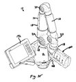
- FIG. 1 is a front perspective view of the portable CMM of the present invention including an articulated arm and attached host computer;
- FIG. 2 is a rear perspective view of the CMM of FIG. 1;
- FIG. 3 is a right side view of the CMM of FIG. 1 (with the host computer removed);
- FIG. 3A is a right side view of the CMM of FIG. 1 with slightly modified protective sleeves covering two of the long joints;
- FIG. 4 is a partially exploded, perspective view of the CMM of the present invention depicting the base and the first articulated arm section;
- FIG. 5 is a partially exploded, perspective view of the CMM of the present invention depicting the base, first arm section and partially exploded second arm section;
- FIG. 6 is a partially exploded, perspective view of the CMM of the present invention depicting the base, first arm section, second arm section and partially exploded third arm section;
- FIG. 7 is an exploded, perspective view depicting a pair of encoder/bearing cartridges being assembled between two dual socket joints in accordance with the present invention
- FIG. 8 is a front elevation view of the bearing/encoder cartridges and dual socket joints of FIG. 7;
- FIG. 9 is an exploded, perspective view of a short bearing/encoder cartridge in accordance with the present invention.
- FIG. 9A is an exploded, perspective view similar to FIG. 9, but showing a single read head
- FIG. 9B is an exploded, perspective view, similar to FIG. 9, but showing four read heads
- FIG. 9C is a perspective view of FIG. 9B after assembly
- FIG. 9D is an exploded, perspective view, similar to FIG. 9, but showing three read heads
- FIG. 9E is a perspective view of FIG. 9D after assembly
- FIG. 10 is a cross-sectional elevation view of the cartridge of FIG. 9;
- FIG. 11 is an exploded, perspective view of a long bearing/encoder cartridge in accordance with the present invention.
- FIG. 11A is an exploded, perspective view similar to FIG. 11, but showing a single read head
- FIG. 12 is a cross-sectional elevation view of the cartridge of FIG. 11;
- FIG. 12A is a cross-sectional elevation view of the cartridge of FIG. 12 depicting the dual read heads being rotatable with the shaft;
- FIG. 13 is an exploded, perspective view of still another bearing/encoder cartridge in accordance with the present invention.
- FIG. 13A is an exploded, perspective view similar to FIG. 13, but showing a single read head
- FIG. 14 is a cross-sectional elevation view of the cartridge of FIG. 13;
- FIG. 15 is an exploded, perspective view of a bearing/encoder cartridge and counter balance spring in accordance with the present invention.
- FIG. 15A is an exploded, perspective view similar to FIG. 15, but showing a single read head
- FIG. 16 is a cross-sectional elevation view of the cartridge and counter balance of FIG. 15;
- FIG. 17 is a top plan view of a dual read head assembly for a larger diameter bearing/encoder cartridge used in accordance with the present invention.
- FIG. 18 is a cross-sectional elevation view along the line 18 - 18 of FIG. 17;
- FIG. 19 is a bottom plan view of the dual read head assembly of FIG. 17;
- FIG. 20 is a top plan view of a dual read head assembly for a smaller diameter bearing/encoder cartridge in accordance with the present invention.
- FIG. 21 is a cross-sectional elevation view along the line 21 - 21 of FIG. 20;
- FIG. 22 is a bottom plan view of the dual read head assembly of FIG. 20;
- FIG. 23A is a block diagram depicting the electronics configuration for the CMM of the present invention using a single read head and FIG. 23B is a block diagram depicting the electronics configuration for the CMM of the present invention using a dual read head;
- FIG. 24 is a cross-sectional elevation view longitudinally through the CMM of the present invention (with the base removed);
- FIG. 24A is a cross-sectional elevation view of the CMM of FIG. 3A;
- FIG. 25 is an enlarged cross-sectional view of a portion of FIG. 24 depicting the base and first long joint segment of the CMM of FIG. 24;
- FIG. 25A is a perspective view of the interconnection between a long and short joint in accordance with an alternative embodiment of the present invention.
- FIG. 25B is a cross-sectional elevation view longitudinally through a portion of FIG. 25A;
- FIG. 26 is an enlarged cross-sectional view of a portion of FIG. 24 depicting the second and third long joint segments;
- FIGS. 26A and B are enlarged cross-sectional views of portions of FIG. 24A depicting the second and third long joints as well as the probe;
- FIG. 27 is a cross-sectional, side elevation view through a first embodiment of the measurement probe in accordance with the present invention.
- FIG. 27A is a side elevation view of another embodiment of a measurement probe in accordance with the present invention.
- FIG. 27B is a cross-sectional elevation view along the line 27 B- 27 B of FIG. 27A;
- FIG. 27C is a perspective view of a pair of “take” or “confirm” switches used in FIGS. 27 A-B;
- FIGS. 28 A-C are sequential elevation plan views depicting the integrated touch probe assembly and conversion to hard probe assembly in accordance with the present invention.
- FIG. 29 is a cross-sectional, side elevation view through still another embodiment of a measurement probe in accordance with the present invention.
- FIG. 30 is a side elevation view of a measurement probe with a seventh axis transducer
- FIG. 31 is a side elevation view, similar to FIG. 30, but including a removable handle
- FIG. 32 is an end view of the measurement probe of FIG. 31;
- FIG. 33 is a cross-sectional elevation view of the measurement probe of FIG. 31;
- FIG. 34A is a side-perspective view of a first embodiment of the integrated line scanner of the present invention.
- FIG. 34B is a partially cut-away, perspective view of the integrated line scanner of FIG. 34A;
- FIG. 35 is a front perspective view of the portable CMM of the present invention including an articulated arm with integrated line laser scanner and attached host computer;
- FIG. 36 is a side profile of the hand-held line laser scanner unit portion of the articulated arm of FIG. 35 schematically showing operation thereof;
- FIG. 37 is a top plan view of the hand held line laser scanner unit of FIG. 36 showing operation thereof;
- FIG. 38 is a cross-section view of the hand-held line laser scanner of FIG. 36;
- FIG. 39 is a block diagram depicting operation of the articulated arm of FIG. 35 with integrated line laser scanner
- FIG. 40 is a perspective view of yet another embodiment of a line laser scanner mounted on the measurement probe of FIG. 31;
- FIGS. 41 and 42 are respectively rear and front perspective views of the line laser scanner of FIG. 40;
- FIGS. 43, 44 and 45 are respectively side-elevation, front, and rear views of the line laser scanner of FIG. 40;
- FIG. 46 is a front elevation view, similar to FIG. 44 of the line laser scanner of FIG. 40;
- FIG. 47 is a cross-sectional elevation view along the line 47 - 47 of FIG. 46;
- FIG. 48 is a partially exploded view depicting the attachment of a line laser scanner onto the probe of FIG. 31;
- FIG. 49 is a front perspective view depicting a kinematic mount used with the line laser scanner of FIG. 40.
- FIG. 50 is a rear perspective view of the kinematic mount of FIG. 49.
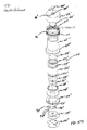
- CMM 10 comprises a multijointed, manually operated, articulated arm 14 attached at one end to a base section 12 and attached at the other end to a measurement probe 28 .
- Arm 14 is constructed of basically two types of joints, namely a long joint (for swivel motion) and a short joint (for hinge motion).
- the long joints are positioned substantially axially or longitudinally along the arm while the short joints are preferably positioned at 90° to the longitudinal axis of the arm.
- the long and short joints are paired up in what is commonly known as a 2-2-2 configuration (although other joint configurations such as 2-1-2, 2-1-3, 2-2-3, etc. may be employed) Each of these joint pairs are shown in FIGS. 4 - 6 .
- FIG. 4 depicts an exploded view of the first joint pair, namely long joint 16 and short joint 18 .
- FIG. 4 also depicts an exploded view of the base 12 including a portable power supply electronics 20 , a portable battery pack 22 , a magnetic mount 24 and a two-piece base housing 26 A and 26 B. All of these components will be discussed in more detail hereinafter.
- each of the primary components of articulated arm 14 may be threadably attached thereby eliminating a large number of fasteners associated with prior art CMMs.
- magnetic mount 24 is threadably attached to first long joint 16 .
- such threading is tapered threading which is self-locking and provides for increased axial/bending stiffness.
- the primary components of the articulated arm may have complimentary tapered male and female ends with associated flanges, such flanges being bolted together.
- the second set of a long and short joint is shown being attached to the first set.
- the second joint set includes long joint 30 and short joint 32 .
- long joint 30 is threadably attached to threading on the interior surface of long joint 16 .
- the third joint set includes a third long joint 34 and a third short joint 36 .
- Third long joint 34 threadably attaches to threading on the interior surface of second short joint 32 .
- probe 28 threadably attaches to short joint 36 .
- each short joint 18 , 32 and 36 is constructed of cast and/or machined aluminum components or alternatively, lightweight stiff alloy or composite.
- Each long joint 16 , 30 and 34 is preferably constructed of cast and/or machined aluminum, lightweight stiff alloy and/or fiber reinforced polymer.
- the mechanical axes of the three aforementioned joint pairs i.e., pair 1 comprises joint pairs 16 , 18 , pair 2 comprises joint pairs 30 , 32 and pair 3 comprises joint pairs 34 , 36 ) are aligned with respect to the base for smooth, uniform mechanical behavior.
- the aforementioned tapered construction from base 12 to probe 28 is preferred to promote increased stiffless at the base where loads are greater and smaller profile at the probe or handle where unobstructed use is important.
- each short joint is associated with a protective bumper 38 on either end thereof and each long probe is covered with a protective sleeve 40 or 41 .
- first long joint 16 is protected by the base housing 26 A, B which provides the same type of protection as sleeves 40 , 41 provide for the second and third long joints 30 , 34 .
- each of the joints of the articulated arm utilizes a modular bearing/encoder cartridge such as the short cartridge 42 and the long cartridge 44 shown in FIGS. 7 and 8.
- These cartridges 42 , 44 are mounted in the openings of dual socket joints 46 , 48 .
- Each socket joint 46 , 48 includes a first cylindrical extension 47 having a first recess or socket 120 and a second cylindrical extension 49 having a second recess or socket 51 .
- sockets 120 and 51 are positioned 90 degrees to one another although other relative, angular configurations may be employed.
- Short cartridge 42 is positioned in each socket 51 of dual socket joints 46 and 48 to define a hinge joint
- long cartridge 44 is positioned in socket 120 of joint 46 (see FIG.
- Modular bearing/encoder cartridges 42 , 44 permit the separate manufacture of a pre-stressed or preloaded dual bearing cartridge on which is mounted the modular encoder components. This bearing encoder cartridge can then be fixedly attached to the external skeletal components (i.e., the dual socket joints 46 , 48 ) of the articulated arm 14 .
- the use of such cartridges is a significant advance in the field as it permits high quality, high speed production of these sophisticated subcomponents of articulated arm 14 .
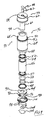
- each cartridge includes a pre-loaded bearing arrangement and a transducer which in this embodiment, comprises a digital encoder.
- Cartridge 44 includes a pair of bearings 50 , 52 separated by an inner sleeve 54 and outer sleeve 56 . It is important that bearings 50 , 52 are pre-loaded. In this embodiment, such preload is provided by sleeves 54 , 56 being of differing lengths (inner sleeve 54 is shorter than outer sleeve 56 by approximately 0.0005 inch) so that upon tightening, a preslected preload is generated on bearings 50 , 52 . Bearings 50 , 52 are sealed using seals 58 with this assembly being rotatably mounted on shaft 60 . At its upper surface, shaft 60 terminates at a shaft upper housing 62 . An annulus 63 is defined between shaft 60 and shaft upper housing 62 .
- This entire assembly is positioned within outer cartridge housing 64 with the shaft and its bearing assembly being securely attached to housing 64 using a combination of an inner nut 66 and an outer nut 68 . Note that upon assembly, the upper portion 65 of outer housing 64 will be received within annulus 63 . It will be appreciated that the aforementioned preload is provided to bearings 50 , 52 upon the tightening of the inner and outer nuts 66 , 68 which provide compression forces to the bearings and, because of the difference in length between the inner and outer spacers 54 , 56 , the desired preload will be applied.
- bearings 50 , 52 are duplex ball bearings.
- the bearing faces be as parallel as possible.
- the parallelism affects the evenness of the pre-loading about the circumference of the bearing. Uneven loading will give the bearing a rough uneven running torque feel and will result in unpredictable radial run out and reduced encoder performance. Radial run out of the modularly mounted encoder disk (to be discussed below) will result in an undesirable fringe pattern shift beneath the reader head. This results in significant encoder angular measurement errors.
- the stiffness of the preferably duplex bearing structure is directly related to the separation of the bearings. The farther apart the bearings, the stiffer will be the assembly.
- the spacers 54 , 56 are used to enhance the separation of the bearings. Since the cartridge housing 64 is preferably aluminum, then the spacers 54 , 56 will also preferably be made from aluminum and precision machined in length and parallelism. As a result, changes in temperature will not result in differential expansion which would compromise the preload. As mentioned, the preload is established by designing in a known difference in the length of spacers 54 , 56 . Once the nuts 66 , 68 are fully tightened, this differential in length will result in a bearing preload. The use of seals 58 provide sealed bearings since any contamination thereof would effect all rotational movement and encoder accuracy, as well as joint feel.
- cartridge 44 preferably includes a pair of spaced bearings
- cartridge 44 could alternatively include a single bearing or three or more bearings.
- each cartridge needs at least one bearing as a minimum.
- the joint cartridges of the present invention may either have unlimited rotation or as an alternative, may have a limited rotation.
- a groove 70 on a flange 72 on the outer surface of housing 64 provides a cylindrical track which receives a shuttle 74 .
- Shuttle 74 will ride within track 70 until it abuts a removable shuttle stop such as the rotation stop set screws 76 whereupon rotation will be precluded.
- the amount of rotation can vary depending on what is desired. In a preferred embodiment, shuttle rotation would be limited to less than 720°. Rotational shuttle stops of the type herein are described in more detail in commonly owned U.S. Pat. No. 5,611,147, all of the contents of which have been incorporated herein by reference.
- the joint used in the present invention may have unlimited rotation.
- a known slip ring assembly is used.
- shaft 60 has a hollow or axial opening 78 therethrough which has a larger diameter section 80 at one end thereof. Abutting the shoulder defined at the intersection between axial openings 78 and 80 is a cylindrical slip ring assembly 82 .
- Slip ring assembly 82 is non-structural (that is, provides no mechanical function but only provides an electrical and/or signal transfer function) with respect to the preloaded bearing assembly set forth in the modular joint cartridge. While slip ring assembly 82 may consist of any commercially available slip ring, in a preferred embodiment, slip ring assembly 82 comprises a H series slip ring available from IDM Electronics Ltd.
- slip rings are compact in size and with their cylindrical design, are ideally suited for use in the opening 80 within shaft 60 .
- Axial opening 80 through shaft 60 terminates at an aperture 84 which communicates with a channel 86 sized and configured to receive wiring from the slip ring assembly 82 .
- Such wiring is secured in place and protected by a wire cover 88 which snaps onto and is received into channel 86 and aperture 84 .
- Such wiring is shown diagrammatically at 90 in FIG. 10.
- modular cartridge 44 include both a preloaded bearing structure which has been described above as well as a modular encoder structure which will now be described.
- the preferred transducer used in the present invention comprises a modular optical encoder having two primary components, a read head 92 and a grating disk 94 .
- a pair of read heads 92 are positioned on a read head connector board 96 .
- Connector board 96 is attached (via fasteners 98 ) to a mounting plate 100 .
- Disk 94 is preferably attached to the lower bearing surface 102 of shaft 60 (preferably using a suitable adhesive) and will be spaced from and in alignment with read heads 92 (which is supported and held by plate 100 ).
- FIGS. 9 and 10 depict a double read head 92 ; however, it will be appreciated that more than two read heads may be used or, in the alternative, a single read head as shown in FIG. 9A may be used.
- FIGS. 9 B-C show four read heads 92 received in a plate 100 and spaced at 90 degree intervals (although different relative spacings may be appropriate).
- FIGS. 9 D-E show three read heads 92 received in a plate 100 and spaced at 120 degree intervals (although different relative spacing may be appropriate).
- a hole (not shown) is provided through housing 64 at a location adjacent disk 94 .
- a tool (not shown) is then used to push disk 94 into proper alignment whereupon adhesive between disk 94 and shaft 66 is cured to lock disk 94 in place.
- a hole plug 73 is then provided through the hole in housing 64 .
- disk 94 and read head 92 may be reversed whereby disk 94 is attached to housing 56 and read head 92 rotates with shaft 60 .
- FIG. 12A Such an embodiment is shown in FIG. 12A where board 96 ′ is attached (via adhesive) to shaft 60 ′ for rotation therewith.
- a pair of read heads 92 ′ are attached to board 96 ′ and thus will rotate with shaft 60 ′.
- the disk 94 ′ is positioned on a support 100 ′ which is attached to housing 64 ′.
- the disk 94 or read head 92 may be mounted for rotation with the shaft. All that is important is that disk 94 and read head 92 be positioned in a cartridge (or joint) so as to be rotatable with respect to each other while maintaining optical communication.
- the rotational encoder employed in the present invention is similar to that disclosed in U.S. Pat. Nos. 5,486,923 and 5,559,600, all of the contents of which are incorporated herein by reference.
- Such modular encoders are commercially available from MicroE Systems under the trade name Pure Precision Optics. These encoders are based on physical optics that detect the interference between diffraction orders to produce nearly perfect sinusoidal signals from a photo detector array (e.g., read head(s)) inserted in the fringe pattern. The sinusoidal signals are electronically interpolated to allow detection of displacement that is only a fraction of the optical fringe.
- the laser beam is first collimated by a lens and then sized by an aperture.
- the collimated size beam passes through a grating that diffracts the light into discrete orders with the 0 th and all even orders suppressed by the grating construction. With the 0 order suppressed, a region exists beyond the diverging 3 rd order where only the ⁇ 1 st orders overlap to create a nearly pure sinusoidal interference.
- One or more photodetector arrays read neads
- Electronics amplify, normalize and interpolate the output to the desired level of resolution.
- a significant advantage of the aforementioned optical encoder is that the precision of the standoff orientation and distance or the distance and orientation of the read head with respect to the encoder disk is far less stringent. This permits a high accuracy rotational measurement and an easy-to-assemble package. The result of using this “geometry tolerant” encoder technology results in a CMM 10 having significant cost reductions and ease of manufacturing.
- the preferred embodiment of the present invention also encompasses any optical fringe pattern which allow the read head to measure relative motion.
- fringe pattern means any periodic array of optical elements which provide for the measurement of motion.
- Such optical elements or fringe pattern could be mounted on a rotating or stationary disk as described above, or alternatively, could be deposited, secured or otherwise positioned or reside upon any of the relatively moving components (such as the shaft, bearings or housing) of the cartridge.
- the read head and associated periodic array or pattern does not necessarily need to be based on optics (as described above) at all. Rather, in a broader sense, the read head could read (or sense) some other periodic pattern of some other measurable quantity or characteristic which can be used to measure motion, generally rotary motion. Such other measurable characteristics may include, for example, reflectivity, opacity, magnetic field, capacitance, inductance or surface roughness. (Note that a surface roughness pattern could be read using a read head or sensor in the form of a camera such as a CCD camera). In such cases, the read head would measure, for example, periodic changes in magnetic field, reflectivity, capacitance, inductance, surface roughness or the like.
- the term “read head” means any sensor or transducer and associated electronics for analysis of these measurable quantities or characteristics with an optical read head being just one preferred example.
- the periodic pattern being read by the read head can reside on any surface so long as there is relative (generally rotary) motion between the read head and periodic pattern.
- Examples of the periodic pattern include a magnetic, inductive or capacitive media deposited on a rotary or stationary component in a pattern.
- surface roughness is the periodic pattern to be read, there is no need to deposit or otherwise provide a separate periodic media since the surface roughness of any component in communication with the associated read head (probably a camera such as a CCD camera) may be used.
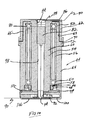
- FIGS. 9 and 10 depict the elements of the modular bearing and encoder cartridge for axially long joint 16 .
- These cartridge assemblies are substantially similar to that shown FIGS. 9 and 10 and so are designated by 44 ′. Minor differences are evident from the FIGURES relative to cartridge 44 with respect to, for example, a differently configured wire cap/cover 88 ′, slightly differing wire funnels/covers 104 ′, 106 ′ and the positioning of flange 72 ′ at the upper end of housing 64 ′. Also, the flanges between housing 64 ′ and shaft upper housing 62 are flared outwardly.
- the relative lengths of the various components shown in FIGS. 11 and 12 may differ slightly from that shown in FIGS. 9 and 10. Since all of these components are substantially similar, the components have been given the same identification numeral with the addition of a prime.
- FIG. 11A is similar to FIG. 11, but depicts a single read head embodiment.
- FIGS. 13 and 14 similar exploded and cross-sectional views are shown for the bearing and encoder cartridges in short hinge joints 32 and 36 .
- the cartridges for the short hinge joints 32 and 36 are substantially similar to the cartridge 44 discussed in detail above and therefore the components of these cartridges are identified at 44 ′′ with similar components being identified using a double prime. It will be appreciated that because cartridges 44 ′′ are intended for use in short joints 32 , 36 , no slip ring assembly is required as the wiring will simply pass through the axial openings 78 ′′, 80 ′′ due to the hinged motion of these joints.
- FIG. 13A is similar to FIG. 13, but depicts a single read head embodiment.
- FIGS. 15 and 16 the modular bearing/encoder cartridge for short hinge joint 18 is shown at 108 .
- This counter balance assembly includes a counter balance spring 110 which is received over housing 64 ′′ and provides an important counter balance function to CMM 10 .
- FIG. 15A is similar to FIG. 15, but depicts a single read head embodiment.
- more than one read head may be used in the encoder.
- angle measurement of an encoder is effected by disk run out or radial motion due to applied loads. It has been determined that two read heads positioned at 180° from each other will result in run out causing cancellation effects in each read head. These cancellation effects are averaged for a final “immune” angle measurement. Thus, the use of two read heads and the resultant error cancellation will result in a less error prone and more accurate encoder measurement.
- FIGS. 17 - 19 depict the bottom, cross-sectional and top views respectively for a dual read head embodiment useful in, for example, a larger diameter cartridge such as found in joints 16 and 18 (that is, those joints nearest the base).
- a cartridge end cap 100 has mounted thereto a pair of circuit boards 96 with each circuit board 96 having a read head 92 mechanically attached thereto.
- the read heads 92 are preferably positioned 180° apart from each other to provide for the error cancellation resulting from the run out or radial motion of the disk.
- Each board 96 additionally includes a connector 93 for attachment of the circuit board 96 to the internal bus and/or other wiring as will be discussed hereinafter.
- FIGS. 20 - 22 depict substantially the same components as in FIGS. 17 - 19 with the primary difference being a smaller diameter cartridge end cap 100 .
- This smaller diameter dual read head embodiment would be associated with the smaller diameter cartridges of, for example, joints 30 , 32 , 34 and 36 .
- CMM 10 preferably includes an external bus (preferably a USB bus) 260 and an internal bus (preferably RS-485) 261 which is designed to be expandable for more encoders as well as either an externally mounted rail or additional rotational axes such as a seventh axis.
- the internal bus is preferably consistent with RS485 and this bus is preferably configured to be used as a serial network in a manner consistent with the serial network for communicating data from transducers in a portable CMM arm as disclosed in commonly assigned U.S. Pat. No. 6,219,928, all of the contents of which have been incorporated herein by reference.
- each encoder in each cartridge is associated with an encoder board.
- the encoder board for the cartridge in joint 16 is positioned within base 12 and is identified at 112 in FIG. 25.
- the encoders for joints 18 and 30 are processed on a dual encoder board which is located in the second long joint 30 and is identified at 114 in FIG. 26.
- FIG. 26 also depicts a similar dual encoder board 116 for the encoders used in joints 32 and 34 , board 116 being positioned in third long joint 34 as shown in FIG. 26.
- the end encoder board 118 is positioned within measurement probe handle 28 as shown in FIG. 24 and is used to process the encoders in short joint 36 .
- Each of the boards 114 , 116 and 118 are associated with a thermocouple to provide for thermal compensation due to temperature transients.
- Each board 112 , 114 , 116 and 118 incorporates embedded analog-to-digital conversion, encoder counting and serial port communications.
- Each board also has read programmable flash memory to allow local storage of operating data.
- the main processor board 112 is also field programmable through the external USB bus 260 .
- the internal bus (RS-485) 261 is designed to be expandable for more encoders which also includes either an externally mounted rail and/or seventh rotation axis. An axis port has been provided to provide internal bus diagnosis.
- Multiple CMMs of the type depicted at 10 in these FIGURES may be attached to a single application due to the capabilities of the external USB communications protocol. Moreover, multiple applications may be attached to a single CMM 10 for the very same reasons.
- each board 112 , 114 , 116 and 118 includes a 16-bit digital signal processor such as the processor available from Motorola under the designation DSP56F807.
- This single processing component combines many processing features including serial communication, quadrature decoding, A/D converters and on-board memory thus allowing a reduction of the total number of chips needed for each board.
- each of the encoders is associated with an individualized identification chip 120 .
- This chip will identify each individual encoder and therefore will identify each individual bearing/encoder modular cartridge so as to ease and expedite quality control, testing, and repair.
- FIG. 23B is an electronics block diagram which is similar to FIG. 23A, but depicts the dual read head embodiment of FIGS. 10, 12, 14 and 16 - 22 .
- the first long joint 16 includes a relatively long cartridge 44 , the upper end of which has been inserted into a cylindrical socket 120 of dual socket joint 46 .
- Cartridge 44 is securely retained within socket 120 using a suitable adhesive.
- the opposite, lower end of cartridge 44 is inserted into an extension tube, which in this embodiment may be an aluminum sleeve 122 (but sleeve 122 may also be comprised of a stiff alloy or composite material).
- Cartridge 44 is secured in sleeve 122 again using a suitable adhesive.
- the lower end of sleeve 122 includes a larger outer diameter section 124 having internal threading 126 thereon.
- Such threading is outwardly tapered and is configured to threadably mate with inwardly tapered threading 128 on magnetic mount housing 130 as is clearly shown in FIG. 4.
- the tapered thread is of the NPT type which is self-tightening and therefore no lock nuts or other fastening devices are needed. This threading also allows for and should include a thread locking agent.
- long cartridge 44 ′ is adhesively secured in the cylindrical opening 120 ′ of dual socket joint 46 ′.
- the outer housing 64 ′ of cartridge 44 ′ includes a shoulder 132 defined by the lower surface of flange 72 ′. This shoulder 132 supports cylindrical extension tube 134 which is provided over and surrounds the outer surface of housing 64 ′. Extension tubes are used in the joints to create a variable length tube for attachment to a threaded component. Extension tube 134 thus extends outwardly from the bottom of cartridge 64 ′ and has inserted therein a threaded sleeve 136 .
- Extension tube 134 is composed of a composite material such as an appropriate carbon fiber composite while threadable sleeve 136 is composed of aluminum so as to match the thermal properties of the dual socket joint 48 .
- PC board 114 is fastened to a support 146 which in turn is secured to dual socket joint support 142 .
- sleeve 136 ′ of FIG. 25B has a smooth tapered end 137 which is received in a complimentary tapered socket support 142 ′.
- a flange 139 extends circumferentially outwardly from sleeve 136 ′ with an array of bolt holes (in this case 6 ) therethrough for receiving threaded bolts 141 .
- Bolts 141 are threadably received in corresponding holes along the upper surface of socket support 142 ′.
- An extension tube 134 ′ is received over sleeve 136 ′ as in the FIG. 26 embodiment.
- the complimentary tapered male and female interconnections for the joints provide improved connection interfaces relative to the prior art.
- long cartridge 44 ′′ of third long joint 34 is secured to arm 14 in a manner similar to cartridge 44 ′ of long joint 30 . That is, the upper portion of cartridge 44 ′′ is adhesively secured into an opening 120 ′′ of dual socket joint 46 ′′.
- An extension tube 148 (preferably composed of a composite material as described with respect to tube 134 ) is positioned over outer housing 64 ′′ and extends outwardly thereof so as to receive a mating sleeve 150 which is adhesively secured to the interior diameter of extension tube 148 .
- Mating sleeve 150 terminates at a tapered section having outer threading 152 and mates with complimentary interior threading 153 on dual socket joint support 154 which has been adhesively attached to a cylindrical socket 156 within dual socket joint 148 ′.
- Printed circuit board 116 is similarly connected to the dual socket joint using the PCB support 146 ′ which is secured to dual socket joint support 154 .
- the short cartridges 44 ′ in FIGS. 13 and 14 and 108 of FIG. 15 are simply positioned between two dual socket joints 46 , 48 and are secured within the dual socket joints using an appropriate adhesive. As a result, the long and short cartridges are easily attached to each other at right angles (or, if desired, at angles other than right angles).
- the modular bearing/transducer cartridges as described above constitute an important technological advance in portable CMM's such as shown, for example, in U.S. Pat. No. 5,794,356 to Raab and U.S. Pat. No. 5,829,148 to Eaton. This is because the cartridge (or housing of the cartridge) actually defines a structural element of each joint which makes up the articulated arm.
- structural element means that the surface of the cartridge (e.g., the cartridge housing) is rigidly attached to the other structural components of the articulated arm in order to transfer rotation without deformation of the arm (or at most, with only de minimis deformation).
- the present invention has eliminated the need for separate transfer elements (e.g., transfer members) by combining the functionality of the joint and transfer elements into a singular modular component (i.e., cartridge).
- the present invention utilizes an articulated arm made up of a combination of longer and shorter joint elements (i.e., cartridges), all of which are structural elements of the arm. This leads to better efficiencies relative to the prior art.
- the number of bearings used in a joint/transfer member combination in the '148 and '582 patent was four (two bearings in the joint and two bearings in the transfer member) whereas the modular bearing/transducer cartridge of the present invention may utilize a minimum of one bearing (although two bearings are preferred) and still accomplish the same functionality (although in a different and improved way).
- FIGS. 24 A and 26 A-B are cross-sectional views, similar to FIGS. 24 - 26 , but showing the dual read head embodiments of FIGS. 10, 12, 14 and 16 - 22 and are further cross-sections of the CMM 10 ′ shown in FIG. 3A.
- the overall length of articulated arm 14 and/or the various arm segments may vary depending on its intended application.
- the articulated arm may have an overall length of about 24 inches and provide measurements on the order of about 0.0002 inch to 0.0005 inch.
- This arm dimension and measurement accuracy provides a portable CMM which is well suited for measurements now accomplished using typical hand tools such as micrometers, height gages, calipers and the like.
- articulated arm 14 could have smaller or larger dimensions and accuracy levels.
- larger arms may have an overall length of 8 or 12 feet and associated measurement accuracies of 0.001 inch thus allowing for use in most real time inspection applications or for use in reverse engineering.
- CMM 10 may also be used with a controller mounted thereto and used to run a relatively simplified executable program as disclosed in aforementioned U.S. Pat. No. 5,978,748 and application Ser. No. 09/775,226; or may be used with more complex programs on host computer 172 .
- each of the long and short joints are protected by an elastomeric bumper or cover which acts to limit high impact shock and provide ergonomically pleasant gripping locations (as well as an aesthetically pleasing appearance).
- the long joints 16 , 30 and 34 are all protected by a rigid plastic (e.g., ABS) replaceable cover which serves as an impact and abrasion protector.
- this rigid plastic replaceable cover comes in the form of the two-piece base housing 26 A and 26 B as is also shown in FIG. 4.
- Long joints 30 and 34 are each protected by a pair of cover pieces 40 and 41 which, as shown in FIGS.
- this rigid plastic replaceable cover for each long joint 30 and 34 will surround the preferably composite (carbon fiber) extension tube 134 and 148 , respectively.
- one of the covers in this case cover section 41 , includes a slanted support post 166 integrally molded therein which limits the rotation at the elbow of the arm so as to restrict probe 28 from colliding with base 12 in the rest position. This is best shown in FIGS. 3, 24 and 26 . It will be appreciated that post 166 will thus limit unnecessary impact and abrasion.
- probe 28 may also include a replaceable plastic protective cover made from a rigid plastic material.
- FIGS. 3A, 24A and 26 A-B depict alternative protective sleeves 40 ′, 41 ′ which also have a clam shell construction, but are held in place using straps or spring clips 167 rather than threaded fasteners.
- Each of the short joints 18 , 32 and 36 include a pair of elastomeric (e.g., thermoplastic rubber such as Santoprene®) bumpers 38 as previously mentioned and as shown clearly in FIGS. 1 - 3 and 5 - 6 .
- Bumpers 38 may either be attached using a threaded fastener, a suitable adhesive or in any other suitable manner. Elastomeric or rubber bumper 38 will limit the high impact shock as well as provide an aesthetically pleasing and ergonomically pleasant gripping location.
- base-housing 26 A, B includes at least two cylindrical bosses for the mounting of a sphere as shown at 168 in FIG. 3.
- the sphere may be used for the mounting of a clamp type computer holder 170 which in turn supports a portable or other computer device 172 (e.g., the “host computer”).
- a cylindrical boss is provided on either side of base housing 26 A, B so that the ball and clamp computer mount may be mounted on either side of CMM 10 .
- Probe 28 includes a housing 196 having an interior space 198 therein for housing printed circuit board 118 .
- housing 196 constitutes a dual socket joint of the type described above and includes a socket 197 in which is bonded a support member 199 for supporting circuit board 118 .
- handle 28 includes two switches, namely a take switch 200 and a confirm switch 202 . These switches are used by the operator to both take a measurement (take switch 200 ) and to confirm the measurement (confirm switch 202 ) during operation. In accordance with an important feature of this invention, the switches are differentiated from each other so as to minimize confusion during use.
- This differentiation may come in one or more forms including, for example, the switches 200 , 202 being of differing height and/or differing textures (note that switch 202 has an indentation as opposed to the smooth upper surface of switch 200 ) and/or different colors (for example, switch 200 may be green and switch 202 may be red).
- an indicator light 204 is associated with switches 200 , 202 for indicating proper probing.
- the indicator light 204 is a two-color light so that, for example, light 204 is green upon taking of a measurement (and pressing the green take button 200 ) and is red for confirming a measurement (and pressing the red button 202 ).
- a switch circuit board 208 is provided for the mounting of buttons 200 , 202 and lamp 204 and is supported by support member 199 .
- Switch board 208 is electrically interconnected with board 118 which houses components for processing the switches and light indicator as well as for the processing of short hinge joint 36 .
- probe 28 includes a permanently installed touch trigger probe as well as a removable cap for adapting a fixed probe while protecting the touch trigger probe.
- the touch probe mechanism is shown at 210 in FIG. 27 and is based on a simplified three point kinematics seat.
- This conventional construction comprises a nose 212 which contacts a ball 214 biased by a contact spring 216 .
- Three contact pins (one pin being shown at 218 ) are in contact with an underlying electric circuit.
- Application of any forces against the probe nose 212 results in lifting of any one of the three contact pins 218 resulting in an opening of the underlying electric circuit and hence activation of a switch.
- touch trigger probe 210 will operate in conjunction with the front “take” switch 200 .
- a protective threaded cover 220 is threadably attached to threading 222 surrounding trigger probe 210 .
- the removable cap 220 is removed and a desired fixed probe such as that shown at 224 in FIGS. 27 and 28A-C is threadably attached to threading 222 .
- a desired fixed probe such as that shown at 224 in FIGS. 27 and 28A-C
- Touch trigger probe assembly 210 is mounted in a housing 228 which is threadably received into threaded connector 230 which forms a part of probe housing 196 .
- This threadable interconnection provides for the full integration of touch trigger probe 210 into probe 28 .
- the provision of a fully integrated touch probe represents an important feature of the present invention and is distinguishable from prior art detachable touch probes associated with prior art CMMs.
- the permanently installed touch trigger probe is also easily convertible to a hard probe as described above.
- FIGS. 27 A-C disclose yet another preferred embodiment for a measurement probe in accordance with the present invention.
- a measurement probe is shown at 28 ′ and is substantially similar to measurement probe 28 in FIG. 27 with the primary difference residing in the configuration of the “take” and “confirm” switches.
- measurement probe 28 ′ utilizes two pairs of arcuate oblong switches 200 a - b and 202 a - b .
- Each respective pair of oblong switches 202 a - b and 200 a - b correspond respectively to the take switch and the confirm switch as described above with respect to FIG. 27.
- each pair of oblong switches 202 and 200 surround virtually the entire circumference (or at least the majority of the circumference) of the measurement probe and therefore are more easily actuatable by the operator of the portable CMM.
- an indicator light 204 is associated with each switch with the light 204 and switches 200 , 202 being mounted on respective circuit boards 208 .
- switches 200 , 202 may be differentiated using for example, different heights, different textures and/or different colors.
- switches 200 , 202 have a slight float such that the button may be actuated when pressed down in any location therealong.
- an outer protective covering of the type described above is used at 206 and provided over a portion of probe 28 ′.
- Measurement probe 232 is similar to measurement probe 28 of FIG. 27 with the primary difference being that probe 232 includes a rotating handle cover 234 .
- Rotating cover 234 is mounted on a pair of spaced bearings 236 , 238 which in turn are mounted on an inner core or support 240 such that cover 234 is freely rotatable (via bearings 236 , 238 ) about inner core 240 .
- Bearings 236 , 238 are preferably radial bearings and minimize the parasitic torques on the arm due to probe handling.
- the switch plate 208 ′ and corresponding switches 200 ′, 202 ′ and LED 204 ′ are all mounted to rotating handle cover 234 for rotation therewith.
- electrical connectivity to processing circuit board 118 ′ is provided using a conventional slip ring mechanism 242 which comprises a known plurality of spaced spring fingers 242 which contact stationary circular channels 244 .
- these contact channels 244 are electrically connected to circuit board 118 ′.
- the rotating handle cover 234 and switch assembly is thus electrically coupled to the inner core or probe shaft 240 and electronics board 118 ′ using the slip ring conductor 242 .
- the rotation of the probe handle 234 permits switches 200 ′, 202 ′ to be oriented conveniently for the user.
- the cover 234 is preferably comprised of a rigid polymer and is provided with appropriate indentations 246 and 248 to allow easy and convenient gripping and manipulation by the probe operator.
- probe 232 is quite similar to probe 28 including the provision of a permanently and integrally installed touch probe 210 in cover 220 .
- switches 200 ′, 202 ′ are of differing heights and surface textures so as to provide ease of identification.
- the rotating cover 234 is a significant advance in the CMM field in that it can alleviate the need for an additional (i.e., seventh) axis of rotation at the probe such as disclosed in aforementioned U.S. Pat. No. 5,611,147. It will be appreciated that the addition of a seventh axis leads to a more complex and expensive CMM as well as the addition of possible error into the system.
- the use of the rotatable probe 232 alleviates the need for a “true” seventh axis as it permits the probe to provide the rotation needed for handle position at the probe end without the complexity of a seventh transducer and associated bearings, encoder and electronics.
- FIGS. 30 - 33 In the event that it is desired to utilize a measurement probe having a “true” seventh axis, that is, having a measurement probe with a seventh rotary encoder for measuring rotary rotation, such a measurement probe is shown in FIGS. 30 - 33 .
- a measurement probe 500 is shown with such measurement probe being substantially similar to the measurement probe in FIG. 27 with the primary difference being the insertion of a modular bearing/transducer cartridge 502 of the type described above, the presence of the take and confirm switches 504 , 506 on the sides of the measurement probe and the inclusion of a removable handle 508 .
- the modular bearing/transducer cartridge 502 is substantially similar to the cartridges described in detail above and include a rotatable shaft, a pair of bearings on the shaft, an optical encoder disk, at least one and preferably two optical read heads spaced from and in optical communication with the encoder disk and a housing surrounding the bearings, optical encoder disk, read head(s) and at least a portion of the shaft so as to define the discrete modular bearing/transducer cartridge.
- a circuit board 503 for the encoder electronics resides in an opening 504 with probe 500 .
- buttons 504 , 506 are positioned on either side of a downwardly projected housing portion 510 of probe 500 with the buttons being connected to an appropriate PC board 512 as in the measurement probe of the FIG. 27 embodiment.
- an indicator light 513 is positioned between buttons 504 , 506 as in the previously discussed embodiments.
- a pair of threaded openings 514 in housing 510 receive fasteners for removable attachment of handle 508 which provides for ease of rotary manipulation during use of measurement probe 500 .
- measurement probe 500 is similar to measurement probe 28 of FIG. 27 including the preferred use of permanently installed touch trigger probe at 516 as well as a removable cap for adapting a fixed probe 518 while protecting the touch trigger probe. It will be appreciated that the seventh rotary encoder 502 included in measurement probe 500 facilitates the use of CMM 10 in connection with known line laser scanners and other peripheral devices.
- a portable power supply is provided to power CMM 10 thus providing a fully portable CMM.
- CMM 10 may also be powered directly by an AC cord through an AC/DC adapter via a conventional plug-in socket.
- a conventional rechargeable battery e.g., Li-ion battery
- Battery 22 is mechanically and electrically connected into a conventional battery support 252 which in turn is electrically connected to a conventional power supply and battery recharger circuit component 254 located on circuit board 20 .
- an on/off switch 258 (see FIG. 3) and a high-speed communication port 260 (preferably a USB port).
- the joint electronics of arm 14 is connected to board 20 using an RS-485 bus.
- Battery 22 can be charged on a separate charger, or charged in place in cradle 252 as is commonly found in conventional video cameras. It will be appreciated that portable computer 172 (see FIG. 2) can operate for several hours on its built-in batteries and/or in the alternative, may be electrically connected to the power supply unit 254 of CMM 10 .
- the on-board power supply/recharger unit in accordance with the present invention is preferably positioned as an integral part of CMM 10 by locating this component as an integral part of base 12 and more specifically as a part of the plastic base housing 26 A, B.
- base housing 26 A, B includes a small storage area 259 having a pivotable lid 262 for storing spare batteries, probes, or the like.
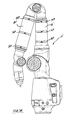
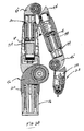
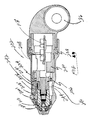
- Line laser scanner 312 includes a housing 314 for housing a digital camera 316 , a line laser 318 and the appropriate electronic circuitry 320 .
- Housing 314 surrounds the probe 28 and includes a handle 322 extending downwardly therefrom. Handle 322 is easily accessible by the operator during use of the laser scanner. It is important that the laser scanner be rotatable so as to ensure correct, on-line measurements. To that end, housing 312 is mounted on an additional (i.e., seventh) axis of rotation using an appropriate bearing structure 324 .
- this additional axis of rotation includes a transducer and thus constitute a totally separate joint in addition to the typically five or six joints in the articulated arm 14 . More preferably, the additional axis is part of a three-axis wrist for the arm (leading to the typical 2-1-3 or 2-2-3 arm configuration).
- the integrated touch probe and hard probe cover attachment as described in FIGS. 27 and 28A-C are also employed in the embodiment of FIGS. 34 A-B.
- the integrated line laser scanner 312 will operate in a known and conventional fashion but unlike prior art devices which must be retrofitted onto the end of a portable CMM, the present invention is fully integrated onto the CMM.
- electronic circuitry 320 will be fully integrated to the power and signal bus in articulated arm 14 .
- the laser scanner and CMM probe will be located in the same housing, utilize the same internal wiring and constitute a unified mechanical structure. This structure will also permit the simultaneous use or access of the laser scanner and the touch probe or hard probe.
- circuitry 320 in cooperation with host computer 172 will provide onboard image analysis and processing in real time and in an easy to operate environment with signals from the laser scanner being transmitted via the RS-485 (or similar) serial communications bus.
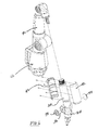
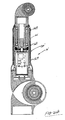
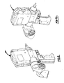
- FIGS. 35 - 39 Another embodiment of an integrated line laser scanner is shown in FIGS. 35 - 39 where CMM 10 is shown with integrated line laser scanner/probe 600 attached to probe 28 .
- a laser emitter window spaced back from probe 28 is a laser emitter window through which a scanning laser beam 604 is emitted from scanning laser 601 .
- Scanning laser 604 scans across a plane that lies perpendicular to the page as show in FIG. 36 and parallel to the page as shown in FIG. 37, which shows a plan view of scanner/probe 600 .
- Below laser emitter window 602 is CCD window 606 .
- CCD window 606 may be in fact a focusing lens of a CCD 605 located within housing 610 as will be described in further detail below.
- CCD 605 has a field of view (FOV) as shown by dashed lines 608 .
- the FOV of the CCD 605 intersects the plane defined by scanning laser beam 604 within the area 612 shown by dashed lines in FIG. 37.
- the locus of points intersecting area 612 on the object that face towards scanner/probe 600 will be illuminated by scanning laser beam 604 and imaged by CCD 605 .
- the locus of points of an object illuminated by scanning laser beam 604 will appear as a contour image on CCD 605 . Since the location and orientation of line laser scanner/probe 600 is known by CMM 10 , the precise position of area 612 on the plane defined by scanning laser beam 604 is known. As a point on an object that is illuminated by the beam is moved closer or farther away from line laser scanner/probe 600 , an image of light reflected by the laser is moved up or down on the CCD imaging plane (not shown), while points to the left and right on the imaging plane of CCD 605 correspond to locations to the left and right of an object intersecting area 612 and illuminated by scanning laser beam 604 . Thus, each pixel of CCD 605 is associated with a corresponding location in area 612 that is potentially illuminated by scanning laser beam 604 and within the FOV of CCD 605 .
- image data from CCD 605 is processed on image processing board 620 , which is a circuit board within handle 611 of housing 610 .
- CCD 605 includes a sensor board for capturing images detected by CCD 605 and converting them into a digital format, such as the FIREWIRE data format established by Apple Computers, Inc. (or any suitable high speed data communications protocol).
- the complete image is relayed in real time to novel image processing board 620 .
- Image processing board 620 includes FIREWIRE interface 622 , digital signal processor (DSP) 624 , and memory 626 . As the DSP receives image data, it processes it in real time. Software algorithms process each frame to determine the precise location of the measured object with sub-pixel accuracy.
- DSP digital signal processor
- the software algorithm analyzes the line profile along a pixel column and calculates the “center of gravity” (COV), which can be a fractional pixel location and is the point that best represents the exact location of the line.
- COV center of gravity
- the algorithm proceeds to calculate the COV for each column in the frame. Once the frame is processed, the original image is discarded and only the processed data is kept. The retained information is sent via communication chip 627 to the board at the base of the CMM in a manner similar to other data generated by the various digital encoders found at each joint.
- the data packet generated by image processing board 620 is a fraction of the size of the original image size and does not require a significant amount of communication bandwidth. From the main CMM processor, the data is sent to the host CPU along with the coincident arm position.
- the novel image processing board thus allows for on-board image processing within the arm 10 as opposed to the prior art where such image processing is accomplished in a separate unit or computer hardwired to the laser scanner via an external retrofit.
- handle 611 includes two switches, namely a take switch 200 and a confirm switch 202 . These switches are used by the operator in a probing mode to both take a measurement (take switch 200 ) and to confirm the measurement (confirm switch 202 ) during operation. Also, an indicator light 204 is associated with switches 200 , 202 for indicating proper probing. Preferably, the indicator light 204 is a two-color light so that, for example, light 204 is green upon taking of a measurement (and pressing the green take button 200 ) and is red for confirming a measurement (and pressing the red button 202 ). The use of a muticolored light is easily accomplished using a known LED as the light source for light 204 .
- take switch 200 activates the scanning process described above while the confirm switch 202 may be used for some other purpose, e.g., to cancel the previous scan.
- the function of the switches may be assigned by the software program.
- Probe 28 in FIG. 38 includes touch probe mechanism 210 and hard probe cover 220 as previously described in FIGS. 27 and 30.
- Touch probe mechanism 210 comprises a nose 212 which contacts a spring biased element. Three contact pins are in contact with an underlying electric circuit. Application of force against the probe nose 212 results in lifting of one of the three contact pins resulting in an opening of the underlying electric circuit and hence activation of a switch.
- touch trigger probe 210 will operate in conjunction with the front “take” switch 200 in a probe mode.
- a probe cover 220 is threadably removed. However, when it is desired to use a fixed probe rather than the touch trigger probe, probe cover 220 is attached as shown. It will be appreciated that while probe cover 220 has a round ball 226 attached thereto, any different and desired fixed probe configuration may be easily threadably attached to probe 28 .
- Touch probe mechanism 210 is mounted in a housing 228 which is threadably received into a threaded connector which forms a part of probe housing 110 .
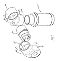
- laser scanner 700 is shown attached to a CMM 702 having the probe 500 of the type described in FIGS. 30 - 32 .
- laser scanner 700 includes a housing 704 for housing the CCD window 606 , focusing lens 605 , image processing board 620 , high speed data communications protocol interface board 622 , digital signal processor 624 and memory 626 , all of which have been described above in connection with the FIG. 38 embodiment.
- a kinematic ring which is best shown in FIGS. 49 and 50, and which includes three spaced (preferably, equidistantly or at 180 degrees apart) cut-outs or openings 707 .
- Each opening 707 receives a small clyindrical rod 708 therein.
- Cylindrical rods 708 are received in correspondingly spaced and complimentary shaped openings 710 on an inner face 712 of downwardly projected housing portion 510 of probe 500 .
- a retaining ring 714 has internal threading 716 which is threadably received by threading 222 of probe 500 which then connects housing 504 tightly to probe 500 in a precise alignment (resulting from the kinematic seat 706 ).
- laser scanner 700 operates in a similar manner to laser scanner 600 of FIG. 38, scanner 700 has the advantage of being easily removably attachable to the additional axis probe 500 (as opposed to the more permanently attached laser scanners of FIGS. 24A and 38).
- the line laser scanner of FIGS. 40 - 48 provides a fully integrated scanning device comprised of the line laser, optical filters and digital camera, all of which are connected to a high-speed data communications protocol (i.e., FIREWIRE) to a digital image processor, a DSP processor and memory for image analysis and three dimensional analysis and finally to a communications processor for communication of the resulting data packet to the bus of the articulated arm of CMM 10 and ultimately to the host computer 172 .
- a high-speed data communications protocol i.e., FIREWIRE
- the laser scanner 700 will utilize the power supply which is already integrated into the arm of CMM 10 .
- the only external cable necessary in this embodiment is a short cable from the scanner housing 704 to a connector on probe 500 .
- This cable carries the power and signal bus connection for transmitting the data packet.
- Communication with the host CPU 172 is integrated within the articulated arm so that no external communications cable is required as in the prior art devices.
- the laser scanner of this invention allows the internal digital imaging processor board 620 to analyze imaging sensor data in real time with the results of such an analysis being communicated back to the host CPU with the coincident encoder position data.
- the prior art requires an external video processing unit and power supply which included cumbersome, bulky external cables.
- the internal construction of the frame 718 within housing 704 is made of a low coefficient of thermal expansion (CTE) material (for example, a mean CTE of between 1.0 ⁇ 10 ⁇ 6 to 10 ⁇ 10 ⁇ 6 in/in/° F.) which is preferably a metal alloy such as a steel/nickel alloy, for example Invar (preferably Invar 36).
- CTE coefficient of thermal expansion
- This metal frame 718 extends beyond the usually plastic housing 704 in the form of attachment ring 706 and allows the direct connection to the three point kinematic mount described above.
- the three point kinematic mount 710 is positioned at the base of the probe mount of the arm for receipt of scanner housing 704 .
- the kinematic mount 710 may also receive any other externally mounted sensor as necessary.
- the laser scanner of FIGS. 34 - 48 may not only be used with the CMMs described herein, but may be used with any other portable CMM having articulated arms such as dsecribed in the aforementioned U.S. Pat. No. 5,796,356 or 5,829,148 or those articulated CMM arms manufactured by Kosaka, Cimcore, Romer or others.
Landscapes
- Engineering & Computer Science (AREA)
- Physics & Mathematics (AREA)
- Mechanical Engineering (AREA)
- General Physics & Mathematics (AREA)
- Robotics (AREA)
- Automation & Control Theory (AREA)
- Computer Vision & Pattern Recognition (AREA)
- Optics & Photonics (AREA)
- Theoretical Computer Science (AREA)
- Length Measuring Devices With Unspecified Measuring Means (AREA)
- A Measuring Device Byusing Mechanical Method (AREA)
- Length Measuring Devices By Optical Means (AREA)
Abstract
A portable coordinate measurement machine comprises an articulated arm having jointed arm segments. The arm includes a measurement probe having an integrated line laser scanner rotatably mounted thereon.
Description
- This application claims the benefit of provisional application No. 60/357,599 filed Feb. 14, 2002 and No. 60/394,908 filed Jul. 10, 2002, all of the contents of both provisional applications being incorporated herein by reference.
- 1. Field of the Invention
- The invention relates in general to coordinate measurement machines (CMMs) and in particular to portable CMM's having an articulated arm with an integrated line laser scanner.
- 2. Prior Art
- Currently, portable articulated arms are provided as a measurement system with a host computer and applications software. The articulated arm is commonly used to measure points on an object and these measured points are compared to computeraided design (CAD) data stored on the host computer to determine if the object is within the CAD specification. In other words, the CAD data is the reference data to which actual measurements made by the articulated arm are compared. The host computer may also contain applications software that guides the operator through the inspection process. For many situations involving complicated applications, this arrangement is appropriate since the user will observe the three-dimensional CAD data on the host computer while responding to complex commands in the applications software.
- An example of a prior art portable CMM for use in the above-discussed measurement system is disclosed in U.S. Pat. No. 5,402,582 ('582), which is assigned to the assignee hereof and incorporated herein by reference. The '582 patent discloses a conventional three-dimensional measuring system composed of a manually operated multi-jointed articulated arm having a support base on one end thereof and a measurement probe at the other end. Commonly assigned U.S. Pat. No. 5,611,147 ('147), which is again incorporated herein by reference, discloses a similar CMM having an articulated arm. In this patent, the articulated arm includes a number of important features including an additional rotational axis at the probe end thus providing for an arm with either a two-one-three or a two-two-three joint configuration (the latter case being a 7 axis arm) as well as improved pre-loaded bearing constructions for the bearings in the arm.
- Commonly assigned U.S. Pat. No. 5,978,748 ('748), which is incorporated herein by reference, discloses an articulated arm having an on-board controller which stores one or more executable programs and which provides the user with instructions (e.g., inspection procedures) and stores the CAD data that serves as the reference data. In the '748 patent, a controller is mounted to the arm and runs the executable program which directs the user through a process such as an inspection procedure. In such a system, a host computer may be used to generate the executable program.
- The prior art devices are limited in that they are capable of measuring only one point in space at a time. Products have become available that replace the single point probe with a line laser scanner and charge-coupled device (CCD) that are capable of simultaneously measuring a locus of points on the surface of an object that lie on a plane defined by a scanning laser. An example of such a prior art product is the ScanWorks™ manufactured by Perceptron of Plymouth, Mich. However, such prior art devices are retrofit onto the existing articulated arms of portable CMM's and require external, high bandwidth data connections from the scanner to the host computer used to interpret the image data generated by the CCD as well as external connections to power supplies. Thus, the electrical lines extend outside the housing of the articulated arm. Furthermore, when the single-point probe is replaced by the line laser scanner retrofit, the highly accurate single point probe functionality is lost or at least diminished.
- In accordance with the present invention, a portable CMM comprises an articulated arm having jointed arm segments with a measurement probe at one thereof with the measurement probe having a novel, integrated line laser scanner rotatably mounted thereon. In addition, in a preferred embodiment, this measurement probe has an integrally mounted touch trigger probe which is easily convertible to a conventional hard probe. The measurement probe also includes improved switches and a measurement indicator light. The improved switches include differing surface texture and/or height which allow the operator to easily distinguish between them while the indicator light preferably is color-coded for ease of operation.
- The above-discussed and other features and advantages of the present invention will be appreciated and understood by those skilled in the art from the following detailed description and drawings.
- Referring now to the drawings wherein like elements are number alike in the several FIGURES:
- FIG. 1 is a front perspective view of the portable CMM of the present invention including an articulated arm and attached host computer;
- FIG. 2 is a rear perspective view of the CMM of FIG. 1;
- FIG. 3 is a right side view of the CMM of FIG. 1 (with the host computer removed);
- FIG. 3A is a right side view of the CMM of FIG. 1 with slightly modified protective sleeves covering two of the long joints;
- FIG. 4 is a partially exploded, perspective view of the CMM of the present invention depicting the base and the first articulated arm section;
- FIG. 5 is a partially exploded, perspective view of the CMM of the present invention depicting the base, first arm section and partially exploded second arm section;
- FIG. 6 is a partially exploded, perspective view of the CMM of the present invention depicting the base, first arm section, second arm section and partially exploded third arm section;
- FIG. 7 is an exploded, perspective view depicting a pair of encoder/bearing cartridges being assembled between two dual socket joints in accordance with the present invention;
- FIG. 8 is a front elevation view of the bearing/encoder cartridges and dual socket joints of FIG. 7;
- FIG. 9 is an exploded, perspective view of a short bearing/encoder cartridge in accordance with the present invention;
- FIG. 9A is an exploded, perspective view similar to FIG. 9, but showing a single read head;
- FIG. 9B is an exploded, perspective view, similar to FIG. 9, but showing four read heads;
- FIG. 9C is a perspective view of FIG. 9B after assembly;
- FIG. 9D is an exploded, perspective view, similar to FIG. 9, but showing three read heads;
- FIG. 9E is a perspective view of FIG. 9D after assembly;
- FIG. 10 is a cross-sectional elevation view of the cartridge of FIG. 9;
- FIG. 11 is an exploded, perspective view of a long bearing/encoder cartridge in accordance with the present invention;
- FIG. 11A is an exploded, perspective view similar to FIG. 11, but showing a single read head;
- FIG. 12 is a cross-sectional elevation view of the cartridge of FIG. 11;
- FIG. 12A is a cross-sectional elevation view of the cartridge of FIG. 12 depicting the dual read heads being rotatable with the shaft;
- FIG. 13 is an exploded, perspective view of still another bearing/encoder cartridge in accordance with the present invention;
- FIG. 13A is an exploded, perspective view similar to FIG. 13, but showing a single read head;
- FIG. 14 is a cross-sectional elevation view of the cartridge of FIG. 13;
- FIG. 15 is an exploded, perspective view of a bearing/encoder cartridge and counter balance spring in accordance with the present invention;
- FIG. 15A is an exploded, perspective view similar to FIG. 15, but showing a single read head;
- FIG. 16 is a cross-sectional elevation view of the cartridge and counter balance of FIG. 15;
- FIG. 17 is a top plan view of a dual read head assembly for a larger diameter bearing/encoder cartridge used in accordance with the present invention;
- FIG. 18 is a cross-sectional elevation view along the line 18-18 of FIG. 17;
- FIG. 19 is a bottom plan view of the dual read head assembly of FIG. 17;
- FIG. 20 is a top plan view of a dual read head assembly for a smaller diameter bearing/encoder cartridge in accordance with the present invention;
- FIG. 21 is a cross-sectional elevation view along the line 21-21 of FIG. 20;
- FIG. 22 is a bottom plan view of the dual read head assembly of FIG. 20;
- FIG. 23A is a block diagram depicting the electronics configuration for the CMM of the present invention using a single read head and FIG. 23B is a block diagram depicting the electronics configuration for the CMM of the present invention using a dual read head;
- FIG. 24 is a cross-sectional elevation view longitudinally through the CMM of the present invention (with the base removed);
- FIG. 24A is a cross-sectional elevation view of the CMM of FIG. 3A;
- FIG. 25 is an enlarged cross-sectional view of a portion of FIG. 24 depicting the base and first long joint segment of the CMM of FIG. 24;
- FIG. 25A is a perspective view of the interconnection between a long and short joint in accordance with an alternative embodiment of the present invention;
- FIG. 25B is a cross-sectional elevation view longitudinally through a portion of FIG. 25A;
- FIG. 26 is an enlarged cross-sectional view of a portion of FIG. 24 depicting the second and third long joint segments;
- FIGS. 26A and B are enlarged cross-sectional views of portions of FIG. 24A depicting the second and third long joints as well as the probe;
- FIG. 27 is a cross-sectional, side elevation view through a first embodiment of the measurement probe in accordance with the present invention;
- FIG. 27A is a side elevation view of another embodiment of a measurement probe in accordance with the present invention;
- FIG. 27B is a cross-sectional elevation view along the line 27B-27B of FIG. 27A;
- FIG. 27C is a perspective view of a pair of “take” or “confirm” switches used in FIGS. 27A-B;
- FIGS. 28A-C are sequential elevation plan views depicting the integrated touch probe assembly and conversion to hard probe assembly in accordance with the present invention;
- FIG. 29 is a cross-sectional, side elevation view through still another embodiment of a measurement probe in accordance with the present invention;
- FIG. 30 is a side elevation view of a measurement probe with a seventh axis transducer;
- FIG. 31 is a side elevation view, similar to FIG. 30, but including a removable handle;
- FIG. 32 is an end view of the measurement probe of FIG. 31;
- FIG. 33 is a cross-sectional elevation view of the measurement probe of FIG. 31;
- FIG. 34A is a side-perspective view of a first embodiment of the integrated line scanner of the present invention;
- FIG. 34B is a partially cut-away, perspective view of the integrated line scanner of FIG. 34A;
- FIG. 35 is a front perspective view of the portable CMM of the present invention including an articulated arm with integrated line laser scanner and attached host computer;
- FIG. 36 is a side profile of the hand-held line laser scanner unit portion of the articulated arm of FIG. 35 schematically showing operation thereof;
- FIG. 37 is a top plan view of the hand held line laser scanner unit of FIG. 36 showing operation thereof;
- FIG. 38 is a cross-section view of the hand-held line laser scanner of FIG. 36;
- FIG. 39 is a block diagram depicting operation of the articulated arm of FIG. 35 with integrated line laser scanner;
- FIG. 40 is a perspective view of yet another embodiment of a line laser scanner mounted on the measurement probe of FIG. 31;
- FIGS. 41 and 42 are respectively rear and front perspective views of the line laser scanner of FIG. 40;
- FIGS. 43, 44 and 45 are respectively side-elevation, front, and rear views of the line laser scanner of FIG. 40;
- FIG. 46 is a front elevation view, similar to FIG. 44 of the line laser scanner of FIG. 40;
- FIG. 47 is a cross-sectional elevation view along the line 47-47 of FIG. 46;
- FIG. 48 is a partially exploded view depicting the attachment of a line laser scanner onto the probe of FIG. 31;
- FIG. 49 is a front perspective view depicting a kinematic mount used with the line laser scanner of FIG. 40; and
- FIG. 50 is a rear perspective view of the kinematic mount of FIG. 49.
- Referring first to FIGS. 1-3, the CMM of the present invention is shown generally at 10.
CMM 10 comprises a multijointed, manually operated, articulatedarm 14 attached at one end to abase section 12 and attached at the other end to ameasurement probe 28.Arm 14 is constructed of basically two types of joints, namely a long joint (for swivel motion) and a short joint (for hinge motion). The long joints are positioned substantially axially or longitudinally along the arm while the short joints are preferably positioned at 90° to the longitudinal axis of the arm. The long and short joints are paired up in what is commonly known as a 2-2-2 configuration (although other joint configurations such as 2-1-2, 2-1-3, 2-2-3, etc. may be employed) Each of these joint pairs are shown in FIGS. 4-6. - FIG. 4 depicts an exploded view of the first joint pair, namely long joint 16 and short joint 18. FIG. 4 also depicts an exploded view of the base 12 including a portable
power supply electronics 20, aportable battery pack 22, amagnetic mount 24 and a two-piece base housing 26A and 26B. All of these components will be discussed in more detail hereinafter. - Significantly, it will be appreciated that the diameters of the various primary components of articulated
arm 14 will taper from the base 12 to theprobe 28. Such taper may be continuous or, as in the embodiment shown in the FIGURES, the taper may be discontinuous or step-wise. In addition, each of the primary components of articulatedarm 14 may be threadably attached thereby eliminating a large number of fasteners associated with prior art CMMs. For example, and as will be discussed hereafter,magnetic mount 24 is threadably attached to firstlong joint 16. Preferably, such threading is tapered threading which is self-locking and provides for increased axial/bending stiffness. Alternatively, as shown in FIGS. 25A and 25B, and as discussed hereafter, the primary components of the articulated arm may have complimentary tapered male and female ends with associated flanges, such flanges being bolted together. - Referring to FIG. 5, the second set of a long and short joint is shown being attached to the first set. The second joint set includes long joint 30 and short joint 32. As is consistent with the attachment of
magnetic mount 24 to long joint 16, long joint 30 is threadably attached to threading on the interior surface of long joint 16. Similarly, and with reference to FIG. 6, the third joint set includes a third long joint 34 and a third short joint 36. Third long joint 34 threadably attaches to threading on the interior surface of second short joint 32. As will be discussed in more detail hereinafter, probe 28 threadably attaches to short joint 36. - Preferably, each short joint 18, 32 and 36 is constructed of cast and/or machined aluminum components or alternatively, lightweight stiff alloy or composite. Each long joint 16, 30 and 34 is preferably constructed of cast and/or machined aluminum, lightweight stiff alloy and/or fiber reinforced polymer. The mechanical axes of the three aforementioned joint pairs (i.e.,
pair 1 comprisesjoint pairs pair 2 comprisesjoint pairs pair 3 comprisesjoint pairs 34, 36) are aligned with respect to the base for smooth, uniform mechanical behavior. The aforementioned tapered construction frombase 12 to probe 28 is preferred to promote increased stiffless at the base where loads are greater and smaller profile at the probe or handle where unobstructed use is important. As will be discussed in more detail hereinafter, each short joint is associated with aprotective bumper 38 on either end thereof and each long probe is covered with aprotective sleeve base housing 26A, B which provides the same type of protection assleeves long joints - In accordance with an important feature of the present invention, each of the joints of the articulated arm utilizes a modular bearing/encoder cartridge such as the
short cartridge 42 and thelong cartridge 44 shown in FIGS. 7 and 8. Thesecartridges cylindrical extension 47 having a first recess orsocket 120 and a secondcylindrical extension 49 having a second recess orsocket 51. Generally,sockets Short cartridge 42 is positioned in eachsocket 51 of dual socket joints 46 and 48 to define a hinge joint, whilelong cartridge 44 is positioned insocket 120 of joint 46 (see FIG. 25) andlong cartridge 44′ (see FIG. 26) is positioned insocket 120 of joint 48 to each define a longitudinal swivel joint. Modular bearing/encoder cartridges arm 14. The use of such cartridges is a significant advance in the field as it permits high quality, high speed production of these sophisticated subcomponents of articulatedarm 14. - In the embodiment described herein, there are four different cartridge types, two long axial cartridges for
joints joints arm 14, the cartridges nearest the base (e.g., located in long joint 16 and short joint 18) have a larger diameter relative to the smaller diameters ofjoints cartridge 44 positioned in axial long joint 16 will now be described. -
Cartridge 44 includes a pair ofbearings inner sleeve 54 andouter sleeve 56. It is important thatbearings sleeves inner sleeve 54 is shorter thanouter sleeve 56 by approximately 0.0005 inch) so that upon tightening, a preslected preload is generated onbearings Bearings seals 58 with this assembly being rotatably mounted onshaft 60. At its upper surface,shaft 60 terminates at a shaftupper housing 62. Anannulus 63 is defined betweenshaft 60 and shaftupper housing 62. This entire assembly is positioned withinouter cartridge housing 64 with the shaft and its bearing assembly being securely attached tohousing 64 using a combination of aninner nut 66 and anouter nut 68. Note that upon assembly, theupper portion 65 ofouter housing 64 will be received withinannulus 63. It will be appreciated that the aforementioned preload is provided tobearings outer nuts outer spacers - Preferably,
bearings spacers cartridge housing 64 is preferably aluminum, then thespacers spacers seals 58 provide sealed bearings since any contamination thereof would effect all rotational movement and encoder accuracy, as well as joint feel. - While
cartridge 44 preferably includes a pair of spaced bearings,cartridge 44 could alternatively include a single bearing or three or more bearings. Thus, each cartridge needs at least one bearing as a minimum. - The joint cartridges of the present invention may either have unlimited rotation or as an alternative, may have a limited rotation. For a limited rotation, a
groove 70 on aflange 72 on the outer surface ofhousing 64 provides a cylindrical track which receives ashuttle 74.Shuttle 74 will ride withintrack 70 until it abuts a removable shuttle stop such as the rotation stop setscrews 76 whereupon rotation will be precluded. The amount of rotation can vary depending on what is desired. In a preferred embodiment, shuttle rotation would be limited to less than 720°. Rotational shuttle stops of the type herein are described in more detail in commonly owned U.S. Pat. No. 5,611,147, all of the contents of which have been incorporated herein by reference. - As mentioned, in an alternative embodiment, the joint used in the present invention may have unlimited rotation. In this latter case, a known slip ring assembly is used. Preferably,
shaft 60 has a hollow oraxial opening 78 therethrough which has alarger diameter section 80 at one end thereof. Abutting the shoulder defined at the intersection betweenaxial openings slip ring assembly 82.Slip ring assembly 82 is non-structural (that is, provides no mechanical function but only provides an electrical and/or signal transfer function) with respect to the preloaded bearing assembly set forth in the modular joint cartridge. Whileslip ring assembly 82 may consist of any commercially available slip ring, in a preferred embodiment,slip ring assembly 82 comprises a H series slip ring available from IDM Electronics Ltd. of Reading, Berkshire, United Kingdom. Such slip rings are compact in size and with their cylindrical design, are ideally suited for use in theopening 80 withinshaft 60.Axial opening 80 throughshaft 60 terminates at anaperture 84 which communicates with achannel 86 sized and configured to receive wiring from theslip ring assembly 82. Such wiring is secured in place and protected by awire cover 88 which snaps onto and is received intochannel 86 andaperture 84. Such wiring is shown diagrammatically at 90 in FIG. 10. - As mentioned,
modular cartridge 44 include both a preloaded bearing structure which has been described above as well as a modular encoder structure which will now be described. Still referring to FIGS. 9 and 10, the preferred transducer used in the present invention comprises a modular optical encoder having two primary components, aread head 92 and agrating disk 94. In this embodiment, a pair of read heads 92 are positioned on a readhead connector board 96.Connector board 96 is attached (via fasteners 98) to a mountingplate 100.Disk 94 is preferably attached to thelower bearing surface 102 of shaft 60 (preferably using a suitable adhesive) and will be spaced from and in alignment with read heads 92 (which is supported and held by plate 100). Awire funnel 104 and sealingcap 106 provide the final outer covering to the lower end ofhousing 64.Wire funnel 104 will capture and retainwiring 90 as best shown in FIG. 10. It will be appreciated that theencoder disk 94 will be retained by and rotate withshaft 60 due to the application of adhesive at 102. FIGS. 9 and 10 depict adouble read head 92; however, it will be appreciated that more than two read heads may be used or, in the alternative, a single read head as shown in FIG. 9A may be used. FIGS. 9B-E depict examples ofmodular cartridges 44 with more than two read heads. FIGS. 9B-C show four readheads 92 received in aplate 100 and spaced at 90 degree intervals (although different relative spacings may be appropriate). FIGS. 9D-E show three readheads 92 received in aplate 100 and spaced at 120 degree intervals (although different relative spacing may be appropriate). - In order to properly align
disk 94, a hole (not shown) is provided throughhousing 64 at a locationadjacent disk 94. A tool (not shown) is then used to pushdisk 94 into proper alignment whereupon adhesive betweendisk 94 andshaft 66 is cured to lockdisk 94 in place. Ahole plug 73 is then provided through the hole inhousing 64. - It is important to note that the locations of
disk 94 and readhead 92 may be reversed wherebydisk 94 is attached tohousing 56 and readhead 92 rotates withshaft 60. Such an embodiment is shown in FIG. 12A whereboard 96′ is attached (via adhesive) toshaft 60′ for rotation therewith. A pair of read heads 92′ are attached to board 96′ and thus will rotate withshaft 60′. Thedisk 94′ is positioned on asupport 100′ which is attached tohousing 64′. In any event, it will be appreciated that either thedisk 94 or readhead 92 may be mounted for rotation with the shaft. All that is important is thatdisk 94 and readhead 92 be positioned in a cartridge (or joint) so as to be rotatable with respect to each other while maintaining optical communication. - Preferably, the rotational encoder employed in the present invention is similar to that disclosed in U.S. Pat. Nos. 5,486,923 and 5,559,600, all of the contents of which are incorporated herein by reference. Such modular encoders are commercially available from MicroE Systems under the trade name Pure Precision Optics. These encoders are based on physical optics that detect the interference between diffraction orders to produce nearly perfect sinusoidal signals from a photo detector array (e.g., read head(s)) inserted in the fringe pattern. The sinusoidal signals are electronically interpolated to allow detection of displacement that is only a fraction of the optical fringe.
- Using a laser light source, the laser beam is first collimated by a lens and then sized by an aperture. The collimated size beam passes through a grating that diffracts the light into discrete orders with the 0 th and all even orders suppressed by the grating construction. With the 0 order suppressed, a region exists beyond the diverging 3rd order where only the ±1st orders overlap to create a nearly pure sinusoidal interference. One or more photodetector arrays (read neads) are placed within this region, and produces four channels of nearly pure sinusoidal output when there is relative motion between the grating and the detector. Electronics amplify, normalize and interpolate the output to the desired level of resolution.
- The simplicity of this encoder design yields several advantages over prior art optical encoders. Measurements may be made with only a laser source and its collimating optics, a diffractive grating, and a detector array. This results in an extremely compact encoder system relative to the bulkier prior art, conventional encoders. In addition, a direct relationship between the grating and the fringe movement desensitizes the encoder from environmentally induced errors to which prior art devices are susceptible. Furthermore, because the region of interference is large, and because nearly sinusoidal interference is obtained everywhere within this region, alignment tolerances are far more relaxed than is associated with prior art encoders.
- A significant advantage of the aforementioned optical encoder is that the precision of the standoff orientation and distance or the distance and orientation of the read head with respect to the encoder disk is far less stringent. This permits a high accuracy rotational measurement and an easy-to-assemble package. The result of using this “geometry tolerant” encoder technology results in a
CMM 10 having significant cost reductions and ease of manufacturing. - It will be appreciated that while the preferred embodiment described above includes an
optical disk 94, the preferred embodiment of the present invention also encompasses any optical fringe pattern which allow the read head to measure relative motion. As used herein, such fringe pattern means any periodic array of optical elements which provide for the measurement of motion. Such optical elements or fringe pattern could be mounted on a rotating or stationary disk as described above, or alternatively, could be deposited, secured or otherwise positioned or reside upon any of the relatively moving components (such as the shaft, bearings or housing) of the cartridge. - Indeed, the read head and associated periodic array or pattern does not necessarily need to be based on optics (as described above) at all. Rather, in a broader sense, the read head could read (or sense) some other periodic pattern of some other measurable quantity or characteristic which can be used to measure motion, generally rotary motion. Such other measurable characteristics may include, for example, reflectivity, opacity, magnetic field, capacitance, inductance or surface roughness. (Note that a surface roughness pattern could be read using a read head or sensor in the form of a camera such as a CCD camera). In such cases, the read head would measure, for example, periodic changes in magnetic field, reflectivity, capacitance, inductance, surface roughness or the like. As used herein therefore, the term “read head” means any sensor or transducer and associated electronics for analysis of these measurable quantities or characteristics with an optical read head being just one preferred example. Of course, the periodic pattern being read by the read head can reside on any surface so long as there is relative (generally rotary) motion between the read head and periodic pattern. Examples of the periodic pattern include a magnetic, inductive or capacitive media deposited on a rotary or stationary component in a pattern. Moreover, if surface roughness is the periodic pattern to be read, there is no need to deposit or otherwise provide a separate periodic media since the surface roughness of any component in communication with the associated read head (probably a camera such as a CCD camera) may be used.
- As mentioned, FIGS. 9 and 10 depict the elements of the modular bearing and encoder cartridge for axially long joint 16. FIGS. 11 and 12 depict the bearing and encoder cartridge for axial
long joints cartridge 44 with respect to, for example, a differently configured wire cap/cover 88′, slightly differing wire funnels/covers 104′, 106′ and the positioning offlange 72′ at the upper end ofhousing 64′. Also, the flanges betweenhousing 64′ and shaftupper housing 62 are flared outwardly. Of course, the relative lengths of the various components shown in FIGS. 11 and 12 may differ slightly from that shown in FIGS. 9 and 10. Since all of these components are substantially similar, the components have been given the same identification numeral with the addition of a prime. FIG. 11A is similar to FIG. 11, but depicts a single read head embodiment. - Turning to FIGS. 13 and 14, similar exploded and cross-sectional views are shown for the bearing and encoder cartridges in short hinge joints 32 and 36. As in the long
axial joints 44′ of FIGS. 11 and 12, the cartridges for the short hinge joints 32 and 36 are substantially similar to thecartridge 44 discussed in detail above and therefore the components of these cartridges are identified at 44″ with similar components being identified using a double prime. It will be appreciated that becausecartridges 44″ are intended for use inshort joints axial openings 78″, 80″ due to the hinged motion of these joints. FIG. 13A is similar to FIG. 13, but depicts a single read head embodiment. - Finally, with reference to FIGS. 15 and 16, the modular bearing/encoder cartridge for short hinge joint 18 is shown at 108. It will be appreciated that substantially all of the components of cartridge 108 are similar or the same as the components in
cartridges counter balance spring 110 which is received overhousing 64″ and provides an important counter balance function toCMM 10. FIG. 15A is similar to FIG. 15, but depicts a single read head embodiment. - As mentioned, in a preferred embodiment, more than one read head may be used in the encoder. It will be appreciated that angle measurement of an encoder is effected by disk run out or radial motion due to applied loads. It has been determined that two read heads positioned at 180° from each other will result in run out causing cancellation effects in each read head. These cancellation effects are averaged for a final “immune” angle measurement. Thus, the use of two read heads and the resultant error cancellation will result in a less error prone and more accurate encoder measurement. FIGS. 17-19 depict the bottom, cross-sectional and top views respectively for a dual read head embodiment useful in, for example, a larger diameter cartridge such as found in
joints 16 and 18 (that is, those joints nearest the base). Thus, acartridge end cap 100 has mounted thereto a pair ofcircuit boards 96 with eachcircuit board 96 having a readhead 92 mechanically attached thereto. The read heads 92 are preferably positioned 180° apart from each other to provide for the error cancellation resulting from the run out or radial motion of the disk. Eachboard 96 additionally includes aconnector 93 for attachment of thecircuit board 96 to the internal bus and/or other wiring as will be discussed hereinafter. FIGS. 20-22 depict substantially the same components as in FIGS. 17-19 with the primary difference being a smaller diametercartridge end cap 100. This smaller diameter dual read head embodiment would be associated with the smaller diameter cartridges of, for example, joints 30, 32, 34 and 36. - Turning now to FIG. 23A, a block diagram of the electronics is shown for the single read head embodiment of FIGS. 9A, 11A, 13A and 15A. It will be appreciated that
CMM 10 preferably includes an external bus (preferably a USB bus) 260 and an internal bus (preferably RS-485) 261 which is designed to be expandable for more encoders as well as either an externally mounted rail or additional rotational axes such as a seventh axis. The internal bus is preferably consistent with RS485 and this bus is preferably configured to be used as a serial network in a manner consistent with the serial network for communicating data from transducers in a portable CMM arm as disclosed in commonly assigned U.S. Pat. No. 6,219,928, all of the contents of which have been incorporated herein by reference. - With reference to FIG. 23A, it will be appreciated that each encoder in each cartridge is associated with an encoder board. The encoder board for the cartridge in joint 16 is positioned within
base 12 and is identified at 112 in FIG. 25. The encoders forjoints dual encoder board 116 for the encoders used injoints board 116 being positioned in third long joint 34 as shown in FIG. 26. Finally, theend encoder board 118 is positioned within measurement probe handle 28 as shown in FIG. 24 and is used to process the encoders in short joint 36. Each of theboards board main processor board 112 is also field programmable through theexternal USB bus 260. As mentioned, the internal bus (RS-485) 261 is designed to be expandable for more encoders which also includes either an externally mounted rail and/or seventh rotation axis. An axis port has been provided to provide internal bus diagnosis. Multiple CMMs of the type depicted at 10 in these FIGURES may be attached to a single application due to the capabilities of the external USB communications protocol. Moreover, multiple applications may be attached to asingle CMM 10 for the very same reasons. - Preferably, each
board - In accordance with another important feature of the present invention, each of the encoders is associated with an
individualized identification chip 120. This chip will identify each individual encoder and therefore will identify each individual bearing/encoder modular cartridge so as to ease and expedite quality control, testing, and repair. - FIG. 23B is an electronics block diagram which is similar to FIG. 23A, but depicts the dual read head embodiment of FIGS. 10, 12, 14 and 16-22.
- With reference to FIGS. 24-26, the assembly of each cartridge in the articulated
arm 14 will now be described (note that FIG. 24 depictsarm 10 withoutbase 12. Note also that FIGS. 24-26 employ the single read head embodiments of FIGS. 9A, 11A, 13A and 15A). As shown in FIG. 25, the first long joint 16 includes a relativelylong cartridge 44, the upper end of which has been inserted into acylindrical socket 120 ofdual socket joint 46.Cartridge 44 is securely retained withinsocket 120 using a suitable adhesive. The opposite, lower end ofcartridge 44 is inserted into an extension tube, which in this embodiment may be an aluminum sleeve 122 (butsleeve 122 may also be comprised of a stiff alloy or composite material).Cartridge 44 is secured insleeve 122 again using a suitable adhesive. The lower end ofsleeve 122 includes a largerouter diameter section 124 having internal threading 126 thereon. Such threading is outwardly tapered and is configured to threadably mate with inwardly tapered threading 128 on magnetic mount housing 130 as is clearly shown in FIG. 4. As has been discussed, all of the several joints ofCMM 10 are interconnected using such tapered threading. Preferably, the tapered thread is of the NPT type which is self-tightening and therefore no lock nuts or other fastening devices are needed. This threading also allows for and should include a thread locking agent. - Turning to FIG. 26, as in first long joint 16,
long cartridge 44′ is adhesively secured in thecylindrical opening 120′ of dual socket joint 46′. Theouter housing 64′ ofcartridge 44′ includes ashoulder 132 defined by the lower surface offlange 72′. Thisshoulder 132 supportscylindrical extension tube 134 which is provided over and surrounds the outer surface ofhousing 64′. Extension tubes are used in the joints to create a variable length tube for attachment to a threaded component.Extension tube 134 thus extends outwardly from the bottom ofcartridge 64′ and has inserted therein a threaded sleeve 136. Appropriate adhesive is used to bondhousing 44′ toextension tube 134 as well as to bond sleeve 136 andtube 134 together. Sleeve 136 terminates at a tapered section having outer threading 138 thereon. Outer threading threadably mates withinternal threading 140 on connectingpiece 142 which has been adhesively secured in opening 144 ofdual socket joint 48. Preferably,extension tube 134 is composed of a composite material such as an appropriate carbon fiber composite while threadable sleeve 136 is composed of aluminum so as to match the thermal properties of thedual socket joint 48. It will be appreciated thatPC board 114 is fastened to asupport 146 which in turn is secured to dual socketjoint support 142. - In addition to the aforementioned threaded connections, one, some or all of the joints may be interconnected using threaded fasteners as shown in FIGS. 25A-B. Rather than the threaded sleeve 136 of FIG. 26, sleeve 136′ of FIG. 25B has a smooth
tapered end 137 which is received in a complimentarytapered socket support 142′. A flange 139 extends circumferentially outwardly from sleeve 136′ with an array of bolt holes (in this case 6) therethrough for receiving threadedbolts 141.Bolts 141 are threadably received in corresponding holes along the upper surface ofsocket support 142′. Anextension tube 134′ is received over sleeve 136′ as in the FIG. 26 embodiment. The complimentary tapered male and female interconnections for the joints provide improved connection interfaces relative to the prior art. - Still referring to FIG. 26,
long cartridge 44″ of third long joint 34 is secured toarm 14 in a manner similar tocartridge 44′ of long joint 30. That is, the upper portion ofcartridge 44″ is adhesively secured into anopening 120″ of dual socket joint 46″. An extension tube 148 (preferably composed of a composite material as described with respect to tube 134) is positioned overouter housing 64″ and extends outwardly thereof so as to receive amating sleeve 150 which is adhesively secured to the interior diameter ofextension tube 148.Mating sleeve 150 terminates at a tapered section having outer threading 152 and mates with complimentary interior threading 153 on dual socketjoint support 154 which has been adhesively attached to acylindrical socket 156 within dual socket joint 148′. Printedcircuit board 116 is similarly connected to the dual socket joint using thePCB support 146′ which is secured to dual socketjoint support 154. - As discussed with respect to FIGS. 7 and 8, the
short cartridges 44′ in FIGS. 13 and 14 and 108 of FIG. 15 are simply positioned between two dual socket joints 46, 48 and are secured within the dual socket joints using an appropriate adhesive. As a result, the long and short cartridges are easily attached to each other at right angles (or, if desired, at angles other than right angles). - The modular bearing/transducer cartridges as described above constitute an important technological advance in portable CMM's such as shown, for example, in U.S. Pat. No. 5,794,356 to Raab and U.S. Pat. No. 5,829,148 to Eaton. This is because the cartridge (or housing of the cartridge) actually defines a structural element of each joint which makes up the articulated arm. As used herein, “structural element” means that the surface of the cartridge (e.g., the cartridge housing) is rigidly attached to the other structural components of the articulated arm in order to transfer rotation without deformation of the arm (or at most, with only de minimis deformation). This is in contrast to conventional portable CMM's (such as disclosed in the Raab ' 356 and Eaton '148 patents) wherein separate and distinct joint elements and transfer elements are required with the rotary encoders being part of the joint elements (but not the transfer elements). In essence, the present invention has eliminated the need for separate transfer elements (e.g., transfer members) by combining the functionality of the joint and transfer elements into a singular modular component (i.e., cartridge). Hence, rather than an articulated arm comprised of separate and distinct joints and transfer members, the present invention utilizes an articulated arm made up of a combination of longer and shorter joint elements (i.e., cartridges), all of which are structural elements of the arm. This leads to better efficiencies relative to the prior art. For example, the number of bearings used in a joint/transfer member combination in the '148 and '582 patent was four (two bearings in the joint and two bearings in the transfer member) whereas the modular bearing/transducer cartridge of the present invention may utilize a minimum of one bearing (although two bearings are preferred) and still accomplish the same functionality (although in a different and improved way).
- FIGS. 24A and 26A-B are cross-sectional views, similar to FIGS. 24-26, but showing the dual read head embodiments of FIGS. 10, 12, 14 and 16-22 and are further cross-sections of the
CMM 10′ shown in FIG. 3A. - The overall length of articulated
arm 14 and/or the various arm segments may vary depending on its intended application. In one embodiment, the articulated arm may have an overall length of about 24 inches and provide measurements on the order of about 0.0002 inch to 0.0005 inch. This arm dimension and measurement accuracy provides a portable CMM which is well suited for measurements now accomplished using typical hand tools such as micrometers, height gages, calipers and the like. Of course, articulatedarm 14 could have smaller or larger dimensions and accuracy levels. For example, larger arms may have an overall length of 8 or 12 feet and associated measurement accuracies of 0.001 inch thus allowing for use in most real time inspection applications or for use in reverse engineering. -
CMM 10 may also be used with a controller mounted thereto and used to run a relatively simplified executable program as disclosed in aforementioned U.S. Pat. No. 5,978,748 and application Ser. No. 09/775,226; or may be used with more complex programs onhost computer 172. - With reference to FIGS. 1-6 and 24-26, in a preferred embodiment, each of the long and short joints are protected by an elastomeric bumper or cover which acts to limit high impact shock and provide ergonomically pleasant gripping locations (as well as an aesthetically pleasing appearance). The
long joints piece base housing 26A and 26B as is also shown in FIG. 4. Long joints 30 and 34 are each protected by a pair ofcover pieces extension tube - Preferably, one of the covers, in this
case cover section 41, includes a slanted support post 166 integrally molded therein which limits the rotation at the elbow of the arm so as to restrictprobe 28 from colliding withbase 12 in the rest position. This is best shown in FIGS. 3, 24 and 26. It will be appreciated that post 166 will thus limit unnecessary impact and abrasion. - As will be discussed with respect to FIGS. 29 and 31,
probe 28 may also include a replaceable plastic protective cover made from a rigid plastic material. - FIGS. 3A, 24A and 26A-B depict alternative
protective sleeves 40′, 41′ which also have a clam shell construction, but are held in place using straps orspring clips 167 rather than threaded fasteners. - Each of the
short joints bumpers 38 as previously mentioned and as shown clearly in FIGS. 1-3 and 5-6.Bumpers 38 may either be attached using a threaded fastener, a suitable adhesive or in any other suitable manner. Elastomeric orrubber bumper 38 will limit the high impact shock as well as provide an aesthetically pleasing and ergonomically pleasant gripping location. - The foregoing covers 40, 41, 40′, 41′ and
bumpers 38 are all easily replaceable (as is thebase housing 26A, 26B) and allowarm 14 to quickly and inexpensively be refurbished without influencing the mechanical performance ofCMM 10. - Still referring to FIGS. 1-3, base-
housing 26A, B includes at least two cylindrical bosses for the mounting of a sphere as shown at 168 in FIG. 3. The sphere may be used for the mounting of a clamptype computer holder 170 which in turn supports a portable or other computer device 172 (e.g., the “host computer”). Preferably, a cylindrical boss is provided on either side ofbase housing 26A, B so that the ball and clamp computer mount may be mounted on either side ofCMM 10. - Turning now to FIGS. 27 and 28A-C, a preferred embodiment of the
measurement probe 28 will now be described.Probe 28 includes a housing 196 having aninterior space 198 therein for housing printedcircuit board 118. It will be appreciated that housing 196 constitutes a dual socket joint of the type described above and includes a socket 197 in which is bonded a support member 199 for supportingcircuit board 118. Preferably, handle 28 includes two switches, namely atake switch 200 and aconfirm switch 202. These switches are used by the operator to both take a measurement (take switch 200) and to confirm the measurement (confirm switch 202) during operation. In accordance with an important feature of this invention, the switches are differentiated from each other so as to minimize confusion during use. This differentiation may come in one or more forms including, for example, theswitches switch 202 has an indentation as opposed to the smooth upper surface of switch 200) and/or different colors (for example, switch 200 may be green and switch 202 may be red). Also in accordance with an important feature of this invention, anindicator light 204 is associated withswitches indicator light 204 is a two-color light so that, for example, light 204 is green upon taking of a measurement (and pressing the green take button 200) and is red for confirming a measurement (and pressing the red button 202). The use of a muticolored light is easily accomplished using a known LED as the light source forlight 204. To assist in gripping, to provide improved aesthetics and for impact resistance, an outer protecting covering of the type described above is identified at 206 and provided over a portion ofprobe 28. Aswitch circuit board 208 is provided for the mounting ofbuttons lamp 204 and is supported by support member 199.Switch board 208 is electrically interconnected withboard 118 which houses components for processing the switches and light indicator as well as for the processing of short hinge joint 36. - In accordance with another important feature of the present invention, and with reference to both FIG. 27 as well as FIGS. 28A-C,
probe 28 includes a permanently installed touch trigger probe as well as a removable cap for adapting a fixed probe while protecting the touch trigger probe. The touch probe mechanism is shown at 210 in FIG. 27 and is based on a simplified three point kinematics seat. This conventional construction comprises anose 212 which contacts aball 214 biased by acontact spring 216. Three contact pins (one pin being shown at 218) are in contact with an underlying electric circuit. Application of any forces against theprobe nose 212 results in lifting of any one of the threecontact pins 218 resulting in an opening of the underlying electric circuit and hence activation of a switch. Preferably,touch trigger probe 210 will operate in conjunction with the front “take”switch 200. - As shown in FIG. 28B, when using
touch trigger probe 210, a protective threadedcover 220 is threadably attached to threading 222surrounding trigger probe 210. However, when it is desired to use a fixed probe rather than the touch trigger probe, theremovable cap 220 is removed and a desired fixed probe such as that shown at 224 in FIGS. 27 and 28A-C is threadably attached to threading 222. It will be appreciated that while fixedprobe 224 has around ball 226 attached thereto, any different and desired fixed probe configuration may be easily threadably attached to probe 28 via threading 222. Touchtrigger probe assembly 210 is mounted in ahousing 228 which is threadably received into threadedconnector 230 which forms a part of probe housing 196. This threadable interconnection provides for the full integration oftouch trigger probe 210 intoprobe 28. The provision of a fully integrated touch probe represents an important feature of the present invention and is distinguishable from prior art detachable touch probes associated with prior art CMMs. In addition, the permanently installed touch trigger probe is also easily convertible to a hard probe as described above. - FIGS. 27A-C disclose yet another preferred embodiment for a measurement probe in accordance with the present invention. In FIGS. 27A-C, a measurement probe is shown at 28′ and is substantially similar to
measurement probe 28 in FIG. 27 with the primary difference residing in the configuration of the “take” and “confirm” switches. Rather than the discrete button type switches shown in FIG. 27,measurement probe 28′ utilizes two pairs of arcuateoblong switches 200 a-b and 202 a-b. Each respective pair ofoblong switches 202 a-b and 200 a-b correspond respectively to the take switch and the confirm switch as described above with respect to FIG. 27. An advantage of themeasurement probe 28′ embodiment relative to themeasurement probe 28 embodiment is that each pair ofoblong switches indicator light 204 is associated with each switch with the light 204 and switches 200, 202 being mounted onrespective circuit boards 208. Also, as in the FIG. 27 embodiment, switches 200, 202 may be differentiated using for example, different heights, different textures and/or different colors. Preferably, switches 200, 202 have a slight float such that the button may be actuated when pressed down in any location therealong. As in the FIG. 27 embodiment, an outer protective covering of the type described above is used at 206 and provided over a portion ofprobe 28′. - Referring now to FIG. 29, an alternative measurement probe for use with
CMM 10 is shown generally at 232.Measurement probe 232 is similar tomeasurement probe 28 of FIG. 27 with the primary difference being thatprobe 232 includes arotating handle cover 234.Rotating cover 234 is mounted on a pair of spacedbearings support 240 such thatcover 234 is freely rotatable (viabearings 236, 238) aboutinner core 240.Bearings switch plate 208′ andcorresponding switches 200′, 202′ andLED 204′ are all mounted torotating handle cover 234 for rotation therewith. During rotation, electrical connectivity toprocessing circuit board 118′ is provided using a conventionalslip ring mechanism 242 which comprises a known plurality of spacedspring fingers 242 which contact stationarycircular channels 244. In turn, thesecontact channels 244 are electrically connected tocircuit board 118′. Therotating handle cover 234 and switch assembly is thus electrically coupled to the inner core orprobe shaft 240 and electronics board 118′ using theslip ring conductor 242. The rotation of the probe handle 234 permits switches 200′, 202′ to be oriented conveniently for the user. This allows the articulatedarm 14′ to measure accurately during handling by minimizing undocumented forces. Thecover 234 is preferably comprised of a rigid polymer and is provided withappropriate indentations 246 and 248 to allow easy and convenient gripping and manipulation by the probe operator. - It will be appreciated that the remainder of
probe 232 is quite similar to probe 28 including the provision of a permanently and integrally installedtouch probe 210 incover 220. Note that switches 200′, 202′ are of differing heights and surface textures so as to provide ease of identification. - The
rotating cover 234 is a significant advance in the CMM field in that it can alleviate the need for an additional (i.e., seventh) axis of rotation at the probe such as disclosed in aforementioned U.S. Pat. No. 5,611,147. It will be appreciated that the addition of a seventh axis leads to a more complex and expensive CMM as well as the addition of possible error into the system. The use of therotatable probe 232 alleviates the need for a “true” seventh axis as it permits the probe to provide the rotation needed for handle position at the probe end without the complexity of a seventh transducer and associated bearings, encoder and electronics. - In the event that it is desired to utilize a measurement probe having a “true” seventh axis, that is, having a measurement probe with a seventh rotary encoder for measuring rotary rotation, such a measurement probe is shown in FIGS. 30-33. With reference to such FIGURES, a
measurement probe 500 is shown with such measurement probe being substantially similar to the measurement probe in FIG. 27 with the primary difference being the insertion of a modular bearing/transducer cartridge 502 of the type described above, the presence of the take and confirmswitches removable handle 508. - It will be appreciated that the modular bearing/
transducer cartridge 502 is substantially similar to the cartridges described in detail above and include a rotatable shaft, a pair of bearings on the shaft, an optical encoder disk, at least one and preferably two optical read heads spaced from and in optical communication with the encoder disk and a housing surrounding the bearings, optical encoder disk, read head(s) and at least a portion of the shaft so as to define the discrete modular bearing/transducer cartridge. Acircuit board 503 for the encoder electronics resides in anopening 504 withprobe 500. Pairs of take and confirmbuttons housing portion 510 ofprobe 500 with the buttons being connected to anappropriate PC board 512 as in the measurement probe of the FIG. 27 embodiment. Similarly, anindicator light 513 is positioned betweenbuttons openings 514 inhousing 510 receive fasteners for removable attachment ofhandle 508 which provides for ease of rotary manipulation during use ofmeasurement probe 500. - In all other substantial respects,
measurement probe 500 is similar tomeasurement probe 28 of FIG. 27 including the preferred use of permanently installed touch trigger probe at 516 as well as a removable cap for adapting a fixedprobe 518 while protecting the touch trigger probe. It will be appreciated that the seventhrotary encoder 502 included inmeasurement probe 500 facilitates the use ofCMM 10 in connection with known line laser scanners and other peripheral devices. - Turning now to FIGS. 2-4, 23 and 25, in accordance with an important feature of the present invention, a portable power supply is provided to
power CMM 10 thus providing a fully portable CMM. This is in contrast to prior art CMMs where power supply was based only on an AC cord. In addition,CMM 10 may also be powered directly by an AC cord through an AC/DC adapter via a conventional plug-in socket. As shown in FIGS. 2, 3 and 25, a conventional rechargeable battery (e.g., Li-ion battery) is shown at 22.Battery 22 is mechanically and electrically connected into aconventional battery support 252 which in turn is electrically connected to a conventional power supply and batteryrecharger circuit component 254 located oncircuit board 20. Also communicating withboard 20 is an on/off switch 258 (see FIG. 3) and a high-speed communication port 260 (preferably a USB port). The joint electronics ofarm 14 is connected to board 20 using an RS-485 bus.Battery 22 can be charged on a separate charger, or charged in place incradle 252 as is commonly found in conventional video cameras. It will be appreciated that portable computer 172 (see FIG. 2) can operate for several hours on its built-in batteries and/or in the alternative, may be electrically connected to thepower supply unit 254 ofCMM 10. - The on-board power supply/recharger unit in accordance with the present invention is preferably positioned as an integral part of
CMM 10 by locating this component as an integral part ofbase 12 and more specifically as a part of theplastic base housing 26A, B. Note also that preferably,base housing 26A, B includes asmall storage area 259 having apivotable lid 262 for storing spare batteries, probes, or the like. - Turning now to FIGS. 34A and 34B, a
line laser scanner 312 is shown which has been fully integrated ontoprobe probe 500.Line laser scanner 312 includes a housing 314 for housing adigital camera 316, a line laser 318 and the appropriateelectronic circuitry 320. Housing 314 surrounds theprobe 28 and includes ahandle 322 extending downwardly therefrom. Handle 322 is easily accessible by the operator during use of the laser scanner. It is important that the laser scanner be rotatable so as to ensure correct, on-line measurements. To that end,housing 312 is mounted on an additional (i.e., seventh) axis of rotation using anappropriate bearing structure 324. In the preferred embodiment, this additional axis of rotation includes a transducer and thus constitute a totally separate joint in addition to the typically five or six joints in the articulatedarm 14. More preferably, the additional axis is part of a three-axis wrist for the arm (leading to the typical 2-1-3 or 2-2-3 arm configuration). - Preferably, the integrated touch probe and hard probe cover attachment as described in FIGS. 27 and 28A-C are also employed in the embodiment of FIGS. 34A-B. The integrated
line laser scanner 312 will operate in a known and conventional fashion but unlike prior art devices which must be retrofitted onto the end of a portable CMM, the present invention is fully integrated onto the CMM. Thus,electronic circuitry 320 will be fully integrated to the power and signal bus in articulatedarm 14. As a result, the laser scanner and CMM probe will be located in the same housing, utilize the same internal wiring and constitute a unified mechanical structure. This structure will also permit the simultaneous use or access of the laser scanner and the touch probe or hard probe. Moreover,circuitry 320 in cooperation withhost computer 172 will provide onboard image analysis and processing in real time and in an easy to operate environment with signals from the laser scanner being transmitted via the RS-485 (or similar) serial communications bus. - Another embodiment of an integrated line laser scanner is shown in FIGS. 35-39 where
CMM 10 is shown with integrated line laser scanner/probe 600 attached to probe 28. As shown in FIGS. 36 and 37, spaced back fromprobe 28 is a laser emitter window through which ascanning laser beam 604 is emitted from scanninglaser 601.Scanning laser 604 scans across a plane that lies perpendicular to the page as show in FIG. 36 and parallel to the page as shown in FIG. 37, which shows a plan view of scanner/probe 600. Belowlaser emitter window 602 isCCD window 606.CCD window 606 may be in fact a focusing lens of aCCD 605 located withinhousing 610 as will be described in further detail below.CCD 605 has a field of view (FOV) as shown by dashed lines 608. The FOV of theCCD 605 intersects the plane defined by scanninglaser beam 604 within thearea 612 shown by dashed lines in FIG. 37. As will therefore be appreciated, when an object is passed througharea 612, the locus ofpoints intersecting area 612 on the object that face towards scanner/probe 600 will be illuminated by scanninglaser beam 604 and imaged byCCD 605. - The locus of points of an object illuminated by scanning
laser beam 604 will appear as a contour image onCCD 605. Since the location and orientation of line laser scanner/probe 600 is known byCMM 10, the precise position ofarea 612 on the plane defined by scanninglaser beam 604 is known. As a point on an object that is illuminated by the beam is moved closer or farther away from line laser scanner/probe 600, an image of light reflected by the laser is moved up or down on the CCD imaging plane (not shown), while points to the left and right on the imaging plane ofCCD 605 correspond to locations to the left and right of anobject intersecting area 612 and illuminated by scanninglaser beam 604. Thus, each pixel ofCCD 605 is associated with a corresponding location inarea 612 that is potentially illuminated by scanninglaser beam 604 and within the FOV ofCCD 605. - Referring to FIGS. 38 and 39, image data from
CCD 605 is processed onimage processing board 620, which is a circuit board withinhandle 611 ofhousing 610.CCD 605 includes a sensor board for capturing images detected byCCD 605 and converting them into a digital format, such as the FIREWIRE data format established by Apple Computers, Inc. (or any suitable high speed data communications protocol). The complete image is relayed in real time to novelimage processing board 620.Image processing board 620 includesFIREWIRE interface 622, digital signal processor (DSP) 624, andmemory 626. As the DSP receives image data, it processes it in real time. Software algorithms process each frame to determine the precise location of the measured object with sub-pixel accuracy. This is possible because the profile across the line laser approximates a Gaussian function, and extends across multiple rows of pixels on the CCD image plane. Selecting the appropriate pixel to represent the line location is an important function of the software. The software algorithm analyzes the line profile along a pixel column and calculates the “center of gravity” (COV), which can be a fractional pixel location and is the point that best represents the exact location of the line. - The algorithm proceeds to calculate the COV for each column in the frame. Once the frame is processed, the original image is discarded and only the processed data is kept. The retained information is sent via
communication chip 627 to the board at the base of the CMM in a manner similar to other data generated by the various digital encoders found at each joint. The data packet generated byimage processing board 620 is a fraction of the size of the original image size and does not require a significant amount of communication bandwidth. From the main CMM processor, the data is sent to the host CPU along with the coincident arm position. The novel image processing board thus allows for on-board image processing within thearm 10 as opposed to the prior art where such image processing is accomplished in a separate unit or computer hardwired to the laser scanner via an external retrofit. - As in previously discussed embodiments, handle 611 includes two switches, namely a
take switch 200 and aconfirm switch 202. These switches are used by the operator in a probing mode to both take a measurement (take switch 200) and to confirm the measurement (confirm switch 202) during operation. Also, anindicator light 204 is associated withswitches indicator light 204 is a two-color light so that, for example, light 204 is green upon taking of a measurement (and pressing the green take button 200) and is red for confirming a measurement (and pressing the red button 202). The use of a muticolored light is easily accomplished using a known LED as the light source forlight 204. - In a scanning mode, take
switch 200 activates the scanning process described above while theconfirm switch 202 may be used for some other purpose, e.g., to cancel the previous scan. In either mode, the function of the switches may be assigned by the software program. -
Probe 28 in FIG. 38 includestouch probe mechanism 210 and hard probe cover 220 as previously described in FIGS. 27 and 30.Touch probe mechanism 210 comprises anose 212 which contacts a spring biased element. Three contact pins are in contact with an underlying electric circuit. Application of force against theprobe nose 212 results in lifting of one of the three contact pins resulting in an opening of the underlying electric circuit and hence activation of a switch. Preferably,touch trigger probe 210 will operate in conjunction with the front “take”switch 200 in a probe mode. - When using
touch probe mechanism 210, aprobe cover 220 is threadably removed. However, when it is desired to use a fixed probe rather than the touch trigger probe,probe cover 220 is attached as shown. It will be appreciated that while probe cover 220 has around ball 226 attached thereto, any different and desired fixed probe configuration may be easily threadably attached to probe 28.Touch probe mechanism 210 is mounted in ahousing 228 which is threadably received into a threaded connector which forms a part ofprobe housing 110. - Referring now to FIGS. 40-48, yet another embodiment of the line line laser scanner is depicted at 700. In FIG. 40,
laser scanner 700 is shown attached to a CMM 702 having theprobe 500 of the type described in FIGS. 30-32. Turning to FIG. 47,laser scanner 700 includes ahousing 704 for housing theCCD window 606, focusinglens 605,image processing board 620, high speed data communicationsprotocol interface board 622, digital signal processor 624 andmemory 626, all of which have been described above in connection with the FIG. 38 embodiment. - Extending outwardly and downwardly from
housing 704 is a kinematic ring which is best shown in FIGS. 49 and 50, and which includes three spaced (preferably, equidistantly or at 180 degrees apart) cut-outs or openings 707. Each opening 707 receives asmall clyindrical rod 708 therein.Cylindrical rods 708 are received in correspondingly spaced and complimentary shaped openings 710 on aninner face 712 of downwardly projectedhousing portion 510 ofprobe 500. A retainingring 714 hasinternal threading 716 which is threadably received by threading 222 ofprobe 500 which then connectshousing 504 tightly to probe 500 in a precise alignment (resulting from the kinematic seat 706). - While
laser scanner 700 operates in a similar manner tolaser scanner 600 of FIG. 38,scanner 700 has the advantage of being easily removably attachable to the additional axis probe 500 (as opposed to the more permanently attached laser scanners of FIGS. 24A and 38). Like the previously described laser scanner embodiments, the line laser scanner of FIGS. 40-48 provides a fully integrated scanning device comprised of the line laser, optical filters and digital camera, all of which are connected to a high-speed data communications protocol (i.e., FIREWIRE) to a digital image processor, a DSP processor and memory for image analysis and three dimensional analysis and finally to a communications processor for communication of the resulting data packet to the bus of the articulated arm ofCMM 10 and ultimately to thehost computer 172. Significantly, thelaser scanner 700 will utilize the power supply which is already integrated into the arm ofCMM 10. The only external cable necessary in this embodiment is a short cable from thescanner housing 704 to a connector onprobe 500. This cable carries the power and signal bus connection for transmitting the data packet. Communication with thehost CPU 172 is integrated within the articulated arm so that no external communications cable is required as in the prior art devices. Thus, the laser scanner of this invention allows the internal digitalimaging processor board 620 to analyze imaging sensor data in real time with the results of such an analysis being communicated back to the host CPU with the coincident encoder position data. As discussed above, the prior art requires an external video processing unit and power supply which included cumbersome, bulky external cables. - In accordance with another feature of
scanner 700, it is important that there be a rigid thermal and stable orientation betweenlaser 602 andcamera 605, as well as a thermally stable connection between thehousing 704 and theadditional axis probe 500. To that end, in accordance with a preferred embodiment, the internal construction of theframe 718 withinhousing 704 is made of a low coefficient of thermal expansion (CTE) material (for example, a mean CTE of between 1.0×10⁻⁶ to 10×10−6 in/in/° F.) which is preferably a metal alloy such as a steel/nickel alloy, for example Invar (preferably Invar 36). Thismetal frame 718 extends beyond the usuallyplastic housing 704 in the form ofattachment ring 706 and allows the direct connection to the three point kinematic mount described above. As mentioned, the three point kinematic mount 710 is positioned at the base of the probe mount of the arm for receipt ofscanner housing 704. In addition, it will be appreciated that the kinematic mount 710 may also receive any other externally mounted sensor as necessary. - The laser scanner of FIGS. 34-48 may not only be used with the CMMs described herein, but may be used with any other portable CMM having articulated arms such as dsecribed in the aforementioned U.S. Pat. No. 5,796,356 or 5,829,148 or those articulated CMM arms manufactured by Kosaka, Cimcore, Romer or others.
- While preferred embodiments have been shown and described, various modifications and substitutions may be made thereto without departing from the spirit and scope of the invention. Accordingly, it is to be understood that the present invention has been described by way of illustrations and not limitation.
Claims (66)
1. A portable coordinate measurement machine (CMM) for measuring the position of an object in a selected volume, comprising:
a manually positionable articulated arm having opposed first and second ends, said arm including a plurality of jointed arm segments, each arm segment including at least one position transducer for producing a position signal;
a rotatable probe at said first end of said arm;
a laser scanner associated with said probe, said laser scanner being rotatable together with said probe, said laser scanner including on-board image processing circuitry; and
an electronic circuit which receives the position signals from the transducers and provides a digital coordinate corresponding to the position of the probe in a selected volume.
2. The CMM of claim 1 including:
a handle extending from said rotatable probe.
3. The CMM of claim 1 including:
at least one bus within said articulated arm for transmitting at least one of power and data signals to said laser scanner, said laser scanner including circuitry communicating with said at least one bus.
4. The CMM of claim 3 wherein processed image data from said laser scanner is transferred using said bus.
5. The CMM of claim 1 including:
a data bus in said arm communicating between said image processing circuitry and said laser scanner.
6. The CMM of claim 1 wherein said probe and said line laser scanner are simultaneously accessable for taking measurements.
7. The CMM of claim 1 wherein said first end of said arm includes three degrees of freedom and wherein one of said three degrees of freedom is a rotation axis for rotating said laser scanner.
8. The CMM of claim 7 wherein said CMM includes three additional degrees of freedom such that said jointed arm segments have degrees of freedom in a 2-1-3 configuration.
9. The CMM of claim 7 wherein said CMM includes four additional degrees of freedom such that said jointed arm segments have degrees of freedom in a 2-2-3 configuration.
10. The CMM of claim 1 wherein said arm includes a serial communications bus and wherein said laser scanner is connected to said bus.
11. The CMM of claim 10 wherein said serial communications is RS-485 type.
12. The CMM of claim 1 wherein:
said laser scanner is detachably mounted onto said probe.
13. The CMM of claim 12 including:
a kinematic mount for detachably mounting said scanner to said probe.
14. The CMM of claim 1 wherein said rotatable probe includes a housing and wherein:
said laser scanner is positioned within said probe housing.
15. The CMM of claim 1 wherein said laser scanner includes a scanner housing for housing a laser and a camera, said housing being mounted to said probe.
16. The CMM of claim 15 wherein said scanner housing is permanently mounted to said probe.
17. The CMM of claim 15 wherein said scanner housing is detachably mounted to said probe.
18. The CMM of claim 15 wherein said laser scanner further includes:
a digital interface communicating with said camera;
a digital signal processor (DSP) communicating with said digital interface for processing images from said scanner;
a memory communicating with said DSP; and
a communications processor communicating with said DSP.
19. The CMM of claim 18 wherein said digital interface comprises:
a high speed data communications interface for communicating between said camera and said digital interface.
20. The CMM of claim 19 wherein:
said high speed data communications interface uses a Firewire data format.
21. The CMM of claim 15 wherein at least said laser and camera are mounted on a low CTE frame.
22. The CMM of claim 21 wherein said low CTE frame comprise a steel/nickel alloy.
23. The CMM of claim 22 wherein said steel/nickel alloy comprises Invar.
24. A portable coordinate measurement machine (CMM) for measuring the position of an object in a selected volume, comprising:
a manually positionable articulated arm having opposed first and second ends, said arm including a plurality of jointed arm segments, each arm segment including at least one position transducer for producing a position signal;
a rotatable probe at said first end of said arm;
a laser scanner associated with said probe, said laser scanner being rotatable together with said probe;
an electronic circuit which receives the position signals from the transducers and provides a digital coordinate corresponding to the position of the probe in a selected volume;
at least one bus within said articulated arm for transmitting at least one of power and data signals to said laser scanner, said laser scanner including circuitry communicating with said at least one bus.
25. The CMM of claim 24 including:
a handle extending from said rotatable probe.
26. The CMM of claim 24 wherein said probe and said laser scanner are simultaneously accessable for taking measurement.
27. The CMM of claim 24 wherein said first end of said arm includes three degrees of freedom and wherein one of said three degrees of freedom is a rotation axis for rotating said laser scanner.
28. The CMM of claim 24 wherein said CMM includes three additional degrees of freedom such that said jointed arm segments have degrees of freedom in a 2-1-3 configuration.
29. The CMM of claim 27 wherein said CMM includes four additional degrees of freedom such that said jointed arm segments have degrees of freedom in a 2-2-3 configuration.
30. The CMM of claim 24 wherein said bus comprises a serial communications bus and wherein said laser scanner is connected to said bus.
31. The CMM of claim 30 wherein said serial communications is RS-485 type.
32. The CMM of claim 24 wherein:
said laser scanner is detachably mounted onto said probe.
33. The CMM of claim 32 including:
a kinematic mount for detachably mounting said scanner to said probe.
34. The CMM of claim 24 wherein said rotatable probe includes a housing and wherein:
said laser scanner is positioned within said probe housing.
35. The CMM of claim 24 wherein said laser scanner includes a scanner housing for housing a laser and a camera, said housing being mounted to said probe.
36. The CMM of claim 35 wherein said scanner housing is permanently mounted to said probe.
37. The CMM of claim 35 wherein said scanner housing is detachably mounted to said probe.
38. The CMM of claim 35 wherein at least said laser and camera are mounted on a low CTE frame.
39. The CMM of claim 38 wherein said low CTE frame comprise a steel/nickel alloy.
40. The CMM of claim 39 wherein said steel/nickel alloy comprises Invar.
41. The CMM of claim 24 wherein said laser scanner further includes:
a digital interface communicating with said camera;
a digital signal processor (DSP) communicating with said digital interface for processing images from said scanner;
a memory communicating with said DSP; and
a communications processor communicating with said DSP.
42. The CMM of claim 41 wherein said digital interface comprises:
a high speed data communications interface for communicating between said camera and said digital interface.
43. The CMM of claim 42 wherein:
said high speed data communications interface uses a Firewire data format.
44. The CMM of claim 24 wherein said bus transmits both power and data signals.
45. The CMM of claim 24 wherein said arm includes circuitry for simultaneously transmitting data from said transducers and from said laser scanner to a host computer.
46. A portable coordinate measurement machine (CMM) for measuring the position of an object in a selected volume, comprising:
a manually positionable articulated arm having opposed first and second ends, said arm including a plurality of jointed arm segments, each arm segment including at least one position transducer for producing a position signal;
a rotatable probe at said first end of said arm;
a laser scanner associated with said probe, said laser scanner being rotatable together with said probe, said laser scanner including a laser, a camera and on-board image processing circuitry;
an electronic circuit which receives the position signals from the transducers and provides a digital coordinate corresponding to the position of the probe in a selected volume;
at least one bus within said articulated arm for transmitting power and data signals to said laser line scanner, said laser scanner including circuitry communicating with said at least one bus;
and wherein said on-board image processing circuitry comprises;
a digital interface communicating with said camera;
a digital signal processor (DSP) communicating with said digital interface for processing images from said scanner;
a memory communicating with said DSP; and
a communications processor communicating with said DSP.
47. The CMM of claim 46 wherein said digital interface comprises:
a high speed data communications interface for communicating between said camera and said digital interface.
48. The CMM of claim 47 wherein:
said high speed data communications interface uses a Firewire data format.
49. The CMM of claim 46 including:
a handle extending from said rotatable probe.
50. The CMM of claim 46 wherein said probe and said laser scanner are simultaneously accessable for taking measurement.
51. The CMM of claim 46 wherein said first end of said arm includes three degrees of freedom and wherein one of said three degrees of freedom is a rotation axis for rotating said laser scanner.
52. The CMM of claim 46 wherein:
said laser scanner is detachably mounted onto said probe.
53. The CMM of claim 52 including:
a kinematic mount for detachably mounting said scanner to said probe.
54. The CMM of claim 41 wherein said rotatable probe includes a housing and wherein:
said laser scanner is positioned within said probe housing.
55. The CMM of claim 46 wherein said laser scanner includes a scanner housing for housing a laser and a camera, said housing being mounted to said probe.
56. The CMM of claim 55 wherein said scanner housing is permanently mounted to said probe.
57. The CMM of claim 55 wherein said scanner housing is detachably mounted to said probe.
58. The CMM of claim 55 wherein at least said laser and camera are mounted on a low CTE frame.
59. The CMM of claim 58 wherein said low CTE frame comprise a steel/nickel alloy.
60. A line laser scanner comprising:
a housing having an exterior;
a laser in said housing and communicating with the exterior of said housing;
a camera in said housing and communicating with the exterior of said housing;
a digital interface communicating with said camera;
a digital signal processor (DSP) for digitally processing images from said camera, said DSP communicating with said digital interface;
a memory communicating with said DSP; and
a communications processor communicating with said DSP.
61. The scanner of claim 60 wherein said digital interface comprises:
a high speed data communications interface for communicating between said camera and said digital interface.
62. The scanner of claim 61 wherein:
said high speed data communications interface uses a Firewire data format.
63. The scanner of claim 60 wherein at least said laser and camera are mounted on a low CTE frame.
64. The scanner of claim 63 wherein said low CTE frame comprise a steel/nickel alloy.
65. The scanner of claim 64 wherein said steel/nickel alloy comprises Invar.
66. The scanner of claim 60 including:
a kinematic mount for detachably mounting said scanner to said probe.
Priority Applications (13)
| Application Number | Priority Date | Filing Date | Title |
|---|---|---|---|
| US10/366,678 US6965843B2 (en) | 2002-02-14 | 2003-02-13 | Portable coordinate measurement machine with integrated line laser scanner |
| US11/141,444 US7050930B2 (en) | 2002-02-14 | 2005-05-31 | Portable coordinate measurement machine with integrated line laser scanner |
| US11/334,091 US7246030B2 (en) | 2002-02-14 | 2006-01-18 | Portable coordinate measurement machine with integrated line laser scanner |
| US11/765,726 US7519493B2 (en) | 2002-02-14 | 2007-06-20 | Portable coordinate measurement machine with integrated line laser scanner |
| US12/178,994 US7881896B2 (en) | 2002-02-14 | 2008-07-24 | Portable coordinate measurement machine with integrated line laser scanner |
| US13/017,571 US8145446B2 (en) | 2002-02-14 | 2011-01-31 | Portable coordinate measurement machine with integrated line laser scanner |
| US13/412,744 US8931182B2 (en) | 2002-02-14 | 2012-03-06 | Portable coordinate measurement machine having a handle that includes electronics |
| US13/412,705 US8595948B2 (en) | 2002-02-14 | 2012-03-06 | Portable coordinate measurement machine with a rotatable handle |
| US13/714,868 US8572858B2 (en) | 2002-02-14 | 2012-12-14 | Portable coordinate measurement machine having a removable external sensor |
| US13/716,274 US8607467B2 (en) | 2002-02-14 | 2012-12-17 | Portable coordinate measurement machine |
| US14/524,073 US9410787B2 (en) | 2002-02-14 | 2014-10-27 | Portable coordinate measurement machine having a bearing assembly with an optical encoder |
| US14/542,015 US9513100B2 (en) | 2002-02-14 | 2014-11-14 | Portable coordinate measurement machine having a handle that includes electronics |
| US15/335,880 US10168134B2 (en) | 2002-02-14 | 2016-10-27 | Portable coordinate measurement machine having a handle that includes electronics |
Applications Claiming Priority (3)
| Application Number | Priority Date | Filing Date | Title |
|---|---|---|---|
| US35759902P | 2002-02-14 | 2002-02-14 | |
| US39490802P | 2002-07-10 | 2002-07-10 | |
| US10/366,678 US6965843B2 (en) | 2002-02-14 | 2003-02-13 | Portable coordinate measurement machine with integrated line laser scanner |
Related Child Applications (3)
| Application Number | Title | Priority Date | Filing Date |
|---|---|---|---|
| US11/141,444 Continuation US7050930B2 (en) | 2002-02-14 | 2005-05-31 | Portable coordinate measurement machine with integrated line laser scanner |
| US11/141,444 Continuation-In-Part US7050930B2 (en) | 2002-02-14 | 2005-05-31 | Portable coordinate measurement machine with integrated line laser scanner |
| US11/765,726 Continuation US7519493B2 (en) | 2002-02-14 | 2007-06-20 | Portable coordinate measurement machine with integrated line laser scanner |
Publications (2)
| Publication Number | Publication Date |
|---|---|
| US20030191603A1 true US20030191603A1 (en) | 2003-10-09 |
| US6965843B2 US6965843B2 (en) | 2005-11-15 |
Family
ID=27737606
Family Applications (13)
| Application Number | Title | Priority Date | Filing Date |
|---|---|---|---|
| US10/366,536 Expired - Fee Related US6920697B2 (en) | 2002-02-14 | 2003-02-13 | Portable coordinate measurement machine with integrated touch probe and improved handle assembly |
| US10/366,635 Expired - Lifetime US6925722B2 (en) | 2002-02-14 | 2003-02-13 | Portable coordinate measurement machine with improved surface features |
| US10/366,636 Expired - Lifetime US6892465B2 (en) | 2002-02-14 | 2003-02-13 | Portable coordinate measurement machine with integrated magnetic mount |
| US10/366,591 Expired - Lifetime US6904691B2 (en) | 2002-02-14 | 2003-02-13 | Portable coordinate measurement machine with improved counter balance |
| US10/366,589 Expired - Lifetime US7069664B2 (en) | 2002-02-14 | 2003-02-13 | Portable coordinate measurement machine |
| US10/366,680 Expired - Lifetime US6935036B2 (en) | 2002-02-14 | 2003-02-13 | Portable coordinate measurement machine |
| US10/366,678 Expired - Lifetime US6965843B2 (en) | 2002-02-14 | 2003-02-13 | Portable coordinate measurement machine with integrated line laser scanner |
| US10/366,533 Expired - Lifetime US7043847B2 (en) | 2002-02-14 | 2003-02-13 | Portable coordinate measurement machine having on-board power supply |
| US11/028,844 Expired - Lifetime US7032321B2 (en) | 2002-02-14 | 2005-01-04 | Portable coordinate measurement machine |
| US11/031,398 Expired - Lifetime US7017275B2 (en) | 2002-02-14 | 2005-01-07 | Portable coordinate measurement machine with improved handle assembly |
| US11/141,444 Expired - Lifetime US7050930B2 (en) | 2002-02-14 | 2005-05-31 | Portable coordinate measurement machine with integrated line laser scanner |
| US11/248,407 Expired - Lifetime US7051450B2 (en) | 2002-02-14 | 2005-10-12 | Portable coordinate measurement machine |
| US11/312,282 Expired - Lifetime US7174651B2 (en) | 2002-02-14 | 2005-12-20 | Portable coordinate measurement machine |
Family Applications Before (6)
| Application Number | Title | Priority Date | Filing Date |
|---|---|---|---|
| US10/366,536 Expired - Fee Related US6920697B2 (en) | 2002-02-14 | 2003-02-13 | Portable coordinate measurement machine with integrated touch probe and improved handle assembly |
| US10/366,635 Expired - Lifetime US6925722B2 (en) | 2002-02-14 | 2003-02-13 | Portable coordinate measurement machine with improved surface features |
| US10/366,636 Expired - Lifetime US6892465B2 (en) | 2002-02-14 | 2003-02-13 | Portable coordinate measurement machine with integrated magnetic mount |
| US10/366,591 Expired - Lifetime US6904691B2 (en) | 2002-02-14 | 2003-02-13 | Portable coordinate measurement machine with improved counter balance |
| US10/366,589 Expired - Lifetime US7069664B2 (en) | 2002-02-14 | 2003-02-13 | Portable coordinate measurement machine |
| US10/366,680 Expired - Lifetime US6935036B2 (en) | 2002-02-14 | 2003-02-13 | Portable coordinate measurement machine |
Family Applications After (6)
| Application Number | Title | Priority Date | Filing Date |
|---|---|---|---|
| US10/366,533 Expired - Lifetime US7043847B2 (en) | 2002-02-14 | 2003-02-13 | Portable coordinate measurement machine having on-board power supply |
| US11/028,844 Expired - Lifetime US7032321B2 (en) | 2002-02-14 | 2005-01-04 | Portable coordinate measurement machine |
| US11/031,398 Expired - Lifetime US7017275B2 (en) | 2002-02-14 | 2005-01-07 | Portable coordinate measurement machine with improved handle assembly |
| US11/141,444 Expired - Lifetime US7050930B2 (en) | 2002-02-14 | 2005-05-31 | Portable coordinate measurement machine with integrated line laser scanner |
| US11/248,407 Expired - Lifetime US7051450B2 (en) | 2002-02-14 | 2005-10-12 | Portable coordinate measurement machine |
| US11/312,282 Expired - Lifetime US7174651B2 (en) | 2002-02-14 | 2005-12-20 | Portable coordinate measurement machine |
Country Status (8)
| Country | Link |
|---|---|
| US (13) | US6920697B2 (en) |
| EP (3) | EP1474653B1 (en) |
| JP (3) | JP4576002B2 (en) |
| CN (3) | CN100473940C (en) |
| AT (2) | ATE365903T1 (en) |
| AU (3) | AU2003213046A1 (en) |
| DE (2) | DE60314598T2 (en) |
| WO (3) | WO2003069266A2 (en) |
Cited By (10)
| Publication number | Priority date | Publication date | Assignee | Title |
|---|---|---|---|---|
| FR2861843A1 (en) * | 2003-10-29 | 2005-05-06 | Romain Granger | CONNECTING DEVICE ASSOCIATED WITH A THREE DIMENSIONAL MEASURING APPARATUS ARM WITH ARTICULATED ARMS |
| US20060017937A1 (en) * | 2004-07-22 | 2006-01-26 | The Boeing Company | Non-destructive inspection using laser profiling and associated method |
| WO2007097841A2 (en) * | 2006-01-18 | 2007-08-30 | Faro Technologies, Inc. | Portable coordinate measurement machine with integrated line laser scanner |
| WO2008121073A1 (en) * | 2007-04-03 | 2008-10-09 | Hexagon Metrology Ab | Method and device for exact measurement of objects |
| US20090018701A1 (en) * | 2007-07-12 | 2009-01-15 | Stefan Sattler | Medical diagnosis and/or intervention device |
| US7881896B2 (en) | 2002-02-14 | 2011-02-01 | Faro Technologies, Inc. | Portable coordinate measurement machine with integrated line laser scanner |
| USRE43895E1 (en) | 1995-07-26 | 2013-01-01 | 3D Scanners Limited | Scanning apparatus and method |
| CN109676596A (en) * | 2019-01-30 | 2019-04-26 | 华南理工大学 | Six-degree-of-freedom intelligent grabbing mechanical arm |
| EP3798566A1 (en) * | 2019-09-30 | 2021-03-31 | Nidek Co., Ltd. | Eyeglass frame shape measurement device and lens processing device |
| EP3978863A1 (en) * | 2020-09-30 | 2022-04-06 | Nidek Co., Ltd. | Eyeglass frame shape measurement apparatus and control program for eyeglass frame shape measurement apparatus |
Families Citing this family (230)
| Publication number | Priority date | Publication date | Assignee | Title |
|---|---|---|---|---|
| US7073271B2 (en) * | 2002-02-14 | 2006-07-11 | Faro Technologies Inc. | Portable coordinate measurement machine |
| USRE42082E1 (en) | 2002-02-14 | 2011-02-01 | Faro Technologies, Inc. | Method and apparatus for improving measurement accuracy of a portable coordinate measurement machine |
| US6952882B2 (en) | 2002-02-14 | 2005-10-11 | Faro Technologies, Inc. | Portable coordinate measurement machine |
| US6957496B2 (en) | 2002-02-14 | 2005-10-25 | Faro Technologies, Inc. | Method for improving measurement accuracy of a portable coordinate measurement machine |
| JP4576002B2 (en) | 2002-02-14 | 2010-11-04 | ファロ テクノロジーズ インコーポレーテッド | Portable coordinate measuring device with built-in line laser scanner |
| JP2005518511A (en) * | 2002-02-26 | 2005-06-23 | ファロ テクノロジーズ インコーポレーテッド | Stable vacuum adapter |
| US7350303B2 (en) * | 2002-11-15 | 2008-04-01 | Alan George Rock | Level, angle and distance measuring device |
| JP4707306B2 (en) * | 2003-02-28 | 2011-06-22 | 株式会社小坂研究所 | Articulated coordinate measuring device |
| US7257248B2 (en) * | 2003-03-27 | 2007-08-14 | General Electric Company | Non-contact measurement system and method |
| GB2417090A (en) | 2003-04-28 | 2006-02-15 | Stephen James Crampton | CMM arm with exoskeleton |
| EP1682956A1 (en) * | 2003-10-15 | 2006-07-26 | Metris N.V. | A method, device and computer program for evaluating an object using a virtual representation of said object |
| JP4481137B2 (en) * | 2003-11-13 | 2010-06-16 | アスモ株式会社 | Motor, rotation control device, and rotation detection circuit |
| US7693325B2 (en) * | 2004-01-14 | 2010-04-06 | Hexagon Metrology, Inc. | Transprojection of geometry data |
| US7152456B2 (en) | 2004-01-14 | 2006-12-26 | Romer Incorporated | Automated robotic measuring system |
| US7508971B2 (en) * | 2004-05-28 | 2009-03-24 | The Boeing Company | Inspection system using coordinate measurement machine and associated method |
| CN100575944C (en) * | 2004-07-23 | 2009-12-30 | 电力研究所有限公司 | Flexible electromagnetic acoustic transducer sensor |
| EP1774255B1 (en) * | 2004-07-26 | 2010-11-24 | Electric Power Research Institute, Inc | Measurement device |
| GB0424729D0 (en) | 2004-11-09 | 2004-12-08 | Crampton Stephen | Probe end module for articulated arms |
| US7222543B2 (en) * | 2004-11-23 | 2007-05-29 | Dr. Johannes Heidenhain Gmbh | Modular encoder, method of producing a modular encoder, and system for measuring angular movement |
| US7167252B2 (en) * | 2004-11-23 | 2007-01-23 | Kevin Gallup | Method and apparatus for creating cavities in packaging materials for artifacts, art objects and fragile or other valuable items |
| WO2006093899A2 (en) | 2005-02-28 | 2006-09-08 | Electric Power Research Institute, Inc. | Method for inspection and repair |
| US7333219B2 (en) * | 2005-03-29 | 2008-02-19 | Mitutoyo Corporation | Handheld metrology imaging system and method |
| FR2884910B1 (en) * | 2005-04-20 | 2007-07-13 | Romer Sa | THREE-DIMENSIONAL MEASURING APPARATUS WITH ARTICULATED ARMS COMPRISING A PLURALITY OF JOINT AXES |
| DE602006013626D1 (en) * | 2005-06-23 | 2010-05-27 | Faro Tech Inc | DEVICE AND METHOD FOR RESETTING A JOINT CARAM COORDINATE MEASURING MACHINE |
| GB0516276D0 (en) * | 2005-08-08 | 2005-09-14 | Crampton Stephen | Robust cmm arm with exoskeleton |
| EP1920215B1 (en) * | 2005-08-08 | 2016-10-05 | Nikon Metrology NV | Cmm arm with enhanced manual control |
| US7525276B2 (en) * | 2005-09-13 | 2009-04-28 | Romer, Inc. | Vehicle having an articulator |
| FR2892034A1 (en) * | 2005-10-14 | 2007-04-20 | Soudure Autogene Francaise Sa | ARC WELDING STATION WITH DATA MASS STORAGE MEMORY |
| US8142528B2 (en) * | 2005-11-30 | 2012-03-27 | General Electric Company | Methods and systems of reducing viscosity of gasification system slag |
| DE202006005643U1 (en) * | 2006-03-31 | 2006-07-06 | Faro Technologies Inc., Lake Mary | Device for three-dimensional detection of a spatial area |
| US7568293B2 (en) * | 2006-05-01 | 2009-08-04 | Paul Ferrari | Sealed battery for coordinate measurement machine |
| US7805854B2 (en) | 2006-05-15 | 2010-10-05 | Hexagon Metrology, Inc. | Systems and methods for positioning and measuring objects using a CMM |
| DE102006031580A1 (en) | 2006-07-03 | 2008-01-17 | Faro Technologies, Inc., Lake Mary | Method and device for the three-dimensional detection of a spatial area |
| WO2008024606A2 (en) * | 2006-08-21 | 2008-02-28 | Gsi Group Corporation | Rotary optical encoder employing multiple sub-encoders with common reticle substrate |
| CN102564306B (en) * | 2006-09-05 | 2014-09-24 | 瑞尼斯豪公司 | Surface sensing device |
| GB0617344D0 (en) * | 2006-09-05 | 2006-10-11 | Renishaw Plc | Surface sensing device |
| US7439713B2 (en) * | 2006-09-20 | 2008-10-21 | Pratt & Whitney Canada Corp. | Modulation control of power generation system |
| US7743524B2 (en) * | 2006-11-20 | 2010-06-29 | Hexagon Metrology Ab | Coordinate measurement machine with improved joint |
| JP5066191B2 (en) * | 2006-11-30 | 2012-11-07 | ファロ テクノロジーズ インコーポレーテッド | Portable coordinate measuring device |
| US7624510B2 (en) * | 2006-12-22 | 2009-12-01 | Hexagon Metrology, Inc. | Joint axis for coordinate measurement machine |
| US20080189072A1 (en) * | 2007-02-01 | 2008-08-07 | Nescom Inc. | High resolution encoder within a swivel |
| US9545009B2 (en) * | 2007-05-23 | 2017-01-10 | Spectra Logic, Corporation | Passive alterable electrical component |
| WO2008154408A1 (en) * | 2007-06-06 | 2008-12-18 | Tobey Wayland E | Modular hybrid snake arm |
| US7546689B2 (en) * | 2007-07-09 | 2009-06-16 | Hexagon Metrology Ab | Joint for coordinate measurement device |
| EP2037214A1 (en) | 2007-09-14 | 2009-03-18 | Leica Geosystems AG | Method and measuring device for measuring surfaces |
| US8457790B2 (en) * | 2007-09-14 | 2013-06-04 | Zimmer, Inc. | Robotic calibration method |
| US7774949B2 (en) * | 2007-09-28 | 2010-08-17 | Hexagon Metrology Ab | Coordinate measurement machine |
| US7797849B2 (en) * | 2007-10-31 | 2010-09-21 | Immersion Corporation | Portable metrology device |
| JP2009122066A (en) * | 2007-11-19 | 2009-06-04 | Mitsutoyo Corp | Non-contact three-dimensional measurement method and device thereof |
| EP2068124A1 (en) | 2007-12-04 | 2009-06-10 | Metris IPR N.V. | Articulated arm measuring machine endowed with multiple measurement disks |
| US8122610B2 (en) * | 2008-03-28 | 2012-02-28 | Hexagon Metrology, Inc. | Systems and methods for improved coordination acquisition member comprising calibration information |
| US7779548B2 (en) * | 2008-03-28 | 2010-08-24 | Hexagon Metrology, Inc. | Coordinate measuring machine with rotatable grip |
| EP2108917B1 (en) | 2008-04-07 | 2012-10-03 | Leica Geosystems AG | Articulated arm coordinate measuring machine |
| US7640674B2 (en) * | 2008-05-05 | 2010-01-05 | Hexagon Metrology, Inc. | Systems and methods for calibrating a portable coordinate measurement machine |
| US8035823B2 (en) * | 2008-09-05 | 2011-10-11 | 3Dm Devices Inc. | Hand-held surface profiler |
| US7908757B2 (en) | 2008-10-16 | 2011-03-22 | Hexagon Metrology, Inc. | Articulating measuring arm with laser scanner |
| US9482755B2 (en) | 2008-11-17 | 2016-11-01 | Faro Technologies, Inc. | Measurement system having air temperature compensation between a target and a laser tracker |
| EP2194357A1 (en) | 2008-12-03 | 2010-06-09 | Leica Geosystems AG | Optical sensor element for a measuring device and coupling element for this containing measuring device unit |
| US8176809B2 (en) * | 2008-12-10 | 2012-05-15 | GM Global Technology Operations LLC | Planar torsion spring |
| DE102008062624A1 (en) * | 2008-12-17 | 2010-06-24 | Kuka Roboter Gmbh | Hand-held device and method for detecting the spatial position of an operating point of a manipulator |
| US7983790B2 (en) * | 2008-12-19 | 2011-07-19 | The Boeing Company | Component repair using reverse engineering |
| DE102009010465B3 (en) * | 2009-02-13 | 2010-05-27 | Faro Technologies, Inc., Lake Mary | laser scanner |
| US9551575B2 (en) | 2009-03-25 | 2017-01-24 | Faro Technologies, Inc. | Laser scanner having a multi-color light source and real-time color receiver |
| DE102009015920B4 (en) | 2009-03-25 | 2014-11-20 | Faro Technologies, Inc. | Device for optically scanning and measuring an environment |
| US8082673B2 (en) * | 2009-11-06 | 2011-12-27 | Hexagon Metrology Ab | Systems and methods for control and calibration of a CMM |
| CN102803620B (en) * | 2009-04-06 | 2015-11-25 | Skf公司 | Detection system, be provided with the connected system of this detection system and be equipped with the automobile of this connected system |
| DE102009017581B4 (en) * | 2009-04-18 | 2021-06-24 | Igus Gmbh | Multi-axis joint especially for robotics |
| US8423190B1 (en) | 2009-06-11 | 2013-04-16 | Kabushiki Kaisha Yaskawa Denki | Manipulator system |
| US8104189B2 (en) * | 2009-06-30 | 2012-01-31 | Hexagon Metrology Ab | Coordinate measurement machine with vibration detection |
| DE102009031712A1 (en) | 2009-07-04 | 2011-08-04 | Schaeffler Technologies GmbH & Co. KG, 91074 | Bearing cartridge, in particular for the articulated arm of a three-dimensional coordinate measuring device |
| DE102009035336B3 (en) | 2009-07-22 | 2010-11-18 | Faro Technologies, Inc., Lake Mary | Device for optical scanning and measuring of environment, has optical measuring device for collection of ways as ensemble between different centers returning from laser scanner |
| DE102009035337A1 (en) | 2009-07-22 | 2011-01-27 | Faro Technologies, Inc., Lake Mary | Method for optically scanning and measuring an object |
| US20110285981A1 (en) * | 2010-05-18 | 2011-11-24 | Irvine Sensors Corporation | Sensor Element and System Comprising Wide Field-of-View 3-D Imaging LIDAR |
| EP2490867B1 (en) * | 2009-10-22 | 2014-08-06 | ABB Research Ltd. | A robot part and a method for protecting a robot part |
| DE102009055988B3 (en) | 2009-11-20 | 2011-03-17 | Faro Technologies, Inc., Lake Mary | Device, particularly laser scanner, for optical scanning and measuring surrounding area, has light transmitter that transmits transmission light ray by rotor mirror |
| US9113023B2 (en) | 2009-11-20 | 2015-08-18 | Faro Technologies, Inc. | Three-dimensional scanner with spectroscopic energy detector |
| US9529083B2 (en) | 2009-11-20 | 2016-12-27 | Faro Technologies, Inc. | Three-dimensional scanner with enhanced spectroscopic energy detector |
| DE102009057101A1 (en) | 2009-11-20 | 2011-05-26 | Faro Technologies, Inc., Lake Mary | Device for optically scanning and measuring an environment |
| DE102009055989B4 (en) | 2009-11-20 | 2017-02-16 | Faro Technologies, Inc. | Device for optically scanning and measuring an environment |
| US9210288B2 (en) | 2009-11-20 | 2015-12-08 | Faro Technologies, Inc. | Three-dimensional scanner with dichroic beam splitters to capture a variety of signals |
| US20110213247A1 (en) * | 2010-01-08 | 2011-09-01 | Hexagon Metrology, Inc. | Articulated arm with imaging device |
| US8630314B2 (en) | 2010-01-11 | 2014-01-14 | Faro Technologies, Inc. | Method and apparatus for synchronizing measurements taken by multiple metrology devices |
| US8898919B2 (en) | 2010-01-20 | 2014-12-02 | Faro Technologies, Inc. | Coordinate measurement machine with distance meter used to establish frame of reference |
| US9607239B2 (en) | 2010-01-20 | 2017-03-28 | Faro Technologies, Inc. | Articulated arm coordinate measurement machine having a 2D camera and method of obtaining 3D representations |
| US8832954B2 (en) | 2010-01-20 | 2014-09-16 | Faro Technologies, Inc. | Coordinate measurement machines with removable accessories |
| US8615893B2 (en) | 2010-01-20 | 2013-12-31 | Faro Technologies, Inc. | Portable articulated arm coordinate measuring machine having integrated software controls |
| US8677643B2 (en) | 2010-01-20 | 2014-03-25 | Faro Technologies, Inc. | Coordinate measurement machines with removable accessories |
| US8284407B2 (en) | 2010-01-20 | 2012-10-09 | Faro Technologies, Inc. | Coordinate measuring machine having an illuminated probe end and method of operation |
| US9628775B2 (en) | 2010-01-20 | 2017-04-18 | Faro Technologies, Inc. | Articulated arm coordinate measurement machine having a 2D camera and method of obtaining 3D representations |
| WO2011090902A1 (en) * | 2010-01-20 | 2011-07-28 | Faro Technologies, Inc. | Embedded arm strain sensors |
| US9879976B2 (en) | 2010-01-20 | 2018-01-30 | Faro Technologies, Inc. | Articulated arm coordinate measurement machine that uses a 2D camera to determine 3D coordinates of smoothly continuous edge features |
| US9163922B2 (en) | 2010-01-20 | 2015-10-20 | Faro Technologies, Inc. | Coordinate measurement machine with distance meter and camera to determine dimensions within camera images |
| DE112011100309B4 (en) * | 2010-01-20 | 2015-06-11 | Faro Technologies, Inc. | Portable articulated arm coordinate measuring machine with removable accessories |
| US8875409B2 (en) | 2010-01-20 | 2014-11-04 | Faro Technologies, Inc. | Coordinate measurement machines with removable accessories |
| EP2372302A1 (en) | 2010-03-26 | 2011-10-05 | Leica Geosystems AG | Measuring method for a surface measuring machine |
| USD643319S1 (en) | 2010-03-29 | 2011-08-16 | Hexagon Metrology Ab | Portable coordinate measurement machine |
| DE102010013923A1 (en) * | 2010-04-01 | 2011-10-06 | Wittenstein Ag | Manipulator, particularly robotic palletizer, hinged bracket robot or linear actuator for machine tool, has moving manipulator element, and drive disposed on moving element of manipulator |
| US9772394B2 (en) | 2010-04-21 | 2017-09-26 | Faro Technologies, Inc. | Method and apparatus for following an operator and locking onto a retroreflector with a laser tracker |
| US8537371B2 (en) | 2010-04-21 | 2013-09-17 | Faro Technologies, Inc. | Method and apparatus for using gestures to control a laser tracker |
| US9377885B2 (en) | 2010-04-21 | 2016-06-28 | Faro Technologies, Inc. | Method and apparatus for locking onto a retroreflector with a laser tracker |
| US8724119B2 (en) | 2010-04-21 | 2014-05-13 | Faro Technologies, Inc. | Method for using a handheld appliance to select, lock onto, and track a retroreflector with a laser tracker |
| US8422034B2 (en) | 2010-04-21 | 2013-04-16 | Faro Technologies, Inc. | Method and apparatus for using gestures to control a laser tracker |
| US9400170B2 (en) | 2010-04-21 | 2016-07-26 | Faro Technologies, Inc. | Automatic measurement of dimensional data within an acceptance region by a laser tracker |
| US8619265B2 (en) | 2011-03-14 | 2013-12-31 | Faro Technologies, Inc. | Automatic measurement of dimensional data with a laser tracker |
| EP2564156B1 (en) * | 2010-04-26 | 2019-04-17 | Nikon Corporation | Profile measuring apparatus |
| DE102010020925B4 (en) | 2010-05-10 | 2014-02-27 | Faro Technologies, Inc. | Method for optically scanning and measuring an environment |
| DE102010017304A1 (en) | 2010-06-09 | 2011-12-15 | Martin Knauer | Coordinate measuring apparatus, method for operating a coordinate measuring apparatus and computer program product |
| US9368046B2 (en) | 2010-07-14 | 2016-06-14 | Macronix International Co., Ltd. | Color tactile vision system |
| DE102010032725B4 (en) * | 2010-07-26 | 2012-04-26 | Faro Technologies, Inc. | Device for optically scanning and measuring an environment |
| DE102010032723B3 (en) | 2010-07-26 | 2011-11-24 | Faro Technologies, Inc. | Device for optically scanning and measuring an environment |
| DE102010032726B3 (en) | 2010-07-26 | 2011-11-24 | Faro Technologies, Inc. | Device for optically scanning and measuring an environment |
| DE102010033561B3 (en) | 2010-07-29 | 2011-12-15 | Faro Technologies, Inc. | Device for optically scanning and measuring an environment |
| US8127458B1 (en) | 2010-08-31 | 2012-03-06 | Hexagon Metrology, Inc. | Mounting apparatus for articulated arm laser scanner |
| GB2501390B (en) | 2010-09-08 | 2014-08-06 | Faro Tech Inc | A laser scanner or laser tracker having a projector |
| US9168654B2 (en) | 2010-11-16 | 2015-10-27 | Faro Technologies, Inc. | Coordinate measuring machines with dual layer arm |
| JP5771286B2 (en) | 2011-01-14 | 2015-08-26 | ファロ テクノロジーズ インコーポレーテッド | Case for equipment |
| GB2518769A (en) | 2011-03-03 | 2015-04-01 | Faro Tech Inc | Target apparatus and method |
| EP2511656A1 (en) * | 2011-04-14 | 2012-10-17 | Hexagon Technology Center GmbH | Measuring system for determining the 3D coordinates of an object surface |
| US9686532B2 (en) | 2011-04-15 | 2017-06-20 | Faro Technologies, Inc. | System and method of acquiring three-dimensional coordinates using multiple coordinate measurement devices |
| US9164173B2 (en) | 2011-04-15 | 2015-10-20 | Faro Technologies, Inc. | Laser tracker that uses a fiber-optic coupler and an achromatic launch to align and collimate two wavelengths of light |
| WO2012141868A1 (en) | 2011-04-15 | 2012-10-18 | Faro Technologies, Inc. | Enhanced position detector in laser tracker |
| US9482529B2 (en) | 2011-04-15 | 2016-11-01 | Faro Technologies, Inc. | Three-dimensional coordinate scanner and method of operation |
| CN103782130B (en) * | 2011-07-08 | 2017-06-20 | 卡尔蔡司工业测量技术有限公司 | Measure workpiece coordinate when error correction and/or avoid |
| WO2013025372A1 (en) | 2011-08-12 | 2013-02-21 | Waters Technologies Corporation | Rotary rheometer with dual read head optical encoder |
| DE102011113611B3 (en) * | 2011-09-16 | 2012-10-04 | PTW-Freiburg Physikalisch-Technische Werkstätten Dr. Pychlau GmbH | Measuring system for use in water phantom in context of quality assurance or commissioning of accelerator, has conversion unit passing commands to control unit, so that movement of support takes place and system comprises RZ-axis |
| CN102445172A (en) * | 2011-10-23 | 2012-05-09 | 江苏阳明船舶装备制造技术有限公司 | Measurement method used for space object position relationship |
| CN102410933B (en) * | 2011-11-24 | 2015-06-10 | 河北省电力建设调整试验所 | Bank side measuring rocker arm base |
| CN102519361B (en) * | 2011-12-28 | 2014-03-05 | 二重集团(德阳)重型装备股份有限公司 | Special worktable for laser tracker and laser tracking measurement method |
| US8763267B2 (en) | 2012-01-20 | 2014-07-01 | Hexagon Technology Center Gmbh | Locking counterbalance for a CMM |
| DE102012100609A1 (en) | 2012-01-25 | 2013-07-25 | Faro Technologies, Inc. | Device for optically scanning and measuring an environment |
| CN104094081A (en) | 2012-01-27 | 2014-10-08 | 法罗技术股份有限公司 | Inspection method with barcode identification |
| CN102632508B (en) * | 2012-04-17 | 2015-04-29 | 浙江大学 | Planar torsion spring suitable for robot joints |
| CN103455045A (en) * | 2012-05-30 | 2013-12-18 | 鸿富锦精密工业(深圳)有限公司 | Touch movement control system and touch movement control method |
| US9069355B2 (en) | 2012-06-08 | 2015-06-30 | Hexagon Technology Center Gmbh | System and method for a wireless feature pack |
| DE112013002892T5 (en) * | 2012-06-11 | 2015-02-26 | Faro Technologies, Inc. | Coordinate measuring machines with removable accessories |
| EP2677270B1 (en) | 2012-06-22 | 2015-01-28 | Hexagon Technology Center GmbH | Articulated Arm CMM |
| US9482560B2 (en) | 2012-07-04 | 2016-11-01 | Hexagon Technology Center Gmbh | Optical position transmitter with analog memory unit |
| US8997362B2 (en) | 2012-07-17 | 2015-04-07 | Faro Technologies, Inc. | Portable articulated arm coordinate measuring machine with optical communications bus |
| EP2690396A1 (en) | 2012-07-24 | 2014-01-29 | Hexagon Technology Center GmbH | Interferometric distance measuring assembly and method |
| EP2690395A1 (en) | 2012-07-24 | 2014-01-29 | Hexagon Technology Center GmbH | Interferometric distance measuring assembly and method |
| EP2698599A1 (en) | 2012-08-17 | 2014-02-19 | Hexagon Technology Center GmbH | Coordinate measuring method and coordinate measurement machine for measuring surfaces with an optical sensor |
| DE102012107544B3 (en) | 2012-08-17 | 2013-05-23 | Faro Technologies, Inc. | Optical scanning device i.e. laser scanner, for evaluating environment, has planetary gears driven by motor over vertical motor shaft and rotating measuring head relative to foot, where motor shaft is arranged coaxial to vertical axle |
| US9513107B2 (en) | 2012-10-05 | 2016-12-06 | Faro Technologies, Inc. | Registration calculation between three-dimensional (3D) scans based on two-dimensional (2D) scan data from a 3D scanner |
| US10067231B2 (en) | 2012-10-05 | 2018-09-04 | Faro Technologies, Inc. | Registration calculation of three-dimensional scanner data performed between scans based on measurements by two-dimensional scanner |
| DE102012109481A1 (en) | 2012-10-05 | 2014-04-10 | Faro Technologies, Inc. | Device for optically scanning and measuring an environment |
| EP2762832B1 (en) | 2013-01-30 | 2018-06-13 | Hexagon Technology Center GmbH | Optical single-point measurement |
| US9250214B2 (en) | 2013-03-12 | 2016-02-02 | Hexagon Metrology, Inc. | CMM with flaw detection system |
| US9041914B2 (en) | 2013-03-15 | 2015-05-26 | Faro Technologies, Inc. | Three-dimensional coordinate scanner and method of operation |
| WO2015031602A1 (en) * | 2013-08-29 | 2015-03-05 | Rhk Technology, Inc. | Optical alignment interface |
| CN103644861B (en) * | 2013-12-09 | 2016-04-06 | 中联重科股份有限公司 | The analytic system of the jib formed precision of engineering mechanical device and analytical approach |
| US9163921B2 (en) * | 2013-12-18 | 2015-10-20 | Hexagon Metrology, Inc. | Ultra-portable articulated arm coordinate measurement machine |
| US9594250B2 (en) | 2013-12-18 | 2017-03-14 | Hexagon Metrology, Inc. | Ultra-portable coordinate measurement machine |
| EP2887011B1 (en) | 2013-12-20 | 2017-02-08 | Hexagon Technology Center GmbH | Coordinate measuring machine with high precision 3D printing functionality |
| EP2916099B1 (en) | 2014-03-07 | 2020-09-30 | Hexagon Technology Center GmbH | Articulated arm coordinate measuring machine |
| CN103954246B (en) * | 2014-03-21 | 2017-02-15 | 北京信息科技大学 | Variable arm articulated coordinate measuring machine provided with magneto-electric locking arm apparatus |
| JP2015227816A (en) | 2014-05-30 | 2015-12-17 | 株式会社ミツトヨ | Multi-joint arm shape measuring instrument |
| US9759540B2 (en) | 2014-06-11 | 2017-09-12 | Hexagon Metrology, Inc. | Articulating CMM probe |
| CN104029068B (en) * | 2014-06-19 | 2016-04-13 | 李强 | The centering positioner of large-scale pump housing class part processing and localization method |
| US9395174B2 (en) | 2014-06-27 | 2016-07-19 | Faro Technologies, Inc. | Determining retroreflector orientation by optimizing spatial fit |
| US10656617B2 (en) | 2014-07-16 | 2020-05-19 | Faro Technologies, Inc. | Measurement device for machining center |
| CN107076551B (en) | 2014-09-19 | 2021-02-02 | 海克斯康测量技术有限公司 | Multi-mode portable coordinate measuring machine |
| WO2016073208A1 (en) | 2014-11-03 | 2016-05-12 | Faro Technologies, Inc. | Method and apparatus for locking onto a retroreflector with a laser tracker |
| DE102014118359A1 (en) * | 2014-12-10 | 2016-06-16 | Carl Zeiss Industrielle Messtechnik Gmbh | Rotor assembly for a slip ring assembly and rotary joint assembly with such a rotor assembly |
| US10130367B2 (en) * | 2015-02-26 | 2018-11-20 | Covidien Lp | Surgical apparatus |
| FR3033635B1 (en) * | 2015-03-10 | 2019-03-29 | Safran Aircraft Engines | THREE-DIMENSIONAL MEASURING MACHINE ROD, IN PARTICULAR OF DIMENSIONS OF AN INTERNAL CAVITY OF A TURBOMACHINE ROTOR |
| US9866035B2 (en) * | 2015-03-27 | 2018-01-09 | Irobot Corporation | Rotatable coupling |
| DE112015006669B4 (en) * | 2015-06-30 | 2019-11-28 | Kabushiki Kaisha Yaskawa Denki | robot system |
| US10184794B2 (en) * | 2015-07-01 | 2019-01-22 | Makita Corporation | Laser marker |
| CN105058403A (en) * | 2015-08-17 | 2015-11-18 | 苏州速腾电子科技有限公司 | Foldable sorting clamp |
| US10107654B2 (en) * | 2015-09-02 | 2018-10-23 | Nikon Corporation | Rotary probe head |
| WO2017060734A1 (en) * | 2015-10-09 | 2017-04-13 | Automata Technologies Limited | Robot arm |
| CN105203056A (en) * | 2015-10-09 | 2015-12-30 | 中国电子科技集团公司第三十八研究所 | Three-coordinate measurement device and measurement method thereof |
| EP3182053B1 (en) | 2015-12-17 | 2018-08-29 | Hexagon Technology Center GmbH | Optical probe and coordinate measuring machine having an integrally formed interface |
| DE102015122844A1 (en) | 2015-12-27 | 2017-06-29 | Faro Technologies, Inc. | 3D measuring device with battery pack |
| US10179282B2 (en) | 2016-02-26 | 2019-01-15 | Impyrium, Inc. | Joystick input apparatus with living hinges |
| CN105843162B (en) * | 2016-03-16 | 2019-01-22 | 珞石(北京)科技有限公司 | The method for solving arc track in industrial robot based on interspace analytic geometry |
| DE102016004787B4 (en) * | 2016-04-20 | 2023-02-02 | Franka Emika Gmbh | Driving device for a robot and method for its manufacture |
| AU2017294795B2 (en) | 2016-07-15 | 2019-06-13 | Fastbrick Ip Pty Ltd | Boom for material transport |
| AU2017294796B2 (en) | 2016-07-15 | 2019-05-30 | Fastbrick Ip Pty Ltd | Brick/block laying machine incorporated in a vehicle |
| CN106041993B (en) * | 2016-07-26 | 2018-08-31 | 中国人民解放军军械工程学院 | A kind of mechanical arm and its localization method being accurately positioned |
| CN106338245B (en) * | 2016-08-15 | 2019-05-10 | 南京工业大学 | A kind of non-contact traverse measurement method of workpiece |
| DE202016006669U1 (en) | 2016-10-26 | 2017-08-29 | Tesa Sa | Optical sensor with variable measuring channels |
| CN106441183A (en) * | 2016-11-18 | 2017-02-22 | 九江如洋精密科技有限公司 | Portable probe measuring machine |
| US10663274B2 (en) * | 2017-01-27 | 2020-05-26 | Faro Technologies, Inc | Articulated arm coordinate measuring machine |
| WO2018147844A1 (en) * | 2017-02-08 | 2018-08-16 | Hewlett-Packard Development Company, L.P. | Object scanners with openings |
| JP2018155533A (en) * | 2017-03-16 | 2018-10-04 | 株式会社ミツトヨ | Shape measurement device |
| US9803973B1 (en) | 2017-04-13 | 2017-10-31 | Sa08700334 | Ultra-light and ultra-accurate portable coordinate measurement machine |
| US11092419B2 (en) | 2017-04-13 | 2021-08-17 | Sa08700334 | Ultra-light and ultra-accurate portable coordinate measurement machine with multi-piece joint engagement |
| US10634478B2 (en) | 2017-04-13 | 2020-04-28 | Sa08700334 | Ultra-light and ultra-accurate portable coordinate measurement machine with serial bus capture |
| US11566880B2 (en) | 2017-04-13 | 2023-01-31 | Sa08700334 | Ultra-light and ultra-accurate portable coordinate measurement machine substantially immune to bearing assembly thermal effects |
| US10267614B2 (en) | 2017-04-13 | 2019-04-23 | Sa08700334 | Ultra-light and ultra-accurate portable coordinate measurement machine |
| US11054237B2 (en) | 2019-04-04 | 2021-07-06 | Sa08700334 | Ultra-light and ultra-accurate portable coordinate measurement machine with unique base plate arrangement |
| JP6850687B2 (en) * | 2017-06-16 | 2021-03-31 | 株式会社ミツトヨ | Indicator inspection machine and its inspection method and inspection program |
| CN107097122A (en) * | 2017-06-27 | 2017-08-29 | 长春工程学院 | A kind of robot for independently grinding large-scale free form surface |
| AU2018295572B2 (en) | 2017-07-05 | 2022-09-29 | Fastbrick Ip Pty Ltd | Real time position and orientation tracker |
| CN109269402A (en) * | 2017-07-17 | 2019-01-25 | 天津玛特检测设备有限公司 | The detection system of view-based access control model measurement |
| EP3435032B1 (en) | 2017-07-26 | 2020-11-11 | Hexagon Technology Center GmbH | Optical roughness sensor for a coordinate measuring machine |
| EP3669138B1 (en) | 2017-08-17 | 2023-05-24 | Fastbrick IP Pty Ltd | Laser tracker with improved roll angle measurement |
| CN111213098B (en) | 2017-08-17 | 2024-03-15 | 快砖知识产权私人有限公司 | Communication system for interactive system |
| CN107504052B (en) * | 2017-08-24 | 2019-09-06 | 合肥工业大学 | A kind of precision rotating pitching articulation mechanism |
| CN107457802B (en) * | 2017-09-13 | 2020-10-09 | 北京理工大学 | Humanoid robot tumble protection device |
| CN111164378A (en) | 2017-09-28 | 2020-05-15 | 海克斯康测量技术有限公司 | System and method for measuring various properties of an object |
| EP3688404B1 (en) * | 2017-09-29 | 2023-06-07 | Mitutoyo Corporation | Compact measurement device configuration for integrating complex circuits |
| US11401115B2 (en) | 2017-10-11 | 2022-08-02 | Fastbrick Ip Pty Ltd | Machine for conveying objects and multi-bay carousel for use therewith |
| EP3710778A1 (en) | 2017-11-13 | 2020-09-23 | Hexagon Metrology, Inc | Thermal management of an optical scanning device |
| EP3495771A1 (en) | 2017-12-11 | 2019-06-12 | Hexagon Technology Center GmbH | Automated surveying of real world objects |
| CN107901044A (en) * | 2017-12-29 | 2018-04-13 | 上海交通大学 | The drive control integral system of joint of robot |
| EP3521781A1 (en) | 2018-01-31 | 2019-08-07 | Hexagon Technology Center GmbH | Analysis of vibrations affecting objects produced by means of additive manufacturing |
| EP3581881A1 (en) | 2018-06-15 | 2019-12-18 | Hexagon Technology Center GmbH | Surface measurement by means of excited fluorescence |
| EP3581884A1 (en) | 2018-06-15 | 2019-12-18 | Hexagon Technology Center GmbH | Additive manufacturing with optical process monitoring |
| CN108789408A (en) * | 2018-06-20 | 2018-11-13 | 上海交通大学 | Cooperation robot based on torque sensor controls integral control system |
| FR3083600B1 (en) | 2018-07-06 | 2020-09-18 | Hexagon Metrology Sas | MEASURING ARM WITH MULTIFUNCTIONAL END |
| FR3083604B1 (en) * | 2018-07-06 | 2020-09-18 | Hexagon Metrology Sas | MEASURING ARM WITH MULTIFUNCTIONAL END |
| FR3083603B1 (en) | 2018-07-06 | 2020-11-20 | Hexagon Metrology Sas | MEASURING ARM WITH MULTIFUNCTIONAL END |
| FR3083602B1 (en) | 2018-07-06 | 2020-09-18 | Hexagon Metrology Sas | MEASURING ARM WITH MULTIFUNCTIONAL END |
| US10683067B2 (en) * | 2018-08-10 | 2020-06-16 | Buffalo Automation Group Inc. | Sensor system for maritime vessels |
| JP6875348B2 (en) * | 2018-10-17 | 2021-05-26 | ファナック株式会社 | Robot and 1st arm member |
| CN109591032B (en) * | 2019-01-31 | 2022-03-11 | 四川智吉科技有限公司 | Prevent government affairs robot that emptys was prevented |
| EP3693694A1 (en) | 2019-02-07 | 2020-08-12 | Hexagon Technology Center GmbH | Method for gauging surfaces with classification of measurements as valid or non-valid |
| CN109732568A (en) * | 2019-03-12 | 2019-05-10 | 苏州科技大学 | A kind of mechanical arm automation hoist |
| CN109751943B (en) * | 2019-03-15 | 2023-10-24 | 福建船政交通职业学院 | Contact type measuring tool for inner ring face gear and using method |
| CN211761651U (en) * | 2019-11-13 | 2020-10-27 | 富士能电子(昆山)有限公司 | Multi-axis mechanical arm |
| EP3822578A1 (en) | 2019-11-15 | 2021-05-19 | Hexagon Technology Center GmbH | Adaptive 3d scanner with variable measuring range |
| CN115515764A (en) * | 2020-04-09 | 2022-12-23 | 灵巧机器人有限公司 | Mechanical arm with hinged joint |
| CN112556579A (en) * | 2020-12-25 | 2021-03-26 | 深圳市中图仪器股份有限公司 | Six-degree-of-freedom space coordinate position and attitude measuring device |
| CN114454208A (en) * | 2021-02-01 | 2022-05-10 | 仙居行至科技有限公司 | Electric locking rotary joint |
| CN114571451B (en) * | 2022-02-25 | 2023-08-22 | 山东新一代信息产业技术研究院有限公司 | Self-adaptive sliding mode control method and device for adjustable funnel boundary |
| US11747126B1 (en) | 2022-05-20 | 2023-09-05 | Sa08700334 | Ultra-light and ultra-accurate portable coordinate measurement machine with reduced profile swivel joints |
| EP4332495A1 (en) | 2022-09-01 | 2024-03-06 | Leica Geosystems AG | Measuring instrument with a scanning absolute distance meter |
| CN116839634B (en) * | 2023-08-29 | 2023-11-21 | 北京信普尼科技有限公司 | Method for calibrating gyroscope by mechanical arm and mechanical arm |
Citations (98)
| Publication number | Priority date | Publication date | Assignee | Title |
|---|---|---|---|---|
| US2906179A (en) * | 1957-01-28 | 1959-09-29 | North American Aviation Inc | Vector gage |
| US3531868A (en) * | 1968-04-18 | 1970-10-06 | Ford Motor Co | Surface scanner for measuring the coordinates of points on a three-dimensional surface |
| US3944798A (en) * | 1974-04-18 | 1976-03-16 | Eaton-Leonard Corporation | Method and apparatus for measuring direction |
| US3945129A (en) * | 1974-11-13 | 1976-03-23 | Bergkvist Lars A | Instrument for the indication or checking of the angular position of an object |
| US3945124A (en) * | 1973-11-09 | 1976-03-23 | Ernst Leitz Gmbh | Contact sensor for workpiece calipering |
| US4136458A (en) * | 1976-10-01 | 1979-01-30 | The Bendix Corporation | Bi-axial probe |
| US4153998A (en) * | 1972-09-21 | 1979-05-15 | Rolls-Royce (1971) Limited | Probes |
| US4153990A (en) * | 1976-10-09 | 1979-05-15 | Ebrains, Inc. | Power tool |
| US4155171A (en) * | 1976-09-30 | 1979-05-22 | Rolls-Royce Limited | Contact-sensing probe |
| US4274205A (en) * | 1979-04-23 | 1981-06-23 | General Electric Company | Measuring fixture |
| US4301338A (en) * | 1975-10-04 | 1981-11-17 | Rolls-Royce Limited | Contact-sensing probe |
| US4313263A (en) * | 1977-02-07 | 1982-02-02 | Rolls Royce Limited | Method and apparatus for use in co-ordinate measuring machines |
| US4333238A (en) * | 1979-03-30 | 1982-06-08 | Mcmurtry David R | Coordinate measuring machine |
| US4338772A (en) * | 1980-03-11 | 1982-07-13 | Sterlingworth Music, Inc. | Musical instrument string modifying device |
| US4384407A (en) * | 1980-09-02 | 1983-05-24 | Kosaka Laboratory Ltd. | Three dimensional coordinate measuring apparatus |
| US4430796A (en) * | 1981-02-09 | 1984-02-14 | Kosaka Laboratory Ltd. | Method and apparatus for determining the location of points on a three dimensional thing |
| US4449191A (en) * | 1980-05-14 | 1984-05-15 | Walter Mehnert | Process and an apparatus for measuring an angle |
| US4449292A (en) * | 1982-03-26 | 1984-05-22 | Kaufman Lance R | Method of clamping a circuit package to enhance heat transfer |
| US4492036A (en) * | 1984-01-11 | 1985-01-08 | Brown & Sharp Manufacturing Company | Magnetic ball bar gauge |
| US4516327A (en) * | 1982-05-11 | 1985-05-14 | Mitutoyo Mfg. Co., Ltd. | Touch signal probe |
| US4567462A (en) * | 1983-03-25 | 1986-01-28 | Hewlett-Packard Company | Method and apparatus for reducing crosstalk effects upon phase measurement |
| US4570065A (en) * | 1983-01-28 | 1986-02-11 | Pryor Timothy R | Robotic compensation systems |
| US4571834A (en) * | 1984-02-17 | 1986-02-25 | Orthotronics Limited Partnership | Knee laxity evaluator and motion module/digitizer arrangement |
| US4580046A (en) * | 1981-04-13 | 1986-04-01 | Tokyo Kogaku Kikai Kabushiki Kaisha | Displacement measuring device utilizing an incremental code |
| US4593470A (en) * | 1982-07-14 | 1986-06-10 | Micro Control Systems, Inc. | Portable three dimensional graphics tablet |
| US4606696A (en) * | 1984-06-25 | 1986-08-19 | Slocum Alexander H | Mechanism to determine position and orientation in space |
| US4653011A (en) * | 1984-10-29 | 1987-03-24 | Mitutoyo Mfg. Co., Ltd. | Method of measuring by coordinate measuring instrument and coordinate measuring instrument |
| US4662814A (en) * | 1983-10-05 | 1987-05-05 | Hitachi, Ltd. | Manipulator |
| US4675502A (en) * | 1985-12-23 | 1987-06-23 | General Electric Company | Real time tracking control for taught path robots |
| US4676002A (en) * | 1984-06-25 | 1987-06-30 | Slocum Alexander H | Mechanisms to determine position and orientation in space |
| US4679331A (en) * | 1985-08-26 | 1987-07-14 | Ppg Industries, Inc. | Apparatus and method for determining contour characteristics of a contoured article |
| US4703443A (en) * | 1984-02-16 | 1987-10-27 | Kabushiki Kaisha Toshiba | Device for measuring the shape of a three-dimensional object |
| US4730923A (en) * | 1985-01-14 | 1988-03-15 | Nissan Motor Company, Limited | Headlight optical axis aiming measuring apparatus and method |
| US4769763A (en) * | 1985-06-28 | 1988-09-06 | Carl-Zeiss-Stiftung | Control for coordinate measuring instruments |
| US4779211A (en) * | 1984-09-12 | 1988-10-18 | Adrian March Limited | Position sensor |
| US4786847A (en) * | 1986-11-20 | 1988-11-22 | Unimation Inc. | Digital control for multiaxis robots |
| US4791934A (en) * | 1986-08-07 | 1988-12-20 | Picker International, Inc. | Computer tomography assisted stereotactic surgery system and method |
| US4808064A (en) * | 1985-12-05 | 1989-02-28 | Odetics, Inc. | Micropositioning apparatus for a robotic arm |
| US4819195A (en) * | 1987-01-20 | 1989-04-04 | The Warner & Swasey Company | Method for calibrating a coordinate measuring machine and the like and system therefor |
| US4888877A (en) * | 1987-11-26 | 1989-12-26 | Carl-Zeiss-Stiftung, Heidenhein/Brenz | Articulating head for a coordinate-measuring instrument |
| US4891889A (en) * | 1987-05-05 | 1990-01-09 | Garda Impianti S.R.L. | Apparatus for measure and/or check the position and orientation of characteristic spots or areas in structures, particularly in motor-vehicle bodies |
| US4932131A (en) * | 1987-03-06 | 1990-06-12 | Renishaw Plc | Position determination apparatus |
| US4937759A (en) * | 1986-02-18 | 1990-06-26 | Robotics Research Corporation | Industrial robot with controller |
| US4937769A (en) * | 1988-06-15 | 1990-06-26 | Asea Brown Boveri Inc. | Apparatus and method for reducing transient exponential noise in a sinusoidal signal |
| US4939678A (en) * | 1987-11-19 | 1990-07-03 | Brown & Sharpe Manufacturing Company | Method for calibration of coordinate measuring machine |
| US4945501A (en) * | 1987-01-20 | 1990-07-31 | The Warner & Swasey Company | Method for determining position within the measuring volume of a coordinate measuring machine and the like and system therefor |
| US4990767A (en) * | 1987-08-07 | 1991-02-05 | Dr. Johannes Heidenhain Gmbh | Position measuring apparatus with multiple scanning locations |
| US5008555A (en) * | 1988-04-08 | 1991-04-16 | Eaton Leonard Technologies, Inc. | Optical probe with overlapping detection fields |
| US5040306A (en) * | 1988-02-18 | 1991-08-20 | Renishaw Plc | Surface-sensing device |
| US5050608A (en) * | 1988-07-12 | 1991-09-24 | Medirand, Inc. | System for indicating a position to be operated in a patient's body |
| US5065013A (en) * | 1989-02-21 | 1991-11-12 | Smiths Industries Public Limited Company | Optical encoders using transmitted and reflected light detection having complementary output |
| US5086401A (en) * | 1990-05-11 | 1992-02-04 | International Business Machines Corporation | Image-directed robotic system for precise robotic surgery including redundant consistency checking |
| US5084981A (en) * | 1989-04-14 | 1992-02-04 | Renishaw Plc | Probe head |
| US5088055A (en) * | 1989-02-22 | 1992-02-11 | Kabushiki Kaisha Okuma Tekkosho | Coordinate measuring apparatus having a stylus friction compensating means |
| US5088046A (en) * | 1987-12-19 | 1992-02-11 | Renishaw Plc | Mounting for surface-sensing stylus and a method of using said mounting |
| US5104225A (en) * | 1991-01-25 | 1992-04-14 | Mitutoyo Corporation | Position detector and method of measuring position |
| US5111590A (en) * | 1989-05-23 | 1992-05-12 | Park Joon Ho | Measuring method of machine tool accuracy using a computer aided kinematic transducer link and its apparatus |
| US5126736A (en) * | 1989-10-25 | 1992-06-30 | Matsushita Electric Industrial Co., Ltd. | Position detection encoder having plural light receiving and light emitting elements |
| US5146691A (en) * | 1990-02-23 | 1992-09-15 | Renishaw Plc | Touch probe |
| US5148377A (en) * | 1986-12-10 | 1992-09-15 | Mcdonald Gregory J | Coordinate measuring system |
| US5174039A (en) * | 1990-08-17 | 1992-12-29 | Kabushiki Kaisha Toshiba | Displacement-measuring apparatus, and static-pressure bearing device for use in the displacement-measuring apparatus |
| US5187874A (en) * | 1989-04-28 | 1993-02-23 | Mitutoyo Corporation | Coordinate measuring machine with protected origin point blocks |
| US5189797A (en) * | 1991-03-12 | 1993-03-02 | Romer | Apparatus for measuring the shape or position of an object |
| US5189806A (en) * | 1988-12-19 | 1993-03-02 | Renishaw Plc | Method of and apparatus for scanning the surface of a workpiece |
| US5204824A (en) * | 1989-08-29 | 1993-04-20 | Mitutoyo Corporation | Method of and apparatus for copy controlling coordinate measuring probe with rotary table |
| US5230623A (en) * | 1991-12-10 | 1993-07-27 | Radionics, Inc. | Operating pointer with interactive computergraphics |
| US5237390A (en) * | 1990-06-15 | 1993-08-17 | Renishaw Plc | Method and apparatus for measurement of angular displacement |
| US5251127A (en) * | 1988-02-01 | 1993-10-05 | Faro Medical Technologies Inc. | Computer-aided surgery apparatus |
| US5251156A (en) * | 1990-08-25 | 1993-10-05 | Carl-Zeiss-Stiftung, Heidenheim/Brenz | Method and apparatus for non-contact measurement of object surfaces |
| US5259120A (en) * | 1991-07-27 | 1993-11-09 | Renishaw Transducer Systems Limited | Calibration and measurement device |
| US5268953A (en) * | 1991-08-14 | 1993-12-07 | U.S. Philips Corporation | X-ray analysis apparatus including goniometer with angle encoders |
| US5274203A (en) * | 1989-06-30 | 1993-12-28 | Otis Elevator Company | "Smart" position transducer system for elevators |
| US5276974A (en) * | 1990-05-30 | 1994-01-11 | Regie Nationale Des Usines Renault, Societe Anonyme | Unit for continuously measuring shape defects of a part, and measuring process used in this unit. |
| US5283682A (en) * | 1992-10-06 | 1994-02-01 | Ball Corporation | Reactionless scanning and positioning system |
| USD344279S (en) * | 1992-01-17 | 1994-02-15 | Kawasaki Jukogyo Kabushiki Kaisha | Industrial robot |
| US5396712A (en) * | 1992-11-12 | 1995-03-14 | Carl Zeiss Stiftung | Coordinate measuring device |
| US5402582A (en) * | 1993-02-23 | 1995-04-04 | Faro Technologies Inc. | Three dimensional coordinate measuring apparatus |
| US5411502A (en) * | 1992-01-15 | 1995-05-02 | Laser Industries, Ltd. | System for causing ablation of irradiated material of living tissue while not causing damage below a predetermined depth |
| US5412880A (en) * | 1993-02-23 | 1995-05-09 | Faro Technologies Inc. | Method of constructing a 3-dimensional map of a measurable quantity using three dimensional coordinate measuring apparatus |
| US5424835A (en) * | 1991-12-30 | 1995-06-13 | Kreon Industrie | High-resolution compact optical sensor for scanning three-dimensional shapes |
| US5430643A (en) * | 1992-03-11 | 1995-07-04 | The United States Of America As Represented By The Administrator Of The National Aeronautics And Space Administration | Configuration control of seven degree of freedom arms |
| US5486923A (en) * | 1992-05-05 | 1996-01-23 | Microe | Apparatus for detecting relative movement wherein a detecting means is positioned in the region of natural interference |
| US5610846A (en) * | 1994-05-27 | 1997-03-11 | Carl Zeiss Stiftung | Method for coordinate measurement on workpieces adjusted for bending of measuring apparatus structure |
| US5611147A (en) * | 1993-02-23 | 1997-03-18 | Faro Technologies, Inc. | Three dimensional coordinate measuring apparatus |
| US5669150A (en) * | 1995-05-16 | 1997-09-23 | Brown & Sharpe Manufacturing Company | Coordinate measuring machine having articulated arm |
| US5724745A (en) * | 1994-09-23 | 1998-03-10 | Carl-Zeiss-Stiftung | Method and manually guide coordinate measuring apparatus for measuring a workpiece |
| US5899658A (en) * | 1993-04-16 | 1999-05-04 | Brooks Automation Inc. | Articulated arm transfer device |
| US5991704A (en) * | 1998-03-26 | 1999-11-23 | Chrysler Corporation | Flexible support with indicator device |
| US6044569A (en) * | 1997-02-10 | 2000-04-04 | Mitutoyo Corporation | Measuring method and measuring instrument |
| US6064497A (en) * | 1996-03-08 | 2000-05-16 | Intel Corporation | Low cost digital scanners |
| US6219928B1 (en) * | 1998-07-08 | 2001-04-24 | Faro Technologies Inc. | Serial network for coordinate measurement apparatus |
| US6366831B1 (en) * | 1993-02-23 | 2002-04-02 | Faro Technologies Inc. | Coordinate measurement machine with articulated arm and software interface |
| US6435297B1 (en) * | 1999-11-29 | 2002-08-20 | Cosma International Inc. | Vehicle component mounting assembly |
| US6493957B1 (en) * | 1999-06-18 | 2002-12-17 | Japan As Represented By Director General Of Agency Of Industrial Science And Technology | Ball step gauge |
| US6519860B1 (en) * | 2000-10-19 | 2003-02-18 | Sandia Corporation | Position feedback control system |
| US6543149B1 (en) * | 1999-12-02 | 2003-04-08 | The Regents Of The University Of California | Coordinate measuring system |
| US6612048B2 (en) * | 2000-11-30 | 2003-09-02 | Dr. Johannes Heidenhain Gmbh | Angular position measuring system |
| US6668466B1 (en) * | 2000-10-19 | 2003-12-30 | Sandia Corporation | Highly accurate articulated coordinate measuring machine |
Family Cites Families (103)
| Publication number | Priority date | Publication date | Assignee | Title |
|---|---|---|---|---|
| US344279A (en) * | 1886-06-22 | Jambs m | ||
| US410477A (en) * | 1889-09-03 | Chusetts | ||
| US377932A (en) * | 1888-02-14 | Haeey m | ||
| US479211A (en) * | 1892-07-19 | Pile-wire | ||
| US423534A (en) * | 1890-03-18 | Noiseless blackboard-eraser | ||
| US493470A (en) * | 1893-03-14 | Tongue-support | ||
| US1888454A (en) * | 1927-04-09 | 1932-11-22 | Ames Co B C | Loose play indicator |
| US1778481A (en) * | 1929-10-11 | 1930-10-14 | Leo P Boucher | Dial-test indicator |
| US2280437A (en) * | 1939-11-02 | 1942-04-21 | Brown & Sharpe Mfg | Releasable permanent magnet holding device |
| US2431099A (en) * | 1944-04-21 | 1947-11-18 | Sheffield Corp | Gauging device |
| US2579168A (en) * | 1948-08-05 | 1951-12-18 | Fed Electric Prod Co | Key lock for push-button switches |
| US4038756A (en) * | 1975-08-21 | 1977-08-02 | The Valeron Corporation | Electronic column gage |
| US4141149A (en) * | 1976-09-30 | 1979-02-27 | Gravure Research Institute, Inc. | Portable comparator gage for measuring the relative deviation in the diameter of cylinders |
| JPS5662783A (en) | 1979-10-19 | 1981-05-28 | Fujikoshi Kk | Multiple joint type continuous course controlling robot |
| US4313238A (en) * | 1980-03-10 | 1982-02-02 | Amcs Corporation | Shoe cleaning machine |
| US4338722A (en) * | 1980-06-16 | 1982-07-13 | Microlec, S.A. | Optoelectronic displacement sensor |
| JPS5773602A (en) | 1980-10-27 | 1982-05-08 | Kosaka Kenkyusho:Kk | Three-dimensional coordinate measuring instrument |
| US4693663A (en) * | 1984-10-05 | 1987-09-15 | Donaldson Company, Inc. | Robot with articulated arm |
| US4973215A (en) * | 1986-02-18 | 1990-11-27 | Robotics Research Corporation | Industrial robot with servo |
| JPS62200225A (en) * | 1986-02-27 | 1987-09-03 | Canon Inc | Rotary encoder |
| FR2597969B1 (en) | 1986-04-29 | 1990-11-16 | Granger Romain | DEVICE FOR MEASURING THE SHAPE OR POSITION OF AN OBJECT |
| US4766775A (en) * | 1986-05-02 | 1988-08-30 | Hodge Steven W | Modular robot manipulator |
| US4835410A (en) * | 1988-02-26 | 1989-05-30 | Black & Decker Inc. | Dual-mode corded/cordless system for power-operated devices |
| FR2634279B1 (en) | 1988-07-13 | 1991-08-09 | France Etat Armement | THREE-DIMENSIONAL SURVEYING DEVICE |
| WO1990000896A1 (en) | 1988-07-22 | 1990-02-08 | Sandoz Ag | USE OF BENZO(g)QUINOLINES IN TREATMENT OF NICOTINE ADDICTION |
| US4904514A (en) * | 1988-09-13 | 1990-02-27 | Kimberly-Clark Corporation | Protective covering for a mechanical linkage |
| JPH02168303A (en) | 1988-12-21 | 1990-06-28 | Shin Meiwa Ind Co Ltd | Control method for robot |
| JPH02212085A (en) | 1989-02-09 | 1990-08-23 | Toshiba Corp | Decision of attitude of manipulator |
| JPH02309223A (en) | 1989-05-24 | 1990-12-25 | Minebea Co Ltd | Error adjusting method of load converter |
| SE8902416L (en) * | 1989-07-04 | 1991-01-05 | Asea Brown Boveri | ABSOLUTELY MEASURING DETECTOR EQUIPMENT FOR INDUSTRIAL BOTTLE |
| US4975548A (en) * | 1989-12-15 | 1990-12-04 | Alco Electronic Products, Inc. | Miniature dual in-line package electrical switch |
| US5189866A (en) * | 1991-04-08 | 1993-03-02 | Krutza Lloyd J | Element protection cover applicator for round hay bales |
| GB9127139D0 (en) | 1991-12-20 | 1992-02-19 | 3D Scanners Ltd | Scanning unit |
| GB9127548D0 (en) | 1991-12-31 | 1992-02-19 | 3D Scanners Ltd | Scanning sensor |
| US5253458A (en) * | 1992-02-21 | 1993-10-19 | Dean Christian | Simulated log and panel prefabricated house structure |
| JPH06131032A (en) * | 1992-04-14 | 1994-05-13 | Hitachi Ltd | Robot device and teaching method for robot device |
| ATE182677T1 (en) * | 1992-05-05 | 1999-08-15 | Microe Inc | APPARATUS FOR DETECTING RELATIVE MOTION |
| DE4231040C2 (en) | 1992-09-17 | 2002-11-28 | Zett Mess Technik Gmbh | Height measuring and marking device |
| JPH0699376A (en) * | 1992-09-22 | 1994-04-12 | Nippon Telegr & Teleph Corp <Ntt> | Method and system for teaching robot track |
| US5305091A (en) * | 1992-12-07 | 1994-04-19 | Oreo Products Inc. | Optical coordinate measuring system for large objects |
| JPH06186025A (en) * | 1992-12-16 | 1994-07-08 | Yunisun:Kk | Three dimensional measuring device |
| WO1994015173A1 (en) | 1992-12-18 | 1994-07-07 | 3D Scanners Ltd. | Scanning sensor |
| US5341574A (en) * | 1993-06-29 | 1994-08-30 | The United States Of America As Represented By The Department Of Energy | Coordinate measuring machine test standard apparatus and method |
| US5413454A (en) * | 1993-07-09 | 1995-05-09 | Movsesian; Peter | Mobile robotic arm |
| US5724264A (en) | 1993-07-16 | 1998-03-03 | Immersion Human Interface Corp. | Method and apparatus for tracking the position and orientation of a stylus and for digitizing a 3-D object |
| US5519393A (en) * | 1993-07-22 | 1996-05-21 | Bouens, Inc. | Absolute digital position encoder with multiple sensors per track |
| EP0640902A3 (en) | 1993-08-26 | 1996-11-06 | Faro Technologies | Method for programming computer controlled multi-axis devices. |
| DE4344494C2 (en) | 1993-12-24 | 1997-04-30 | Kodak Ag | Method and device for measuring an axis rotation |
| US5515599A (en) * | 1994-05-03 | 1996-05-14 | Best; Norman D. | Apparatus for processing small parts utilizing a robot and an array of tools mounted on the outer robot arm |
| AU679378B2 (en) | 1994-05-14 | 1997-06-26 | Synaptics (Uk) Limited | Position encoder |
| US5510977A (en) * | 1994-08-02 | 1996-04-23 | Faro Technologies Inc. | Method and apparatus for measuring features of a part or item |
| GB9506358D0 (en) | 1995-03-28 | 1995-05-17 | Switched Reluctance Drives Ltd | Position encoder with fault indicator |
| GB9515311D0 (en) * | 1995-07-26 | 1995-09-20 | 3D Scanners Ltd | Stripe scanners and methods of scanning |
| DE19534535C2 (en) * | 1995-09-18 | 2000-05-31 | Leitz Mestechnik Gmbh | Coordinate measuring machine |
| USD377932S (en) | 1995-10-31 | 1997-02-11 | Immersion Human Interface Corporation | Mechanical digitizing arm used to input three dimensional data into a computer |
| JP3575506B2 (en) * | 1996-01-12 | 2004-10-13 | 株式会社安川電機 | Optical encoder |
| US5603400A (en) * | 1996-01-24 | 1997-02-18 | The Whitaker Corporation | Rocker switch |
| US5768792A (en) * | 1996-02-09 | 1998-06-23 | Faro Technologies Inc. | Method and apparatus for measuring and tube fitting |
| US5829148A (en) | 1996-04-23 | 1998-11-03 | Eaton; Homer L. | Spatial measuring device |
| CA2183004A1 (en) | 1996-08-23 | 1998-02-24 | Nino Camurri | Articulated-arm measuring machine and twist-net network |
| DE19648864C2 (en) * | 1996-11-12 | 2000-09-07 | Helmut Piko | Positioning procedure and positioning system |
| US5926782A (en) | 1996-11-12 | 1999-07-20 | Faro Technologies Inc | Convertible three dimensional coordinate measuring machine |
| US5807449A (en) | 1997-01-08 | 1998-09-15 | Hooker; Jeffrey A. | Workpiece treating apparatus and method of treating same |
| US6366861B1 (en) * | 1997-04-25 | 2002-04-02 | Applied Materials, Inc. | Method of determining a wafer characteristic using a film thickness monitor |
| US5956857A (en) * | 1997-05-19 | 1999-09-28 | Faro Technologies, Inc. | Mounting device for a coordinate measuring machine |
| US6081339A (en) * | 1997-05-29 | 2000-06-27 | Aim Controls, Inc. | Method and apparatus for measuring the direction and position of rotating bodies |
| JPH10332732A (en) * | 1997-06-04 | 1998-12-18 | Harmonic Drive Syst Ind Co Ltd | Angular acceleration detecting device with built-in resolver |
| US5889658A (en) * | 1997-11-25 | 1999-03-30 | Motorola, Inc. | Package assembly for an electronic component |
| USD410477S (en) * | 1998-03-24 | 1999-06-01 | Fanuc Ltd. | Industrial robot |
| ITTO980462A1 (en) * | 1998-05-29 | 1999-11-29 | Brown & Sharpe Dea Spa | GROUP FOR CONNECTION OF A MEASURING TOOL TO A MEASURING HEAD SUITABLE TO BE MOVED BY A MEASURING ROBOT |
| US6151789A (en) | 1998-07-01 | 2000-11-28 | Faro Technologies Inc. | Adjustable handgrip for a coordinate measurement machine |
| US6131299A (en) * | 1998-07-01 | 2000-10-17 | Faro Technologies, Inc. | Display device for a coordinate measurement machine |
| US5978748A (en) * | 1998-07-07 | 1999-11-02 | Faro Technologies, Inc. | Host independent articulated arm |
| AU5391999A (en) * | 1998-08-04 | 2000-02-28 | Intuitive Surgical, Inc. | Manipulator positioning linkage for robotic surgery |
| US6157188A (en) | 1998-08-31 | 2000-12-05 | Mitutoyo Corporation | Compact, long-range absolute position transducer with an extensible compact encoding |
| US6253458B1 (en) * | 1998-12-08 | 2001-07-03 | Faro Technologies, Inc. | Adjustable counterbalance mechanism for a coordinate measurement machine |
| US6215119B1 (en) | 1999-01-19 | 2001-04-10 | Xerox Corporation | Dual sensor encoder to counter eccentricity errors |
| USD423534S (en) * | 1999-02-19 | 2000-04-25 | Faro Technologies, Inc. | Articulated arm |
| US6271661B2 (en) | 1999-03-16 | 2001-08-07 | Mitutoyo Corporation | Absolute position transducer having a non-binary code-track-type scale |
| JP3901396B2 (en) * | 1999-06-10 | 2007-04-04 | 日本電信電話株式会社 | Encoder |
| NO313113B1 (en) * | 1999-07-13 | 2002-08-12 | Metronor Asa | System for scanning large geometry of objects |
| GB9926574D0 (en) | 1999-11-11 | 2000-01-12 | Renishaw Plc | Absolute position measurement |
| DE10008133B4 (en) | 2000-02-22 | 2006-06-14 | Zett-Mess-Technik Gmbh | Height measuring and marking device |
| FR2806657B1 (en) | 2000-03-21 | 2002-08-16 | Romain Granger | POSITIONAL MARKING SYSTEM OF A THREE-DIMENSIONAL MACHINE IN A FIXED REFERENCE SYSTEM |
| GB0008303D0 (en) * | 2000-04-06 | 2000-05-24 | British Aerospace | Measurement system and method |
| US6643599B1 (en) * | 2000-10-17 | 2003-11-04 | Charles L. Mohr | Automated machine and method for fruit testing |
| DE10053033A1 (en) | 2000-10-26 | 2002-05-16 | Zett Mess Technik Gmbh | Height measurement and marking-out device for three-dimensional measurement of objects has an articulated arm, with the positions of the arm joints determined to deduce the position of the measurement head |
| US6435315B1 (en) * | 2000-12-11 | 2002-08-20 | Otis Elevator Company | Absolute position reference system for an elevator |
| US6541757B2 (en) | 2001-02-21 | 2003-04-01 | Fanuc Robotics North America, Inc. | Detection assembly for detecting dispensed material |
| US6606798B2 (en) * | 2001-02-23 | 2003-08-19 | Black & Decker Inc. | Laser level |
| CN1121298C (en) * | 2001-02-27 | 2003-09-17 | 江苏工业学院 | Three-dimensional translation parallel mechanism for virtual-axis numerically controlled machine tool and coordinate measuring machine |
| DE10112977C1 (en) | 2001-03-17 | 2002-11-21 | Zett Mess Technik Gmbh | Height measurement and tracking device for 3-dimensional measurement of workpiece has hydraulically or pneumatically operated brake piston for fixing position of each rotary linkage |
| JP4763914B2 (en) | 2001-05-17 | 2011-08-31 | キヤノン株式会社 | Rotation angle detector |
| US6879933B2 (en) * | 2001-11-16 | 2005-04-12 | Faro Technologies, Inc. | Method and system for assisting a user taking measurements using a coordinate measurement machine |
| EP1474271A1 (en) * | 2002-01-31 | 2004-11-10 | Abb Research Ltd. | Robot machining tool position and orientation calibration |
| JP4576002B2 (en) | 2002-02-14 | 2010-11-04 | ファロ テクノロジーズ インコーポレーテッド | Portable coordinate measuring device with built-in line laser scanner |
| JP3964754B2 (en) * | 2002-07-30 | 2007-08-22 | アルプス電気株式会社 | Switch device |
| US6817108B2 (en) * | 2003-02-05 | 2004-11-16 | Homer L. Eaton | Articulation measuring arm having rotatable part-carrying platen |
| JP4707306B2 (en) * | 2003-02-28 | 2011-06-22 | 株式会社小坂研究所 | Articulated coordinate measuring device |
| GB2417090A (en) * | 2003-04-28 | 2006-02-15 | Stephen James Crampton | CMM arm with exoskeleton |
| FR2861843B1 (en) * | 2003-10-29 | 2006-07-07 | Romain Granger | CONNECTING DEVICE ASSOCIATED WITH A THREE DIMENSIONAL MEASURING APPARATUS ARM WITH ARTICULATED ARMS |
| US7152456B2 (en) * | 2004-01-14 | 2006-12-26 | Romer Incorporated | Automated robotic measuring system |
| US7693325B2 (en) * | 2004-01-14 | 2010-04-06 | Hexagon Metrology, Inc. | Transprojection of geometry data |
-
2003
- 2003-02-13 JP JP2003568352A patent/JP4576002B2/en not_active Expired - Fee Related
- 2003-02-13 AT AT03709088T patent/ATE365903T1/en not_active IP Right Cessation
- 2003-02-13 US US10/366,536 patent/US6920697B2/en not_active Expired - Fee Related
- 2003-02-13 WO PCT/US2003/004319 patent/WO2003069266A2/en active IP Right Grant
- 2003-02-13 CN CNB038036789A patent/CN100473940C/en not_active Expired - Fee Related
- 2003-02-13 AU AU2003213046A patent/AU2003213046A1/en not_active Abandoned
- 2003-02-13 WO PCT/US2003/004289 patent/WO2003069277A1/en active Application Filing
- 2003-02-13 WO PCT/US2003/004312 patent/WO2003069267A1/en active IP Right Grant
- 2003-02-13 AU AU2003209143A patent/AU2003209143A1/en not_active Abandoned
- 2003-02-13 CN CNB038036851A patent/CN100523709C/en not_active Expired - Fee Related
- 2003-02-13 JP JP2003568341A patent/JP2005517908A/en active Pending
- 2003-02-13 US US10/366,635 patent/US6925722B2/en not_active Expired - Lifetime
- 2003-02-13 AU AU2003223173A patent/AU2003223173A1/en not_active Abandoned
- 2003-02-13 US US10/366,636 patent/US6892465B2/en not_active Expired - Lifetime
- 2003-02-13 US US10/366,591 patent/US6904691B2/en not_active Expired - Lifetime
- 2003-02-13 DE DE60314598T patent/DE60314598T2/en not_active Expired - Lifetime
- 2003-02-13 JP JP2003568342A patent/JP2005517909A/en active Pending
- 2003-02-13 US US10/366,589 patent/US7069664B2/en not_active Expired - Lifetime
- 2003-02-13 AT AT03707875T patent/ATE382845T1/en not_active IP Right Cessation
- 2003-02-13 EP EP03719301A patent/EP1474653B1/en not_active Expired - Lifetime
- 2003-02-13 US US10/366,680 patent/US6935036B2/en not_active Expired - Lifetime
- 2003-02-13 CN CNB038036746A patent/CN100473942C/en not_active Expired - Fee Related
- 2003-02-13 EP EP03707875A patent/EP1474649B1/en not_active Revoked
- 2003-02-13 US US10/366,678 patent/US6965843B2/en not_active Expired - Lifetime
- 2003-02-13 US US10/366,533 patent/US7043847B2/en not_active Expired - Lifetime
- 2003-02-13 EP EP03709088A patent/EP1474650B1/en not_active Revoked
- 2003-02-13 DE DE60318396T patent/DE60318396T2/en not_active Expired - Lifetime
-
2005
- 2005-01-04 US US11/028,844 patent/US7032321B2/en not_active Expired - Lifetime
- 2005-01-07 US US11/031,398 patent/US7017275B2/en not_active Expired - Lifetime
- 2005-05-31 US US11/141,444 patent/US7050930B2/en not_active Expired - Lifetime
- 2005-10-12 US US11/248,407 patent/US7051450B2/en not_active Expired - Lifetime
- 2005-12-20 US US11/312,282 patent/US7174651B2/en not_active Expired - Lifetime
Patent Citations (101)
| Publication number | Priority date | Publication date | Assignee | Title |
|---|---|---|---|---|
| US2906179A (en) * | 1957-01-28 | 1959-09-29 | North American Aviation Inc | Vector gage |
| US3531868A (en) * | 1968-04-18 | 1970-10-06 | Ford Motor Co | Surface scanner for measuring the coordinates of points on a three-dimensional surface |
| US4153998A (en) * | 1972-09-21 | 1979-05-15 | Rolls-Royce (1971) Limited | Probes |
| US3945124A (en) * | 1973-11-09 | 1976-03-23 | Ernst Leitz Gmbh | Contact sensor for workpiece calipering |
| US3944798A (en) * | 1974-04-18 | 1976-03-16 | Eaton-Leonard Corporation | Method and apparatus for measuring direction |
| US3945129A (en) * | 1974-11-13 | 1976-03-23 | Bergkvist Lars A | Instrument for the indication or checking of the angular position of an object |
| US4301338A (en) * | 1975-10-04 | 1981-11-17 | Rolls-Royce Limited | Contact-sensing probe |
| US4155171A (en) * | 1976-09-30 | 1979-05-22 | Rolls-Royce Limited | Contact-sensing probe |
| US4136458B1 (en) * | 1976-10-01 | 1989-07-04 | Renishaw Plc | |
| US4136458A (en) * | 1976-10-01 | 1979-01-30 | The Bendix Corporation | Bi-axial probe |
| US4153990A (en) * | 1976-10-09 | 1979-05-15 | Ebrains, Inc. | Power tool |
| US4313263A (en) * | 1977-02-07 | 1982-02-02 | Rolls Royce Limited | Method and apparatus for use in co-ordinate measuring machines |
| US4333238A (en) * | 1979-03-30 | 1982-06-08 | Mcmurtry David R | Coordinate measuring machine |
| US4274205A (en) * | 1979-04-23 | 1981-06-23 | General Electric Company | Measuring fixture |
| US4338772A (en) * | 1980-03-11 | 1982-07-13 | Sterlingworth Music, Inc. | Musical instrument string modifying device |
| US4449191A (en) * | 1980-05-14 | 1984-05-15 | Walter Mehnert | Process and an apparatus for measuring an angle |
| US4384407A (en) * | 1980-09-02 | 1983-05-24 | Kosaka Laboratory Ltd. | Three dimensional coordinate measuring apparatus |
| US4430796A (en) * | 1981-02-09 | 1984-02-14 | Kosaka Laboratory Ltd. | Method and apparatus for determining the location of points on a three dimensional thing |
| US4580046A (en) * | 1981-04-13 | 1986-04-01 | Tokyo Kogaku Kikai Kabushiki Kaisha | Displacement measuring device utilizing an incremental code |
| US4580047A (en) * | 1981-04-13 | 1986-04-01 | Tokyo Kogaku Kikai Kabushiki Kaisha | Displacement measuring device utilizing an incremental code |
| US4449292A (en) * | 1982-03-26 | 1984-05-22 | Kaufman Lance R | Method of clamping a circuit package to enhance heat transfer |
| US4516327A (en) * | 1982-05-11 | 1985-05-14 | Mitutoyo Mfg. Co., Ltd. | Touch signal probe |
| US4593470A (en) * | 1982-07-14 | 1986-06-10 | Micro Control Systems, Inc. | Portable three dimensional graphics tablet |
| US4570065A (en) * | 1983-01-28 | 1986-02-11 | Pryor Timothy R | Robotic compensation systems |
| US4567462A (en) * | 1983-03-25 | 1986-01-28 | Hewlett-Packard Company | Method and apparatus for reducing crosstalk effects upon phase measurement |
| US4662814A (en) * | 1983-10-05 | 1987-05-05 | Hitachi, Ltd. | Manipulator |
| US4492036A (en) * | 1984-01-11 | 1985-01-08 | Brown & Sharp Manufacturing Company | Magnetic ball bar gauge |
| US4703443A (en) * | 1984-02-16 | 1987-10-27 | Kabushiki Kaisha Toshiba | Device for measuring the shape of a three-dimensional object |
| US4571834A (en) * | 1984-02-17 | 1986-02-25 | Orthotronics Limited Partnership | Knee laxity evaluator and motion module/digitizer arrangement |
| US4606696A (en) * | 1984-06-25 | 1986-08-19 | Slocum Alexander H | Mechanism to determine position and orientation in space |
| US4676002A (en) * | 1984-06-25 | 1987-06-30 | Slocum Alexander H | Mechanisms to determine position and orientation in space |
| US4779211A (en) * | 1984-09-12 | 1988-10-18 | Adrian March Limited | Position sensor |
| US4653011A (en) * | 1984-10-29 | 1987-03-24 | Mitutoyo Mfg. Co., Ltd. | Method of measuring by coordinate measuring instrument and coordinate measuring instrument |
| US4730923A (en) * | 1985-01-14 | 1988-03-15 | Nissan Motor Company, Limited | Headlight optical axis aiming measuring apparatus and method |
| US4769763A (en) * | 1985-06-28 | 1988-09-06 | Carl-Zeiss-Stiftung | Control for coordinate measuring instruments |
| US4679331A (en) * | 1985-08-26 | 1987-07-14 | Ppg Industries, Inc. | Apparatus and method for determining contour characteristics of a contoured article |
| US4808064A (en) * | 1985-12-05 | 1989-02-28 | Odetics, Inc. | Micropositioning apparatus for a robotic arm |
| US4675502A (en) * | 1985-12-23 | 1987-06-23 | General Electric Company | Real time tracking control for taught path robots |
| US4937759A (en) * | 1986-02-18 | 1990-06-26 | Robotics Research Corporation | Industrial robot with controller |
| US4791934A (en) * | 1986-08-07 | 1988-12-20 | Picker International, Inc. | Computer tomography assisted stereotactic surgery system and method |
| US4786847A (en) * | 1986-11-20 | 1988-11-22 | Unimation Inc. | Digital control for multiaxis robots |
| US5148377A (en) * | 1986-12-10 | 1992-09-15 | Mcdonald Gregory J | Coordinate measuring system |
| US4819195A (en) * | 1987-01-20 | 1989-04-04 | The Warner & Swasey Company | Method for calibrating a coordinate measuring machine and the like and system therefor |
| US4945501A (en) * | 1987-01-20 | 1990-07-31 | The Warner & Swasey Company | Method for determining position within the measuring volume of a coordinate measuring machine and the like and system therefor |
| US4932131A (en) * | 1987-03-06 | 1990-06-12 | Renishaw Plc | Position determination apparatus |
| US4891889A (en) * | 1987-05-05 | 1990-01-09 | Garda Impianti S.R.L. | Apparatus for measure and/or check the position and orientation of characteristic spots or areas in structures, particularly in motor-vehicle bodies |
| US4990767A (en) * | 1987-08-07 | 1991-02-05 | Dr. Johannes Heidenhain Gmbh | Position measuring apparatus with multiple scanning locations |
| US4939678A (en) * | 1987-11-19 | 1990-07-03 | Brown & Sharpe Manufacturing Company | Method for calibration of coordinate measuring machine |
| US4888877A (en) * | 1987-11-26 | 1989-12-26 | Carl-Zeiss-Stiftung, Heidenhein/Brenz | Articulating head for a coordinate-measuring instrument |
| US5088046A (en) * | 1987-12-19 | 1992-02-11 | Renishaw Plc | Mounting for surface-sensing stylus and a method of using said mounting |
| US5251127A (en) * | 1988-02-01 | 1993-10-05 | Faro Medical Technologies Inc. | Computer-aided surgery apparatus |
| US5040306A (en) * | 1988-02-18 | 1991-08-20 | Renishaw Plc | Surface-sensing device |
| US5008555A (en) * | 1988-04-08 | 1991-04-16 | Eaton Leonard Technologies, Inc. | Optical probe with overlapping detection fields |
| US4937769A (en) * | 1988-06-15 | 1990-06-26 | Asea Brown Boveri Inc. | Apparatus and method for reducing transient exponential noise in a sinusoidal signal |
| US5050608A (en) * | 1988-07-12 | 1991-09-24 | Medirand, Inc. | System for indicating a position to be operated in a patient's body |
| US5189806A (en) * | 1988-12-19 | 1993-03-02 | Renishaw Plc | Method of and apparatus for scanning the surface of a workpiece |
| US5065013A (en) * | 1989-02-21 | 1991-11-12 | Smiths Industries Public Limited Company | Optical encoders using transmitted and reflected light detection having complementary output |
| US5088055A (en) * | 1989-02-22 | 1992-02-11 | Kabushiki Kaisha Okuma Tekkosho | Coordinate measuring apparatus having a stylus friction compensating means |
| US5084981A (en) * | 1989-04-14 | 1992-02-04 | Renishaw Plc | Probe head |
| US5187874A (en) * | 1989-04-28 | 1993-02-23 | Mitutoyo Corporation | Coordinate measuring machine with protected origin point blocks |
| US5111590A (en) * | 1989-05-23 | 1992-05-12 | Park Joon Ho | Measuring method of machine tool accuracy using a computer aided kinematic transducer link and its apparatus |
| US5274203A (en) * | 1989-06-30 | 1993-12-28 | Otis Elevator Company | "Smart" position transducer system for elevators |
| US5204824A (en) * | 1989-08-29 | 1993-04-20 | Mitutoyo Corporation | Method of and apparatus for copy controlling coordinate measuring probe with rotary table |
| US5126736A (en) * | 1989-10-25 | 1992-06-30 | Matsushita Electric Industrial Co., Ltd. | Position detection encoder having plural light receiving and light emitting elements |
| US5146691A (en) * | 1990-02-23 | 1992-09-15 | Renishaw Plc | Touch probe |
| US5086401A (en) * | 1990-05-11 | 1992-02-04 | International Business Machines Corporation | Image-directed robotic system for precise robotic surgery including redundant consistency checking |
| US5276974A (en) * | 1990-05-30 | 1994-01-11 | Regie Nationale Des Usines Renault, Societe Anonyme | Unit for continuously measuring shape defects of a part, and measuring process used in this unit. |
| US5237390A (en) * | 1990-06-15 | 1993-08-17 | Renishaw Plc | Method and apparatus for measurement of angular displacement |
| US5237390B1 (en) * | 1990-06-15 | 1997-06-10 | Renishaw Plc | Method and apparatus for measurement of angular displacement |
| US5174039A (en) * | 1990-08-17 | 1992-12-29 | Kabushiki Kaisha Toshiba | Displacement-measuring apparatus, and static-pressure bearing device for use in the displacement-measuring apparatus |
| US5251156A (en) * | 1990-08-25 | 1993-10-05 | Carl-Zeiss-Stiftung, Heidenheim/Brenz | Method and apparatus for non-contact measurement of object surfaces |
| US5104225A (en) * | 1991-01-25 | 1992-04-14 | Mitutoyo Corporation | Position detector and method of measuring position |
| US5189797A (en) * | 1991-03-12 | 1993-03-02 | Romer | Apparatus for measuring the shape or position of an object |
| US5259120A (en) * | 1991-07-27 | 1993-11-09 | Renishaw Transducer Systems Limited | Calibration and measurement device |
| US5268953A (en) * | 1991-08-14 | 1993-12-07 | U.S. Philips Corporation | X-ray analysis apparatus including goniometer with angle encoders |
| US5230623A (en) * | 1991-12-10 | 1993-07-27 | Radionics, Inc. | Operating pointer with interactive computergraphics |
| US5424835A (en) * | 1991-12-30 | 1995-06-13 | Kreon Industrie | High-resolution compact optical sensor for scanning three-dimensional shapes |
| US5411502A (en) * | 1992-01-15 | 1995-05-02 | Laser Industries, Ltd. | System for causing ablation of irradiated material of living tissue while not causing damage below a predetermined depth |
| USD344279S (en) * | 1992-01-17 | 1994-02-15 | Kawasaki Jukogyo Kabushiki Kaisha | Industrial robot |
| US5430643A (en) * | 1992-03-11 | 1995-07-04 | The United States Of America As Represented By The Administrator Of The National Aeronautics And Space Administration | Configuration control of seven degree of freedom arms |
| US5486923A (en) * | 1992-05-05 | 1996-01-23 | Microe | Apparatus for detecting relative movement wherein a detecting means is positioned in the region of natural interference |
| US5283682A (en) * | 1992-10-06 | 1994-02-01 | Ball Corporation | Reactionless scanning and positioning system |
| US5396712A (en) * | 1992-11-12 | 1995-03-14 | Carl Zeiss Stiftung | Coordinate measuring device |
| US5611147A (en) * | 1993-02-23 | 1997-03-18 | Faro Technologies, Inc. | Three dimensional coordinate measuring apparatus |
| US5402582A (en) * | 1993-02-23 | 1995-04-04 | Faro Technologies Inc. | Three dimensional coordinate measuring apparatus |
| US6366831B1 (en) * | 1993-02-23 | 2002-04-02 | Faro Technologies Inc. | Coordinate measurement machine with articulated arm and software interface |
| US5412880A (en) * | 1993-02-23 | 1995-05-09 | Faro Technologies Inc. | Method of constructing a 3-dimensional map of a measurable quantity using three dimensional coordinate measuring apparatus |
| US5899658A (en) * | 1993-04-16 | 1999-05-04 | Brooks Automation Inc. | Articulated arm transfer device |
| US5610846A (en) * | 1994-05-27 | 1997-03-11 | Carl Zeiss Stiftung | Method for coordinate measurement on workpieces adjusted for bending of measuring apparatus structure |
| US5724745A (en) * | 1994-09-23 | 1998-03-10 | Carl-Zeiss-Stiftung | Method and manually guide coordinate measuring apparatus for measuring a workpiece |
| US5669150A (en) * | 1995-05-16 | 1997-09-23 | Brown & Sharpe Manufacturing Company | Coordinate measuring machine having articulated arm |
| US6064497A (en) * | 1996-03-08 | 2000-05-16 | Intel Corporation | Low cost digital scanners |
| US6044569A (en) * | 1997-02-10 | 2000-04-04 | Mitutoyo Corporation | Measuring method and measuring instrument |
| US5991704A (en) * | 1998-03-26 | 1999-11-23 | Chrysler Corporation | Flexible support with indicator device |
| US6219928B1 (en) * | 1998-07-08 | 2001-04-24 | Faro Technologies Inc. | Serial network for coordinate measurement apparatus |
| US6493957B1 (en) * | 1999-06-18 | 2002-12-17 | Japan As Represented By Director General Of Agency Of Industrial Science And Technology | Ball step gauge |
| US6435297B1 (en) * | 1999-11-29 | 2002-08-20 | Cosma International Inc. | Vehicle component mounting assembly |
| US6543149B1 (en) * | 1999-12-02 | 2003-04-08 | The Regents Of The University Of California | Coordinate measuring system |
| US6519860B1 (en) * | 2000-10-19 | 2003-02-18 | Sandia Corporation | Position feedback control system |
| US6668466B1 (en) * | 2000-10-19 | 2003-12-30 | Sandia Corporation | Highly accurate articulated coordinate measuring machine |
| US6612048B2 (en) * | 2000-11-30 | 2003-09-02 | Dr. Johannes Heidenhain Gmbh | Angular position measuring system |
Cited By (26)
| Publication number | Priority date | Publication date | Assignee | Title |
|---|---|---|---|---|
| USRE43895E1 (en) | 1995-07-26 | 2013-01-01 | 3D Scanners Limited | Scanning apparatus and method |
| US9410787B2 (en) | 2002-02-14 | 2016-08-09 | Faro Technologies, Inc. | Portable coordinate measurement machine having a bearing assembly with an optical encoder |
| US8607467B2 (en) | 2002-02-14 | 2013-12-17 | Faro Technologies, Inc. | Portable coordinate measurement machine |
| US8595948B2 (en) | 2002-02-14 | 2013-12-03 | Faro Technologies, Inc. | Portable coordinate measurement machine with a rotatable handle |
| US8572858B2 (en) | 2002-02-14 | 2013-11-05 | Faro Technologies, Inc. | Portable coordinate measurement machine having a removable external sensor |
| US8931182B2 (en) | 2002-02-14 | 2015-01-13 | Faro Technologies, Inc. | Portable coordinate measurement machine having a handle that includes electronics |
| US7881896B2 (en) | 2002-02-14 | 2011-02-01 | Faro Technologies, Inc. | Portable coordinate measurement machine with integrated line laser scanner |
| US10168134B2 (en) | 2002-02-14 | 2019-01-01 | Faro Technologies, Inc. | Portable coordinate measurement machine having a handle that includes electronics |
| US9513100B2 (en) | 2002-02-14 | 2016-12-06 | Faro Technologies, Inc. | Portable coordinate measurement machine having a handle that includes electronics |
| FR2861843A1 (en) * | 2003-10-29 | 2005-05-06 | Romain Granger | CONNECTING DEVICE ASSOCIATED WITH A THREE DIMENSIONAL MEASURING APPARATUS ARM WITH ARTICULATED ARMS |
| US6931745B2 (en) | 2003-10-29 | 2005-08-23 | Hexagon Metrology Ab | Connection device associated with an arm of an articulated three-dimensional measuring appliance |
| EP1536201A1 (en) * | 2003-10-29 | 2005-06-01 | Romain Granger | Connecting device for an articulated arm of a three dimensional measuring machine |
| US7253908B2 (en) | 2004-07-22 | 2007-08-07 | The Boeing Company | Non-destructive inspection using laser profiling and associated method |
| US20060017937A1 (en) * | 2004-07-22 | 2006-01-26 | The Boeing Company | Non-destructive inspection using laser profiling and associated method |
| WO2007097841A3 (en) * | 2006-01-18 | 2008-01-10 | Faro Tech Inc | Portable coordinate measurement machine with integrated line laser scanner |
| WO2007097841A2 (en) * | 2006-01-18 | 2007-08-30 | Faro Technologies, Inc. | Portable coordinate measurement machine with integrated line laser scanner |
| US8497901B2 (en) * | 2007-04-03 | 2013-07-30 | Hexagon Metrology Ab | Method and device for exact measurement of objects |
| CN104807425A (en) * | 2007-04-03 | 2015-07-29 | 六边形度量衡股份公司 | Method and device for exact measurement of objects |
| US20100208062A1 (en) * | 2007-04-03 | 2010-08-19 | Hexagon Metrology Ab | Method and device for exact measurement of objects |
| WO2008121073A1 (en) * | 2007-04-03 | 2008-10-09 | Hexagon Metrology Ab | Method and device for exact measurement of objects |
| US9031695B2 (en) * | 2007-07-12 | 2015-05-12 | Siemens Aktiengesellschaft | Medical diagnosis and/or intervention device |
| US20090018701A1 (en) * | 2007-07-12 | 2009-01-15 | Stefan Sattler | Medical diagnosis and/or intervention device |
| CN109676596A (en) * | 2019-01-30 | 2019-04-26 | 华南理工大学 | Six-degree-of-freedom intelligent grabbing mechanical arm |
| EP3798566A1 (en) * | 2019-09-30 | 2021-03-31 | Nidek Co., Ltd. | Eyeglass frame shape measurement device and lens processing device |
| US11639848B2 (en) | 2019-09-30 | 2023-05-02 | Nidek Co., Ltd. | Eyeglass frame shape measurement device and lens processing device |
| EP3978863A1 (en) * | 2020-09-30 | 2022-04-06 | Nidek Co., Ltd. | Eyeglass frame shape measurement apparatus and control program for eyeglass frame shape measurement apparatus |
Also Published As
Similar Documents
| Publication | Publication Date | Title |
|---|---|---|
| US7050930B2 (en) | Portable coordinate measurement machine with integrated line laser scanner | |
| US10168134B2 (en) | Portable coordinate measurement machine having a handle that includes electronics | |
| US7246030B2 (en) | Portable coordinate measurement machine with integrated line laser scanner | |
| US7519493B2 (en) | Portable coordinate measurement machine with integrated line laser scanner | |
| US7073271B2 (en) | Portable coordinate measurement machine |
Legal Events
| Date | Code | Title | Description |
|---|---|---|---|
| AS | Assignment |
Owner name: FARO TECHNOLOGIES INC., FLORIDA Free format text: ASSIGNMENT OF ASSIGNORS INTEREST;ASSIGNORS:RAAB, SIMON;SAJEDI, SEYED ALI;HELM, C. ANDREW;AND OTHERS;REEL/FRAME:014054/0138 Effective date: 20030327 |
|
| STCF | Information on status: patent grant |
Free format text: PATENTED CASE |
|
| FPAY | Fee payment |
Year of fee payment: 4 |
|
| FPAY | Fee payment |
Year of fee payment: 8 |
|
| FPAY | Fee payment |
Year of fee payment: 12 |