US20030196719A1 - Wet processing bath and fluid supplying system for liquid crystal display manufacturing equipment - Google Patents
Wet processing bath and fluid supplying system for liquid crystal display manufacturing equipment Download PDFInfo
- Publication number
- US20030196719A1 US20030196719A1 US10/413,557 US41355703A US2003196719A1 US 20030196719 A1 US20030196719 A1 US 20030196719A1 US 41355703 A US41355703 A US 41355703A US 2003196719 A1 US2003196719 A1 US 2003196719A1
- Authority
- US
- United States
- Prior art keywords
- fluid
- bath
- storage tank
- united
- supplying system
- Prior art date
- Legal status (The legal status is an assumption and is not a legal conclusion. Google has not performed a legal analysis and makes no representation as to the accuracy of the status listed.)
- Granted
Links
Images


Classifications
-
- C—CHEMISTRY; METALLURGY
- C03—GLASS; MINERAL OR SLAG WOOL
- C03C—CHEMICAL COMPOSITION OF GLASSES, GLAZES OR VITREOUS ENAMELS; SURFACE TREATMENT OF GLASS; SURFACE TREATMENT OF FIBRES OR FILAMENTS MADE FROM GLASS, MINERALS OR SLAGS; JOINING GLASS TO GLASS OR OTHER MATERIALS
- C03C23/00—Other surface treatment of glass not in the form of fibres or filaments
- C03C23/0075—Cleaning of glass
-
- B—PERFORMING OPERATIONS; TRANSPORTING
- B08—CLEANING
- B08B—CLEANING IN GENERAL; PREVENTION OF FOULING IN GENERAL
- B08B3/00—Cleaning by methods involving the use or presence of liquid or steam
- B08B3/02—Cleaning by the force of jets or sprays
-
- C—CHEMISTRY; METALLURGY
- C03—GLASS; MINERAL OR SLAG WOOL
- C03C—CHEMICAL COMPOSITION OF GLASSES, GLAZES OR VITREOUS ENAMELS; SURFACE TREATMENT OF GLASS; SURFACE TREATMENT OF FIBRES OR FILAMENTS MADE FROM GLASS, MINERALS OR SLAGS; JOINING GLASS TO GLASS OR OTHER MATERIALS
- C03C15/00—Surface treatment of glass, not in the form of fibres or filaments, by etching
Definitions
- the present invention relates to a fluid supplying system for LCD (liquid crystal display) manufacturing equipment, and more particularly, to a wet processing bath for LCD manufacturing equipment and a fluid supplying system including the wet processing bath.
- LCD liquid crystal display
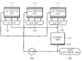
- FIG. 1 is a schematic diagram of a conventional fluid supply system used in manufacturing LCD devices.
- the baths 121 , 122 , and 123 are generally arranged in a structure where minimum pipelines are used so that a loss of pressure or heat of the fluid can be minimized.
- the size of the storage tank 130 should be large in that a huge amount of fluid can be stored therein.
- the storage tank 130 may include a heater (not shown). The heater adequately raises the temperature of the fluid so that the unit processes can be performed efficiently in the process units 111 , 112 , and 113 .
- the fluid stored in the storage tank 130 is supplied again to the process units 111 , 112 , and 113 in the baths via the pump 140 .
- the pipelines connecting the pump and the baths 121 , 122 , and 123 include valves (not shown), filters (not shown), and regulators (not shown).
- Fluid is supplied from the fluid supplement unit 150 in addition to the storage tank 130 . Since the fluid is adhered to the substrates and drained together with the substrates outside the baths 121 , 122 , and 123 during the processes, the fluid supplement unit 150 supplements the drained fluid.
- the fluid supplement unit 150 may also include a heater (not shown).
- FIG. 2 is a more detailed diagram of the conventional fluid supply system that is applied to cleaning equipment, in which only one bath 221 is represented.
- FIG. 2 simply and schematically shows the structure of a cleaning unit 211 placed in the bath 221 , as well as valves 261 , filters 262 , regulators 263 , and flow meters 264 included in pipelines, and may be different from the structure of a cleaning unit and the arrangements of pipelines used in actual cleaning equipment.
- the conventional fluid supplying system is characterized in that a bath is provided for each process unit and only one storage tank is used for a plurality of baths. Accordingly, the distance between the baths and the storage tank and that between the pump and baths are fairly long. Thus, the temperature and the pressure of fluid can be lowered while passing through the long pipelines.
- the body of the bath 221 used in the fluid supplying system is generally made of durable materials such as steel, namely, SUS metal or Polyvinyl Chloride (PVC), through welding or coupling since wet processes should be performed to remove organic or inorganic substances, metal ion surface films, corpuscles, or contaminants adhered on the surface of the LCD device.
- durable materials such as steel, namely, SUS metal or Polyvinyl Chloride (PVC)
- PVC Polyvinyl Chloride
- the body of the bath 221 is eroded by a strong acid fluid used in an wet etching process.
- the SUS metal is hardly used in the bath for etching process.
- the material of the body of bath 221 is PVC
- the body of the bath 221 is eroded by an organic solvent used in a stripping process. Since the body of the bath can be melted due to the organic solvent, the use of PVC is also restricted.
- the baths used for stripping, cleaning, etching, and developing are not compatible with each other. Further, use of new chemical fluids in the wet processes is restricted because the material of the bath should be firstly considered.
- a fluid supplying system for LCD manufacturing equipment which includes a bath united with storage tank including a process unit and a fluid storage tank united with the bath; a fluid supplement unit for supplementing fluid that is adhered to substrates within the process unit and discharged together with the substrates outside of the bath united with storage tank; a pump for supplying fluid stored in the bath united with storage tank and the fluid supplemented from the fluid supplement unit; and a plurality of pipelines for connecting the bath united with storage tank, including the process unit, and the fluid supplement unit to the pump.
- the LCD manufacturing equipment can be cleaning, etching, developing, or stripping equipment.
- the bath united with storage tank includes a first heater for heating the fluid and the fluid supplement unit includes a second heater for heating the fluid to be supplemented at a constant temperature.
- the pipelines for connecting the process unit to the pump include filters, valves, regulators, and flow meters.
- a wet processing bath for LCD manufacturing equipment which includes a bath body; a process unit included in the bath body, in which a predetermined process is performed; and an outlet for draining fluid within the bath body outside of the bath, wherein the bath body is made of a durable material and a chemically resistive material is coated on the surface of the durable material.
- the LCD manufacturing equipment can be cleaning, etching, developing, or stripping equipment.
- the chemically resistive material is Teflon and may be coated on one side or both sides of the durable material.
- a fluid supplying system for LCD manufacturing equipment which includes a bath united with storage tank including a process unit and a fluid storage tank united with the bath; a fluid supplement unit for supplementing fluid that is adhered to substrates within the process unit and drained together with the substrates outside of the bath united with storage tank; a pump for supplying fluid stored in the bath united with storage tank and the fluid supplemented from the fluid supplement unit; and a plurality of pipelines for connecting the bath united with storage tank, including the process unit, and the fluid supplement unit to the pump, wherein the bath united with storage tank includes a bath body; a process unit included in the bath body, in which a predetermined process is performed; and an outlet for draining fluid within the bath body outside of the bath, and the bath body is made of a durable material and a chemically resistive material coated on the surface of the durable material.
- the LCD manufacturing equipment can be cleaning, etching, developing, or stripping equipment.
- the chemically resistive material is Teflon and that the chemically resistive material is coated on one side or both sides of the durable material.
- FIG. 1 is a schematic diagram of a convention fluid supplying system for LCD manufacturing equipment
- FIG. 2 is a more detailed diagram of the conventional fluid supplying system
- FIG. 3 is a schematic diagram of a fluid supplying system according to the present invention.
- FIG. 4 is a more detailed diagram of the fluid supplying system shown in FIG. 3;
- FIG. 5 is a perspective view of a typical bath included in a fluid supplying system for LCD manufacturing equipment
- FIG. 6 is a cross-sectional view of the bath shown in FIG. 5;
- FIG. 7 is a partially enlarged cross-sectional view of the bath included in the fluid supplying system according to an embodiment of the present invention.
- FIG. 8 is a partially enlarged cross-sectional view of the bath included in the fluid supplying system according to another embodiment of the present invention.
- FIG. 3 is a schematic diagram of a fluid-supplying system according to the present invention
- FIG. 4 is a more detailed diagram of the fluid supplying system shown in FIG. 3.
- the fluid supplying system includes a bath united with storage tank 320 or 420 including a process unit 310 or 410 , a fluid supplement unit 350 or 450 , a pump 340 or 440 , and pipelines connecting the foregoing elements.
- a wet process, such as a cleaning process, for a glass substrate (not shown) is performed in the process unit 310 or 410 included in the bath united with storage tank 320 or 420 .
- the fluid used in the wet process is collected in the bath united with storage tank 320 or 420 .
- the bath according to the invention is characterized in that a fluid storage tank is united with the bath. Since an individual storage tank, i.e., the bath united with storage tank 320 or 420 , is provided for each process unit 310 or 410 , there is no need to provide a large storage tank as used in a conventional system. Further, while pipelines for connecting a bath and a storage tank have been used in the conventional system, such pipelines are no longer required according to the present invention. That is, comparing FIG. 4 with FIG. 2, it is understood that the structure of the fluid supplying system according to the present invention in FIG. 4 is simpler than that of the conventional system in FIG. 2.
- a first heater 465 is provided to the bath united with storage tank 420 .
- the temperature of the bath united with storage tank 420 is determined in consideration of thermal loss during the supply of the fluid.
- the process unit 310 or 410 is provided with the fluid collected and stored in the bath united with storage tank 320 or 420 and the fluid supplemented from the fluid supplement unit 350 or 450 via the pump 340 or 440 .
- a second heater (not shown) can be provided in the fluid supplement unit 350 or 450 to keep the supplementary fluid at an optimum process temperature.
- the pipelines connecting the pump 340 or 440 and the process unit 310 or 410 include valves 461 , a filter 462 , a regulator 463 , and/or a flow meter 464 .
- the distance from the pump 340 or 440 to the process unit 310 or 410 is very short since a bath united with storage tank 320 or 420 is individually provided for each process unit. Since the distance from the pump 340 or 440 to the process unit 310 or 410 is short, the number of connector elements of the pipelines, e.g., filters, valves, elbows, reducers, T's, etc., can be minimized. Accordingly, the loss of pressure due to friction within the pipelines can be minimized. Further, since thermal loss in the pipelines is reduced, costs can be saved.
- the amount of fluid supplemented by the fluid supplement unit 450 of cleaning equipment is generally about 0.5 liters per substrate. That is, fluid of about 0.5 liters is adhered to each substrate and discharged, together with each substrate, outwardly. Since the total amount of fluid supplemented by the fluid supplement unit 450 according to the present invention is smaller than the amount of fluid supplemented by a conventional fluid supplement unit, a much higher ratio of the fluid to the entire fluid can be achieved according to the present invention. According to the present invention, since a fairly large amount of clean fluid is continuously re-supplied and mixed with the existing fluid in the equipment, the opacity of the fluid does not increase beyond a certain level despite of the continuation of the processes. Therefore, it is possible to prevent operational errors in the processes and the occurrence of defective LCD devices due to the increase of the opacity of the fluid.
- the bath described below can be either a conventional independent bath separated from the storage tank or the above-described bath united with storage tank. That is, the body material of the bath is not limited to only those materials used for the bath united with storage tank according to the present invention, but can include the conventional materials used in the body of the conventional bath.
- FIG. 5 is a perspective view of a typical bath included in a fluid supplying system for LCD manufacturing equipment
- FIG. 6 is a cross-sectional view of the bath taken along line A-A′ of FIG. 5.
- the bath 500 used in a wet process for manufacturing LCD devices typically includes a body 510 , in which glass substrates for fabricating LCD devices are input and are subject to a wet process; a fluid supplying unit 520 mounted within the body 510 , which supplies chemical fluid into the body 510 ; and an outlet 530 through which the chemical fluid used in the process is discharged.
- a loading and conveying means 540 for loading and conveying the glass substrates for fabricating LCD devices can be mounted within the body 510 .
- the elements of the bath 500 i.e., the fluid supplying unit 520 , the loading and conveying means 540 , and the outlet 530 , form the process unit.
- the outlet 530 can be connected to a fluid storage tank (not shown) provided outside to collect the used chemical fluid, if necessary. If the bath united with storage tank is used as described above, the used chemical fluid is collected at the bottom of the bath.
- the glass substrates for fabricating LCD devices are moved into the body 510 via the loading and conveying means 540 and the thin film or photoresist on the surfaces of the glass substrates is cleaned, stripped, developed, or etched by the chemical fluid or the deionized water sprayed via the fluid supplying unit 520 .
- FIG. 7 is a partially enlarged cross-sectional view showing materials of the body of the bath included in the fluid supplying system according to an embodiment of the present invention.
- FIG. 8 shows a modification thereto.
- the body of the conventional bath has been made of a single durable material, such as steel or PVD
- the body of the bath according to the present invention is made of a durable material 512 with a chemically resistive material 514 coated thereon.
- the chemically resistive material may be a Teflon film. Since the Teflon film is a very high chemical resistive material that does not react with chemical fluid like organic solvent, the Teflon film can be widely used during wet processes regardless of the kind of chemical fluid.
- the body of the bath is made of the durable material 512 together with the chemically resistive material 514 , the bath according to the present invention can be compatibly used in any equipment, such as stripping, cleaning, etching, or developing equipment.
- the durable material 512 may be steel or PVC.
- the chemical resistive material 514 can be coated on either only the inner surface of the body of the bath where the chemical fluid contacts or both sides of the durable material 512 , as shown in FIG. 8, in consideration of the chemical fluid leaking out or the gases forming from the chemical fluid.
- the fluid storage tank is united with the bath for collecting fluid and the storage tank is individually provided to each bath, the size of the storage tank and the length between the storage tank and the process unit can be reduced and, as a result, the arrangements of pipelines can be simplified. Further, the loss of pressure and heat of the process fluid through the pipelines can be reduced and, therefore, costs can be saved.
- the fluid can be sufficiently provided even with a small pump. Moreover, since the opacity of the fluid can be maintained at a certain level, there is no need to exchange the entire amount of the fluid after completing certain processes.
- the body of the bath is coated with a high chemical resistive material, it is possible to prevent the durable material of the body of the bath from reacting with the chemical fluid used for wet processes.
- the wet processing bath can be compatibly used in any equipment, such as stripping, developing, etching, or cleaning equipment, in which wet processes are performed.
Abstract
Description
- This application claims the priority of Korean Patent Application No. 2002-22205, filed on Apr. 23, 2002, and Korean Patent Application No. 2002-22700, filed on Apr. 25, 2002, in the Korean Intellectual Property Office, the disclosure of which is incorporated herein in its entirety by reference.
- 1. Field of the Invention
- The present invention relates to a fluid supplying system for LCD (liquid crystal display) manufacturing equipment, and more particularly, to a wet processing bath for LCD manufacturing equipment and a fluid supplying system including the wet processing bath.
- 2. Description of the Related Art
- Recently, sizes of LCD panels have been becoming larger and resolutions thereof have been becoming higher. As technical problems concerning, e.g., higher contrast, wider viewing angle, etc., are being solved, conventional CRT (Cathode Ray Tube) devices are rapidly being replaced by LCD devices. Particularly, such a trend is accelerated in relation to the development of active matrix type TFT-LCD (Thin Film Transistor Liquid Crystal Display) devices and wider applications thereof. The active matrix type TFT-LCD is characterized in that switching elements called TFT's are formed in correspondence to each pixel and the pixels are individually controlled.
- Generally, glass is used as a substrate material in a process for fabricating transistors formed in correspondence to each pixel of a TFT-LCD device, i.e., a thin film transistor fabrication process. Since the melting point of glass is relatively low, a processing temperature of the thin film transistor fabrication process is limited to the range of 300 to 500° C. Further, in order to embody a circuit on the glass substrate, unit processes of a typical semiconductor fabrication process are applied to the thin film transistor fabrication process. Therefore, lots of wet processes using fluid are adapted to the thin film transistor fabrication process. In the wet processes, such as cleaning, stripping, wet etching, or developing, a fluid such as a chemical solution or deionized water is used.
- FIG. 1 is a schematic diagram of a conventional fluid supply system used in manufacturing LCD devices.
- Referring to FIG. 1, the fluid supplying system includes a plurality of
baths storage tank 130, apump 140, afluid supplement unit 150, and pipelines (not shown) for connecting the foregoing elements. Unit process, e.g., cleaning, etching, or developing, is performed in thebaths baths storage tank 130 and thepump 140 via the pipelines. - Although three
baths pump 130. While the size of thestorage tank 130 and the arrangement of the baths are determined according to the number of thebaths baths - The fluid is supplied to the
process units pump 140, and the used fluid is collected in thebaths baths baths storage tank 130 via the pipelines. During this process, some of the residual materials can be filtered. - As shown in FIG. 1, since a
single storage tank 130 is used in connection with a plurality ofbaths storage tank 130 should be large in that a huge amount of fluid can be stored therein. Typically, thestorage tank 130 may include a heater (not shown). The heater adequately raises the temperature of the fluid so that the unit processes can be performed efficiently in theprocess units - The fluid stored in the
storage tank 130 is supplied again to theprocess units pump 140. The pipelines connecting the pump and thebaths fluid supplement unit 150 in addition to thestorage tank 130. Since the fluid is adhered to the substrates and drained together with the substrates outside thebaths fluid supplement unit 150 supplements the drained fluid. Thefluid supplement unit 150 may also include a heater (not shown). - FIG. 2 is a more detailed diagram of the conventional fluid supply system that is applied to cleaning equipment, in which only one
bath 221 is represented. FIG. 2 simply and schematically shows the structure of acleaning unit 211 placed in thebath 221, as well asvalves 261,filters 262,regulators 263, andflow meters 264 included in pipelines, and may be different from the structure of a cleaning unit and the arrangements of pipelines used in actual cleaning equipment. - Apparent from FIGS. 1 and 2, the conventional fluid supplying system is characterized in that a bath is provided for each process unit and only one storage tank is used for a plurality of baths. Accordingly, the distance between the baths and the storage tank and that between the pump and baths are fairly long. Thus, the temperature and the pressure of fluid can be lowered while passing through the long pipelines.
- Due to the thermal loss in the conventional fluid supplying system, additional costs are required in equipping large-capacity pumps to reduce the thermal loss. Further, it is hard to supply fluid at an optimum temperature. In addition, since a great amount of fluid should be supplied to each bath, a pump having a large capacity is required.
- Furthermore, long pipelines are required for connecting each element of the conventional fluid supplying system, and the arrangements of the pipelines and the structure of the system are very complex. For example, numerous connecting elements, such as filers, valves, elbows, reducers, T's, etc., should be used and be arranged in a complicated manner. Particularly, in a case where the processing fluid is a highly toxic chemical, such as hydrochloric or nitric acid, the connecting elements used in the pipelines are very expensive, and accordingly, the cost and expenses for manufacturing and maintaining the fluid supplying system are increased.
- Moreover, in the conventional fluid supplying system, the amount of fluid supplemented from the fluid supplement unit is very small in comparison to the amount of the fluid used in the process units. If the amount of the processing fluid is great, it is difficult to prevent the gradual increase in the opacity of the fluid even though clean fluid is supplemented from the outside. If the opacity of the fluid increases, the substrates may be contaminated and, thus, the production yield of the LCD devices will be decreased. In order to prevent the contamination of the substrates and the decrease of the production yield, it is required to periodically replace all of the fluid stored in the storage tank with fresh fluid.
- Meanwhile, the body of the
bath 221 used in the fluid supplying system is generally made of durable materials such as steel, namely, SUS metal or Polyvinyl Chloride (PVC), through welding or coupling since wet processes should be performed to remove organic or inorganic substances, metal ion surface films, corpuscles, or contaminants adhered on the surface of the LCD device. - In order to reduce the process time, the concentration of the chemical fluid used in the wet processes for manufacturing the LCD devices is becoming higher. However, due to the high concentration of the chemical fluid, the surface of the body of the
bath 221 is easily damaged. - For example, in a case where the material of the body of
bath 221 is steel, namely, as SUS metal, the body of thebath 221 is eroded by a strong acid fluid used in an wet etching process. Thus, the SUS metal is hardly used in the bath for etching process. Further, in a case where the material of the body ofbath 221 is PVC, the body of thebath 221 is eroded by an organic solvent used in a stripping process. Since the body of the bath can be melted due to the organic solvent, the use of PVC is also restricted. - That is, the baths used for stripping, cleaning, etching, and developing are not compatible with each other. Further, use of new chemical fluids in the wet processes is restricted because the material of the bath should be firstly considered.
- It is an aspect of the present invention to provide a fluid supplying system for LCD manufacturing equipment, which prevents losses of heat and pressure, operates with a small pump, requires lower manufacturing costs and maintenance expenses, and is small in size.
- According to the aspect of the present invention, there is provided a fluid supplying system for LCD manufacturing equipment, which includes a bath united with storage tank including a process unit and a fluid storage tank united with the bath; a fluid supplement unit for supplementing fluid that is adhered to substrates within the process unit and discharged together with the substrates outside of the bath united with storage tank; a pump for supplying fluid stored in the bath united with storage tank and the fluid supplemented from the fluid supplement unit; and a plurality of pipelines for connecting the bath united with storage tank, including the process unit, and the fluid supplement unit to the pump. Here, the LCD manufacturing equipment can be cleaning, etching, developing, or stripping equipment.
- Preferably, the bath united with storage tank includes a first heater for heating the fluid and the fluid supplement unit includes a second heater for heating the fluid to be supplemented at a constant temperature. Further, the pipelines for connecting the process unit to the pump include filters, valves, regulators, and flow meters.
- It is another aspect of the present invention to provide a wet processing bath for LCD manufacturing equipment, which is not significantly influenced by chemical fluid used in wet processes and which can be compatibly used in stripping, cleaning, etching, and developing equipment.
- According to another aspect of the present invention, there is provided a wet processing bath for LCD manufacturing equipment, which includes a bath body; a process unit included in the bath body, in which a predetermined process is performed; and an outlet for draining fluid within the bath body outside of the bath, wherein the bath body is made of a durable material and a chemically resistive material is coated on the surface of the durable material. Here, the LCD manufacturing equipment can be cleaning, etching, developing, or stripping equipment.
- Preferably, the chemically resistive material is Teflon and may be coated on one side or both sides of the durable material.
- According to still another aspect of the present invention, there is provided a fluid supplying system for LCD manufacturing equipment, which includes a bath united with storage tank including a process unit and a fluid storage tank united with the bath; a fluid supplement unit for supplementing fluid that is adhered to substrates within the process unit and drained together with the substrates outside of the bath united with storage tank; a pump for supplying fluid stored in the bath united with storage tank and the fluid supplemented from the fluid supplement unit; and a plurality of pipelines for connecting the bath united with storage tank, including the process unit, and the fluid supplement unit to the pump, wherein the bath united with storage tank includes a bath body; a process unit included in the bath body, in which a predetermined process is performed; and an outlet for draining fluid within the bath body outside of the bath, and the bath body is made of a durable material and a chemically resistive material coated on the surface of the durable material. Here, the LCD manufacturing equipment can be cleaning, etching, developing, or stripping equipment.
- Preferably, the bath united with storage tank includes a first heater for heating the fluid and the fluid supplement unit includes a second heater for heating the fluid to be supplemented at a constant temperature. Further, the pipelines for connecting the process unit to the pump include filters, valves, regulators, and flow meters.
- It is also preferable that the chemically resistive material is Teflon and that the chemically resistive material is coated on one side or both sides of the durable material.
- The above and other aspects and advantages of the present invention will become more apparent by describing in detail preferred embodiments thereof with reference to the attached drawings in which:
- FIG. 1 is a schematic diagram of a convention fluid supplying system for LCD manufacturing equipment;
- FIG. 2 is a more detailed diagram of the conventional fluid supplying system;
- FIG. 3 is a schematic diagram of a fluid supplying system according to the present invention;
- FIG. 4 is a more detailed diagram of the fluid supplying system shown in FIG. 3;
- FIG. 5 is a perspective view of a typical bath included in a fluid supplying system for LCD manufacturing equipment;
- FIG. 6 is a cross-sectional view of the bath shown in FIG. 5;
- FIG. 7 is a partially enlarged cross-sectional view of the bath included in the fluid supplying system according to an embodiment of the present invention; and
- FIG. 8 is a partially enlarged cross-sectional view of the bath included in the fluid supplying system according to another embodiment of the present invention.
- Hereinafter, the present invention will be described more fully with reference to the accompanied drawings in which preferred embodiments of the invention are shown. This invention may, however, be embodied in many different forms and should not be construed as being limited to the embodiments set forth herein. Rather, these embodiments are provided so that this disclosure will be thorough and complete and will fully convey the scope of the invention to those skilled in the art. In the drawings, the forms of the elements are exaggerated for clarity. To facilitate understanding, identical reference numerals have been used, where possible, to designate identical elements that are common to the figures.
- FIG. 3 is a schematic diagram of a fluid-supplying system according to the present invention, and FIG. 4 is a more detailed diagram of the fluid supplying system shown in FIG. 3.
- Referring to FIGS. 3 and 4, the fluid supplying system includes a bath united with
storage tank process unit fluid supplement unit pump - A wet process, such as a cleaning process, for a glass substrate (not shown) is performed in the
process unit storage tank storage tank storage tank process unit - In order to constantly keep the fluid at an optimum temperature, a
first heater 465 is provided to the bath united withstorage tank 420. The temperature of the bath united withstorage tank 420 is determined in consideration of thermal loss during the supply of the fluid. - The
process unit storage tank fluid supplement unit pump fluid supplement unit pump process unit valves 461, afilter 462, aregulator 463, and/or aflow meter 464. - As shown in FIGS. 3 and 4, in the fluid supplying system according to the present invention, the distance from the
pump process unit storage tank pump process unit - The amount of fluid supplemented by the
fluid supplement unit 450 of cleaning equipment is generally about 0.5 liters per substrate. That is, fluid of about 0.5 liters is adhered to each substrate and discharged, together with each substrate, outwardly. Since the total amount of fluid supplemented by thefluid supplement unit 450 according to the present invention is smaller than the amount of fluid supplemented by a conventional fluid supplement unit, a much higher ratio of the fluid to the entire fluid can be achieved according to the present invention. According to the present invention, since a fairly large amount of clean fluid is continuously re-supplied and mixed with the existing fluid in the equipment, the opacity of the fluid does not increase beyond a certain level despite of the continuation of the processes. Therefore, it is possible to prevent operational errors in the processes and the occurrence of defective LCD devices due to the increase of the opacity of the fluid. - Now, a bath included in the fluid supplying system for LCD manufacturing equipment will be described. The bath described below can be either a conventional independent bath separated from the storage tank or the above-described bath united with storage tank. That is, the body material of the bath is not limited to only those materials used for the bath united with storage tank according to the present invention, but can include the conventional materials used in the body of the conventional bath.
- FIG. 5 is a perspective view of a typical bath included in a fluid supplying system for LCD manufacturing equipment, and FIG. 6 is a cross-sectional view of the bath taken along line A-A′ of FIG. 5.
- Referring to FIGS. 5 and 6, the
bath 500 used in a wet process for manufacturing LCD devices typically includes abody 510, in which glass substrates for fabricating LCD devices are input and are subject to a wet process; afluid supplying unit 520 mounted within thebody 510, which supplies chemical fluid into thebody 510; and anoutlet 530 through which the chemical fluid used in the process is discharged. If necessary, a loading and conveyingmeans 540 for loading and conveying the glass substrates for fabricating LCD devices can be mounted within thebody 510. Except for thebody 510, according to the above-described embodiment, the elements of thebath 500, i.e., thefluid supplying unit 520, the loading and conveyingmeans 540, and theoutlet 530, form the process unit. - Not only can chemical fluid that is used in the wet process be supplied, but deionized water can be sprayed via the
fluid supplying unit 520. Further, theoutlet 530 can be connected to a fluid storage tank (not shown) provided outside to collect the used chemical fluid, if necessary. If the bath united with storage tank is used as described above, the used chemical fluid is collected at the bottom of the bath. The glass substrates for fabricating LCD devices are moved into thebody 510 via the loading and conveyingmeans 540 and the thin film or photoresist on the surfaces of the glass substrates is cleaned, stripped, developed, or etched by the chemical fluid or the deionized water sprayed via thefluid supplying unit 520. - FIG. 7 is a partially enlarged cross-sectional view showing materials of the body of the bath included in the fluid supplying system according to an embodiment of the present invention; and FIG. 8 shows a modification thereto.
- While the body of the conventional bath has been made of a single durable material, such as steel or PVD, the body of the bath according to the present invention is made of a
durable material 512 with a chemicallyresistive material 514 coated thereon. For example, the chemically resistive material may be a Teflon film. Since the Teflon film is a very high chemical resistive material that does not react with chemical fluid like organic solvent, the Teflon film can be widely used during wet processes regardless of the kind of chemical fluid. Since the body of the bath is made of thedurable material 512 together with the chemicallyresistive material 514, the bath according to the present invention can be compatibly used in any equipment, such as stripping, cleaning, etching, or developing equipment. Thedurable material 512 may be steel or PVC. - Further, the chemical
resistive material 514 can be coated on either only the inner surface of the body of the bath where the chemical fluid contacts or both sides of thedurable material 512, as shown in FIG. 8, in consideration of the chemical fluid leaking out or the gases forming from the chemical fluid. - As described above, according to the present invention, since the fluid storage tank is united with the bath for collecting fluid and the storage tank is individually provided to each bath, the size of the storage tank and the length between the storage tank and the process unit can be reduced and, as a result, the arrangements of pipelines can be simplified. Further, the loss of pressure and heat of the process fluid through the pipelines can be reduced and, therefore, costs can be saved. In addition, the fluid can be sufficiently provided even with a small pump. Moreover, since the opacity of the fluid can be maintained at a certain level, there is no need to exchange the entire amount of the fluid after completing certain processes.
- Meanwhile, since the body of the bath is coated with a high chemical resistive material, it is possible to prevent the durable material of the body of the bath from reacting with the chemical fluid used for wet processes. Further, the wet processing bath can be compatibly used in any equipment, such as stripping, developing, etching, or cleaning equipment, in which wet processes are performed.
- While the present invention has been particularly shown and described with reference to preferred embodiments thereof, it will be understood by those of ordinary skill in the art that various changes in form and details may be made therein without departing from the spirit and scope of the present invention as defined by the appended claims.
Claims (16)
Applications Claiming Priority (6)
| Application Number | Priority Date | Filing Date | Title |
|---|---|---|---|
| KR10-2002-0022205 | 2002-04-23 | ||
| KR2002-22205 | 2002-04-23 | ||
| KR1020020022205A KR20030083501A (en) | 2002-04-23 | 2002-04-23 | Fluid supply device for the manufacturing apparatus of liquid crystal display devices |
| KR1020020022700A KR20030084152A (en) | 2002-04-25 | 2002-04-25 | Bath for wet processing of Liquid Crystal Display device |
| KR10-2002-0022700 | 2002-04-25 | ||
| KR2002-22700 | 2002-04-25 |
Publications (2)
| Publication Number | Publication Date |
|---|---|
| US20030196719A1 true US20030196719A1 (en) | 2003-10-23 |
| US6817387B2 US6817387B2 (en) | 2004-11-16 |
Family
ID=29218043
Family Applications (1)
| Application Number | Title | Priority Date | Filing Date |
|---|---|---|---|
| US10/413,557 Expired - Lifetime US6817387B2 (en) | 2002-04-23 | 2003-04-15 | Wet processing bath and fluid supplying system for liquid crystal display manufacturing equipment |
Country Status (3)
| Country | Link |
|---|---|
| US (1) | US6817387B2 (en) |
| CN (1) | CN100394554C (en) |
| TW (1) | TWI270626B (en) |
Cited By (3)
| Publication number | Priority date | Publication date | Assignee | Title |
|---|---|---|---|---|
| CN100426069C (en) * | 2005-10-26 | 2008-10-15 | 拓志光机电股份有限公司 | Pressure debubble furnace and its application method |
| CN103163002A (en) * | 2013-04-11 | 2013-06-19 | 王刚平 | Immunohistochemical wet box |
| US20170268114A1 (en) * | 2014-12-02 | 2017-09-21 | Cmi Uvk Gmbh | Method and system of treating a stainless steel strip, especially for a pickling treatment |
Families Citing this family (2)
| Publication number | Priority date | Publication date | Assignee | Title |
|---|---|---|---|---|
| CN100376936C (en) * | 2004-05-28 | 2008-03-26 | 鸿富锦精密工业(深圳)有限公司 | LCD production system and control method thereof |
| KR102303243B1 (en) * | 2015-01-14 | 2021-09-17 | 삼성디스플레이 주식회사 | Apparatus and method for manufacturing display apparatus |
Citations (2)
| Publication number | Priority date | Publication date | Assignee | Title |
|---|---|---|---|---|
| US6461437B1 (en) * | 2000-01-26 | 2002-10-08 | Mitsubishi Denki Kabushiki Kaisha | Apparatus used for fabricating liquid crystal device and method of fabricating the same |
| US6551488B1 (en) * | 1999-04-08 | 2003-04-22 | Applied Materials, Inc. | Segmenting of processing system into wet and dry areas |
Family Cites Families (4)
| Publication number | Priority date | Publication date | Assignee | Title |
|---|---|---|---|---|
| JPH0810685B2 (en) * | 1990-05-11 | 1996-01-31 | 富士通株式会社 | Substrate wet processing equipment |
| JPH04171934A (en) * | 1990-11-06 | 1992-06-19 | Nec Yamaguchi Ltd | Wet type processing equipment for semiconductor |
| KR100226548B1 (en) * | 1996-12-24 | 1999-10-15 | 김영환 | Wet treating apparatus of semiconductor wafer |
| JP2002509800A (en) * | 1998-03-30 | 2002-04-02 | ザ リージェンツ オブ ザ ユニバーシティ オブ カリフォルニア | Apparatus and method for delivering pulsating fluid |
-
2003
- 2003-04-10 TW TW092108205A patent/TWI270626B/en not_active IP Right Cessation
- 2003-04-15 US US10/413,557 patent/US6817387B2/en not_active Expired - Lifetime
- 2003-04-21 CN CNB031222137A patent/CN100394554C/en not_active Expired - Lifetime
Patent Citations (2)
| Publication number | Priority date | Publication date | Assignee | Title |
|---|---|---|---|---|
| US6551488B1 (en) * | 1999-04-08 | 2003-04-22 | Applied Materials, Inc. | Segmenting of processing system into wet and dry areas |
| US6461437B1 (en) * | 2000-01-26 | 2002-10-08 | Mitsubishi Denki Kabushiki Kaisha | Apparatus used for fabricating liquid crystal device and method of fabricating the same |
Cited By (3)
| Publication number | Priority date | Publication date | Assignee | Title |
|---|---|---|---|---|
| CN100426069C (en) * | 2005-10-26 | 2008-10-15 | 拓志光机电股份有限公司 | Pressure debubble furnace and its application method |
| CN103163002A (en) * | 2013-04-11 | 2013-06-19 | 王刚平 | Immunohistochemical wet box |
| US20170268114A1 (en) * | 2014-12-02 | 2017-09-21 | Cmi Uvk Gmbh | Method and system of treating a stainless steel strip, especially for a pickling treatment |
Also Published As
| Publication number | Publication date |
|---|---|
| CN1453607A (en) | 2003-11-05 |
| TWI270626B (en) | 2007-01-11 |
| TW200305699A (en) | 2003-11-01 |
| US6817387B2 (en) | 2004-11-16 |
| CN100394554C (en) | 2008-06-11 |
Similar Documents
| Publication | Publication Date | Title |
|---|---|---|
| JP4989370B2 (en) | Nozzle and substrate processing apparatus having the same | |
| JP4738033B2 (en) | Substrate processing equipment | |
| JP2000120530A (en) | Chemicals supply method and device | |
| US6155275A (en) | Substrate processing unit and substrate processing apparatus using the same | |
| CN100543537C (en) | Substrate processing apparatus and use its substrate processing method using same | |
| US8298341B2 (en) | Removal of metal contaminant deposited on quartz member of vertical heat processing apparatus | |
| JP2007123393A (en) | Substrate-treating device | |
| US6817387B2 (en) | Wet processing bath and fluid supplying system for liquid crystal display manufacturing equipment | |
| WO2011034841A2 (en) | Method and apparatus for showerhead cleaning | |
| JP2007273791A (en) | Substrate processing apparatus and method | |
| US7790052B2 (en) | Substrate receiving method | |
| WO2006041028A1 (en) | Treatment liquid supply device | |
| EP1843208A2 (en) | Photoresist stripping apparatus, method of recycling photoresist stripper, and method of manufacturing thin film transistor array panel using the photoresist stripping apparatus | |
| KR101252481B1 (en) | In-line apparatus for developing having a cleaning device and method of fabricating liquid crystal display device using thereof | |
| KR20090015413A (en) | Apparatus for cleaning slit nozzle used in manufacturing flat panal display devices | |
| KR20100061035A (en) | Apparatus and method for treating substrate | |
| KR100635112B1 (en) | Fluid supply device for the manufacturing apparatus of liquid crystal display devices | |
| KR102278079B1 (en) | Apparatus and Method for treating substrate | |
| KR20070034890A (en) | Bubble prevention device of chemical tank | |
| KR100574567B1 (en) | Fluid supply device for the manufacturing apparatus of liquid crystal display devices | |
| JP2588960Y2 (en) | Substrate processing equipment | |
| US7393431B2 (en) | Bubble plate for etching and etching apparatus using the same | |
| JP2599800Y2 (en) | Substrate cleaning device | |
| KR20080078299A (en) | Apparatus for processing substrate | |
| KR100489623B1 (en) | Processing equipment for a substrate of liquid crystal display device |
Legal Events
| Date | Code | Title | Description |
|---|---|---|---|
| AS | Assignment |
Owner name: DISPLAY MANUFACTURING SERVICE CO., LTD., KOREA, RE Free format text: ASSIGNMENT OF ASSIGNORS INTEREST;ASSIGNORS:PARK, YONG-SEOK;KIM, SANG-HO;LEE, SOK-JOO;REEL/FRAME:013981/0561 Effective date: 20030303 |
|
| STCF | Information on status: patent grant |
Free format text: PATENTED CASE |
|
| FEPP | Fee payment procedure |
Free format text: PAYOR NUMBER ASSIGNED (ORIGINAL EVENT CODE: ASPN); ENTITY STATUS OF PATENT OWNER: SMALL ENTITY |
|
| FPAY | Fee payment |
Year of fee payment: 4 |
|
| FEPP | Fee payment procedure |
Free format text: PAYOR NUMBER ASSIGNED (ORIGINAL EVENT CODE: ASPN); ENTITY STATUS OF PATENT OWNER: SMALL ENTITY Free format text: PAYER NUMBER DE-ASSIGNED (ORIGINAL EVENT CODE: RMPN); ENTITY STATUS OF PATENT OWNER: SMALL ENTITY |
|
| FPAY | Fee payment |
Year of fee payment: 8 |
|
| FPAY | Fee payment |
Year of fee payment: 12 |