US20030197845A1 - Active damping apparatus, exposure apparatus and device manufacturing method - Google Patents
Active damping apparatus, exposure apparatus and device manufacturing method Download PDFInfo
- Publication number
- US20030197845A1 US20030197845A1 US10/412,315 US41231503A US2003197845A1 US 20030197845 A1 US20030197845 A1 US 20030197845A1 US 41231503 A US41231503 A US 41231503A US 2003197845 A1 US2003197845 A1 US 2003197845A1
- Authority
- US
- United States
- Prior art keywords
- stage
- counter
- mass
- isolation table
- switch
- Prior art date
- Legal status (The legal status is an assumption and is not a legal conclusion. Google has not performed a legal analysis and makes no representation as to the accuracy of the status listed.)
- Granted
Links
- 238000013016 damping Methods 0.000 title claims abstract description 55
- 238000004519 manufacturing process Methods 0.000 title claims abstract description 16
- 238000002955 isolation Methods 0.000 claims abstract description 70
- 238000006243 chemical reaction Methods 0.000 claims abstract description 15
- 239000000758 substrate Substances 0.000 claims description 12
- 230000004044 response Effects 0.000 claims description 9
- 238000012546 transfer Methods 0.000 claims description 6
- 230000003287 optical effect Effects 0.000 claims description 4
- 239000003795 chemical substances by application Substances 0.000 claims description 2
- 239000011248 coating agent Substances 0.000 claims description 2
- 238000000576 coating method Methods 0.000 claims description 2
- 239000004065 semiconductor Substances 0.000 abstract description 13
- 238000006073 displacement reaction Methods 0.000 description 31
- 238000010586 diagram Methods 0.000 description 17
- 230000001133 acceleration Effects 0.000 description 16
- 238000000034 method Methods 0.000 description 9
- 230000008569 process Effects 0.000 description 9
- 238000001514 detection method Methods 0.000 description 3
- 238000012545 processing Methods 0.000 description 3
- 238000005530 etching Methods 0.000 description 2
- 150000002500 ions Chemical class 0.000 description 2
- 239000011159 matrix material Substances 0.000 description 2
- 238000013459 approach Methods 0.000 description 1
- 230000015572 biosynthetic process Effects 0.000 description 1
- 230000008859 change Effects 0.000 description 1
- 238000013461 design Methods 0.000 description 1
- 238000011161 development Methods 0.000 description 1
- 230000000694 effects Effects 0.000 description 1
- 239000012530 fluid Substances 0.000 description 1
- 230000005484 gravity Effects 0.000 description 1
- 238000005286 illumination Methods 0.000 description 1
- 238000002347 injection Methods 0.000 description 1
- 239000007924 injection Substances 0.000 description 1
- 238000007689 inspection Methods 0.000 description 1
- 238000009413 insulation Methods 0.000 description 1
- 238000001459 lithography Methods 0.000 description 1
- 239000000463 material Substances 0.000 description 1
- 238000012986 modification Methods 0.000 description 1
- 230000004048 modification Effects 0.000 description 1
- 230000003647 oxidation Effects 0.000 description 1
- 238000007254 oxidation reaction Methods 0.000 description 1
- 238000004806 packaging method and process Methods 0.000 description 1
- 239000003504 photosensitizing agent Substances 0.000 description 1
- 238000012805 post-processing Methods 0.000 description 1
- 238000007781 pre-processing Methods 0.000 description 1
- 230000000644 propagated effect Effects 0.000 description 1
- 238000007789 sealing Methods 0.000 description 1
- 229910052710 silicon Inorganic materials 0.000 description 1
- 239000010703 silicon Substances 0.000 description 1
- 238000012360 testing method Methods 0.000 description 1
Images


Classifications
-
- G—PHYSICS
- G03—PHOTOGRAPHY; CINEMATOGRAPHY; ANALOGOUS TECHNIQUES USING WAVES OTHER THAN OPTICAL WAVES; ELECTROGRAPHY; HOLOGRAPHY
- G03F—PHOTOMECHANICAL PRODUCTION OF TEXTURED OR PATTERNED SURFACES, e.g. FOR PRINTING, FOR PROCESSING OF SEMICONDUCTOR DEVICES; MATERIALS THEREFOR; ORIGINALS THEREFOR; APPARATUS SPECIALLY ADAPTED THEREFOR
- G03F7/00—Photomechanical, e.g. photolithographic, production of textured or patterned surfaces, e.g. printing surfaces; Materials therefor, e.g. comprising photoresists; Apparatus specially adapted therefor
- G03F7/70—Microphotolithographic exposure; Apparatus therefor
- G03F7/70691—Handling of masks or workpieces
- G03F7/70766—Reaction force control means, e.g. countermass
-
- G—PHYSICS
- G03—PHOTOGRAPHY; CINEMATOGRAPHY; ANALOGOUS TECHNIQUES USING WAVES OTHER THAN OPTICAL WAVES; ELECTROGRAPHY; HOLOGRAPHY
- G03F—PHOTOMECHANICAL PRODUCTION OF TEXTURED OR PATTERNED SURFACES, e.g. FOR PRINTING, FOR PROCESSING OF SEMICONDUCTOR DEVICES; MATERIALS THEREFOR; ORIGINALS THEREFOR; APPARATUS SPECIALLY ADAPTED THEREFOR
- G03F7/00—Photomechanical, e.g. photolithographic, production of textured or patterned surfaces, e.g. printing surfaces; Materials therefor, e.g. comprising photoresists; Apparatus specially adapted therefor
- G03F7/70—Microphotolithographic exposure; Apparatus therefor
- G03F7/70691—Handling of masks or workpieces
- G03F7/70716—Stages
- G03F7/70725—Stages control
-
- G—PHYSICS
- G03—PHOTOGRAPHY; CINEMATOGRAPHY; ANALOGOUS TECHNIQUES USING WAVES OTHER THAN OPTICAL WAVES; ELECTROGRAPHY; HOLOGRAPHY
- G03F—PHOTOMECHANICAL PRODUCTION OF TEXTURED OR PATTERNED SURFACES, e.g. FOR PRINTING, FOR PROCESSING OF SEMICONDUCTOR DEVICES; MATERIALS THEREFOR; ORIGINALS THEREFOR; APPARATUS SPECIALLY ADAPTED THEREFOR
- G03F7/00—Photomechanical, e.g. photolithographic, production of textured or patterned surfaces, e.g. printing surfaces; Materials therefor, e.g. comprising photoresists; Apparatus specially adapted therefor
- G03F7/70—Microphotolithographic exposure; Apparatus therefor
- G03F7/708—Construction of apparatus, e.g. environment aspects, hygiene aspects or materials
- G03F7/70808—Construction details, e.g. housing, load-lock, seals or windows for passing light in or out of apparatus
- G03F7/70833—Mounting of optical systems, e.g. mounting of illumination system, projection system or stage systems on base-plate or ground
-
- G—PHYSICS
- G03—PHOTOGRAPHY; CINEMATOGRAPHY; ANALOGOUS TECHNIQUES USING WAVES OTHER THAN OPTICAL WAVES; ELECTROGRAPHY; HOLOGRAPHY
- G03F—PHOTOMECHANICAL PRODUCTION OF TEXTURED OR PATTERNED SURFACES, e.g. FOR PRINTING, FOR PROCESSING OF SEMICONDUCTOR DEVICES; MATERIALS THEREFOR; ORIGINALS THEREFOR; APPARATUS SPECIALLY ADAPTED THEREFOR
- G03F7/00—Photomechanical, e.g. photolithographic, production of textured or patterned surfaces, e.g. printing surfaces; Materials therefor, e.g. comprising photoresists; Apparatus specially adapted therefor
- G03F7/70—Microphotolithographic exposure; Apparatus therefor
- G03F7/708—Construction of apparatus, e.g. environment aspects, hygiene aspects or materials
- G03F7/70858—Environment aspects, e.g. pressure of beam-path gas, temperature
- G03F7/709—Vibration, e.g. vibration detection, compensation, suppression or isolation
Definitions
- the present invention relates to an improved active damping apparatus, an exposure apparatus and a device manufacturing method, and more particularly, to an active damping apparatus used in an exposure apparatus for imprinting a reticle circuit pattern onto a semiconductor wafer as well as a device manufacturing method employing the exposure apparatus equipped with the active damping apparatus for the manufacture of semiconductor devices.
- the XY stage is mounted atop a vibration-free device.
- these vibration-free devices are of two types: passive vibration-absorbing systems, using air springs, coil springs, vibration-proof rubber or the like to attenuate vibration, and active vibration-damping systems that drive an actuator such as a voice coil motor.
- vibration-free devices equipped with the passive vibration-absorbing systems described above are unable to effectively attenuate vibrations generated by the movement of the XY stage itself.
- the passive vibration-absorbing systems described above must strike a good balance between insulation from vibrations propagated through the floor of the apparatus, which is to say vibration-free performance, and the ability to suppress vibration due to movement of the XY stage itself, that is, damping performance.
- FIG. 1 An example of the structure of a conventional active damping device is shown in FIG. 1.
- the active damping device shown here is designed so that three separate control units, consisting of controllers 31 - 41 for air spring supports 1 , 8 , controllers for the stage 18 - 22 , and counter-mass drive controllers 25 - 29 , operate independently.
- controllers 31 - 41 for air spring supports 1 , 8 controllers for the stage 18 - 22
- counter-mass drive controllers 25 - 29 operate independently.
- a direction in which a stage 16 is driven defines the X axis
- a direction vertical thereto is the Z axis
- a direction through the center of gravity of an isolation table 15 orthogonal to a direction of movement of the stage 16 is the Y axis
- an axis of rotation around the y axis is the _Y axis.
- the isolation table 15 which mounts the stage 16 and a counter-mass 23 , is supported by air spring supports 1 , 8 .
- the air spring supports 1 , 8 have air springs 3 , 10 , pressurized mechanical springs 5 , 12 , and viscosity elements 6 , 13 for attenuating viscosity in order to eliminate vibration from the floor.
- Servo-valves 2 , 9 control the supply and exhaust of air that is the fluid body that operates the air springs 3 , 10 . Movement of the air springs is monitored by position sensors 4 , 11 so as to measure changes in the position of the isolation table 15 .
- the detection readings from the position sensors 4 and 11 are input to displacement amplifiers 30 and 31 , respectively, and from the displacement amplifiers 30 and 31 are input to a displacement analyzer 32 .
- the displacement analyzer 32 then analyzes the readings into a vertical (Z axis) displacement component and a rotational displacement (_Y) component about the Y axis using calculations on a 2 ⁇ 2 matrix having as its elements the displacement and rotation (angle of rotation) of the air springs 3 , 10 , with the vertical and rotational displacement components forming negative feedback for calculating a deviation signal to be input to PI compensators 33 , 34 .
- acceleration readings of the isolation table 15 measured by acceleration sensors 7 , 14 are input to an acceleration analyzer 37 after having been fed respectively through each of filters 35 and 36 , which have predetermined appropriate gain and time constants.
- the acceleration analyzer 37 then analyzes the acceleration readings into a vertical (Z axis) acceleration component and a rotational (_Y axis) component about the Y axis, using the two inputs from the acceleration sensors 7 , 14 , with the vertical and rotational displacement component forming negative feedback for calculating a deviation signal to be input to a thrust allocator 38 .
- a target position setting unit 41 sets a target position for the displacement of the isolation table 15 in the vertical and rotational directions, with a deviation signal between the set target value and the displacement analyzer 32 output signal being input to the PI compensators 33 , 34 .
- the deviation signal between the PI compensators 33 , 34 output signals and the acceleration analyzer 37 output signal are then input to the thrust allocator 38 .
- the thrust allocator 38 then allocates command values for controlling the air springs in the vertical (Z axis) direction and the rotational (_Y) direction about the Y axis as drive command values for the air springs 3 and 10 .
- the drive command values so allocated are each converted into drive currents by the amplifiers 39 and 40 and by the servo valves 2 and 9 , with the opening and closing of the servo valves 2 and 9 adjusting the pressure inside the air springs 3 and 10 so that the isolation table 15 can be held at a desired position set by the target position setting unit 41 without steady-state deviation.
- the PI compensators 33 and 34 each act as displacement control compensators in the vertical direction (that is, along the Z axis) and in the rotational direction about the Y axis (that is, along the _Y axis), respectively.
- the “P” element of the PI compensator proportionally calculating the extent of adjustment, the “I” element compensating so as to perform integral calculations with respect to-the extent of adjustment.)
- the foregoing comprises control of the air spring supports 1 , 8 for the isolation table 15 .
- Position readings from a position sensor 17 that measures horizontal displacement of the stage 16 mounted atop the isolation table 15 are input to a displacement amplifier 18 .
- a deviation signal between the output signals from the displacement amplifier 18 and the output signals from an integrator 22 that integrates velocity readings output from a target velocity generator 21 and generates stage 16 target position data is then input to a PID compensator 19 , so that the extent of adjustment amplified by the amplifier 20 is applied to the stage 16 .
- the “D” element in the PID compensator 19 compensates so as to perform differential calculations.
- the stage 16 target position command is obtained by integrating the target speed generated by the target velocity generator 21 with the integrator 22 , thus completing control of the stage 16 .
- position readings from a position sensor 24 that measures horizontal displacement of the counter-mass 23 mounted on the isolation table 15 are input to a displacement amplifier 25 .
- a deviation signal between the output signals of a displacement amplifier 25 and the output signals from an integrator 29 that integrates velocity readings output by a target velocity generator 28 and generates counter-mass 23 target position data is then input to a PID compensator 26 , so that an extent of adjustment amplified by an amplifier 27 is applied to the counter-mass 23 , thus completing drive control of the counter-mass 23 .
- FIGS. 2A, 2B, 2 C, 2 D, 2 E and 2 F are diagrams illustrating stage and counter-mass target values, velocity patterns and acceleration patterns.
- FIGS. 2B and 2E show the time (the X axis) of the target velocity generated by the target velocity generators 21 and 28 with respect to the driving of the stage 16 and the counter-mass 23 .
- the velocity pattern shown here is known as a trapezoidal velocity pattern, having (from left to right in the diagram) an acceleration region, a constant velocity region and a deceleration region.
- FIGS. 2A and 2D show the target acceleration which is a differential of the target velocity with respect to the driving of the stage 16 and the control counter-mass 23 .
- the direction of acceleration is inverted. In the constant velocity region the acceleration is zero.
- FIGS. 2C and 2F show the target position which is an integral of the target velocity with respect to the driving of the stage 16 and the counter-mass 23 .
- the position-controlled stage 16 and counter-mass 23 gradually approach the target positions (indicated by the dotted lines) and are positioned. The extent of the movement to these target positions matches the surface areas of the velocity patterns shown in FIGS. 2B and 2E.
- the drive reaction torque arising during acceleration and deceleration of the stage 16 can be offset by driving the counter-mass 23 in the opposite direction from the stage 16 , so that the drive reaction torque imparted to the isolation table 15 is negated by the moment change due to the load movement. As a result, the drive reaction torque caused by the driving of the stage 16 can be prevented from reaching the isolation table 15 .
- stage 16 and counter-mass 23 are initialized, that is, when the initial settings are installed or the control parameters updated, etc., the stage 16 and the counter-mass 23 must be driven independently. But when the stage 16 and the counter-mass 23 are driven independently, the drive reaction torque and load movement moment so generated are not offset but are transmitted directly to the isolation table 15 as external forces. Moreover, if the stage 16 and the counter-mass 23 are moved at high speed, the isolation table 15 is agitated by the drive reaction torque and the load movement-generated moment and may exceed permissible drive range limits.
- the stage 16 and the counter-mass 23 can be driven at reduced speed so as to achieve the desired initializations.
- the impact of the above-described initializations can result in reduced through-put of the apparatus.
- the present invention has been conceived in light of the foregoing considerations, and has as its object to provide an improved active damping apparatus with superior damping performance, and an exposure apparatus employing such improved active damping apparatus.
- an active damping apparatus comprising:
- an isolation table controller operatively connected to the isolation table for supporting the isolation table and adjusting a position and attitude of the isolation table
- a setting unit operatively connected to the controller and adapted to select a combination of the stage and/or the counter-mass to be driven and to set a drive control mode according to what is to be driven;
- a control input switch operatively connected to the setting unit and adapted to select a control loop that inputs into the isolation table controller a control target value for adjusting the drive of that which is to be driven according to the drive control mode selected by the setting unit,
- the active damping apparatus damping vibration by driving the stage and/or counter-mass mounted on the isolation table so as to offset drive reaction torque and counter-mass movement moment.
- an exposure apparatus comprising:
- a projective optical system for projecting a pattern onto the substrate.
- FIG. 1 shows an example of the structure of a conventional active damping device
- FIGS. 2A, 2B, 2 C, 2 D, 2 E and 2 F are diagrams illustrating stage and counter-mass target values, velocity patterns and acceleration patterns;
- FIG. 3 is a block diagram illustrating the structure of an active damping apparatus according to a first embodiment of the present invention
- FIG. 4 is a flow chart illustrating drive control mode settings for the active damping apparatus according to the first embodiment
- FIGS. 5A, 5B, 5 C and 5 D are control block diagrams showing schematically the connection structures of the control loop in the case of four different mode settings, specifically, mode settings in which (A) the stage and the counter-mass are driven in tandem, (B) the stage is driven independently, (C) the counter-mass is driven independently, and (D) the stage and the counter-mass are both driven independently of each other;
- FIG. 6 shows filter frequency response characteristics for the first embodiment
- FIG. 7 shows filter frequency response characteristics for a second embodiment
- FIG. 8 is a schematic diagram of an exposure apparatus employing the active damping apparatus of the preferred embodiments of the present invention.
- FIG. 9 is a flow chart of steps in the overall production process for manufacturing semiconductor devices.
- FIG. 10 is a flow chart of the overall wafer processing process.
- FIG. 3 is a block diagram illustrating the structure of an active damping apparatus according to a first embodiment of the present invention, with identical reference numerals denoting elements identical to those shown in the active damping apparatus of FIG. 1.
- FIG. 4 is a flow chart illustrating drive control mode settings for the active damping apparatus according to the first embodiment. That which is to be driven (the stage and the counter-mass, or one of these) is set and the type of control to be conducted by the active damping apparatus is determined.
- the apparatus determines whether or not the counter-mass 23 is to be driven together with the stage 16 (step S 402 ). If the counter-mass 23 is not to be driven with the stage 16 (that is, NO at step S 402 ), the process proceeds to a step S 408 , setting the control mode to “stage-only drive”.
- Switch 46 shown in FIG. 3 is turned ON and switch 47 shown in FIG. 3 is turned OFF (step S 409 ). Switches 46 and 47 will be described in greater detail later.
- step S 402 If it is determined in step S 402 that the counter-mass 23 is also to be driven along with the stage 16 (that is, YES in step S 402 ), and that driving is to offset a drive reaction torque generated by the driving of the stage 16 (a state hereinafter referred to as “in tandem”), that is, YES at step S 403 , then the process proceeds to a step S 404 and the control mode is set to “in tandem”. In this case, both switch 46 and switch 47 of FIG. 3 are turned OFF (step S 405 ). At this time, a control mode setting unit 300 shown in FIG. 3 activates a switch 301 , turning switch 301 ON and inputting a control signal (including a target velocity) for driving the stage 16 into the target velocity generator 28 for driving the counter-mass 23 .
- a control mode setting unit 300 shown in FIG. 3 activates a switch 301 , turning switch 301 ON and inputting a control signal (including a target velocity) for driving the stage 16 into the target velocity
- step S 403 If in step S 403 it is determined that the driving of the counter-mass 23 is not to be linked with that of the stage 16 but that each is to be driven independently of the other and by separate commands, then the control mode is set to “independent drive” (step S 406 ). In this case, switch 46 (shown in FIG. 3) is turned ON and switch 47 (also shown in FIG. 3) is also turned ON (step S 407 ). At this time, the control mode setting unit 300 shown in FIG. 3 turns switch 301 OFF so that a target velocity for the stage 16 is not input into the counter-mass 23 control system.
- step S 401 If in step S 401 it is determined that the stage is not to be driven (that is, NO at step S 401 ) and that the counter-mass 23 alone is to be driven (that is, YES at S 410 ), then the control mode is set to “counter-mass only” (step S 411 ), and switch 46 is turned OFF and switch 47 is turned ON (step S 412 ).
- step S 410 If in step S 410 it is determined that the counter-mass 23 is not to be driven, (that is, NO at step S 410 ), then the process ends.
- the active damping apparatus can selectively set to one of four different control modes according to what is to be driven and can switch the configuration of the control loop.
- What executes the control mode setting are the control mode setting units 44 , 45 and 300 , and this type of overall control is itself managed by a CPU which is not shown in the diagrams.
- the control modes set by the process shown in FIG. 4 turn switches 46 , 47 and 301 ON and OFF as appropriate. Shown in FIG. 3 is a state in which the switches 46 , 47 and 301 are turned OFF. In such a state, control signals for the stage 16 and the counter-mass 23 are not reflected in the disposition of the air springs control system, nor are control signals exchanged between the stage 16 and the counter-mass 23 .
- the control signals generated by the target velocity generator 21 are input to the target velocity generator 28 that drives the counter-mass 23 .
- FIGS. 5A, 5B, 5 C and 5 D are control block diagrams showing schematically the connection structures of the control loop in the case of four different mode settings, specifically, mode settings in which (A) the stage and the counter-mass are driven in tandem, (B) the stage is driven independently, (C) the counter-mass is driven independently, and (D) the stage and the counter-mass are both driven though independently of each other, respectively.
- control modes set according to the process depicted in the flow chart described above control the settings of the switches, so that the control loops of the active damping apparatus are reconfigured according to the control mode by these switch settings.
- FIG. 5A is a block diagram showing schematically the connections of the control loop when the in-tandem mode is set in step S 404 .
- reference numeral 500 indicates schematically the structure of the control loop of the stage 16 and the counter-mass 23
- reference numeral 510 indicates schematically the control loop of the air springs 3 ( 10 ).
- the control mode setting unit 300 shown in FIG. 3 controls switch 301 and the target velocity generated by the target velocity generator 21 is input to the target velocity generator 28 for the counter-mass.
- the input of such target velocity causes a target value for accomplishing a movement that generates a force that offsets the drive reaction torque generated by the driving of the stage 16 to be generated by the target velocity generator 28 and input to the counter-mass 23 .
- the offsetting of the drive reaction torque involves an offset force -F generated by the driving of the counter-mass 23 , such that the sum total of the two forces is zero.
- This relation holds not just for translational direction force but also for rotational direction moment, with the counter-mass control loop operating so that the moment sum total is zero. So when the drive reaction torque is fully offset by the linked motion of the stage and the counter-mass, the stage can be settled at its target position unaffected by any residual vibration.
- switches 46 and 47 are OFF, so in the control loop for adjusting the air springs there are no control commands input from the stage and the counter-mass.
- the air spring target position setting unit 41 controls the positioning of the air springs 3 ( 10 ) by executing independent control loops for the stage and the counter-mass.
- FIG. 5B is a block diagram showing schematically the connections of the control loop when only the stage is set to be driven, in step S 408 .
- the control mode setting unit 300 shown in FIG. 3 turns switch 301 OFF, dividing the control loop so that stage 16 target values are not input to the counter-mass 23 side.
- the target value generated by the stage target velocity generator 21 is input to the stage 16 and that drive data is detected by the position sensor 17 and fed back to the control loop.
- the control mode setting unit 44 of FIG. 3 turns switch 46 ON, inputting the target value generated by the stage target velocity generator 21 to the air springs.
- the air springs 3 ( 10 ) control system is formed by a control loop consisting mainly of air spring target position setting unit 41 and sensor 4 ( 11 ) and thrust distributor 38 .
- displacement amplifiers 30 , 31 , PI compensators 33 , 34 , amplifiers 39 , 40 and filter 42 have been omitted from the drawing.
- the target value generated by the target velocity generator 21 is input both to the integrator 22 (shown in FIG. 3) that forms the control loop for the stage as well as to the filter 41 (shown in FIG. 3).
- the stage target velocity data passed through the filter 42 is input to the control mode setting unit 44 and, via switch 46 , to the control unit for the air spring supports 1 , 8 ( 506 ).
- FIG. 6 shows frequency response characteristics of the filter for the first embodiment.
- the filter shown is a low-pass filter with a cut-off frequency of fH.
- a high-frequency component of a generated target velocity is cut off by passing through the filter, and thus rapid changes in input can be prevented from reaching the isolation table 15 air springs even when the stage 16 and counter-mass 23 target velocity changes discontinuously.
- the filter 42 for the stage target velocity and the filter 43 for the counter-mass target velocity are given the same cut-off frequency.
- Gq is the servo valve flow gain
- k is the ratio of specific heat
- P0 is the spring pressure in a state of equilibrium
- V0 is the air spring capacity in a state of equilibrium
- s is the Laplace operator
- the target velocity of the stage that is feed-forwarded into the control system for rotational displacement about the Y axis of the isolation table 15 (_Y axis) is integrated using the integral characteristic of the air springs of formula (1), with the feed forward of the target velocity is equivalent to applying a rotational moment to the isolation table 15 that is proportional to the position of the stage 16 .
- the feed-forward of the target velocity allows the thrust distributor 38 to generate at the air springs 3 , 10 a support moment for offsetting the rotational moment generated by the movement of the stage 16 .
- the position of air springs is detected by the position sensors 4 , 11 and the detection readings are fed back to the adding point 505 via the displacement amplifiers 30 , 31 , the displacement analyzer 32 and the PI compensators 33 , 34 .
- FIG. 5C is a control block diagram showing schematic connections of the control loop when the counter-mass alone is set to be driven (step S 411 ).
- the displacement amplifier 25 , PID compensator 26 , integrator 29 , etc. have been omitted from FIG. 5C.
- the control mode setting unit 300 of FIG. 3 turns switch 301 OFF. Therefore, the counter-mass 23 is driven according to the target value generated by the target velocity generator 28 , that position is detected by the position sensor 24 and fed back to the control loop.
- the control mode setting unit 45 (shown in FIG. 3) turns switch 47 ON, inputting the target value generated by the target velocity generator 28 to the air springs control system.
- the air springs 3 ( 10 ) control system is substantially identical to that shown in FIG. 5B, and forms a control loop composed of target position setting unit 41 , position sensors 4 ( 11 ) and thrust distributor 38 .
- the displacement amplifiers 30 , 31 , PI compensators 33 , 34 , amplifiers 39 , 40 and filter 43 have been omitted from FIG. 5C.
- the target velocity generated by the target velocity generator 28 is input both to the integrator 29 (shown in FIG. 3) that forms the control loop for the counter-mass 23 as well as to the filter 43 (shown in FIG. 3).
- this filter 43 has the particular frequency response shown in FIG. 6, such that counter-mass 23 target velocity that has been filtered by this filter 43 is input to the air springs control loop via the control mode setting unit 45 and the switch 47 .
- the filter 43 is a low-pass filter with a cut-off frequency of fH.
- the cut-off frequency may be set to be either different from or the same as that of filter 42 .
- the air springs transfer function as described above with respect to formula (1), has an integral characteristic, so the counter-mass 23 target velocity that is feed-forwarded into the control system for the rotational displacement about the Y axis of the isolation table 15 (that is, the _Y axis) is integrated by the integral characteristic of the air springs according to formula (1), with the feed forward of the target velocity is equivalent to applying a rotational moment to the isolation table 15 that is proportional to the position of the stage 16 .
- the feed-forward of the target velocity allows the thrust distributor 38 to generate at the air springs 3 , 10 a support moment for offsetting the rotational moment generated by the movement of the counter-mass 23 .
- the position of air springs is detected by the position sensors 4 , 11 and the detection readings are fed back to the adding point 505 via the displacement amplifiers 30 , 31 , the displacement analyzer 32 and the PI compensators 33 , 34 .
- vibration of the isolation table can be dampened by coordination with the air springs controller.
- FIG. 5D is a block diagram indicating schematic connections in a control loop when a mode is set in which both the stage and the counter-mass are to be driven, though independently of each other.
- the control mode setting unit 300 of FIG. 3 turns switch 301 OFF, dividing the control loop so that no stage target velocity is input to the counter-mass 23 side.
- the control mode setting unit 44 (shown in FIG. 3) turns switch 46 ON, inputting the target value generated by the target velocity generator 21 to the air springs control system.
- the air springs 3 control system consists substantially of the control loop formed by the target position setting unit 41 for the air springs, position sensors 4 ( 11 ) and thrust distributor 38 . (As with FIGS. 5B and 5C, for simplicity the displacement amplifiers 30 , 31 , PI compensators 33 , 34 , amplifiers 39 , 40 and filter 42 have been omitted from FIG. 5C.)
- control mode setting unit 45 (shown in FIG. 3) turns switch 47 ON, inputting the target value generated by the target velocity generator 28 to the air springs control system.
- Stage 16 target velocity is input to the controller for the air springs control system via the control mode setting unit 44 and the switch 46 ( 506 ).
- the counter-mass 23 target velocity is input to the controller for the air springs control system via the control mode setting unit 25 and the switch 47 ( 507 ).
- the feed-forward input of the target velocity enables the air springs control system to absorb the impact of the rotational moment generated by the movement of the stage 16 and the counter-mass 23 .
- vibration of the isolation table when the stage 16 or the counter-mass 23 alone is driven can be dampened by coordination with the air springs controller.
- the active damping apparatus makes it possible to dampen vibration of the isolation table 15 when driving either the stage and/or the counter-mass separately or independently.
- FIG. 7 shows filter frequency response characteristics for a second embodiment.
- the air springs control system is given as the transfer function having the integral characteristic described by formula (1).
- an active damping apparatus having the structure depicted in FIG. 3 can also be adapted to a control system that approximates servo valve characteristics using a time lag of first order system.
- the filters 42 and 43 are given the frequency response shown in FIG. 7, the integral characteristic can be imparted to the transfer function for frequencies in the bands at or below frequency fL. That is, the feed-forwarded control target value makes it possible to reflect the integral at the air springs controller.
- the value of frequency fL in FIG. 7 may be set equal to the inverse of the time constant of the time lag of first order system.
- the isolation table position control system is composed of three separate control systems, for translational movement along the Z axis, rotational movement about the X axis and rotational movement about the Y axis.
- 3 ⁇ 3 matrix computations are conducted at the displacement analyzer, the velocity analyzer and the thrust distributor, thus adapting position adjustment control to the setting mode.
- the air springs that support the isolation table need not necessarily be disposed vertically but may additionally be mounted so as to drive the isolation table 15 horizontally. By mounting the air springs horizontally, horizontal vibration of the isolation table can be suppressed.
- an electromagnetic actuator may further be mounted in order to drive the isolation table 15 in the horizontal direction.
- an electromagnetic actuator that drives horizontally (along the X axis)
- the drive reaction torque that is generated when the stage 16 and the counter-mass 23 are driven independently is absorbed by the driving of the electromagnetic actuator, and it is also possible to coordinate the driving of the electromagnetic actuator with the air springs control system so as to offset vibration.
- the movement of the stage and counter-mass may be either within a two-dimensional flat plane like the XY stage or, when three air spring supports are provided in directions that include the vertical (that is, providing in FIG. 3 an additional air spring support in the Y-axis direction), by feed-forward of the target velocity of the XY stage and the counter-mass along the X axis to the control loop that controls _Y axis rotation of the air springs control system and by feed-forward of the target velocity of the XY stage and the counter-mass along the Y axis to the control loop that controls _X axis rotational displacement of the air springs about the X axis.
- vibration of the isolation table 15 can be dampened as described above with respect to control modes even when the XY stage and the counter-mass are set to move independently.
- FIG. 8 is a schematic diagram of an exposure apparatus employing the active damping apparatus of the preferred embodiments of the present invention.
- a reticle mask 221 supported by a reticle mask stage 220 is illuminated by an illumination optical system and the reticle mask 221 pattern is projected by a projective optical system 230 onto a substrate 241 (that is, a wafer) atop a substrate (wafer) stage 240 , exposing the wafer 241 .
- the wafer stage 240 employs the active damping apparatus shown in FIG. 3.
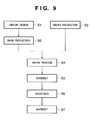
- FIG. 9 is a flow chart of steps in the overall production process for manufacturing semiconductor devices.
- a step S 1 circuit design
- a step S 2 mask production
- producing a mask for the exposure device based on the circuit pattern designed in step S 1 .
- a step S 3 (wafer production) involves producing a wafer using a material such as silicon or the like.
- a step S 4 wafer processing
- a succeeding step S 5 (assembly) is called post-processing, involves using the wafer produced in step S 4 to make a semiconductor chip and includes such assembly processes as assembly (dicing, bonding) and packaging (sealing the chip).
- a step S 6 (inspection) involves testing the operation and reliability of the semiconductor device produced in step S 5 . By such steps is a semiconductor device completed and, in a step S 7 , shipped to customers.
- FIG. 10 is a more detailed flow chart of the above-described wafer processing process using an exposure apparatus according to the present invention.
- a step S 11 the surface of the wafer is oxidized.
- a step S 12 CVD
- an insulating film is laid down over the surface of the wafer.
- a step S 13 electrode formation
- electrodes are vapor-formed on the wafer.
- a step S 14 ion injection
- the wafer is injected with ions.
- a step S 15 resist process
- the wafer is coated with a photosensitizer.
- a step S 16 exposure
- a circuit pattern is etched (exposed) on the surface of the wafer using the semiconductor exposure apparatus described above.
- a step S 17 development
- a step S 18 etching
- everything but the developed resist image is scraped away.
- a step S 19 resist peeling
- the resist which is no longer needed now that etching is completed, is removed.
- the active damping apparatus makes it possible to dampen vibration of the isolation table when driving either the stage and/or the counter-mass separately or independently.
Abstract
Description
- The present invention relates to an improved active damping apparatus, an exposure apparatus and a device manufacturing method, and more particularly, to an active damping apparatus used in an exposure apparatus for imprinting a reticle circuit pattern onto a semiconductor wafer as well as a device manufacturing method employing the exposure apparatus equipped with the active damping apparatus for the manufacture of semiconductor devices.
- Conventionally, in an exposure apparatus used in the manufacture of semiconductor devices, the XY stage is mounted atop a vibration-free device. Generally, these vibration-free devices are of two types: passive vibration-absorbing systems, using air springs, coil springs, vibration-proof rubber or the like to attenuate vibration, and active vibration-damping systems that drive an actuator such as a voice coil motor.
- However, vibration-free devices equipped with the passive vibration-absorbing systems described above, though they may be able to attenuate vibrations transmitted through the floor of the apparatus to some extent, are unable to effectively attenuate vibrations generated by the movement of the XY stage itself.
- Moreover, the passive vibration-absorbing systems described above must strike a good balance between insulation from vibrations propagated through the floor of the apparatus, which is to say vibration-free performance, and the ability to suppress vibration due to movement of the XY stage itself, that is, damping performance.
- In recent years, an active damping system has been suggested, in which, in order to prevent the reaction torque to the driving of the XY stage from forcibly vibrating the isolation table, a counter-mass is driven in a direction opposite the direction in which the stage is driven, so as to offset the drive reaction torque by the movement of the load so that vibrations do not reach the isolation table, the object being to provide a trade-off between vibration-free and vibration damping performance.
- An example of the structure of a conventional active damping device is shown in FIG. 1. The active damping device shown here is designed so that three separate control units, consisting of controllers 31-41 for air spring supports 1, 8, controllers for the stage 18-22, and counter-mass drive controllers 25-29, operate independently. Hereinafter, for convenience, a direction in which a
stage 16 is driven defines the X axis, a direction vertical thereto is the Z axis, a direction through the center of gravity of an isolation table 15 orthogonal to a direction of movement of thestage 16 is the Y axis and an axis of rotation around the y axis is the _Y axis. - The isolation table 15, which mounts the
stage 16 and acounter-mass 23, is supported by air spring supports 1, 8. The air spring supports 1, 8 haveair springs mechanical springs viscosity elements valves air springs position sensors position sensors displacement amplifiers displacement amplifiers displacement analyzer 32. Thedisplacement analyzer 32 then analyzes the readings into a vertical (Z axis) displacement component and a rotational displacement (_Y) component about the Y axis using calculations on a 2×2 matrix having as its elements the displacement and rotation (angle of rotation) of theair springs PI compensators - Next, acceleration readings of the isolation table 15 measured by
acceleration sensors acceleration analyzer 37 after having been fed respectively through each offilters acceleration analyzer 37 then analyzes the acceleration readings into a vertical (Z axis) acceleration component and a rotational (_Y axis) component about the Y axis, using the two inputs from theacceleration sensors thrust allocator 38. - A target
position setting unit 41 then sets a target position for the displacement of the isolation table 15 in the vertical and rotational directions, with a deviation signal between the set target value and thedisplacement analyzer 32 output signal being input to thePI compensators PI compensators acceleration analyzer 37 output signal are then input to thethrust allocator 38. - The
thrust allocator 38 then allocates command values for controlling the air springs in the vertical (Z axis) direction and the rotational (_Y) direction about the Y axis as drive command values for theair springs amplifiers servo valves servo valves air springs position setting unit 41 without steady-state deviation. - The
PI compensators - The foregoing comprises control of the air spring supports 1, 8 for the isolation table 15.
- Position readings from a
position sensor 17 that measures horizontal displacement of thestage 16 mounted atop the isolation table 15 are input to adisplacement amplifier 18. A deviation signal between the output signals from thedisplacement amplifier 18 and the output signals from anintegrator 22 that integrates velocity readings output from atarget velocity generator 21 and generatesstage 16 target position data is then input to aPID compensator 19, so that the extent of adjustment amplified by theamplifier 20 is applied to thestage 16. - Here, the “D” element in the
PID compensator 19 compensates so as to perform differential calculations. Thestage 16 target position command is obtained by integrating the target speed generated by thetarget velocity generator 21 with theintegrator 22, thus completing control of thestage 16. - Further, position readings from a
position sensor 24 that measures horizontal displacement of thecounter-mass 23 mounted on the isolation table 15 are input to adisplacement amplifier 25. A deviation signal between the output signals of adisplacement amplifier 25 and the output signals from anintegrator 29 that integrates velocity readings output by atarget velocity generator 28 and generatescounter-mass 23 target position data is then input to aPID compensator 26, so that an extent of adjustment amplified by anamplifier 27 is applied to thecounter-mass 23, thus completing drive control of thecounter-mass 23. - FIGS. 2A, 2B, 2C, 2D, 2E and 2F are diagrams illustrating stage and counter-mass target values, velocity patterns and acceleration patterns.
- FIGS. 2B and 2E show the time (the X axis) of the target velocity generated by the
target velocity generators stage 16 and thecounter-mass 23. The velocity pattern shown here is known as a trapezoidal velocity pattern, having (from left to right in the diagram) an acceleration region, a constant velocity region and a deceleration region. - FIGS. 2A and 2D show the target acceleration which is a differential of the target velocity with respect to the driving of the
stage 16 and thecontrol counter-mass 23. As can be seen, in regions corresponding to the acceleration and deceleration regions shown in FIGS. 2B and 2E, the direction of acceleration is inverted. In the constant velocity region the acceleration is zero. - FIGS. 2C and 2F show the target position which is an integral of the target velocity with respect to the driving of the
stage 16 and thecounter-mass 23. The position-controlledstage 16 andcounter-mass 23 gradually approach the target positions (indicated by the dotted lines) and are positioned. The extent of the movement to these target positions matches the surface areas of the velocity patterns shown in FIGS. 2B and 2E. - The drive reaction torque arising during acceleration and deceleration of the
stage 16 can be offset by driving thecounter-mass 23 in the opposite direction from thestage 16, so that the drive reaction torque imparted to the isolation table 15 is negated by the moment change due to the load movement. As a result, the drive reaction torque caused by the driving of thestage 16 can be prevented from reaching the isolation table 15. - However, when the
stage 16 andcounter-mass 23 are initialized, that is, when the initial settings are installed or the control parameters updated, etc., thestage 16 and thecounter-mass 23 must be driven independently. But when thestage 16 and thecounter-mass 23 are driven independently, the drive reaction torque and load movement moment so generated are not offset but are transmitted directly to the isolation table 15 as external forces. Moreover, if thestage 16 and thecounter-mass 23 are moved at high speed, the isolation table 15 is agitated by the drive reaction torque and the load movement-generated moment and may exceed permissible drive range limits. - In order to prevent such over-extended movement of the isolation table 15, the
stage 16 and thecounter-mass 23 can be driven at reduced speed so as to achieve the desired initializations. However, when employing an active damping apparatus in a semiconductor exposure apparatus to isolate the stage, the impact of the above-described initializations can result in reduced through-put of the apparatus. - Accordingly, the present invention has been conceived in light of the foregoing considerations, and has as its object to provide an improved active damping apparatus with superior damping performance, and an exposure apparatus employing such improved active damping apparatus.
- The above-described object of the present invention is achieved by an active damping apparatus comprising:
- an isolation table mounting a stage and counter-mass;
- an isolation table controller operatively connected to the isolation table for supporting the isolation table and adjusting a position and attitude of the isolation table;
- a setting unit operatively connected to the controller and adapted to select a combination of the stage and/or the counter-mass to be driven and to set a drive control mode according to what is to be driven; and
- a control input switch operatively connected to the setting unit and adapted to select a control loop that inputs into the isolation table controller a control target value for adjusting the drive of that which is to be driven according to the drive control mode selected by the setting unit,
- the active damping apparatus damping vibration by driving the stage and/or counter-mass mounted on the isolation table so as to offset drive reaction torque and counter-mass movement moment.
- The above-described object of the present invention is also achieved by an exposure apparatus comprising:
- a substrate stage;
- the active damping apparatus described above; and
- a projective optical system for projecting a pattern onto the substrate.
- The above-described object of the present invention is also achieved by a device manufacturing method comprising the steps of:
- coating a substrate with a photosensitive agent;
- exposing the substrate using the exposure apparatus described above; and
- developing the substrate.
- Other objects, features, effects and advantages of the present invention will be apparent from the following description, taken in conjunction with the accompanying drawings, in which like reference characters designate the same or similar parts throughout the figures thereof.
- The accompanying drawings, which are incorporated in and constitute a part of the specification, illustrate embodiments of the invention and, together with the description, serve to explain the principles of the invention, in which:
- FIG. 1 shows an example of the structure of a conventional active damping device;
- FIGS. 2A, 2B, 2C, 2D, 2E and 2F are diagrams illustrating stage and counter-mass target values, velocity patterns and acceleration patterns;
- FIG. 3 is a block diagram illustrating the structure of an active damping apparatus according to a first embodiment of the present invention;
- FIG. 4 is a flow chart illustrating drive control mode settings for the active damping apparatus according to the first embodiment;
- FIGS. 5A, 5B, 5C and 5D are control block diagrams showing schematically the connection structures of the control loop in the case of four different mode settings, specifically, mode settings in which (A) the stage and the counter-mass are driven in tandem, (B) the stage is driven independently, (C) the counter-mass is driven independently, and (D) the stage and the counter-mass are both driven independently of each other;
- FIG. 6 shows filter frequency response characteristics for the first embodiment;
- FIG. 7 shows filter frequency response characteristics for a second embodiment;
- FIG. 8 is a schematic diagram of an exposure apparatus employing the active damping apparatus of the preferred embodiments of the present invention;
- FIG. 9 is a flow chart of steps in the overall production process for manufacturing semiconductor devices; and
- FIG. 10 is a flow chart of the overall wafer processing process.
- Preferred embodiments of the present invention are described in detail in accordance with the accompanying drawings.
- (First Embodiment)
- A description is given of a first embodiment of the present invention, with reference initially to FIGS. 3 and 4.
- FIG. 3 is a block diagram illustrating the structure of an active damping apparatus according to a first embodiment of the present invention, with identical reference numerals denoting elements identical to those shown in the active damping apparatus of FIG. 1.
- FIG. 4 is a flow chart illustrating drive control mode settings for the active damping apparatus according to the first embodiment. That which is to be driven (the stage and the counter-mass, or one of these) is set and the type of control to be conducted by the active damping apparatus is determined. When the
stage 16 atop the isolation table 15 is to be moved (that is, YES at a step S401), the apparatus determines whether or not the counter-mass 23 is to be driven together with the stage 16 (step S402). If the counter-mass 23 is not to be driven with the stage 16 (that is, NO at step S402), the process proceeds to a step S408, setting the control mode to “stage-only drive”.Switch 46 shown in FIG. 3 is turned ON and switch 47 shown in FIG. 3 is turned OFF (step S409).Switches - If it is determined in step S 402 that the counter-mass 23 is also to be driven along with the stage 16 (that is, YES in step S402), and that driving is to offset a drive reaction torque generated by the driving of the stage 16 (a state hereinafter referred to as “in tandem”), that is, YES at step S403, then the process proceeds to a step S404 and the control mode is set to “in tandem”. In this case, both switch 46 and switch 47 of FIG. 3 are turned OFF (step S405). At this time, a control
mode setting unit 300 shown in FIG. 3 activates aswitch 301, turningswitch 301 ON and inputting a control signal (including a target velocity) for driving thestage 16 into thetarget velocity generator 28 for driving thecounter-mass 23. - If in step S 403 it is determined that the driving of the counter-mass 23 is not to be linked with that of the
stage 16 but that each is to be driven independently of the other and by separate commands, then the control mode is set to “independent drive” (step S406). In this case, switch 46 (shown in FIG. 3) is turned ON and switch 47 (also shown in FIG. 3) is also turned ON (step S407). At this time, the controlmode setting unit 300 shown in FIG. 3 turns switch 301 OFF so that a target velocity for thestage 16 is not input into the counter-mass 23 control system. - If in step S 401 it is determined that the stage is not to be driven (that is, NO at step S401) and that the counter-mass 23 alone is to be driven (that is, YES at S410), then the control mode is set to “counter-mass only” (step S411), and switch 46 is turned OFF and switch 47 is turned ON (step S412).
- If in step S 410 it is determined that the counter-mass 23 is not to be driven, (that is, NO at step S410), then the process ends.
- As described above, the active damping apparatus can selectively set to one of four different control modes according to what is to be driven and can switch the configuration of the control loop. What executes the control mode setting are the control
mode setting units switches stage 16 and the counter-mass 23 are not reflected in the disposition of the air springs control system, nor are control signals exchanged between thestage 16 and the counter-mass 23. - When the switches are turned ON, target velocities generated by the
target velocity generators stage 16 and the counter-mass 23 are feed-forwarded into addingpoints filters - The control signals generated by the
target velocity generator 21 are input to thetarget velocity generator 28 that drives the counter-mass 23. - A description is now given of control of the set control mode, with reference initially to FIGS. 5A, 5B, 5C and 5D.
- FIGS. 5A, 5B, 5C and 5D are control block diagrams showing schematically the connection structures of the control loop in the case of four different mode settings, specifically, mode settings in which (A) the stage and the counter-mass are driven in tandem, (B) the stage is driven independently, (C) the counter-mass is driven independently, and (D) the stage and the counter-mass are both driven though independently of each other, respectively.
- (Stage and Counter-Mass in Tandem Mode (S 404))
- The control modes set according to the process depicted in the flow chart described above control the settings of the switches, so that the control loops of the active damping apparatus are reconfigured according to the control mode by these switch settings.
- FIG. 5A is a block diagram showing schematically the connections of the control loop when the in-tandem mode is set in step S 404. In the diagram,
reference numeral 500 indicates schematically the structure of the control loop of thestage 16 and the counter-mass 23, andreference numeral 510 indicates schematically the control loop of the air springs 3 (10). The controlmode setting unit 300 shown in FIG. 3 controls switch 301 and the target velocity generated by thetarget velocity generator 21 is input to thetarget velocity generator 28 for the counter-mass. - The input of such target velocity causes a target value for accomplishing a movement that generates a force that offsets the drive reaction torque generated by the driving of the
stage 16 to be generated by thetarget velocity generator 28 and input to the counter-mass 23. - The offsetting of the drive reaction torque, for example in a case in which a thrust F at the
stage 16 is transmitted to the isolation table 15, involves an offset force -F generated by the driving of the counter-mass 23, such that the sum total of the two forces is zero. This relation holds not just for translational direction force but also for rotational direction moment, with the counter-mass control loop operating so that the moment sum total is zero. So when the drive reaction torque is fully offset by the linked motion of the stage and the counter-mass, the stage can be settled at its target position unaffected by any residual vibration. - In the in-tandem control mode, switches 46 and 47 are OFF, so in the control loop for adjusting the air springs there are no control commands input from the stage and the counter-mass. As a result, the air spring target
position setting unit 41 controls the positioning of the air springs 3 (10) by executing independent control loops for the stage and the counter-mass. - (Stage Alone Driven, Independently (S 408))
- FIG. 5B is a block diagram showing schematically the connections of the control loop when only the stage is set to be driven, in step S 408. (For simplicity, the
displacement amplifier 18,PID compensator 19 andintegrator 22 have been omitted from the drawing.) The controlmode setting unit 300 shown in FIG. 3 turns switch 301 OFF, dividing the control loop so thatstage 16 target values are not input to the counter-mass 23 side. The target value generated by the stagetarget velocity generator 21 is input to thestage 16 and that drive data is detected by theposition sensor 17 and fed back to the control loop. - The control
mode setting unit 44 of FIG. 3 turns switch 46 ON, inputting the target value generated by the stagetarget velocity generator 21 to the air springs. The air springs 3 (10) control system is formed by a control loop consisting mainly of air spring targetposition setting unit 41 and sensor 4 (11) and thrustdistributor 38. (For simplicity,displacement amplifiers PI compensators amplifiers filter 42 have been omitted from the drawing.) - At this time, the target value generated by the
target velocity generator 21 is input both to the integrator 22 (shown in FIG. 3) that forms the control loop for the stage as well as to the filter 41 (shown in FIG. 3). The stage target velocity data passed through thefilter 42 is input to the controlmode setting unit 44 and, viaswitch 46, to the control unit for the air spring supports 1, 8 (506). - FIG. 6 shows frequency response characteristics of the filter for the first embodiment. The filter shown is a low-pass filter with a cut-off frequency of fH. A high-frequency component of a generated target velocity is cut off by passing through the filter, and thus rapid changes in input can be prevented from reaching the isolation table 15 air springs even when the
stage 16 andcounter-mass 23 target velocity changes discontinuously. In the present embodiment, thefilter 42 for the stage target velocity and thefilter 43 for the counter-mass target velocity are given the same cut-off frequency. However, it is possible to have different cut-off frequencies for the two filters and still achieve the object of the present invention. - In a state of equilibrium, the transfer function for the air springs where the servo valve input current is I and the air spring pressure is P can be approximated by the integral characteristics given in the following formula:

- where Gq is the servo valve flow gain, k is the ratio of specific heat, P0 is the spring pressure in a state of equilibrium, V0 is the air spring capacity in a state of equilibrium and s is the Laplace operator.
- Therefore, the target velocity of the stage that is feed-forwarded into the control system for rotational displacement about the Y axis of the isolation table 15 (_Y axis) is integrated using the integral characteristic of the air springs of formula (1), with the feed forward of the target velocity is equivalent to applying a rotational moment to the isolation table 15 that is proportional to the position of the
stage 16. - The feed-forward of the target velocity allows the
thrust distributor 38 to generate at the air springs 3, 10 a support moment for offsetting the rotational moment generated by the movement of thestage 16. The position of air springs is detected by theposition sensors point 505 via thedisplacement amplifiers displacement analyzer 32 and thePI compensators - In other words, even when the
stage 16 alone is driven independently, data concerning the drive control for thestage 16 is input to the air springs control loop and the output of the air springs can be adjusted according to the stage drive data. Accordingly, when thestage 16 alone is driven, vibration of the isolation table can be dampened by coordination with the air springs control. - (Counter-Mass Alone Driven, Independently (S 411))
- FIG. 5C is a control block diagram showing schematic connections of the control loop when the counter-mass alone is set to be driven (step S 411). (For simplicity, the
displacement amplifier 25,PID compensator 26,integrator 29, etc., have been omitted from FIG. 5C.) The controlmode setting unit 300 of FIG. 3 turns switch 301 OFF. Therefore, the counter-mass 23 is driven according to the target value generated by thetarget velocity generator 28, that position is detected by theposition sensor 24 and fed back to the control loop. - The control mode setting unit 45 (shown in FIG. 3) turns
switch 47 ON, inputting the target value generated by thetarget velocity generator 28 to the air springs control system. The air springs 3 (10) control system is substantially identical to that shown in FIG. 5B, and forms a control loop composed of targetposition setting unit 41, position sensors 4 (11) and thrustdistributor 38. (For simplicity, thedisplacement amplifiers PI compensators amplifiers filter 43 have been omitted from FIG. 5C.) - At this time, the target velocity generated by the
target velocity generator 28 is input both to the integrator 29 (shown in FIG. 3) that forms the control loop for the counter-mass 23 as well as to the filter 43 (shown in FIG. 3). As described above, thisfilter 43 has the particular frequency response shown in FIG. 6, such thatcounter-mass 23 target velocity that has been filtered by thisfilter 43 is input to the air springs control loop via the controlmode setting unit 45 and theswitch 47. - The
filter 43, as shown in FIG. 6, is a low-pass filter with a cut-off frequency of fH. The cut-off frequency may be set to be either different from or the same as that offilter 42. - The air springs transfer function, as described above with respect to formula (1), has an integral characteristic, so the counter-mass 23 target velocity that is feed-forwarded into the control system for the rotational displacement about the Y axis of the isolation table 15 (that is, the _Y axis) is integrated by the integral characteristic of the air springs according to formula (1), with the feed forward of the target velocity is equivalent to applying a rotational moment to the isolation table 15 that is proportional to the position of the
stage 16. - The feed-forward of the target velocity allows the
thrust distributor 38 to generate at the air springs 3, 10 a support moment for offsetting the rotational moment generated by the movement of the counter-mass 23. The position of air springs is detected by theposition sensors point 505 via thedisplacement amplifiers displacement analyzer 32 and thePI compensators - Accordingly, when the counter-mass 23 alone is driven, vibration of the isolation table can be dampened by coordination with the air springs controller.
- (Mode in Which Both the Stage and the Counter-Mass are Driven Independently of Each Other (Step S 406))
- FIG. 5D is a block diagram indicating schematic connections in a control loop when a mode is set in which both the stage and the counter-mass are to be driven, though independently of each other. In such case, the control
mode setting unit 300 of FIG. 3 turns switch 301 OFF, dividing the control loop so that no stage target velocity is input to the counter-mass 23 side. - The control mode setting unit 44 (shown in FIG. 3) turns
switch 46 ON, inputting the target value generated by thetarget velocity generator 21 to the air springs control system. The air springs 3 control system consists substantially of the control loop formed by the targetposition setting unit 41 for the air springs, position sensors 4 (11) and thrustdistributor 38. (As with FIGS. 5B and 5C, for simplicity thedisplacement amplifiers PI compensators amplifiers filter 42 have been omitted from FIG. 5C.) - In addition, the control mode setting unit 45 (shown in FIG. 3) turns
switch 47 ON, inputting the target value generated by thetarget velocity generator 28 to the air springs control system. -
Stage 16 target velocity is input to the controller for the air springs control system via the controlmode setting unit 44 and the switch 46 (506). In addition, the counter-mass 23 target velocity is input to the controller for the air springs control system via the controlmode setting unit 25 and the switch 47 (507). - The feed-forward input of the target velocity enables the air springs control system to absorb the impact of the rotational moment generated by the movement of the
stage 16 and the counter-mass 23. - Accordingly, vibration of the isolation table when the
stage 16 or the counter-mass 23 alone is driven can be dampened by coordination with the air springs controller. - As described above, by switching input to the isolation table controller of the control target values for the stage and the counter-mass according to that which is to be driven, the active damping apparatus according to the first embodiment of the present invention, makes it possible to dampen vibration of the isolation table 15 when driving either the stage and/or the counter-mass separately or independently.
- (Second Embodiment)
- A description is now given of an active damping apparatus according to a second embodiment of the present invention, with reference in the first instance to FIG. 7.
- FIG. 7 shows filter frequency response characteristics for a second embodiment.
- In the first embodiment described above, the air springs control system is given as the transfer function having the integral characteristic described by formula (1). However, an active damping apparatus having the structure depicted in FIG. 3 can also be adapted to a control system that approximates servo valve characteristics using a time lag of first order system. If the
filters - By using a filter having a frequency response like that shown in FIG. 7, even in a case in which, for example, the characteristics are such that the transfer function of the
servo valves stage 16 alone, the counter-mass 23 alone, or thestage 16 andcounter-mass 23 independently. - Further, it should be noted that although the first and second embodiments described above have two vertical air spring supports that support the isolation table 15, the present invention is not limited to such an arrangement but may use three or more such supports. In such a case, the isolation table position control system is composed of three separate control systems, for translational movement along the Z axis, rotational movement about the X axis and rotational movement about the Y axis. In such case, 3×3 matrix computations are conducted at the displacement analyzer, the velocity analyzer and the thrust distributor, thus adapting position adjustment control to the setting mode.
- The air springs that support the isolation table need not necessarily be disposed vertically but may additionally be mounted so as to drive the isolation table 15 horizontally. By mounting the air springs horizontally, horizontal vibration of the isolation table can be suppressed.
- Also, an electromagnetic actuator may further be mounted in order to drive the isolation table 15 in the horizontal direction. By mounting an electromagnetic actuator that drives horizontally (along the X axis), the drive reaction torque that is generated when the
stage 16 and the counter-mass 23 are driven independently is absorbed by the driving of the electromagnetic actuator, and it is also possible to coordinate the driving of the electromagnetic actuator with the air springs control system so as to offset vibration. - In addition, the movement of the stage and counter-mass may be either within a two-dimensional flat plane like the XY stage or, when three air spring supports are provided in directions that include the vertical (that is, providing in FIG. 3 an additional air spring support in the Y-axis direction), by feed-forward of the target velocity of the XY stage and the counter-mass along the X axis to the control loop that controls _Y axis rotation of the air springs control system and by feed-forward of the target velocity of the XY stage and the counter-mass along the Y axis to the control loop that controls _X axis rotational displacement of the air springs about the X axis. By so doing, vibration of the isolation table 15 can be dampened as described above with respect to control modes even when the XY stage and the counter-mass are set to move independently.
- (Third Embodiment)
- A description is now given of a third embodiment of the present invention, with reference initially to FIG. 8.
- FIG. 8 is a schematic diagram of an exposure apparatus employing the active damping apparatus of the preferred embodiments of the present invention.
- In the exposure apparatus shown in FIG. 8, a
reticle mask 221 supported by areticle mask stage 220 is illuminated by an illumination optical system and thereticle mask 221 pattern is projected by a projectiveoptical system 230 onto a substrate 241 (that is, a wafer) atop a substrate (wafer)stage 240, exposing thewafer 241. Here, thewafer stage 240 employs the active damping apparatus shown in FIG. 3. - By using the active damping apparatus according to the present invention in the exposure apparatus, it is possible to reduce vibration attendant upon movement of the stage, to improve the overlay and line width precision and to increase through-put.
- Additionally, it becomes possible to initialize the settings of the stage efficiently so as to improve the through-put of the exposure apparatus.
- A description is now given of a device manufacturing method employing the above-described exposure apparatus equipped with the active damping apparatus according to the present invention for the manufacture of semiconductor devices.
- FIG. 9 is a flow chart of steps in the overall production process for manufacturing semiconductor devices.
- As shown in the diagram, a step S 1 (circuit design) involves designing the circuit of the semiconductor device. A step S2 (mask production) involves producing a mask for the exposure device based on the circuit pattern designed in step S1.
- Meanwhile, a step S 3 (wafer production) involves producing a wafer using a material such as silicon or the like. A step S4 (wafer processing) is called pre-processing, and involves using the mask and housing prepared as described above and forming an actual circuit in the wafer by lithography. A succeeding step S5 (assembly) is called post-processing, involves using the wafer produced in step S4 to make a semiconductor chip and includes such assembly processes as assembly (dicing, bonding) and packaging (sealing the chip). A step S6 (inspection) involves testing the operation and reliability of the semiconductor device produced in step S5. By such steps is a semiconductor device completed and, in a step S7, shipped to customers.
- FIG. 10 is a more detailed flow chart of the above-described wafer processing process using an exposure apparatus according to the present invention.
- As shown in the diagram, in a step S 11 (oxidation), the surface of the wafer is oxidized. In a step S12 (CVD), an insulating film is laid down over the surface of the wafer. In a step S13 (electrode formation), electrodes are vapor-formed on the wafer. In a step S14 (ion injection), the wafer is injected with ions. In a step S15 (resist process), the wafer is coated with a photosensitizer. In a step S16 (exposure), a circuit pattern is etched (exposed) on the surface of the wafer using the semiconductor exposure apparatus described above. In a step S17 (development), the exposed wafer is developed. In a step S18 (etching), everything but the developed resist image is scraped away. In a step S19 (resist peeling), the resist, which is no longer needed now that etching is completed, is removed. By repeating these steps, a multi-layered circuit pattern is formed on the wafer.
- As described above, by switching input to the isolation table controller of the control target values for the stage and the counter-mass according to that which is to be driven, the active damping apparatus according to the present invention makes it possible to dampen vibration of the isolation table when driving either the stage and/or the counter-mass separately or independently.
- The present invention is not limited to the above-described embodiments, and various changes and modifications can be made within the spirit and scope of the present invention. Therefore, in order to apprise the public of the scope of the present invention, the following claims are made.
Claims (12)
Priority Applications (1)
| Application Number | Priority Date | Filing Date | Title |
|---|---|---|---|
| US11/130,240 US7264235B2 (en) | 2002-04-19 | 2005-05-17 | Active damping apparatus, exposure apparatus and device manufacturing method |
Applications Claiming Priority (2)
| Application Number | Priority Date | Filing Date | Title |
|---|---|---|---|
| JP2002-118003 | 2002-04-19 | ||
| JP2002118003A JP4109891B2 (en) | 2002-04-19 | 2002-04-19 | Active vibration control apparatus, exposure apparatus, and device manufacturing method |
Related Child Applications (1)
| Application Number | Title | Priority Date | Filing Date |
|---|---|---|---|
| US11/130,240 Division US7264235B2 (en) | 2002-04-19 | 2005-05-17 | Active damping apparatus, exposure apparatus and device manufacturing method |
Publications (2)
| Publication Number | Publication Date |
|---|---|
| US20030197845A1 true US20030197845A1 (en) | 2003-10-23 |
| US6937317B2 US6937317B2 (en) | 2005-08-30 |
Family
ID=29207846
Family Applications (2)
| Application Number | Title | Priority Date | Filing Date |
|---|---|---|---|
| US10/412,315 Expired - Fee Related US6937317B2 (en) | 2002-04-19 | 2003-04-14 | Active damping apparatus, exposure apparatus and device manufacturing method |
| US11/130,240 Expired - Fee Related US7264235B2 (en) | 2002-04-19 | 2005-05-17 | Active damping apparatus, exposure apparatus and device manufacturing method |
Family Applications After (1)
| Application Number | Title | Priority Date | Filing Date |
|---|---|---|---|
| US11/130,240 Expired - Fee Related US7264235B2 (en) | 2002-04-19 | 2005-05-17 | Active damping apparatus, exposure apparatus and device manufacturing method |
Country Status (2)
| Country | Link |
|---|---|
| US (2) | US6937317B2 (en) |
| JP (1) | JP4109891B2 (en) |
Cited By (11)
| Publication number | Priority date | Publication date | Assignee | Title |
|---|---|---|---|---|
| EP1619407A1 (en) * | 2004-07-20 | 2006-01-25 | Canon Kabushiki Kaisha | Exposure apparatus and semiconductor device manufacturing method |
| US20060028630A1 (en) * | 2004-08-05 | 2006-02-09 | Canon Kabushiki Kaisha | Liquid immersion exposure apparatus, method of controlling the same, and device manufacturing method |
| US20060033903A1 (en) * | 2004-08-13 | 2006-02-16 | Nikon Corporation | Moving mechanism with high bandwidth response and low force transmissibility |
| US20060036352A1 (en) * | 2003-11-17 | 2006-02-16 | Canon Kabushiki Kaisha | Anti-vibration technique |
| US20070097340A1 (en) * | 2005-10-31 | 2007-05-03 | Nikon Corporation | Active damper with counter mass to compensate for structural vibrations of a lithographic system |
| US20080114473A1 (en) * | 2006-11-08 | 2008-05-15 | Integrated Dynamics Engineering Gmbh | Combined motion control system |
| US20080308749A1 (en) * | 2007-06-14 | 2008-12-18 | Asml Netherlands B.V. | Lithographic apparatus and device manufacturing method |
| US20120069316A1 (en) * | 2010-09-08 | 2012-03-22 | Nikon Corporation | Methods for limiting counter-mass trim-motor force and stage assemblies incorporating same |
| US20130249445A1 (en) * | 2010-11-26 | 2013-09-26 | Canon Kabushiki Kaisha | Control apparatus of vibration-type actuator |
| US8619361B2 (en) * | 2010-03-31 | 2013-12-31 | Nikon Corporation | Direct derivative feedforward vibration compensation system |
| EP3570419A4 (en) * | 2017-01-11 | 2020-01-22 | Mitsubishi Electric Corporation | Recoilless device and directivity control mirror system |
Families Citing this family (17)
| Publication number | Priority date | Publication date | Assignee | Title |
|---|---|---|---|---|
| EP1664587B1 (en) * | 2003-09-05 | 2010-11-24 | Koninklijke Philips Electronics N.V. | Actuator arrangement for active vibration isolation comprising an inertial reference mass |
| JP4655039B2 (en) * | 2004-06-07 | 2011-03-23 | 株式会社ニコン | Stage apparatus, exposure apparatus, and exposure method |
| US7557529B2 (en) * | 2005-01-11 | 2009-07-07 | Nikon Corporation | Stage unit and exposure apparatus |
| JP4747336B2 (en) * | 2005-03-31 | 2011-08-17 | 学校法人慶應義塾 | Variable structure semi-active seismic isolation system |
| US7484357B2 (en) * | 2005-09-15 | 2009-02-03 | Cummins, Inc | Apparatus, system, and method for determining and implementing estimate reliability |
| JP2007188251A (en) * | 2006-01-12 | 2007-07-26 | Sumitomo Heavy Ind Ltd | Stage apparatus |
| US7649613B2 (en) * | 2006-03-03 | 2010-01-19 | Asml Netherlands B.V. | Lithographic apparatus, method of controlling a component of a lithographic apparatus and device manufacturing method |
| WO2008066035A1 (en) | 2006-11-30 | 2008-06-05 | Mitsubishi Electric Corporation | Seismic isolation control system |
| CN101177199B (en) * | 2007-12-04 | 2012-11-28 | 南京大学 | Resonance type high-speed high-precision multi-station turning table |
| NL2003772A (en) * | 2008-12-11 | 2010-06-14 | Asml Netherlands Bv | Lithographic apparatus and a method to compensate for the effect of disturbances on the projection system of a lithographic apparatus. |
| US20110031668A1 (en) * | 2009-08-10 | 2011-02-10 | Raytheon Company | Vibration Isolation System |
| JP6727018B2 (en) * | 2016-04-22 | 2020-07-22 | 三菱電機株式会社 | Mechanical device and vibration control method for mechanical device |
| JP6731776B2 (en) * | 2016-04-22 | 2020-07-29 | 三菱電機株式会社 | Mechanical device and method of manufacturing mechanical device |
| KR20180029145A (en) | 2016-09-09 | 2018-03-20 | 삼성전자주식회사 | substrate processing apparatus |
| JP6806509B2 (en) * | 2016-09-15 | 2021-01-06 | キヤノン株式会社 | Method of manufacturing exposure equipment and articles |
| JP6556196B2 (en) * | 2017-07-27 | 2019-08-07 | 倉敷化工株式会社 | Active vibration isolator |
| KR101977308B1 (en) * | 2017-08-28 | 2019-05-13 | (주)대일시스템 | Active vibration control apparatus and disturbance control method of conveyer using the same |
Citations (3)
| Publication number | Priority date | Publication date | Assignee | Title |
|---|---|---|---|---|
| US140921A (en) * | 1873-07-15 | Improvement in machines for making stereotype-molds | ||
| US5936710A (en) * | 1996-01-05 | 1999-08-10 | Canon Kabushiki Kaisha | Scanning type exposure apparatus, position control apparatus, and method therefor |
| US6408045B1 (en) * | 1997-11-11 | 2002-06-18 | Canon Kabushiki Kaisha | Stage system and exposure apparatus with the same |
Family Cites Families (18)
| Publication number | Priority date | Publication date | Assignee | Title |
|---|---|---|---|---|
| JP2808677B2 (en) | 1989-06-20 | 1998-10-08 | 株式会社ニコン | Stage drive method |
| JPH03125048A (en) | 1989-10-11 | 1991-05-28 | Nikon Corp | Vibration absorbing type stage device |
| US5127622A (en) * | 1991-06-27 | 1992-07-07 | Allied-Signal Inc. | Fluidic vibration cancellation mount and method |
| US5251863A (en) * | 1992-08-12 | 1993-10-12 | Noise Cancellation Technologies, Inc. | Active force cancellation system |
| JP2816513B2 (en) * | 1992-08-26 | 1998-10-27 | 鹿島建設株式会社 | Electromagnetic floating floor structure |
| JPH10112433A (en) | 1996-10-04 | 1998-04-28 | Nikon Corp | Seismic base isolation device and exposure device |
| JP4313865B2 (en) | 1998-01-14 | 2009-08-12 | キヤノン株式会社 | Vibration isolator |
| US6123312A (en) * | 1998-11-16 | 2000-09-26 | Dai; Yuzhong | Proactive shock absorption and vibration isolation |
| JP2000228343A (en) | 1999-02-04 | 2000-08-15 | Canon Inc | Active vibration-isolating device, projection aligner, and device-manufacturing method |
| JP3726207B2 (en) | 1999-07-14 | 2005-12-14 | 株式会社日立製作所 | Active vibration isolator |
| JP2001077009A (en) | 1999-09-07 | 2001-03-23 | Nikon Corp | Substrate processing system |
| JP2001264015A (en) | 2000-03-21 | 2001-09-26 | Nikon Corp | Position-detecting method, position detector, and aligner |
| US6718294B1 (en) * | 2000-05-16 | 2004-04-06 | Mindspeed Technologies, Inc. | System and method for synchronized control of system simulators with multiple processor cores |
| JP2002242983A (en) | 2001-02-19 | 2002-08-28 | Canon Inc | Active vibration resistant system |
| JP2002286083A (en) * | 2001-03-27 | 2002-10-03 | Canon Inc | Vibration prevention device, device production apparatus and method, and maintenance for semiconductor factory and device production apparatus |
| US7100033B2 (en) * | 2002-10-23 | 2006-08-29 | Intel Corporation | Controlling the timing of test modes in a multiple processor system |
| US7536597B2 (en) * | 2005-04-27 | 2009-05-19 | Texas Instruments Incorporated | Apparatus and method for controlling power, clock, and reset during test and debug procedures for a plurality of processor/cores |
| US7409330B2 (en) * | 2005-06-16 | 2008-08-05 | Kabushiki Kaisha Toshiba | Method and system for software debugging using a simulator |
-
2002
- 2002-04-19 JP JP2002118003A patent/JP4109891B2/en not_active Expired - Fee Related
-
2003
- 2003-04-14 US US10/412,315 patent/US6937317B2/en not_active Expired - Fee Related
-
2005
- 2005-05-17 US US11/130,240 patent/US7264235B2/en not_active Expired - Fee Related
Patent Citations (4)
| Publication number | Priority date | Publication date | Assignee | Title |
|---|---|---|---|---|
| US140921A (en) * | 1873-07-15 | Improvement in machines for making stereotype-molds | ||
| US5936710A (en) * | 1996-01-05 | 1999-08-10 | Canon Kabushiki Kaisha | Scanning type exposure apparatus, position control apparatus, and method therefor |
| US6160612A (en) * | 1996-01-05 | 2000-12-12 | Canon Kabushiki Kaisha | Scanning type exposure apparatus, position control apparatus, and method therefor |
| US6408045B1 (en) * | 1997-11-11 | 2002-06-18 | Canon Kabushiki Kaisha | Stage system and exposure apparatus with the same |
Cited By (20)
| Publication number | Priority date | Publication date | Assignee | Title |
|---|---|---|---|---|
| US20060036352A1 (en) * | 2003-11-17 | 2006-02-16 | Canon Kabushiki Kaisha | Anti-vibration technique |
| US7024284B2 (en) | 2003-11-17 | 2006-04-04 | Canon Kabushiki Kaisha | Anti-vibration technique |
| US7069114B2 (en) | 2003-11-17 | 2006-06-27 | Canon Kabushiki Kaisha | Anti-vibration technique |
| US20060206237A1 (en) * | 2003-11-17 | 2006-09-14 | Canon Kabushiki Kaisha | Anti-vibration technique |
| US20060017908A1 (en) * | 2004-07-20 | 2006-01-26 | Canon Kabushiki Kaisha | Exposure apparatus and semiconductor device manufacturing method |
| EP1619407A1 (en) * | 2004-07-20 | 2006-01-25 | Canon Kabushiki Kaisha | Exposure apparatus and semiconductor device manufacturing method |
| US7692760B2 (en) | 2004-08-05 | 2010-04-06 | Canon Kabushiki Kaisha | Liquid immersion exposure apparatus, method of controlling the same, and device manufacturing method |
| US20060028630A1 (en) * | 2004-08-05 | 2006-02-09 | Canon Kabushiki Kaisha | Liquid immersion exposure apparatus, method of controlling the same, and device manufacturing method |
| US20060033903A1 (en) * | 2004-08-13 | 2006-02-16 | Nikon Corporation | Moving mechanism with high bandwidth response and low force transmissibility |
| US7333179B2 (en) * | 2004-08-13 | 2008-02-19 | Nikon Corporation | Moving mechanism with high bandwidth response and low force transmissibility |
| US20070097340A1 (en) * | 2005-10-31 | 2007-05-03 | Nikon Corporation | Active damper with counter mass to compensate for structural vibrations of a lithographic system |
| US20080114473A1 (en) * | 2006-11-08 | 2008-05-15 | Integrated Dynamics Engineering Gmbh | Combined motion control system |
| US8751050B2 (en) * | 2006-11-08 | 2014-06-10 | Integrated Dynamics Engineering Gmbh | Combined motion control system |
| US20080308749A1 (en) * | 2007-06-14 | 2008-12-18 | Asml Netherlands B.V. | Lithographic apparatus and device manufacturing method |
| US8044373B2 (en) * | 2007-06-14 | 2011-10-25 | Asml Netherlands B.V. | Lithographic apparatus and device manufacturing method |
| US8619361B2 (en) * | 2010-03-31 | 2013-12-31 | Nikon Corporation | Direct derivative feedforward vibration compensation system |
| US20120069316A1 (en) * | 2010-09-08 | 2012-03-22 | Nikon Corporation | Methods for limiting counter-mass trim-motor force and stage assemblies incorporating same |
| US9529353B2 (en) * | 2010-09-08 | 2016-12-27 | Nikon Corporation | Methods for limiting counter-mass trim-motor force and stage assemblies incorporating same |
| US20130249445A1 (en) * | 2010-11-26 | 2013-09-26 | Canon Kabushiki Kaisha | Control apparatus of vibration-type actuator |
| EP3570419A4 (en) * | 2017-01-11 | 2020-01-22 | Mitsubishi Electric Corporation | Recoilless device and directivity control mirror system |
Also Published As
| Publication number | Publication date |
|---|---|
| JP2003314610A (en) | 2003-11-06 |
| US20050217956A1 (en) | 2005-10-06 |
| US6937317B2 (en) | 2005-08-30 |
| US7264235B2 (en) | 2007-09-04 |
| JP4109891B2 (en) | 2008-07-02 |
Similar Documents
| Publication | Publication Date | Title |
|---|---|---|
| US7264235B2 (en) | Active damping apparatus, exposure apparatus and device manufacturing method | |
| US6408045B1 (en) | Stage system and exposure apparatus with the same | |
| EP1124078B1 (en) | Active anti-vibration apparatus and exposure apparatus | |
| US9304404B2 (en) | Arrangement for actuating an element in a microlithographic projection exposure apparatus | |
| US20070097340A1 (en) | Active damper with counter mass to compensate for structural vibrations of a lithographic system | |
| JPH11315883A (en) | Vibration damping device, exposing device and manufacture of device | |
| US7768626B2 (en) | Exposure apparatus | |
| JP2000274482A (en) | Active vibration resistant device, exposure device and method, and manufacture of device | |
| US6864962B2 (en) | Active anti-vibration apparatus and exposure apparatus and device manufacturing method using the same | |
| US7133115B2 (en) | Positioning device, exposure apparatus using the positioning device, and device production method | |
| JP4109747B2 (en) | Active vibration isolator and exposure apparatus | |
| JP6566192B2 (en) | Anti-vibration apparatus, exposure apparatus, and device manufacturing method | |
| JP4165844B2 (en) | Vibration isolator | |
| JP2007184621A (en) | Device for controlling vibration and method of controlling vibration, exposure device and method of fabricating device | |
| US20050140961A1 (en) | Anti-vibration system, method of controlling the same, exposure apparatus, and device manufacturing method | |
| JP2001140972A (en) | Vibration resistant device | |
| JP2003280744A (en) | Vibration control device and method, exposure device having the same device and manufacturing method of semiconductor device | |
| JP2000012435A (en) | Oscillation removing device and aligner | |
| JP2002367893A (en) | Aligner | |
| JP2004111653A (en) | Positioning device, exposure device applying the locating device thereto and manufacturing method of semiconductor device | |
| JP2003324056A (en) | Vibration suppression device, control method therefor, aligner and method of manufacturing semiconductor device | |
| JP2000068195A (en) | Device manufacturing equipment | |
| JP2000136845A (en) | Active vibration insulating device and exposure device using it | |
| JP2001221279A (en) | Active vibration damping device | |
| JP2000220690A (en) | Active vibration-absorbing device, exposure device and manufacture of device |
Legal Events
| Date | Code | Title | Description |
|---|---|---|---|
| AS | Assignment |
Owner name: CANON KABUSHIKI KAISHA, JAPAN Free format text: ASSIGNMENT OF ASSIGNORS INTEREST;ASSIGNOR:MORISADA, MASAHIRO;REEL/FRAME:013978/0992 Effective date: 20030407 |
|
| FPAY | Fee payment |
Year of fee payment: 4 |
|
| FPAY | Fee payment |
Year of fee payment: 8 |
|
| REMI | Maintenance fee reminder mailed | ||
| LAPS | Lapse for failure to pay maintenance fees |
Free format text: PATENT EXPIRED FOR FAILURE TO PAY MAINTENANCE FEES (ORIGINAL EVENT CODE: EXP.) |
|
| STCH | Information on status: patent discontinuation |
Free format text: PATENT EXPIRED DUE TO NONPAYMENT OF MAINTENANCE FEES UNDER 37 CFR 1.362 |
|
| FP | Lapsed due to failure to pay maintenance fee |
Effective date: 20170830 |