US20050228551A1 - Fog tester apparatus - Google Patents
Fog tester apparatus Download PDFInfo
- Publication number
- US20050228551A1 US20050228551A1 US10/921,357 US92135704A US2005228551A1 US 20050228551 A1 US20050228551 A1 US 20050228551A1 US 92135704 A US92135704 A US 92135704A US 2005228551 A1 US2005228551 A1 US 2005228551A1
- Authority
- US
- United States
- Prior art keywords
- light source
- fog
- aircraft
- light
- collimator
- Prior art date
- Legal status (The legal status is an assumption and is not a legal conclusion. Google has not performed a legal analysis and makes no representation as to the accuracy of the status listed.)
- Granted
Links
Images


Classifications
-
- G—PHYSICS
- G09—EDUCATION; CRYPTOGRAPHY; DISPLAY; ADVERTISING; SEALS
- G09B—EDUCATIONAL OR DEMONSTRATION APPLIANCES; APPLIANCES FOR TEACHING, OR COMMUNICATING WITH, THE BLIND, DEAF OR MUTE; MODELS; PLANETARIA; GLOBES; MAPS; DIAGRAMS
- G09B9/00—Simulators for teaching or training purposes
- G09B9/02—Simulators for teaching or training purposes for teaching control of vehicles or other craft
- G09B9/08—Simulators for teaching or training purposes for teaching control of vehicles or other craft for teaching control of aircraft, e.g. Link trainer
- G09B9/30—Simulation of view from aircraft
- G09B9/36—Simulation of night or reduced visibility flight
-
- G—PHYSICS
- G09—EDUCATION; CRYPTOGRAPHY; DISPLAY; ADVERTISING; SEALS
- G09B—EDUCATIONAL OR DEMONSTRATION APPLIANCES; APPLIANCES FOR TEACHING, OR COMMUNICATING WITH, THE BLIND, DEAF OR MUTE; MODELS; PLANETARIA; GLOBES; MAPS; DIAGRAMS
- G09B9/00—Simulators for teaching or training purposes
- G09B9/02—Simulators for teaching or training purposes for teaching control of vehicles or other craft
- G09B9/08—Simulators for teaching or training purposes for teaching control of vehicles or other craft for teaching control of aircraft, e.g. Link trainer
- G09B9/16—Ambient or aircraft conditions simulated or indicated by instrument or alarm
- G09B9/165—Condition of cabin, cockpit or pilot's accessories
-
- G—PHYSICS
- G09—EDUCATION; CRYPTOGRAPHY; DISPLAY; ADVERTISING; SEALS
- G09B—EDUCATIONAL OR DEMONSTRATION APPLIANCES; APPLIANCES FOR TEACHING, OR COMMUNICATING WITH, THE BLIND, DEAF OR MUTE; MODELS; PLANETARIA; GLOBES; MAPS; DIAGRAMS
- G09B9/00—Simulators for teaching or training purposes
- G09B9/02—Simulators for teaching or training purposes for teaching control of vehicles or other craft
- G09B9/08—Simulators for teaching or training purposes for teaching control of vehicles or other craft for teaching control of aircraft, e.g. Link trainer
- G09B9/30—Simulation of view from aircraft
- G09B9/36—Simulation of night or reduced visibility flight
- G09B9/38—Simulation of runway outlining or approach lights
Definitions
- This invention relates to testing equipment and methods, in particular, an apparatus that can be used to test the fog-penetrating capability of infrared visibility improvement systems for aircraft.
- the apparatus can be used for either a lab/production facility or for the flight line when it is installed in the aircraft.
- EVS Kollsman Enhanced Vision System
- this system consists of a Forward Looking IR (FLIR) Sensor, an electronics processing box and an infrared window installed in the aircraft radome.
- Video processing software algorithms display an infrared image of the approaching lights, runways, taxiways, as well as other structures such as buildings, ground vehicles, lighted and unlighted aircraft, terrain, etc. The image is displayed to the pilot via any raster capable Head-Up Display (HUD) or a head-down display such as a Cathode Ray Tube (CRT).
- HUD Head-Up Display
- CRT Cathode Ray Tube
- Another aspect of the invention is to provide an apparatus that can be calibrated such that a properly operating EVS is able to detect and display the simulated pattern on the HUD or head-down display.
- Still another aspect of the invention is to provide a fog tester apparatus which contains a light source which emulates runway landing lights.
- FIG. 1 is an illustration of the fog tester apparatus in accordance with the invention for the lab testing embodiment.
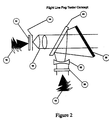
- FIG. 2 is an illustration of the illustration of the flight line fog tester embodiment.
- FIG. 1 the major components of invention are illustrated. All components are commercially available and were modified to meet specific Field of View and bandpass (frequency) requirements of the EVS.
- the fog filter attenuation was derived from data obtained from NASA.
- the MALS light source is a standard commercial item from General Electric Corporation.
- the infrared transmissions are in the spectral filter bands of 1.3 to 2.5 microns.
- Neutral density filter wheel 1 has five distinct filters. Each filter represents the intensity of the landing lights, which represents the increasing distances beyond the minimum detection area of the Runway Visible Range (RVR).
- RVR Runway Visible Range
- the infrared transmissions are in spectral filter bands of 1.3 to 2.5 microns. Wheel 1 is able to be heated by an external source to 10° C. above the ambient temperature.
- the spectral filter transmission is preferably about 39.76%, ⁇ 0.0%, +5.0%.
- the filters are used to simulate fog transmission from a minimum specified range to +4 second in flight range.
- Fog filter 2 preferably has an average transmission of about 65%, from 1.3 to 2.5 microns.
- Wide-field-of-View (WFOV) collimator 3 has an FOV sufficient to cover the EVS sensor FOV (22.5 vertical ⁇ 32 horizontal).
- the FOV is preferably circular (about 40 degrees in diameter).
- Collimator 3 is preferably the type made by Ophir of Israel. Although, other collimators having similar performance characteristics could be substituted.
- MALS light source 4 are typical of those on airport runways. Pinholes, with an angular sub tense representing a MALS light @2 RVR is located at the WFOV collimator focal plane. These cables emulate five to six light sources at the plate, thus emulating a series of runway lights. The spacing of these 5 sources on the plate is 3.4 milli-radians apart.
- Diffuser and integrating sphere 5 such as made by Labspheres of Littleton N.H. is used to provide a uniform background over the required FOV.
- the density of the background can be controlled by the operator.
- the flight line components are shown in FIG. 2 .
- the invention in insalled in an aircraft.
- the fog filter attenuation was derived from data obtained from NASA.
- the MALS light source is a standard item from the General Electric Corporation.
- the infrared transmissions are in the spectral filter bands of 1.3 to 2.5 microns.
- MALS Medium Intensity Approach Light Sources
- the light is brought by fiber optic bundle (part of item 10 ) to the Diffuser/Pin Hole Source ( 12 ). This forms the light bundle into an object (series of dots) which forms the test pattern.
- Pinholes, with an angular sub tense representing a MALS light are located at the focal plane of the collimator. Typical spacing of the pinholes will be equivalent to that of a 1200 ft runway visible range (RVR) and 200 ft. Decision height.
- the Achromatic Objective Lens ( 16 ) collimates the light pattern. It has a field of view sufficient to cover the EVS field of view (32 degrees horizontal and 22.5 degrees vertical).
- the Solar Light Source ( 18 ) acts as a background source simulating the solar spectrum and intensity.
- the Solar Filter/Diffuser ( 20 ) provides uniformity to the solar background.
- the Negative Lens ( 22 ) dispenses the radiation over the EVS field of view.
- the Beam Splitter ( 24 ) combines the Solar Background with the MALS objects and superimposes these into the EVS.
- the Simulated Fog Filter ( 26 ) will be designed such that its transmittance will be equivalent to viewing the runway light source at 1200 feet RVR and a decision height of 200 ft.
- a single Simulated Filter is provided.
Abstract
Description
- This application claim benefit of priority under 35 U.S.C. §119(e) to U.S. Provisional Application Ser. No. 60/494,640 filed on Aug. 12, 2003.
- This invention relates to testing equipment and methods, in particular, an apparatus that can be used to test the fog-penetrating capability of infrared visibility improvement systems for aircraft. The apparatus can be used for either a lab/production facility or for the flight line when it is installed in the aircraft.
- In order to increase safety in night and low visibility flying conditions, equipment has been developed, such as the Kollsman Enhanced Vision System (EVS), which assists the pilot in detecting lights and ground features such as runways, buildings and other aircraft. This added ability enables the aircraft to be landed in lower minimal landing conditions, improves flight safety and increases pilot situational awareness.
- Basically, this system consists of a Forward Looking IR (FLIR) Sensor, an electronics processing box and an infrared window installed in the aircraft radome. Video processing software algorithms display an infrared image of the approaching lights, runways, taxiways, as well as other structures such as buildings, ground vehicles, lighted and unlighted aircraft, terrain, etc. The image is displayed to the pilot via any raster capable Head-Up Display (HUD) or a head-down display such as a Cathode Ray Tube (CRT).
- In order to properly evaluate the operational characteristics of this type of device, a special tester is required that is not found with currently available devices. An on-aircraft tester is required if this evaluation is to be conducted on the aircraft rather than in a lab or production facility.
- It is an aspect of the invention to provide a fog test apparatus that has the capability to measure fog-penetrating ability of an EVS over the entire wide field of view provided by the EVS.
- Another aspect of the invention is to provide an apparatus that can be calibrated such that a properly operating EVS is able to detect and display the simulated pattern on the HUD or head-down display.
- It is another aspect of the invention to provide a fog tester apparatus that can emulate fog conditions over the spectral band of the EVS.
- Still another aspect of the invention is to provide a fog tester apparatus which contains a light source which emulates runway landing lights.
- It is an aspect of the invention to provide a fog tester apparatus that quantitatively measures infrared transmissions at emulated fog conditions at predetermined distances from the source (typically the runway)
- These aspects of the invention are not meant to be exclusive and other features, aspects, and advantages of the present invention will be readily apparent to those of ordinary skill in the art when read in conjunction with the appended claims and accompanying description.
-
FIG. 1 is an illustration of the fog tester apparatus in accordance with the invention for the lab testing embodiment. -
FIG. 2 is an illustration of the illustration of the flight line fog tester embodiment. - As shown in
FIG. 1 , the major components of invention are illustrated. All components are commercially available and were modified to meet specific Field of View and bandpass (frequency) requirements of the EVS. The fog filter attenuation was derived from data obtained from NASA. The MALS light source is a standard commercial item from General Electric Corporation. The infrared transmissions are in the spectral filter bands of 1.3 to 2.5 microns. Neutraldensity filter wheel 1 has five distinct filters. Each filter represents the intensity of the landing lights, which represents the increasing distances beyond the minimum detection area of the Runway Visible Range (RVR). - The infrared transmissions are in spectral filter bands of 1.3 to 2.5 microns.
Wheel 1 is able to be heated by an external source to 10° C. above the ambient temperature. The spectral filter transmission is preferably about 39.76%, −0.0%, +5.0%. The filters are used to simulate fog transmission from a minimum specified range to +4 second in flight range. -
Fog filter 2 preferably has an average transmission of about 65%, from 1.3 to 2.5 microns. - Wide-field-of-View (WFOV)
collimator 3 has an FOV sufficient to cover the EVS sensor FOV (22.5 vertical×32 horizontal). The FOV is preferably circular (about 40 degrees in diameter). Collimator 3 is preferably the type made by Ophir of Israel. Although, other collimators having similar performance characteristics could be substituted. - Medium Intensity Approach Light Source (MALS)
light source 4 are typical of those on airport runways. Pinholes, with an angular sub tense representing a MALS light @2 RVR is located at the WFOV collimator focal plane. These cables emulate five to six light sources at the plate, thus emulating a series of runway lights. The spacing of these 5 sources on the plate is 3.4 milli-radians apart. - Diffuser and integrating
sphere 5 such as made by Labspheres of Littleton N.H. is used to provide a uniform background over the required FOV. The density of the background can be controlled by the operator. - The flight line components are shown in
FIG. 2 . In this embodiment, the invention in insalled in an aircraft. - All components are commercially available and were modified to meet specific Field of View and band pass (frequency) requirements of the EVS. The fog filter attenuation was derived from data obtained from NASA. The MALS light source is a standard item from the General Electric Corporation. The infrared transmissions are in the spectral filter bands of 1.3 to 2.5 microns.
- Medium Intensity Approach Light Sources (MALS) light Sources (10) are typical of those used on airport runways.
- The light is brought by fiber optic bundle (part of item 10) to the Diffuser/Pin Hole Source (12). This forms the light bundle into an object (series of dots) which forms the test pattern. Pinholes, with an angular sub tense representing a MALS light are located at the focal plane of the collimator. Typical spacing of the pinholes will be equivalent to that of a 1200 ft runway visible range (RVR) and 200 ft. Decision height.
- The Achromatic Objective Lens (16) collimates the light pattern. It has a field of view sufficient to cover the EVS field of view (32 degrees horizontal and 22.5 degrees vertical).
- The Solar Light Source (18) acts as a background source simulating the solar spectrum and intensity.
- The Solar Filter/Diffuser (20) provides uniformity to the solar background.
- The Negative Lens (22) dispenses the radiation over the EVS field of view.
- The Beam Splitter (24) combines the Solar Background with the MALS objects and superimposes these into the EVS.
- The Simulated Fog Filter (26) will be designed such that its transmittance will be equivalent to viewing the runway light source at 1200 feet RVR and a decision height of 200 ft. A single Simulated Filter is provided.
- Although the present invention has been described with reference to certain preferred embodiments thereof, other versions are readily apparent to those of ordinary skill in of the preferred embodiments contained herein.
Claims (2)
Priority Applications (1)
| Application Number | Priority Date | Filing Date | Title |
|---|---|---|---|
| US10/921,357 US7248950B2 (en) | 2003-08-12 | 2004-08-12 | Fog tester apparatus |
Applications Claiming Priority (2)
| Application Number | Priority Date | Filing Date | Title |
|---|---|---|---|
| US49464003P | 2003-08-12 | 2003-08-12 | |
| US10/921,357 US7248950B2 (en) | 2003-08-12 | 2004-08-12 | Fog tester apparatus |
Publications (2)
| Publication Number | Publication Date |
|---|---|
| US20050228551A1 true US20050228551A1 (en) | 2005-10-13 |
| US7248950B2 US7248950B2 (en) | 2007-07-24 |
Family
ID=35061642
Family Applications (1)
| Application Number | Title | Priority Date | Filing Date |
|---|---|---|---|
| US10/921,357 Expired - Fee Related US7248950B2 (en) | 2003-08-12 | 2004-08-12 | Fog tester apparatus |
Country Status (1)
| Country | Link |
|---|---|
| US (1) | US7248950B2 (en) |
Cited By (4)
| Publication number | Priority date | Publication date | Assignee | Title |
|---|---|---|---|---|
| US20050090939A1 (en) * | 2003-10-27 | 2005-04-28 | Mills Aaron L. | Vision based wireless communication system |
| US20140300384A1 (en) * | 2011-03-03 | 2014-10-09 | International Business Machines Corporation | Solar Cell Characterization System With an Automated Continuous Neutral Density Filter |
| CN107908892A (en) * | 2017-11-28 | 2018-04-13 | 中国民航大学 | A kind of enhancing visual system Safety Analysis Method based on model |
| CN110326291A (en) * | 2017-03-02 | 2019-10-11 | Esca(创意联盟电子安全)株式会社 | There is the monitoring camera of the automatic focusing function based on compound filter of robustness with the change to visibility state and using its video monitoring system |
Citations (5)
| Publication number | Priority date | Publication date | Assignee | Title |
|---|---|---|---|---|
| US3675344A (en) * | 1968-09-11 | 1972-07-11 | Thorn Elect Components Ltd | Controlled degradation of a visual scene |
| US4313726A (en) * | 1979-06-29 | 1982-02-02 | The United States Of America As Represented By The Administrator Of National Aeronautics And Space Administration | Environmental fog/rain visual display system for aircraft simulators |
| US4419731A (en) * | 1979-03-19 | 1983-12-06 | The Secretary Of State For Defence In Her Britannic Majesty's Government Of The United Kingdom Of Great Britain And Northern Ireland | Apparatus for estimating slant visibility in fog |
| US5894272A (en) * | 1991-05-29 | 1999-04-13 | Valeo Vision | Lighting and/or indicating means for use in fog |
| US20020109872A1 (en) * | 1992-11-27 | 2002-08-15 | Hart Stephen J. | Apparatus for making holograms including images of particular sizes |
-
2004
- 2004-08-12 US US10/921,357 patent/US7248950B2/en not_active Expired - Fee Related
Patent Citations (5)
| Publication number | Priority date | Publication date | Assignee | Title |
|---|---|---|---|---|
| US3675344A (en) * | 1968-09-11 | 1972-07-11 | Thorn Elect Components Ltd | Controlled degradation of a visual scene |
| US4419731A (en) * | 1979-03-19 | 1983-12-06 | The Secretary Of State For Defence In Her Britannic Majesty's Government Of The United Kingdom Of Great Britain And Northern Ireland | Apparatus for estimating slant visibility in fog |
| US4313726A (en) * | 1979-06-29 | 1982-02-02 | The United States Of America As Represented By The Administrator Of National Aeronautics And Space Administration | Environmental fog/rain visual display system for aircraft simulators |
| US5894272A (en) * | 1991-05-29 | 1999-04-13 | Valeo Vision | Lighting and/or indicating means for use in fog |
| US20020109872A1 (en) * | 1992-11-27 | 2002-08-15 | Hart Stephen J. | Apparatus for making holograms including images of particular sizes |
Cited By (9)
| Publication number | Priority date | Publication date | Assignee | Title |
|---|---|---|---|---|
| US20050090939A1 (en) * | 2003-10-27 | 2005-04-28 | Mills Aaron L. | Vision based wireless communication system |
| US20140300384A1 (en) * | 2011-03-03 | 2014-10-09 | International Business Machines Corporation | Solar Cell Characterization System With an Automated Continuous Neutral Density Filter |
| US9523732B2 (en) * | 2011-03-03 | 2016-12-20 | International Business Machines Corporation | Solar cell characterization system with an automated continuous neutral density filter |
| US20170070190A1 (en) * | 2011-03-03 | 2017-03-09 | International Business Machines Corporation | Solar Cell Characterization System With an Automated Continuous Neutral Density Filter |
| US20170070191A1 (en) * | 2011-03-03 | 2017-03-09 | International Business Machines Corporation | Solar Cell Characterization System With an Automated Continuous Neutral Density Filter |
| US9660577B2 (en) * | 2011-03-03 | 2017-05-23 | International Business Machines Corporation | Solar cell characterization system with an automated continuous neutral density filter |
| US9825586B2 (en) * | 2011-03-03 | 2017-11-21 | International Business Machines Corporation | Solar cell characterization system with an automated continuous neutral density filter |
| CN110326291A (en) * | 2017-03-02 | 2019-10-11 | Esca(创意联盟电子安全)株式会社 | There is the monitoring camera of the automatic focusing function based on compound filter of robustness with the change to visibility state and using its video monitoring system |
| CN107908892A (en) * | 2017-11-28 | 2018-04-13 | 中国民航大学 | A kind of enhancing visual system Safety Analysis Method based on model |
Also Published As
| Publication number | Publication date |
|---|---|
| US7248950B2 (en) | 2007-07-24 |
Similar Documents
| Publication | Publication Date | Title |
|---|---|---|
| US7557734B2 (en) | Airborne visibility indicator system and method | |
| US20130135470A1 (en) | System and method for detecting adverse atmospheric conditions ahead of an aircraft | |
| KR19990022060A (en) | System to improve navigation and monitoring function at low cost | |
| Ryan et al. | Night pilotage assessment of image fusion | |
| IL237717A (en) | Detection, characterization and presentation of adverse airborne phenomena | |
| Sabatini et al. | A novel approach to night vision imaging systems development, integration and verification in military aircraft | |
| KR101868094B1 (en) | Signal Simulator for Infrared counter measure | |
| US7248950B2 (en) | Fog tester apparatus | |
| US5070239A (en) | Night vision goggle ambient illumination testing | |
| CN114998771B (en) | Display method and system for enhancing visual field of aircraft, aircraft and storage medium | |
| CN102636336B (en) | Method for testing operating distance of active near-infrared camera based on equivalent illumination and MRC (Minimum Resolvable Contrast) | |
| Gavrilov | Visibility in the atmosphere | |
| US10455199B1 (en) | Image management system for reducing effects of laser beams | |
| Van Binsbergen et al. | Low-altitude laser propagation link over a marine surface | |
| Sabatini et al. | Night vision imaging systems design, integration, and verification in military fighter aircraft | |
| RU2300486C1 (en) | Flying vehicle landing support system | |
| McKinley et al. | Ultraviolet sensor as integrity monitor for enhanced flight vision system (EFVS) approaches to Cat II RVR conditions | |
| Norris et al. | Performance comparison of visual, infrared, and ultraviolet sensors for landing aircraft in fog | |
| Li et al. | Human detection of drone invasion in a low‐altitude airspace: An application of signal detection theory | |
| Sabatini et al. | Experimental flight testing of night vision imaging systems in military fighter aircraft | |
| Kerr et al. | Infrared-optical multisensor for autonomous landing guidance | |
| Vollmerhausen et al. | Using a targeting metric to predict the utility of an EO imager as a pilotage aid | |
| Fornaca et al. | Passive millimeter-wave video camera for aviation applications | |
| Simard et al. | Feature detection performance with fused synthetic and sensor images | |
| Muensterer et al. | Integration and flight testing of a DVE system on the H145 |
Legal Events
| Date | Code | Title | Description |
|---|---|---|---|
| AS | Assignment |
Owner name: KOLLSMAN, INC., NEW HAMPSHIRE Free format text: ASSIGNMENT OF ASSIGNORS INTEREST;ASSIGNOR:WOLFE, RICHARD;REEL/FRAME:016107/0506 Effective date: 20041222 |
|
| FEPP | Fee payment procedure |
Free format text: PAYOR NUMBER ASSIGNED (ORIGINAL EVENT CODE: ASPN); ENTITY STATUS OF PATENT OWNER: LARGE ENTITY |
|
| AS | Assignment |
Owner name: ELBIT SYSTEMS OF AMERICA, LLC, TEXAS Free format text: ASSIGNMENT OF ASSIGNORS INTEREST;ASSIGNOR:KOLLSMAN, INC.;REEL/FRAME:023525/0384 Effective date: 20091114 |
|
| FPAY | Fee payment |
Year of fee payment: 4 |
|
| REMI | Maintenance fee reminder mailed | ||
| LAPS | Lapse for failure to pay maintenance fees | ||
| STCH | Information on status: patent discontinuation |
Free format text: PATENT EXPIRED DUE TO NONPAYMENT OF MAINTENANCE FEES UNDER 37 CFR 1.362 |
|
| FP | Lapsed due to failure to pay maintenance fee |
Effective date: 20150724 |