US20050265387A1 - General code design for the relay channel and factor graph decoding - Google Patents
General code design for the relay channel and factor graph decoding Download PDFInfo
- Publication number
- US20050265387A1 US20050265387A1 US11/094,778 US9477805A US2005265387A1 US 20050265387 A1 US20050265387 A1 US 20050265387A1 US 9477805 A US9477805 A US 9477805A US 2005265387 A1 US2005265387 A1 US 2005265387A1
- Authority
- US
- United States
- Prior art keywords
- node
- relay
- vector
- information block
- decoding
- Prior art date
- Legal status (The legal status is an assumption and is not a legal conclusion. Google has not performed a legal analysis and makes no representation as to the accuracy of the status listed.)
- Abandoned
Links
- 238000013461 design Methods 0.000 title abstract description 30
- 238000000034 method Methods 0.000 claims abstract description 41
- 239000013598 vector Substances 0.000 claims description 140
- 230000005540 biological transmission Effects 0.000 claims description 39
- 239000011159 matrix material Substances 0.000 claims description 25
- 239000000470 constituent Substances 0.000 claims description 19
- 230000004044 response Effects 0.000 claims description 6
- 230000006870 function Effects 0.000 description 23
- 238000004891 communication Methods 0.000 description 10
- 230000008569 process Effects 0.000 description 7
- 230000008901 benefit Effects 0.000 description 6
- 230000009365 direct transmission Effects 0.000 description 5
- 238000004364 calculation method Methods 0.000 description 4
- 238000013459 approach Methods 0.000 description 3
- 238000010276 construction Methods 0.000 description 3
- 230000006872 improvement Effects 0.000 description 3
- 238000011161 development Methods 0.000 description 2
- 238000012546 transfer Methods 0.000 description 2
- 108010046685 Rho Factor Proteins 0.000 description 1
- 230000000454 anti-cipatory effect Effects 0.000 description 1
- 230000001364 causal effect Effects 0.000 description 1
- 230000001413 cellular effect Effects 0.000 description 1
- 238000010586 diagram Methods 0.000 description 1
- 238000005516 engineering process Methods 0.000 description 1
- 238000011156 evaluation Methods 0.000 description 1
- 230000001747 exhibiting effect Effects 0.000 description 1
- 238000007689 inspection Methods 0.000 description 1
- 230000001788 irregular Effects 0.000 description 1
- 239000000463 material Substances 0.000 description 1
- 238000012986 modification Methods 0.000 description 1
- 230000004048 modification Effects 0.000 description 1
- 230000008450 motivation Effects 0.000 description 1
- 238000010606 normalization Methods 0.000 description 1
- 238000005457 optimization Methods 0.000 description 1
- 230000009467 reduction Effects 0.000 description 1
- 238000011160 research Methods 0.000 description 1
Images
Classifications
-
- H—ELECTRICITY
- H04—ELECTRIC COMMUNICATION TECHNIQUE
- H04L—TRANSMISSION OF DIGITAL INFORMATION, e.g. TELEGRAPHIC COMMUNICATION
- H04L1/00—Arrangements for detecting or preventing errors in the information received
- H04L1/02—Arrangements for detecting or preventing errors in the information received by diversity reception
- H04L1/06—Arrangements for detecting or preventing errors in the information received by diversity reception using space diversity
-
- H—ELECTRICITY
- H03—ELECTRONIC CIRCUITRY
- H03M—CODING; DECODING; CODE CONVERSION IN GENERAL
- H03M13/00—Coding, decoding or code conversion, for error detection or error correction; Coding theory basic assumptions; Coding bounds; Error probability evaluation methods; Channel models; Simulation or testing of codes
- H03M13/03—Error detection or forward error correction by redundancy in data representation, i.e. code words containing more digits than the source words
- H03M13/05—Error detection or forward error correction by redundancy in data representation, i.e. code words containing more digits than the source words using block codes, i.e. a predetermined number of check bits joined to a predetermined number of information bits
- H03M13/11—Error detection or forward error correction by redundancy in data representation, i.e. code words containing more digits than the source words using block codes, i.e. a predetermined number of check bits joined to a predetermined number of information bits using multiple parity bits
- H03M13/1102—Codes on graphs and decoding on graphs, e.g. low-density parity check [LDPC] codes
- H03M13/1105—Decoding
- H03M13/1111—Soft-decision decoding, e.g. by means of message passing or belief propagation algorithms
-
- H—ELECTRICITY
- H03—ELECTRONIC CIRCUITRY
- H03M—CODING; DECODING; CODE CONVERSION IN GENERAL
- H03M13/00—Coding, decoding or code conversion, for error detection or error correction; Coding theory basic assumptions; Coding bounds; Error probability evaluation methods; Channel models; Simulation or testing of codes
- H03M13/03—Error detection or forward error correction by redundancy in data representation, i.e. code words containing more digits than the source words
- H03M13/05—Error detection or forward error correction by redundancy in data representation, i.e. code words containing more digits than the source words using block codes, i.e. a predetermined number of check bits joined to a predetermined number of information bits
- H03M13/11—Error detection or forward error correction by redundancy in data representation, i.e. code words containing more digits than the source words using block codes, i.e. a predetermined number of check bits joined to a predetermined number of information bits using multiple parity bits
- H03M13/1102—Codes on graphs and decoding on graphs, e.g. low-density parity check [LDPC] codes
- H03M13/1191—Codes on graphs other than LDPC codes
-
- H—ELECTRICITY
- H03—ELECTRONIC CIRCUITRY
- H03M—CODING; DECODING; CODE CONVERSION IN GENERAL
- H03M13/00—Coding, decoding or code conversion, for error detection or error correction; Coding theory basic assumptions; Coding bounds; Error probability evaluation methods; Channel models; Simulation or testing of codes
- H03M13/03—Error detection or forward error correction by redundancy in data representation, i.e. code words containing more digits than the source words
- H03M13/23—Error detection or forward error correction by redundancy in data representation, i.e. code words containing more digits than the source words using convolutional codes, e.g. unit memory codes
-
- H—ELECTRICITY
- H03—ELECTRONIC CIRCUITRY
- H03M—CODING; DECODING; CODE CONVERSION IN GENERAL
- H03M13/00—Coding, decoding or code conversion, for error detection or error correction; Coding theory basic assumptions; Coding bounds; Error probability evaluation methods; Channel models; Simulation or testing of codes
- H03M13/29—Coding, decoding or code conversion, for error detection or error correction; Coding theory basic assumptions; Coding bounds; Error probability evaluation methods; Channel models; Simulation or testing of codes combining two or more codes or code structures, e.g. product codes, generalised product codes, concatenated codes, inner and outer codes
- H03M13/2957—Turbo codes and decoding
-
- H—ELECTRICITY
- H03—ELECTRONIC CIRCUITRY
- H03M—CODING; DECODING; CODE CONVERSION IN GENERAL
- H03M13/00—Coding, decoding or code conversion, for error detection or error correction; Coding theory basic assumptions; Coding bounds; Error probability evaluation methods; Channel models; Simulation or testing of codes
- H03M13/37—Decoding methods or techniques, not specific to the particular type of coding provided for in groups H03M13/03 - H03M13/35
- H03M13/3761—Decoding methods or techniques, not specific to the particular type of coding provided for in groups H03M13/03 - H03M13/35 using code combining, i.e. using combining of codeword portions which may have been transmitted separately, e.g. Digital Fountain codes, Raptor codes or Luby Transform [LT] codes
-
- H—ELECTRICITY
- H04—ELECTRIC COMMUNICATION TECHNIQUE
- H04L—TRANSMISSION OF DIGITAL INFORMATION, e.g. TELEGRAPHIC COMMUNICATION
- H04L1/00—Arrangements for detecting or preventing errors in the information received
- H04L1/004—Arrangements for detecting or preventing errors in the information received by using forward error control
- H04L1/0041—Arrangements at the transmitter end
-
- H—ELECTRICITY
- H04—ELECTRIC COMMUNICATION TECHNIQUE
- H04L—TRANSMISSION OF DIGITAL INFORMATION, e.g. TELEGRAPHIC COMMUNICATION
- H04L1/00—Arrangements for detecting or preventing errors in the information received
- H04L1/004—Arrangements for detecting or preventing errors in the information received by using forward error control
- H04L1/0045—Arrangements at the receiver end
- H04L1/0047—Decoding adapted to other signal detection operation
- H04L1/005—Iterative decoding, including iteration between signal detection and decoding operation
-
- H—ELECTRICITY
- H04—ELECTRIC COMMUNICATION TECHNIQUE
- H04L—TRANSMISSION OF DIGITAL INFORMATION, e.g. TELEGRAPHIC COMMUNICATION
- H04L1/00—Arrangements for detecting or preventing errors in the information received
- H04L1/004—Arrangements for detecting or preventing errors in the information received by using forward error control
- H04L1/0056—Systems characterized by the type of code used
- H04L1/0057—Block codes
-
- H—ELECTRICITY
- H04—ELECTRIC COMMUNICATION TECHNIQUE
- H04L—TRANSMISSION OF DIGITAL INFORMATION, e.g. TELEGRAPHIC COMMUNICATION
- H04L1/00—Arrangements for detecting or preventing errors in the information received
- H04L2001/0092—Error control systems characterised by the topology of the transmission link
- H04L2001/0097—Relays
Definitions
- This invention relates in general to communication systems, and more particularly to a code design for a relay channel and its associated factor graph decoding.
- Such transmission channels of the generalized communication network include: the interference channel (i.e., two senders and two receivers with cross-talk); the two-way channel (i.e., two sender-receiver pairs sending information to each other); and the relay channel (i.e., one source node and one destination node, but with one or more intermediate sender-receiver pairs that act as relay nodes to facilitate the communication between the source node and the destination node.)
- the interference channel i.e., two senders and two receivers with cross-talk
- the two-way channel i.e., two sender-receiver pairs sending information to each other
- the relay channel i.e., one source node and one destination node, but with one or more intermediate sender-receiver pairs that act as relay nodes to facilitate the communication between the source node and the destination node.
- MIMO Multiple Input Multiple Output
- relay channel code design In relay channel code design, one needs to specify a code design for the encoder at the source node, and a code design for the encoder at the relay node. Furthermore, the relay node initially does not have access to the message which is about to be transmitted through the relay channel, and so the relay node gathers the information gradually by observing the received symbols at the relay node through the source-relay link. The causality constraint forces the use of only the last received symbols at the relay node for the purpose of coding. Accordingly, the primary difficulty of code design for the relay channel, which makes it completely different from ordinary single link coding, is due to the importance of the design of an effective causal relaying function.
- the present invention fulfills these and other needs, and offers other advantages over prior art relay channel coding and decoding approaches.
- the present invention discloses a system and method for a modular code design approach for the relay channel and corresponding decoding algorithms based on the factor graph representation of the code.
- the present invention allows concurrent transmission of information from the source node and the relay node, where each transmission is then decoded jointly at the destination node.
- a relay channel comprises a source node that is adapted to transmit a plurality of codewords, a relay node that is coupled to receive the plurality of codewords and is adapted to transmit an estimate for each codeword received.
- the relay channel further comprises a destination node that is coupled to simultaneously receive a superposition of the plurality of codewords and estimates of the plurality of codewords and is adapted to decode each transmitted codeword using partial factor graph decoding. The codeword estimate improves the accuracy of the decoded codeword.
- a method of forward decoding information blocks of a relay channel comprises receiving a first information block at a relay node and a destination node, estimating the first information block at the relay node, receiving a superposition of a second information block and the first information block estimate at the destination node, and jointly decoding the first and second information blocks at the destination node.
- the first information block estimate improves a decoding accuracy of the second information block.
- a method of reverse decoding information blocks of a relay channel comprises receiving a predetermined number of information blocks at a relay node and a destination node, estimating the last information block received at the relay node, receiving a superposition of a next to last information block and the last information block estimate at the destination node, and jointly decoding the last and the next to last information blocks at the destination node.
- the last information block estimate improves a decoding accuracy of the next to last information block.
- FIG. 1A illustrates a general Gaussian relay channel in accordance with the present invention
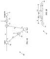
- FIG. 1B illustrates a physical model for the relay channel in accordance with the present invention
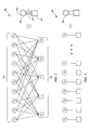
- FIG. 2 illustrates an exemplary factor graph representation of a regular Low-Density Parity Check (LDPC) code and its shorthand notation;
- LDPC Low-Density Parity Check
- FIG. 3 illustrates an exemplary factor graph representation where no coding is involved, and a corresponding shorthand notation that represents such a parallel connection;
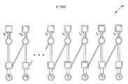
- FIG. 4 illustrates an exemplary factor graph representation of an optimal decoding algorithm in accordance with the present invention
- FIG. 5 illustrates an exemplary factor graph representation of a de-noising algorithm at the relay node in accordance with the present invention
- FIG. 6 illustrates an exemplary partial factor graph representation of backward and forward decoding schemes in accordance with the present invention
- FIG. 7 illustrates an exemplary sum-product decoding algorithm for use by the backward and forward decoding schemes of FIG. 6 ;
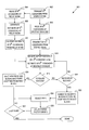
- FIG. 8 illustrates an exemplary method of partial factor graph decoding in accordance with the present invention.
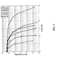
- FIG. 9 illustrates exemplary results obtained by the partial factor graph decoding techniques in accordance with the present invention.
- the present invention provides a code design technique for the relay channel and its associated factor graph decoding.
- the code design is based on two main theoretical results for the relay channel: 1) the decode-and-forward protocol; and 2) the estimate-and-forward protocol, the latter being a newly designed protocol in accordance with the present invention.
- the general coding technique and general joint factor graph decoding a specific code design based on the idea of LDPC codes is presented to illustrate advantages associated with the present invention.
- the present invention provides a simplified version of factor graph decoding for the relay channel, which exhibits sufficient simplicity to make real time implementation possible.
- One general idea in accordance with the present invention is to break the factor graph into partial factor graphs and sequentially solve the partial factor graphs to successively remove the interference.
- a modular code design for the relay channel and decoding algorithms is contemplated by the present invention and is based on a factor graph representation of the code. The code construction is performed in three steps: 1) protocol design; 2) constituent code design; and 3) allocation of optimal transmission power.
- the modular structure allows the code to be adapted to the channel condition and the properties of the transmission media.
- An optimal decoding scheme for the code is presented along with two additional sub-optimal decoding schemes, a forward and a backward decoding scheme, where each decoding scheme exhibits much lower complexity.
- the backward decoding scheme exploits the idea of the analytical decode-and-forward coding protocol and hence has good performance when the relay node is located relatively close to the source node, e.g., about half way or less between the source and destination nodes.
- the forward decoding scheme exploits the idea of the analytical estimate-and-forward protocol and hence has good performance when the relay node is located relatively far from the source node, e.g., about half way or more between the source and destination nodes.
- the constructed code using a low-complexity simple relay protocol in accordance with the present invention outperforms currently known code designs for the direct channel by achieving an Energy per Bit to Receiver Noise Variance ratio (E b /N 0 ) that is below the minimum required E b /N 0 of single-link transmission.
- the designed codes according to the present invention achieve a gap of less than 1 decibel (dB) from the Shannon limit (at a Bit Error Rate of 10 ⁇ 6 ) for the relay channel with a code length of only 2 ⁇ 10 4 bits.
- FIG. 1A illustrates Gaussian relay channel 100 , in which source node 102 intends to transmit information to destination node 104 by using the direct link between the node pair (source 102 /destination 104 ) and the help of relay node 106 , if an improvement in the achievable rate of transmission can be achieved. If relay node 106 can be effective to improve the desired rate of transmission, then link pairs (source 102 /relay 106 ) and (relay 106 /destination 104 ) are utilized to form such a relay channel.
- Relay channel 100 consists of an input, x 1 , a relay output, y 1 , a relay sender, x 2 , (which depends only upon the past values of y 1 ), and a channel output y.
- Variables h 0 , h 1 , and h 2 are inter-channel gains and are assumed to be constant, while z and z 1 are independent Gaussian noise terms having zero mean values and variance N and N 1 , respectively, where z ⁇ n(0, N) and z 1 ⁇ n(0, N 1 ).
- the input power constraints are given by E[x 1 2 ] ⁇ P 1 and E[x 2 2 ] ⁇ P 2 , where one problem associated with relay channel 100 is to find the capacity of the channel between source node 102 and destination node 104 so as to achieve the best performance for the code.
- Y 1(i ⁇ 1) for 1 ⁇ i ⁇ n
- Y 1i is the received signal at the relay node
- x 2i is the transmitted signal from the relay node at time i
- decoding function g Y n ⁇ M.
- the encoding functions x 1 ( • ), f i ( • ) and decoding function g( • ) are allowed to be stochastic functions.
- encoding is based only on the input message x 1 .
- relay channel code design requires the specification of a code design for the encoder at source node 102 , and a code design for the encoder at relay node 106 .
- a protocol the specific choice of the relay function
- the codes that are used at the source and relay nodes are referred to as the constituent codes.
- construction of the code for relay channel 100 in accordance with the present invention contains three major elements: protocol selection; constituent code selection; and power assignment.
- Relay channel model 150 of FIG. 1B is thus illustrated, which normalizes all distances based upon the distance between source node 152 and destination node 154 . That is to say that all distances are normalized to the source-destination distance of unity and for simplicity, relay node 156 is positioned along a straight line between source node 152 and destination node 154 at a distance, d, from source node 152 , which further establishes the relay-destination distance to be equal to 1 ⁇ d.
- the source node sends a new codeword w b .
- the relay node estimates the transmitted codeword, w b , from the source by using the relay's received signal in this block.
- the relay's estimate, w b ′ is the closest codeword to the received signal, which is then sent in block b+1 without the need to re-encode. It should be noted that if the source-relay link is good, w b ′ is most likely decoded correctly, thus resembling the decode-and-forward coding scheme. On the other hand, when the source-relay link is not good, w b ′ can be interpreted as the best estimate of the relay received signal, which resembles the estimate-and-forward coding scheme.
- the optimal decoding algorithm according to the present invention is to wait for the entire transmission of B blocks and then jointly decode all of the codewords that are transmitted by source node 102 , with the help of relay node 106 .
- two sub-optimal algorithms are presented, i.e., the forward and the backward decoding schemes, which exhibit very good performance with several orders of magnitude reduction in complexity as compared to the optimal decoding algorithm.
- the optimal design of the constituent codes depends on both the chosen protocol and their given power allocation.
- the family of irregular LDPC codes for example, exhibit very good performance, while allowing for code optimization and thus are excellent candidates for the implementation of the constituent codes. More importantly, the LDPC codes may be optimized jointly using two possible approximations of the density evolution method, i.e., the Gaussian approximation and the Erasure channel approximation.
- the power allocation ratio along with the possible power allocations across the B blocks of the transmission may be considered as parameters that may be used to further improve the transmission rate achievable through use of the code design.
- R information transfer rate in the discrete memoryless relay channel of FIG. 1A
- R may be expressed in terms of the channel parameters and the power constraints as follows: R ⁇ 1 2 ⁇ max ⁇ , 0 ⁇ ⁇ ⁇ 1 ⁇ min ⁇ ⁇ log ⁇ ( 1 + ( 1 - ⁇ 2 ) ⁇ ( ⁇ 0 + ⁇ 1 ) ⁇ P 1 ) , log ⁇ ( 1 + ⁇ 1 ⁇ P 1 + ⁇ 2 ⁇ P 2 + 2 ⁇ ⁇ ⁇ ⁇ 1 ⁇ ⁇ 2 ⁇ P 1 ⁇ P 2 ) ⁇ ( 1 )
- ⁇ 0 ⁇ ⁇ ⁇ ⁇ h 0 ⁇ 2 N 1
- ⁇ 1 ⁇ ⁇ ⁇ ⁇ h 1 ⁇ 2 N
- ⁇ ⁇ ⁇ 2 ⁇ ⁇ ⁇ h 2 ⁇ 2 N .
- parameter, ⁇ corresponds to the correlation factor between the channel input, X 1 , and the relay signal X 2 .
- ⁇ the correlation factor
- one of two schemes may be used by relay node 106 when performing a de-noising operation, such that the de-noising operation either conforms to a decode-and-forward scheme, or an estimate-and-forward scheme.
- the decode-and-forward scheme transmission occurs in several blocks of long codewords. In each block, some information is solely encoded for the reception at the relay, where the codeword length is long enough to allow almost error free decoding by the relay.
- the source and relay nodes cooperate in resolving the ambiguity at the destination node about the message sent during the previous block by using the information that is now shared between the source and relay nodes.
- the received SNR at the relay node is not as good as the received SNR at the destination node (i.e., ⁇ 1 > ⁇ 0 ), then there is no gain over direct transmission by using the decode-and-forward scheme even if the available power at the relay node is very large.
- an estimate of the received signal at the relay node may be used, where similarly to the decode-and-forward scheme, the estimate-and-forward scheme encodes using several blocks of a large codeword length.
- the primary difficulty of code construction for the relay channel that makes it inherently different from ordinary single-link code design is due to the distributed nature of coding in the source and relay nodes.
- one of the challenges is the design of the forwarding strategy at the relay node, while another challenge corresponds to the joint coding between the source and relay nodes.
- the forwarding strategy expresses how to build the relay transmit signal based on the past relay received signals.
- two codebooks should be generated, one to be used by the encoder at the source node, and one for the encoder at the relay node.
- a factor graph representation of the code consists of: 1) a vector of “variable nodes”, where each variable node corresponds to a column of the parity check matrix, H, and is denoted by circles; 2) a vector of “check nodes”, where each check node corresponds to a row of the parity check matrix, H, and is denoted by a square; and 3) connections between the check nodes and the variable nodes that correspond to a logic value of“1” in the corresponding row and column of the parity check matrix, H.
- Variable nodes 202 correspond to symbols, x 1 , x 2 , . . . , x 10 , where 6 of the 10 symbols are to be used in each LDPC codeword.
- codeword C Given a particular instance of codeword C, for example, one can verify whether C is valid by taking the modulo-2 sum (i.e., ⁇ ) of the binary variables that comprise codeword, C, as directed by equations (6) through (10). If each equation results in a binary sum of zero, then the codeword is considered to be valid.
- Symbol 206 represents the short-hand (i.e., symbolic) representation of a factor graph having vector variable node 208 , vector check node 210 , and parity check matrix 212 , which represents the connection between vector check node 210 and vector variable node 208 .
- each vector check node is simply equal to its respective vector variable node as illustrated by the series of parallel connections between the variable and check nodes.
- Symbol 302 illustrates the short-hand notation for this trivial case.
- factor graph 400 of the proposed code for relay coding in accordance with the present invention may be illustrated.
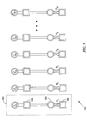
- Vectors r 1 , r 2 , . . . , and r B denote the received vectors in the 1 st , 2 nd , . . . , B th transmission blocks at the destination node.
- the parity check matrices of the constituent codes for the consecutive codewords in the B blocks are denoted by H 1 , H 2 , . . . , H B , respectively.
- Each codeword that is transmitted from the source in block b 1, 2, . . .
- the codeword w b which is encoded by the code having parity check matrix H b , affects both the received vectors r b and r b+1 at the destination node.
- a priori information about the codeword w b is obtained through both r b and r b+1 as illustrated in FIG. 4 .
- the optimal decoder at the destination node is the decoder that solves factor graph 400 to find all of the transmitted codewords jointly.
- factor graph 500 of FIG. 5 may be used to illustrate the code at the receiver of the relay node, where r′ 1 , r′ 2 , r′ 3 , . . . , and r′ B denote the received vectors in the 1 st , 2 nd , . . . , B th transmission blocks at the relay node.
- the relay node attempts to find the MAP estimate of the transmitted codeword from the source based on its received vector in the same block. This process is identical to solving factor graph 500 , although the goal is not necessarily to decode the transmitted codeword w b . In fact, for some relaying conditions, the transmission rate might be higher than the capacity of the source-relay link. In such an instance, the resulting codeword would be in error with high probability.
- the factor graph solver in this instance is a quantizer that quantizes the relay received vector with a rate that can be reliably transmitted over the relay-destination link.
- the factor graph solver in fact finds the closest codeword to the received signal, which corresponds to the center of the optimal region for the given quantizer.
- the output of the process is already a valid codeword, it is directly forwarded in the next block without the need to re-encode the information.
- the factor graph of the codes in different blocks are isolated, which provides a de-noising operation at the relay node that is much simpler than decoding at the destination node as depicted in FIG. 4 .
- joint decoding of all B blocks is performed by solving factor graph 400 using a MAP algorithm for an optimal decoding strategy.
- constituent codes e.g., H 2 and H 3
- H 2 and H 3 are chosen to be LDPC codes, however, then it is possible to use the practically implementable method of belief propagation as the optimal decoding strategy.
- the same method of belief propagation may also be extended for use where the constituent codes are either convolutional or turbo codes.
- the factor graph representation of these codes and their corresponding decoding schemes is known and will not be further discussed herein.
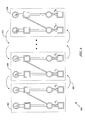
- the original factor graph of the code as illustrated in FIG. 4 is broken down into a sequence of smaller factor graphs 602 - 606 , called partial factor graphs, as exemplified in FIG. 6 .
- Two successive decoding schemes, the forward decoding scheme and the reverse decoding scheme may then be applied to the partial factor graphs 602 - 606 , each of which exhibit very good performance with orders of magnitude lower decoding complexity as compared to the joint decoding of all B blocks as illustrated in FIG. 4 .
- the constituent codes are some other form of block codes, such as turbo codes or convolutional codes, the same forward or backward decoding schemes can still be successfully exploited. The challenge remains, however, to find the optimal joint design of the block codes for the coding structures of FIG. 4 and FIG. 6 .
- decoding begins from the left to decode the first block and successively proceeds forward by removing the interference of the last decoded block from the current block.
- the decoding delay is no more than two blocks because the decoding of block, b, can be done right after reception of block, b+1.
- the performance of the forward decoding scheme is superior to the performance of the reverse decoding scheme, only when the position of the relay is far from the source (i.e., d>1 ⁇ d of FIG. 1B ).
- the forward decoding scheme in conjunction with the coding strategy of the present invention follows the idea of the information theoretical estimate-and-forward coding scheme for the relay channel.
- a simple calculation of the a priori bit probabilities of the codewords for the first partial factor graph 602 and the last partial factor graph 606 also confirms that the a priori information is stronger if decoding starts from partial factor graph 602 .
- the factor graph of FIG. 4 is again broken down into partial factor graphs 602 - 606 .
- the decoding starts from the rightmost partial factor graph 606 to decode the last block and successively proceeding backward, as indicated by directional arrows 610 , by removing the interference of the last decoded block from the current block.
- backward decoding is in fact more efficient for positions of the relay node closer to the source node (e.g., d ⁇ 1 ⁇ d of FIG. 1B ).
- the backward decoding scheme along with the coding strategy of the present invention follows the idea of the information theoretical decode-and-forward coding scheme for the relay channel.
- a simple calculation of the a priori bit probabilities of the codewords for the first partial factor graph 602 and the last partial factor graph 606 also confirms that the a priori information is stronger if decoding starts from partial factor graph 606 .
- the backward decoding scheme may be of more interest because the relay node that is positioned closer to the source node is generally more desirable. However, the backward decoding scheme exhibits a larger decoding delay, since decoding cannot start before receiving the entire block B transmission. Thus, the backward decoding scheme exhibits a decoding delay of at least B blocks, as opposed to the forward decoding scheme, which exhibits a decoding delay of only two blocks as discussed above.
- the decoding of the current block is performed by successive interference cancellation from the last decoded codeword followed by a solution to the resulting partial factor graphs.
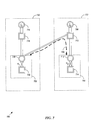
- the resulting partial factor graphs from the forward or backward decoding schemes after successive interference cancellation have an identical structure. Therefore, it is enough to discuss the partial factor graph 700 for the first and second blocks of transmission as exemplified in FIG. 7 .
- Vector variable nodes 716 and 708 represent two sets, or vectors, of variable nodes. Each of vector variable nodes 716 and 708 are connected in parallel to respective vector check nodes 718 and 710 , which are in turn connected in parallel to respective vector variable nodes 720 and 712 of parity check matrices H 1 and H 2 , respectively. The vector variable nodes 720 and 712 are connected in parallel to respective vector check nodes 722 and 714 of parity check matrices H 1 and H 2 .
- v 0)/p( r 1 ′
- v 1)).
- LLR r1′ first computes the conditional probabilities for each bit of received vector r 1 ′ given bit values of 0 and 1 and then the natural log of the ratio is computed to generate LLR r1′ .
- LLR r1′ is then transmitted by vector check node 504 to vector variable node 506 as a message via the parallel connection between vector check node 504 and vector variable node 506 .
- the message is then converted to bit probabilities by vector variable node 506 and then checked for compliance by vector check node 508 as defined by parity check matrix H 1 .
- Similar messages are then exchanged between vector check node 508 and vector variable node 506 , whereby the process is repeated using an iterative sum-product algorithm until a predetermined termination threshold has been reached.
- the predetermined termination threshold may be achieved in one of two ways. First, the iteration can proceed to the point at which there is complete compliance with parity check matrix H 1 , in which case the valid codeword has been successfully decoded. Second, a maximum number of iterations have been executed, but complete compliance with parity check matrix H 1 has not yet been reached. Thus, bit errors still exist within the received vector as compared to the transmitted codeword, resulting in a best estimate for the received codeword. The number of bit errors resulting in the best estimate is, nevertheless, an improvement upon the number of bit errors contained within the received vector and is, therefore, used. Once either of the two termination thresholds is reached, the received vector r 1 ′ is considered to be de-noised by the relay node, which results in either a perfect decode of the transmitted codeword, or at least a best estimate of the transmitted codeword.
- vector r 1 has been de-noised by the relay node, as discussed above, and is then forwarded onto the destination node by the relay node as codeword w 1 ′.
- vector r 2 represents a superposition of the de-noised codeword that is transmitted by the relay node, w 1 ′, with the newly transmitted codeword, w 2 , from the source node.
- vector check node 710 has three separate connections to each of the three neighbors of vector check node 710 and they are: vector variable node 708 ; vector variable node 720 ; and vector variable node 712 .
- Messages from each of the neighbors are sent to vector check node 710 during one iteration of the joint solution of factor graphs 730 and 732 .
- vector check node 710 calculates response messages (i.e., LLRs), to be sent to each of its neighbors during a second iteration. The process is then repeated using a sum-product algorithm until terminated in accordance with a predetermined termination rule.
- response messages i.e., LLRs
- the sum-product algorithm allows the computation of the a posteriori probability mass function, p(x i
- MAP Symbol-by-symbol maximum aposteriori
- g i (x i ) represents the joint aposteriori probability mass function.
- the sum-product algorithm therefore, is a procedure that is used to organize the simultaneous computation of marginals of equation (11), which ultimately either leads to finding the actual codeword, x i , or a best estimate for the codeword, x i ′.
- the sum-product algorithm may be understood as operating by passing messages over the edges of the factor graph (i.e., the connections between vector variable nodes and vector check nodes.)
- the messages are actually functions, which may be passed in either direction over the edge. That is to say that a message may be transmitted by a vector variable node to a vector check node, or by a vector check node to a vector variable node. Since each message is a function, they can be multiplied as functions. Thus, if ⁇ 1 (x) and ⁇ 2 (x) are messages that are functions of x, then their product ⁇ 1 (X)* ⁇ 2 (X) is also a well-defined function of x. Likewise, if ⁇ 1 (x) and ⁇ 2 (y) are messages that are functions of x and y, then their product ⁇ 1 (x)* ⁇ 2 (y) is also a well-defined function of the pair (x,y).
- the sum-product rule is defined in terms of two simple update rules: the vector variable node update rule and the vector check node update rule.
- the update rule for vector variable nodes states that the message sent from the vector variable node to the recipient vector check node is obtained by multiplying the messages received at the vector variable node from its neighbors other than the recipient vector check node. For example, message 706 that is sent to vector check node 710 from vector variable node 720 is the product of messages received at vector variable node 720 from vector check nodes 718 and 722 .
- the update rule for vector check nodes states that the message sent from the vector check node to the recipient vector variable node is obtained by multiplying the messages received at the vector check node from its neighbors other than the recipient vector node and then marginalizing the resulting function.
- message 706 that is sent to vector variable node 720 from vector check node 710 is the marginalized product of messages received at vector check node 710 from vector variable nodes 708 and 712 .
- any message passed over an edge that is incident on a variable, x is a function over the alphabet on which the variable is defined (i.e., a function of x). If, for example, x is a binary variable defined on the alphabet ⁇ 0,1 ⁇ , then messages passed on any edges incident on x will be a function of the form ⁇ (x).
- Such functions may be specified by the vector [ ⁇ (0), p(1)], or if scale is not important, by the ratios ⁇ (0)/ ⁇ (1) or log( ⁇ (0)/ ⁇ (1)).
- the goal of the sum-product algorithm as implemented in FIG. 7 is to decode both transmitted codewords, w 1 and w 2 , after reception of the corresponding vectors, r 1 and r 2 .
- bit probabilities for both w 1 and w 2 codewords are calculated based on received vectors, r 1 and r 2 .
- the joint decoding of both transmitted codewords w 1 and w 2 at the first and second blocks is performed iteratively by passing messages 706 between the two parts, 702 and 704 , through vector check node 710 .
- received vector r 1 is a result of the transmitted codeword, w 1 , from the source node.
- Received vector r 2 contains both the transmitted codeword, w 2 , from the source node, but also contains the re-transmitted, de-noised codeword, w 1 ′, as transmitted by the relay node.
- the joint decoding algorithm as illustrated in FIG. 7 utilizes two versions of received codeword, namely w, as received in block 730 from the source node and the superposition of w 2 and w 1 ′ as received in block 732 from the relay node.
- decoding of codeword w 1 is generally more precise than the decoding of codeword w 2 , since the “helper” codeword, w 1 ′, exists to enhance the decoding of codeword w 1 at block 730 .
- decoding of codeword w 2 is generally more precise than the decoding of codeword w 3 since in this case, the “helper” codeword, w 2 ′, exists to enhance the decoding of codeword w 2 .
- advancement of the decoding scheme may occur from left to right, as is the case with the forward decoding scheme denoted by direction 608 of FIG. 6 , or conversely, advancement of the decoding scheme may occur from right to left, as is the case with the reverse decoding scheme denoted by direction 610 of FIG. 6 .
- block 704 iterates towards a solution for codeword w 2 based upon factor graph decoding of received vector r 2 using the sum-product method as discussed above.
- block 704 has received the de-noised codeword, w 1 ′, from the relay node.
- the LLR for de-noised codeword, w 1 ′ is then forwarded to vector variable node 720 of block 702 from vector check node 710 .
- vector variable node 720 is in receipt of both the LLR for received codeword, w 1 , from vector check node 718 , as well as the LLR for received codeword, w 1 ′, from vector check node 710 .
- the received codeword, w 1 , and the de-noised version of codeword w 1 are used by vector variable node 720 to improve the decoding solution for codeword w 1 .
- v_dec(1,num_v) is the decoded codeword mv_y(1,num_v) : is the Log Likelihood Ratio (LLR) of the received signal, defined as ln(p(y
- v 0)/p(y
- v 0)/p(e
- v 1)) sum_mv(1,num_v) : sum of all incoming messages to variable nodes sum_mc(num_c,1) : sum of all incoming messages to check nodes idx_v(num_edge,1) : index the variable node to which the edge is connected idx_c(num_edge,1) : index the check node to which the edge is connected %---------------
- codeword, w 1 has been decoded correctly with high probability and the estimate of codeword, w 2 , is very good.
- codeword w 2 is decoded correctly with high probability with an estimate of codeword, w 3 , being very good, and so on.
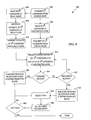
- FIG. 8 exemplifies steps that may be executed during the simplified factor graph decoding algorithm in accordance with the present invention.
- Each b th block is received at the destination and relay nodes as in steps 806 and 808 , respectively, where in step 808 , the relay node executes the de-noising process on the b th received codeword, which results in the estimate of the b th codeword (i.e., w b ′).
- w b ′ may represent a perfectly decoded codeword, or may represent a best estimate of the transmitted codeword, w b .
- codeword w b ′ is transmitted to the destination node in the b+1 block as in step 810 .
- codeword w b+1 is transmitted from the source node to the destination and relay nodes as in step 812 .
- the superposition of the estimated codeword, w b ′, and codeword w b+1 is received at the destination node as in step 814 .
- the forward or backward decoding scheme executes as soon as the first pairs of blocks (i.e., block b and b+1) is received at the destination node.
- the received B blocks are segmented into pairs starting from the last block as in step 822 , where the first pair selected corresponds to partial factor graph 606 of FIG. 6 as in step 824 .
- the paired factor graphs are then solved iteratively using the sum-product algorithm as discussed above as in step 828 .
- the forward decoding scheme is used, whereby the received B blocks are segmented into pairs starting from the first block as in step 820 .
- Forward decoding is then commenced by selecting the first pair as in step 824 , which corresponds to partial factor graph 602 of FIG. 6 . Both decoding methods are repeated until the entire B blocks of information have been decoded at the destination node.
- the backward decoding scheme imposes a decoding delay of at least B blocks, whereas the forward decoding scheme imposes a decoding delay of only two blocks.
- the backward decoding scheme exploits the idea of the analytical decode-and-forward coding protocol and hence has good performance when the relay node is located relatively close to the source node, e.g., about half way or less between the source and destination nodes.
- the forward decoding scheme exploits the idea of the analytical estimate-and-forward protocol and hence has good performance when the relay node is located relatively far from the source node, e.g., about half way or more between the source and destination nodes.
- the performance of both suboptimal decoding algorithms, forward decoding and backward decoding is shown. It can be seen that the designed code for the relay channel in accordance with the present invention can easily achieve 1-2 dB gain over the performance of the single user codes that do not use relaying for various positions of the relay node.
Abstract
A system and method of relay code design and factor graph decoding using a forward and a backward decoding scheme. The backward decoding scheme exploits the idea of the analytical decode-and-forward coding protocol and hence has good performance when the relay node is located relatively close to the source node. The forward decoding scheme exploits the idea of the analytical estimate-and-forward protocol and hence has good performance when the relay node is located relatively far from the source node. The optimal decoding factor graph is first broken into partial factor graphs and then solved iteratively using either the forward or backward decoding schemes.
Description
- This application claims the benefit of U.S. Provisional Application No. 60/575,877 filed 1 Jun. 2004, the content of which is incorporated herein by reference in its entirety.
- This invention relates in general to communication systems, and more particularly to a code design for a relay channel and its associated factor graph decoding.
- The past decade has been exciting in terms of the advances introduced in channel coding technology. Coding theory advancement is motivated by the lure of reliable communications over noisy channels at increasingly higher code rates. A central challenge with coding theory has always been to devise a coding scheme that comes close to achieving the channel capacity, while providing a practical level of decoding complexity.
- Advancements in coding theory have led to the development of code families such as turbo codes, Low-Density Parity Check (LDPC) codes, and others, that with simple iterative decoding algorithms, achieve performance very close to the Shannon limit on many important channels. The practical application of these codes has proliferated into the use of turbo-like codes in a wide variety of telecommunication standards and a variety of communication systems, such as the Cdma2000 High Rate Packet Data (HRPD) system also known as IS-856.
- As coding theory progresses, answers to questions like: “How should the sender encode information that is meant for different receivers in a common signal?”; and “What are the rates at which information can be sent to the different-receivers?” continue to be investigated for each transmission channel, but remain largely in the research domain of the generalized communication network. Such transmission channels of the generalized communication network include: the interference channel (i.e., two senders and two receivers with cross-talk); the two-way channel (i.e., two sender-receiver pairs sending information to each other); and the relay channel (i.e., one source node and one destination node, but with one or more intermediate sender-receiver pairs that act as relay nodes to facilitate the communication between the source node and the destination node.)
- It has been shown that the transmission rate of a communication network utilizing the relay channel may be greatly enhanced even beyond the transmission rate currently achievable through the use of Multiple Input Multiple Output (MIMO) systems. MIMO systems make use of multiple antennas at wireless transmitters and receivers to enable increased transmission rates over their respective wireless channels using space-time techniques. Another motivation for using a relay channel comes from the realization that in the case of a cellular network, for example, direct transmission between the base station and mobile terminals that are close to the cell boundary can be very expensive in terms of the transmission power required to insure reliable communications. Thus, relay stations appropriately placed may alleviate some of the transmit power requirements that are imposed by a single transmission link between the base station and the mobile terminal.
- In relay channel code design, one needs to specify a code design for the encoder at the source node, and a code design for the encoder at the relay node. Furthermore, the relay node initially does not have access to the message which is about to be transmitted through the relay channel, and so the relay node gathers the information gradually by observing the received symbols at the relay node through the source-relay link. The causality constraint forces the use of only the last received symbols at the relay node for the purpose of coding. Accordingly, the primary difficulty of code design for the relay channel, which makes it completely different from ordinary single link coding, is due to the importance of the design of an effective causal relaying function.
- One of the only techniques available today for relay channel code design is based on a turbo code. In this approach, each block of transmission is divided into two halves, where transmission of new information from the source node occurs only-during the first half. The source node then shuts off and transmission from the relay node occurs in the second half. While this technique improves upon multi-hopping, it nevertheless suffers from a considerable rate loss, since no new information is transmitted during the time that relaying is performed.
- Furthermore, while recent information theoretical results have shown a considerable improvement in the performance of communication systems through the use of relaying and cooperation, there has been almost no development in the area of real code design for the relay channel.
- Accordingly, there is a need in the communication industry for continued progress in coding alternatives for the relay channel, which allows concurrent transmission from the source node and the relay node. Such an alternative would serve to reduce the average power consumption without sacrificing the rate of transmission. The present invention fulfills these and other needs, and offers other advantages over prior art relay channel coding and decoding approaches.
- To overcome limitations in the prior art described above, and to overcome other limitations that will become apparent upon reading and understanding the present specification, the present invention discloses a system and method for a modular code design approach for the relay channel and corresponding decoding algorithms based on the factor graph representation of the code. The present invention allows concurrent transmission of information from the source node and the relay node, where each transmission is then decoded jointly at the destination node.
- In accordance with one embodiment of the invention, a relay channel comprises a source node that is adapted to transmit a plurality of codewords, a relay node that is coupled to receive the plurality of codewords and is adapted to transmit an estimate for each codeword received. The relay channel further comprises a destination node that is coupled to simultaneously receive a superposition of the plurality of codewords and estimates of the plurality of codewords and is adapted to decode each transmitted codeword using partial factor graph decoding. The codeword estimate improves the accuracy of the decoded codeword.
- In accordance with another embodiment of the invention, a method of forward decoding information blocks of a relay channel comprises receiving a first information block at a relay node and a destination node, estimating the first information block at the relay node, receiving a superposition of a second information block and the first information block estimate at the destination node, and jointly decoding the first and second information blocks at the destination node. The first information block estimate improves a decoding accuracy of the second information block.
- In accordance with another embodiment of the invention, a method of reverse decoding information blocks of a relay channel comprises receiving a predetermined number of information blocks at a relay node and a destination node, estimating the last information block received at the relay node, receiving a superposition of a next to last information block and the last information block estimate at the destination node, and jointly decoding the last and the next to last information blocks at the destination node. The last information block estimate improves a decoding accuracy of the next to last information block.
- These and various other advantages and features of novelty which characterize the invention are pointed out with particularity in the claims annexed hereto and form a part hereof. However, for a better understanding of the invention, its advantages, and the objects obtained by its use, reference should be made to the drawings which form a further part hereof, and to accompanying descriptive matter, in which there are illustrated and described representative examples of systems and methods in accordance with the invention.
- The invention is described in connection with the embodiments illustrated in the following diagrams.
-
FIG. 1A illustrates a general Gaussian relay channel in accordance with the present invention; -
FIG. 1B illustrates a physical model for the relay channel in accordance with the present invention; -
FIG. 2 illustrates an exemplary factor graph representation of a regular Low-Density Parity Check (LDPC) code and its shorthand notation; -
FIG. 3 illustrates an exemplary factor graph representation where no coding is involved, and a corresponding shorthand notation that represents such a parallel connection; -
FIG. 4 illustrates an exemplary factor graph representation of an optimal decoding algorithm in accordance with the present invention; -
FIG. 5 illustrates an exemplary factor graph representation of a de-noising algorithm at the relay node in accordance with the present invention; -
FIG. 6 illustrates an exemplary partial factor graph representation of backward and forward decoding schemes in accordance with the present invention; -
FIG. 7 illustrates an exemplary sum-product decoding algorithm for use by the backward and forward decoding schemes ofFIG. 6 ; -
FIG. 8 illustrates an exemplary method of partial factor graph decoding in accordance with the present invention; and -
FIG. 9 illustrates exemplary results obtained by the partial factor graph decoding techniques in accordance with the present invention. - A portion of the disclosure of this patent document contains material which is subject to copyright protection. The copyright owner has no objection to the facsimile reproduction by anyone of the patent document or the patent disclosure, as it appears in the Patent and Trademark Office patent file or records, but otherwise reserves all copyright rights whatsoever.
- In the following description of various exemplary embodiments, reference is made to the accompanying drawings which form a part hereof, and in which is shown by way of illustration various embodiments in which the invention may be practiced. It is to be understood that other embodiments may be utilized, as structural and operational changes may be made without departing from the scope of the present invention.
- Generally, the present invention provides a code design technique for the relay channel and its associated factor graph decoding. The code design is based on two main theoretical results for the relay channel: 1) the decode-and-forward protocol; and 2) the estimate-and-forward protocol, the latter being a newly designed protocol in accordance with the present invention. Besides the general coding technique and general joint factor graph decoding, a specific code design based on the idea of LDPC codes is presented to illustrate advantages associated with the present invention.
- In addition, the present invention provides a simplified version of factor graph decoding for the relay channel, which exhibits sufficient simplicity to make real time implementation possible. One general idea in accordance with the present invention is to break the factor graph into partial factor graphs and sequentially solve the partial factor graphs to successively remove the interference. In particular, a modular code design for the relay channel and decoding algorithms is contemplated by the present invention and is based on a factor graph representation of the code. The code construction is performed in three steps: 1) protocol design; 2) constituent code design; and 3) allocation of optimal transmission power. The modular structure allows the code to be adapted to the channel condition and the properties of the transmission media.
- An optimal decoding scheme for the code is presented along with two additional sub-optimal decoding schemes, a forward and a backward decoding scheme, where each decoding scheme exhibits much lower complexity. The backward decoding scheme exploits the idea of the analytical decode-and-forward coding protocol and hence has good performance when the relay node is located relatively close to the source node, e.g., about half way or less between the source and destination nodes. The forward decoding scheme exploits the idea of the analytical estimate-and-forward protocol and hence has good performance when the relay node is located relatively far from the source node, e.g., about half way or more between the source and destination nodes.
- For most of the relay channel conditions, the constructed code using a low-complexity simple relay protocol in accordance with the present invention outperforms currently known code designs for the direct channel by achieving an Energy per Bit to Receiver Noise Variance ratio (Eb/N0) that is below the minimum required Eb/N0 of single-link transmission. Moreover, the designed codes according to the present invention achieve a gap of less than 1 decibel (dB) from the Shannon limit (at a Bit Error Rate of 10−6) for the relay channel with a code length of only 2×104 bits.
-
FIG. 1A illustratesGaussian relay channel 100, in whichsource node 102 intends to transmit information todestination node 104 by using the direct link between the node pair (source 102/destination 104) and the help ofrelay node 106, if an improvement in the achievable rate of transmission can be achieved. Ifrelay node 106 can be effective to improve the desired rate of transmission, then link pairs (source 102/relay 106) and (relay 106/destination 104) are utilized to form such a relay channel. -
Relay channel 100 consists of an input, x1, a relay output, y1, a relay sender, x2, (which depends only upon the past values of y1), and a channel output y. The channel is assumed to be memoryless, where the dependency on the outputs is as follows: the channel output is y=h1×1+h2x2+z, and the relay output is given by y1=h0x1+z1. Variables h0, h1, and h2 are inter-channel gains and are assumed to be constant, while z and z1 are independent Gaussian noise terms having zero mean values and variance N and N1, respectively, where z≈n(0, N) and z1≈n(0, N1). The input power constraints are given by E[x1 2]≦P1 and E[x2 2]≦P2, where one problem associated withrelay channel 100 is to find the capacity of the channel betweensource node 102 anddestination node 104 so as to achieve the best performance for the code. - An (M,n) code for the Gaussian memoryless relay channel of
FIG. 1A consists of: a set of integers M={1,2, . . . , M}[1,M]; a set of encoding functions x1 n: M→Rn, where x1 n denotes an n-tuple (x11, x12, . . . , x1n); a set of relay functions {fi}i=1 n such that x2i=fi(Y11, Y12, . . . , Y1(i−1)) for 1≦i≦n where Y1i is the received signal at the relay node and x2i is the transmitted signal from the relay node at time i; and a decoding function g: Yn→M. For generality, the encoding functions x1(•), fi(•) and decoding function g(•) are allowed to be stochastic functions. At
source node 102, encoding is based only on the input message x1.Relay node 106, however, has no access to the input message and because of the non-anticipatory relay condition, relay signal x2i is allowed to depend only on the past y1 (i−1)=(y11, y12, . . . , y1(i−1)) values of the received signals. - As discussed above, relay channel code design requires the specification of a code design for the encoder at
source node 102, and a code design for the encoder atrelay node 106. As will be discussed in more detail below, the specific choice of the relay function is referred to as a protocol, and the codes that are used at the source and relay nodes are referred to as the constituent codes. Thus, construction of the code forrelay channel 100 in accordance with the present invention contains three major elements: protocol selection; constituent code selection; and power assignment. - In practice, the relay node position provides a better model for relay channel code evaluation as compared to the abstract relay channel parameters.
Relay channel model 150 ofFIG. 1B is thus illustrated, which normalizes all distances based upon the distance betweensource node 152 anddestination node 154. That is to say that all distances are normalized to the source-destination distance of unity and for simplicity,relay node 156 is positioned along a straight line betweensource node 152 anddestination node 154 at a distance, d, fromsource node 152, which further establishes the relay-destination distance to be equal to 1−d. - The channel gains may be expressed as
respectively. Normalization of the channel gain values, however, may also be normalized to the source-destination channel gain and subsequently related to the normalized distance parameter, d, as follows:
where α is the pathloss exponent and typically lies in the range between 2 and 5 and the set of channel gains (γ0, γ1, γ2) is assumed to be fixed over time. - The protocol element of relay channel code design in accordance with the present invention includes the transmission of information from
source node 102 in B equal length blocks b=1, 2, . . . , B. Every two consecutive blocks use two different block codes of length N each, which are called constituent codes. In a simple design, one may choose only two constituent codes that are used alternately in the blocks with an odd or even index. - At each block, b, the source node sends a new codeword w b. At the end of block, b, the relay node estimates the transmitted codeword, w b, from the source by using the relay's received signal in this block. The relay's estimate, w b′, is the closest codeword to the received signal, which is then sent in block b+1 without the need to re-encode. It should be noted that if the source-relay link is good, w b′ is most likely decoded correctly, thus resembling the decode-and-forward coding scheme. On the other hand, when the source-relay link is not good, w b′ can be interpreted as the best estimate of the relay received signal, which resembles the estimate-and-forward coding scheme.
- The optimal decoding algorithm according to the present invention is to wait for the entire transmission of B blocks and then jointly decode all of the codewords that are transmitted by
source node 102, with the help ofrelay node 106. In an alternate embodiment according to the present invention, two sub-optimal algorithms are presented, i.e., the forward and the backward decoding schemes, which exhibit very good performance with several orders of magnitude reduction in complexity as compared to the optimal decoding algorithm. - The set of constituent codes used in the source and relay nodes consists of all equal length codes, e.g., length=N, having the following parameters: 1) there are at least two constituent codes in the set; 2) each constituent code is chosen such that they have good performance in a single link channel; and 3) every pair of constituent codes has good performance in a multiple access channel where they are jointly decoded. The optimal design of the constituent codes depends on both the chosen protocol and their given power allocation. The family of irregular LDPC codes, for example, exhibit very good performance, while allowing for code optimization and thus are excellent candidates for the implementation of the constituent codes. More importantly, the LDPC codes may be optimized jointly using two possible approximations of the density evolution method, i.e., the Gaussian approximation and the Erasure channel approximation.
- It is, however, difficult to find the optimized LDPC code profile for the factor graph of the whole B blocks of transmission. Alternatively, good code designs are considered for the partial factor graph and will be discussed in more detail below. The resulting two sets of codes may then be used alternately over B transmitted blocks. Moreover, since the joint decoding of all B transmitted codewords is tedious, successive decoding algorithms are discussed below, which are optimized for use with the resulting two sets of codes.
- The power assignments for
relay channel 100 depend upon the channel parameters in addition to the relay protocol being used. Should the source and the relay channel share the available power (e.g., using a sum power constraint, P=P1+P2, where P1 is the power transmitted by the source node and P2 is the power transmitted by the relay node), an optimal ratio of the power allocation is found which achieves the best performance for the code. The power allocation ratio along with the possible power allocations across the B blocks of the transmission may be considered as parameters that may be used to further improve the transmission rate achievable through use of the code design. - An upper bound for the information transfer rate, R, in the discrete memoryless relay channel of
FIG. 1A may be expressed in terms of the channel parameters and the power constraints as follows:
where
The role of parameter, ρ, corresponds to the correlation factor between the channel input, X1, and the relay signal X2. For different channel parameters h0, h1, h2, N1, and N, there are different values of the correlation factor, ρ, which optimizes R of equation (1). It can be seen, therefore, that by introducing correlation between the channel input and relay signal, an increase in the information transfer rate may be achieved. - As discussed above, one of two schemes may be used by
relay node 106 when performing a de-noising operation, such that the de-noising operation either conforms to a decode-and-forward scheme, or an estimate-and-forward scheme. In the decode-and-forward scheme, transmission occurs in several blocks of long codewords. In each block, some information is solely encoded for the reception at the relay, where the codeword length is long enough to allow almost error free decoding by the relay. Thus, the source and relay nodes cooperate in resolving the ambiguity at the destination node about the message sent during the previous block by using the information that is now shared between the source and relay nodes. - The achievable rate of the decode-and-forward scheme for the Gaussian relay channel is given by:
whereas the achievable rate of the direct transmission for the Gaussian relay channel is given by:
Equations (2) and (3) above imply that if the relay node has a greater received Signal-to-Noise Ratio (SNR) with respect to the destination node's received SNR (i.e., γ0>γ1), then using the relay is helpful to improve the achievable rate of the direct transmission. If, however, the received SNR at the relay node is not as good as the received SNR at the destination node (i.e., γ1>γ0), then there is no gain over direct transmission by using the decode-and-forward scheme even if the available power at the relay node is very large. - In such an instance, an estimate of the received signal at the relay node may be used, where similarly to the decode-and-forward scheme, the estimate-and-forward scheme encodes using several blocks of a large codeword length. The achievable rate of the estimate-and-forward scheme for the Gaussian relay channel is given by:
By comparing equations (4) and (3), it is clear that the achievable rate, REF, of the estimate-and-forward scheme is always greater than the achievable rate, RDirect, of direct transmission. On the other hand, depending upon channel conditions, the decode-and-forward scheme may achieve a superior transmission rate over the estimate-and-forward scheme. - One of the most important aspects of code design for the relay channel, subject to the sum power constraint, is the optimal power allocation between the relay and source nodes. The power allocation is defined in terms of
which is the ratio of the relay power to the sum power of the source and relay. The optimal value, k, may be found by maximizing the rate of transmission given by equations (2) and (4) subject to the sum power constraint, P1+P2=P. - The primary difficulty of code construction for the relay channel that makes it inherently different from ordinary single-link code design is due to the distributed nature of coding in the source and relay nodes. Thus, one of the challenges is the design of the forwarding strategy at the relay node, while another challenge corresponds to the joint coding between the source and relay nodes. The forwarding strategy expresses how to build the relay transmit signal based on the past relay received signals. Furthermore, two codebooks should be generated, one to be used by the encoder at the source node, and one for the encoder at the relay node.
- As discussed above, the codes used in the decode-and-forward and the estimate-and-forward schemes may be described by a parity check matrix, H, and its associated factor graph. A factor graph representation of the code consists of: 1) a vector of “variable nodes”, where each variable node corresponds to a column of the parity check matrix, H, and is denoted by circles; 2) a vector of “check nodes”, where each check node corresponds to a row of the parity check matrix, H, and is denoted by a square; and 3) connections between the check nodes and the variable nodes that correspond to a logic value of“1” in the corresponding row and column of the parity check matrix, H.
- For example,
factor graph representation 200 ofFIG. 2 exhibiting a regular (3,6) LDPC code with rate ½ may be associated with the following parity check matrix:
Variable nodes 202 correspond to symbols, x1, x2, . . . , x10, where 6 of the 10 symbols are to be used in each LDPC codeword. There are also 5check nodes 204 that represent the binary linear equations that each codeword must satisfy. It can be seen by inspection that eachcheck node 204 hasdegree 6, while eachvariable node 202 hasdegree 3. - In a valid codeword, the neighbors of every check node 204 (i.e., the variables connected to the check node by a single edge) must form a configuration with a binary sum of zero (i.e., a configuration with an even number of logic ones.) In other words, for the (3,6) LDPC code, each
check node 204 corresponds to a binary sum ofvariable nodes 202 as follows:
x 1 ⊕x 2 ⊕x 3 ⊕x 4 ⊕x 5 ⊕x 6=0 (6)
x 1 ⊕x 2 ⊕x 3 ⊕x 7 ⊕x 8 ⊕x 9=0 (7)
x 1 ⊕x 4 ⊕x 6 ⊕x 7 ⊕x 8 ⊕x 10=0 (8)
x 2 ⊕x 5 ⊕x 6 ⊕x 8 ⊕x 9 ⊕x 10=0 (9)
x 3 ⊕x 4 ⊕x 5 ⊕x 7 ⊕x 9 ⊕x 10=0 (10)
where equations (6) through (10) correspond to the binary linear equations that each valid codeword must satisfy. Given a particular instance of codeword C, for example, one can verify whether C is valid by taking the modulo-2 sum (i.e., ⊕) of the binary variables that comprise codeword, C, as directed by equations (6) through (10). If each equation results in a binary sum of zero, then the codeword is considered to be valid.Symbol 206 represents the short-hand (i.e., symbolic) representation of a factor graph havingvector variable node 208,vector check node 210, andparity check matrix 212, which represents the connection betweenvector check node 210 andvector variable node 208. -
FIG. 3 exemplifiesfactor graph 300, whereby no coding is involved, i.e., H=I, where I is the identity matrix. In such an instance, each vector check node is simply equal to its respective vector variable node as illustrated by the series of parallel connections between the variable and check nodes.Symbol 302 illustrates the short-hand notation for this trivial case. - Through the use of the short-
hand notations FIGS. 2 and 3 ,factor graph 400 of the proposed code for relay coding in accordance with the present invention may be illustrated. Vectors r 1, r 2, . . . , and r B denote the received vectors in the 1st, 2nd, . . . , Bth transmission blocks at the destination node. The parity check matrices of the constituent codes for the consecutive codewords in the B blocks are denoted by H1, H2, . . . , HB, respectively. Each codeword that is transmitted from the source in block b=1, 2, . . . , B, is either decoded or estimated by the relay node and then retransmitted in the next block b+1. Therefore, the codeword w b, which is encoded by the code having parity check matrix Hb, affects both the received vectors rb and rb+1 at the destination node. As such, a priori information about the codeword w b is obtained through both r b and r b+1 as illustrated inFIG. 4 . Thus, the optimal decoder at the destination node is the decoder that solvesfactor graph 400 to find all of the transmitted codewords jointly. - Additionally,
factor graph 500 ofFIG. 5 may be used to illustrate the code at the receiver of the relay node, where r′1, r′2, r′3, . . . , and r′B denote the received vectors in the 1st, 2nd, . . . , Bth transmission blocks at the relay node. At each block, b, the relay node attempts to find the MAP estimate of the transmitted codeword from the source based on its received vector in the same block. This process is identical to solvingfactor graph 500, although the goal is not necessarily to decode the transmitted codeword w b. In fact, for some relaying conditions, the transmission rate might be higher than the capacity of the source-relay link. In such an instance, the resulting codeword would be in error with high probability. - In this instance, while the codeword is not decoded correctly, it nevertheless results in a best estimate of the received codeword and is forwarded to the destination node to help the destination node calculate the initial probabilities of the codeword symbols. Thus, the factor graph solver in this instance is a quantizer that quantizes the relay received vector with a rate that can be reliably transmitted over the relay-destination link. The factor graph solver in fact finds the closest codeword to the received signal, which corresponds to the center of the optimal region for the given quantizer. Furthermore, since the output of the process is already a valid codeword, it is directly forwarded in the next block without the need to re-encode the information. It should be noted that the factor graph of the codes in different blocks are isolated, which provides a de-noising operation at the relay node that is much simpler than decoding at the destination node as depicted in
FIG. 4 . - In a first embodiment, joint decoding of all B blocks is performed by solving
factor graph 400 using a MAP algorithm for an optimal decoding strategy. If constituent codes, e.g., H2 and H3, are chosen to be LDPC codes, however, then it is possible to use the practically implementable method of belief propagation as the optimal decoding strategy. The same method of belief propagation may also be extended for use where the constituent codes are either convolutional or turbo codes. The factor graph representation of these codes and their corresponding decoding schemes is known and will not be further discussed herein. - In a second embodiment according to the present invention, the original factor graph of the code as illustrated in
FIG. 4 is broken down into a sequence of smaller factor graphs 602-606, called partial factor graphs, as exemplified inFIG. 6 . Two successive decoding schemes, the forward decoding scheme and the reverse decoding scheme, may then be applied to the partial factor graphs 602-606, each of which exhibit very good performance with orders of magnitude lower decoding complexity as compared to the joint decoding of all B blocks as illustrated inFIG. 4 . It should be noted that if the constituent codes are some other form of block codes, such as turbo codes or convolutional codes, the same forward or backward decoding schemes can still be successfully exploited. The challenge remains, however, to find the optimal joint design of the block codes for the coding structures ofFIG. 4 andFIG. 6 . - In the forward decoding scheme, as depicted by
directional arrows 608 ofFIG. 6 , decoding begins from the left to decode the first block and successively proceeds forward by removing the interference of the last decoded block from the current block. One inherent benefit of the forward decoding scheme, is that the decoding delay is no more than two blocks because the decoding of block, b, can be done right after reception of block,b+ 1. As discussed above, however, the performance of the forward decoding scheme is superior to the performance of the reverse decoding scheme, only when the position of the relay is far from the source (i.e., d>1−d ofFIG. 1B ). In such an instance, the forward decoding scheme in conjunction with the coding strategy of the present invention follows the idea of the information theoretical estimate-and-forward coding scheme for the relay channel. A simple calculation of the a priori bit probabilities of the codewords for the firstpartial factor graph 602 and the lastpartial factor graph 606 also confirms that the a priori information is stronger if decoding starts frompartial factor graph 602. - In the backward decoding scheme, the factor graph of
FIG. 4 is again broken down into partial factor graphs 602-606. However, the decoding starts from the rightmostpartial factor graph 606 to decode the last block and successively proceeding backward, as indicated bydirectional arrows 610, by removing the interference of the last decoded block from the current block. Despite the low decoding latency of the forward decoding scheme, backward decoding is in fact more efficient for positions of the relay node closer to the source node (e.g., d<1−d ofFIG. 1B ). The reason is that the backward decoding scheme along with the coding strategy of the present invention follows the idea of the information theoretical decode-and-forward coding scheme for the relay channel. A simple calculation of the a priori bit probabilities of the codewords for the firstpartial factor graph 602 and the lastpartial factor graph 606 also confirms that the a priori information is stronger if decoding starts frompartial factor graph 606. - The backward decoding scheme may be of more interest because the relay node that is positioned closer to the source node is generally more desirable. However, the backward decoding scheme exhibits a larger decoding delay, since decoding cannot start before receiving the entire block B transmission. Thus, the backward decoding scheme exhibits a decoding delay of at least B blocks, as opposed to the forward decoding scheme, which exhibits a decoding delay of only two blocks as discussed above.
- As discussed above, the decoding of the current block is performed by successive interference cancellation from the last decoded codeword followed by a solution to the resulting partial factor graphs. It should be noted that the resulting partial factor graphs from the forward or backward decoding schemes after successive interference cancellation have an identical structure. Therefore, it is enough to discuss the
partial factor graph 700 for the first and second blocks of transmission as exemplified inFIG. 7 . - Vector
variable nodes variable nodes vector check nodes variable nodes variable nodes vector check nodes - Vector r 1 represents the received signal at the destination node which pertains to the b=1 transmission block (i.e., w1) that is transmitted from the source node. It should be noted that the relay node also receives a vector relating to transmitted codeword w1 and it is denoted as r 1′, as illustrated for example, by
factor graph 502 ofFIG. 5 , where vector r 1′ subsequently undergoes a de-noising process. In particular, once vector r 1′ has been received by the relay node,vector check node 504 computes the Log Likelihood Ratio of the received vector r 1′ (LLRr1′), where LLRr1′=ln(p(r 1′|v=0)/p(r 1′|v=1)). The LLRr1′ first computes the conditional probabilities for each bit of received vector r 1′ given bit values of 0 and 1 and then the natural log of the ratio is computed to generate LLRr1′. - LLRr1′ is then transmitted by
vector check node 504 tovector variable node 506 as a message via the parallel connection betweenvector check node 504 andvector variable node 506. The message is then converted to bit probabilities byvector variable node 506 and then checked for compliance byvector check node 508 as defined by parity check matrix H1. Similar messages are then exchanged betweenvector check node 508 andvector variable node 506, whereby the process is repeated using an iterative sum-product algorithm until a predetermined termination threshold has been reached. - The predetermined termination threshold may be achieved in one of two ways. First, the iteration can proceed to the point at which there is complete compliance with parity check matrix H1, in which case the valid codeword has been successfully decoded. Second, a maximum number of iterations have been executed, but complete compliance with parity check matrix H1 has not yet been reached. Thus, bit errors still exist within the received vector as compared to the transmitted codeword, resulting in a best estimate for the received codeword. The number of bit errors resulting in the best estimate is, nevertheless, an improvement upon the number of bit errors contained within the received vector and is, therefore, used. Once either of the two termination thresholds is reached, the received vector r 1′ is considered to be de-noised by the relay node, which results in either a perfect decode of the transmitted codeword, or at least a best estimate of the transmitted codeword.
- Vector r 2 represents the received signal at the destination node which pertains to the b=2 transmission block (i.e., w 2) that is transmitted from the source node. By the time w 2 has been transmitted by the source node, however, vector r 1 has been de-noised by the relay node, as discussed above, and is then forwarded onto the destination node by the relay node as codeword w 1′. Thus, vector r 2 represents a superposition of the de-noised codeword that is transmitted by the relay node, w 1′, with the newly transmitted codeword, w 2, from the source node.
- In contrast to the solution of
factor graph 502 ofFIG. 5 as discussed above, a joint solution offactor graphs FIG. 7 must be accomplished, sincevector variable node 720 offactor graph 730 is a neighbor tovector check node 710 offactor graph 732 as denoted by the parallel connection between the two nodes. Thus, received vector r2 has a direct impact on the decoding process of received vector r1 due tomessages 706 that are exchanged betweenvector check node 710 andvector variable node 720. - In fact,
vector check node 710 has three separate connections to each of the three neighbors ofvector check node 710 and they are:vector variable node 708;vector variable node 720; andvector variable node 712. Messages from each of the neighbors are sent tovector check node 710 during one iteration of the joint solution offactor graphs vector check node 710 then calculates response messages (i.e., LLRs), to be sent to each of its neighbors during a second iteration. The process is then repeated using a sum-product algorithm until terminated in accordance with a predetermined termination rule. - Generally speaking, the sum-product algorithm allows the computation of the a posteriori probability mass function, p(xi|y), where in the case of
factor graph 732 ofFIG. 7 , y represents the received vector, r 2, and xi represents a valid codeword as defined by parity check matrix H2. Symbol-by-symbol maximum aposteriori (MAP) decoding requires such a computation, so that the most likely value for xi may be selected. However, since there are many valid codewords corresponding to parity check matrix, H2, the joint a posteriori probability mass function must be calculated, which requires a marginalization operation of the form:
where gi(xi) represents the joint aposteriori probability mass function. The sum-product algorithm, therefore, is a procedure that is used to organize the simultaneous computation of marginals of equation (11), which ultimately either leads to finding the actual codeword, xi, or a best estimate for the codeword, xi′. - The sum-product algorithm may be understood as operating by passing messages over the edges of the factor graph (i.e., the connections between vector variable nodes and vector check nodes.) The messages are actually functions, which may be passed in either direction over the edge. That is to say that a message may be transmitted by a vector variable node to a vector check node, or by a vector check node to a vector variable node. Since each message is a function, they can be multiplied as functions. Thus, if μ1(x) and μ2(x) are messages that are functions of x, then their product μ1(X)*μ2(X) is also a well-defined function of x. Likewise, if μ1(x) and μ2(y) are messages that are functions of x and y, then their product μ1(x)*μ2(y) is also a well-defined function of the pair (x,y).
- The sum-product rule is defined in terms of two simple update rules: the vector variable node update rule and the vector check node update rule. The update rule for vector variable nodes states that the message sent from the vector variable node to the recipient vector check node is obtained by multiplying the messages received at the vector variable node from its neighbors other than the recipient vector check node. For example,
message 706 that is sent tovector check node 710 fromvector variable node 720 is the product of messages received atvector variable node 720 fromvector check nodes - Similarly, the update rule for vector check nodes states that the message sent from the vector check node to the recipient vector variable node is obtained by multiplying the messages received at the vector check node from its neighbors other than the recipient vector node and then marginalizing the resulting function. For example,
message 706 that is sent tovector variable node 720 fromvector check node 710 is the marginalized product of messages received atvector check node 710 from vectorvariable nodes - Generally, any message passed over an edge that is incident on a variable, x, is a function over the alphabet on which the variable is defined (i.e., a function of x). If, for example, x is a binary variable defined on the alphabet {0,1}, then messages passed on any edges incident on x will be a function of the form μ(x). Such functions may be specified by the vector [μ(0), p(1)], or if scale is not important, by the ratios μ(0)/μ(1) or log(μ(0)/μ(1)).
- The goal of the sum-product algorithm as implemented in
FIG. 7 , is to decode both transmitted codewords, w 1 and w 2, after reception of the corresponding vectors, r1 and r2. Once the first and second blocks of transmission are received at the destination node, bit probabilities for both w 1 and w 2 codewords are calculated based on received vectors, r 1 and r 2. Then, the joint decoding of both transmitted codewords w 1 and w 2 at the first and second blocks is performed iteratively by passingmessages 706 between the two parts, 702 and 704, throughvector check node 710. - It should be noted, that received vector r 1 is a result of the transmitted codeword, w 1, from the source node. Received vector r 2, on the other hand, contains both the transmitted codeword, w 2, from the source node, but also contains the re-transmitted, de-noised codeword, w 1′, as transmitted by the relay node. Thus, the joint decoding algorithm as illustrated in
FIG. 7 utilizes two versions of received codeword, namely w, as received inblock 730 from the source node and the superposition of w2 and w 1′ as received inblock 732 from the relay node. Thus, decoding of codeword w 1 is generally more precise than the decoding of codeword w 2, since the “helper” codeword, w 1′, exists to enhance the decoding of codeword w 1 atblock 730. - As the algorithm advances to jointly decode the next pair of received vectors (i.e., r 2 and r 3) as exemplified by
partial factor graph 604 ofFIG. 6 , decoding of codeword w 2 is generally more precise than the decoding of codeword w 3 since in this case, the “helper” codeword, w 2′, exists to enhance the decoding of codeword w 2. It should be noted that advancement of the decoding scheme may occur from left to right, as is the case with the forward decoding scheme denoted bydirection 608 ofFIG. 6 , or conversely, advancement of the decoding scheme may occur from right to left, as is the case with the reverse decoding scheme denoted bydirection 610 ofFIG. 6 . - In particular, during the factor graph solution of
block 732, block 704 iterates towards a solution for codeword w 2 based upon factor graph decoding of received vector r 2 using the sum-product method as discussed above. In addition, block 704 has received the de-noised codeword, w 1′, from the relay node. The LLR for de-noised codeword, w 1′, is then forwarded tovector variable node 720 ofblock 702 fromvector check node 710. Thus,vector variable node 720 is in receipt of both the LLR for received codeword, w 1, fromvector check node 718, as well as the LLR for received codeword, w 1′, fromvector check node 710. As such, the received codeword, w 1, and the de-noised version of codeword w 1 (i.e., w 1′) are used byvector variable node 720 to improve the decoding solution for codeword w 1. - In order to more fully illustrate the joint decoding solution illustrated by
FIG. 7 , the following code sequence is presented, which is to be understood as a joint decoding solution where y is equal to the received vector, r 2. A declaration of variables, along with their respective meanings, is first provided in code segment (12) as follows:%--------------------------------------------------------------------- % Declaration of variables (12) %--------------------------------------------------------------------- num_v : is the number of variable nodes in each constituent code y(1,num_v) : is the received signal (e.g., y = r2) x(1,num_v) : is the received signal if there was no noise. v_dec(1,num_v) : is the decoded codeword mv_y(1,num_v) : is the Log Likelihood Ratio (LLR) of the received signal, defined as ln(p(y|v=0)/p(y|v=1)) mc(num_edge,1) : is the message to check nodes for a given edge mv(num_edge,1) : is the message to variable nodes for a given edge, where the messages are LLRs given by LLR = ln(p(e|v=0)/p(e|v=1)) sum_mv(1,num_v) : sum of all incoming messages to variable nodes sum_mc(num_c,1) : sum of all incoming messages to check nodes idx_v(num_edge,1) : index the variable node to which the edge is connected idx_c(num_edge,1) : index the check node to which the edge is connected %--------------------------------------------------------------------- % Initialization of the variables %--------------------------------------------------------------------- mv=zeros(1,length(idx_c)); // initialize mv for the code 1 and mv_2 for mv_2=zeros(1,length(idx_c2)); // the code 2 // priorSij means prior probability that each bit of wi is equal to j priorS10 = 0.5; priorS11 = 0.5; // set all prior probabilities of the bits for // each codeword to ½, since priorS20 = 0.5; priorS21 = 0.5; // no prior probability is known // prob_x_ij means that the probability that x = a1*i + a2*j given that the // received signal r2 is equal to y. // prob_x_00 is the probability that source node has sent a 0 and the relay // node has also sent a 0 prob_x_00 = const*exp(−((y−(a1+a2)){circumflex over ( )}2)/(2*var_noise)); // prob_x_10 is the probability that source node has sent a 1 and the relay // node has sent a 0 prob_x_10 = const*exp(−((y−(−a1+a2)){circumflex over ( )}2)/(2*var_noise)); // prob_x_01 is the probability that source node has sent a 0 and the relay // node has sent a 1 prob_x_01 = const*exp(−((y−(a1−a2)){circumflex over ( )}2)/(2*var_noise)); // prob_x_11 is the probability that source node has sent a 1 and the relay // node has also sent a 1 prob_x_11 = const*exp(−((y−(−a1−a2)){circumflex over ( )}2)/(2*var_noise)); // gammainSij is the probability that each bit of wi is equal to j gammainS10 = 0.5; // this value is initially ½ but the next time it // will be calculated from the messages which come gammainS11 = 0.5; // from the vector variable node 712 relating to the // second codeword w2 %--------------------------------------------------------------------- % One iteration over the code of 704 which corresponds (13) % to codeword w_2 and parity check matrix H2 %--------------------------------------------------------------------- %------Calculation of Messages from vector checknode 710 to vector variable node 712 ------ // gammaoutSij is the probability that wi is equal to j gammaoutS20 = gammainS10*prob_x_00*priorS20 + gammainS11*prob_x_10*priorS20; gammaoutS21 = gammainS10*prob_x_01*priorS21 + gammainS11*prob_x_11*priorS21; // mv_y is simply the LLR which is calculated from the above equations. // mv_y is the message which is sent from vector check node 710 to // vector variable node 712 mv_y = log(gammaoutS20/gammaoutS21); %--------------------------------------------------------------------- % Send message to vector check node 714 %--------------------------------------------------------------------- % sparse matrix can be used to store messages % add all incoming messages to a variable node together sum_mv=full(sum(sparse(idx_c,idx_v,mv,num_c,num_v),1))+mv_y; % sum all rows of a col mc=sum_mv(idx_v)−mv; %--------------------------------------------------------------------- % Send message back from vector check node 714 % to vector check node 712 %--------------------------------------------------------------------- log_mc=log_table(mc); sum_log_mc=full(sum(sparse(idx_c,idx_v,log_mc,num_c,num_v),2)); log_mv=sum_log_mc(idx_c)−log_mc; mv=inv_log_table(log_mv); %--------------------------------------------------------------------- % One iteration over the code of 702 which corresponds (14) % to codeword w_1 and parity check matrix H1 %--------------------------------------------------------------------- %------Calculation of Messages from vector checknode 710 to vector variable node 720 ------ gammainS21 = log(1/(1+exp(mv))); // Converting the messages to bit gammainS20 = log(1 − 1/(1+exp(mv))); // probabilities // in this step gammainSij comes from the messages which are passed from // vector variable node 712 gammaoutS10 = gammainS20*prob_x_00*priorS10 + gammainS21*prob_x_01*priorS10; gammaoutS11 = gammainS20*prob_x_10*priorS11 + gammainS21*prob_x_11*priorS11; mv_y_2 = log(gammaoutS10/gammaoutS11); // We also have side information from the received vector r1 therefore // we find the message which comes from the node r1 // assume that r1 is equal to y1 // for k = 1 : 1 : num_v mv_y1(k) = log(prob( w1(k) = 0 | r1(k) = y1(k)) / prob( w1(k) = 1 | r1(k) = y1(k))); end %--------------------------------------------------------------------- % Send message to vector check node 722 %--------------------------------------------------------------------- % sparse matrix to store messages to v nodes % add all incoming messages to a variable node together sum_mv_2= full(sum(sparse(idx_c2,idx_v2,mv_2,num_c2,num_v2),1)) + mv_y_2 + mv_y1; % sum all rows of a col mc_2=sum_mv_2(idx_v2)−mv_2; %--------------------------------------------------------------------- % Send message back from vector check node 722 % to vector check node 720 %--------------------------------------------------------------------- log_mc_2=log_table(mc_2); sum_log_mc_2=full(sum(sparse(idx_c,idx_v,log_mc_2,num_c,num_v),2)); log_mv_2=sum_log_mc_2(idx_c)−log_mc; mv_2=inv_log_table(log_mv_2); %--------------------------------------------------------------------- % Finding the message from vector variable node 720 (15) % back to vector check node 710 %--------------------------------------------------------------------- gammainS21 = log(1/(1+exp(mv_2))); // Converting the messages to bit gammainS20 = log(1 − 1/(1+exp(mv_2))); // probabilities %--------------------------------------------------------------------- % RETURN TO iteration for w_2 in code segment (13) %---------------------------------------------------------------------
Code segments (13) and (14) are then repeated until a predetermined threshold is reached, which constitutes a solution of partial factor graph 602 (or equivalentlypartial factor graph 606 depending on whether a forward or reverse decoding scheme is used). Generally, once the predetermined threshold has been reached, codeword, w 1, has been decoded correctly with high probability and the estimate of codeword, w 2, is very good. During the subsequent solution ofpartial factor graph 604, as discussed above, codeword w 2 is decoded correctly with high probability with an estimate of codeword, w 3, being very good, and so on. -
FIG. 8 exemplifies steps that may be executed during the simplified factor graph decoding algorithm in accordance with the present invention. As discussed above, transmission from the source node occurs in B equal length blocks b=1, 2, . . . , B as instep 802. Each bth block is received at the destination and relay nodes as insteps step 808, the relay node executes the de-noising process on the bth received codeword, which results in the estimate of the bth codeword (i.e., wb′). Depending upon the quality of the received codeword at the relay node, wb′ may represent a perfectly decoded codeword, or may represent a best estimate of the transmitted codeword, wb. In any case, codeword wb′ is transmitted to the destination node in the b+1 block as instep 810. - Simultaneously with
step 810, codeword wb+1 is transmitted from the source node to the destination and relay nodes as instep 812. The superposition of the estimated codeword, wb′, and codeword wb+1 is received at the destination node as instep 814. Depending upon whether the forward or backward decoding scheme is implemented, as determined instep 816, either the entire B blocks of information is received at the destination node through successive operations ofsteps - In the case of the backward decoding scheme, the received B blocks are segmented into pairs starting from the last block as in
step 822, where the first pair selected corresponds topartial factor graph 606 ofFIG. 6 as instep 824. The paired factor graphs are then solved iteratively using the sum-product algorithm as discussed above as instep 828. Alternatively, the forward decoding scheme is used, whereby the received B blocks are segmented into pairs starting from the first block as instep 820. Forward decoding is then commenced by selecting the first pair as instep 824, which corresponds topartial factor graph 602 ofFIG. 6 . Both decoding methods are repeated until the entire B blocks of information have been decoded at the destination node. - It can be seen, therefore, that the backward decoding scheme imposes a decoding delay of at least B blocks, whereas the forward decoding scheme imposes a decoding delay of only two blocks. As discussed above, the backward decoding scheme exploits the idea of the analytical decode-and-forward coding protocol and hence has good performance when the relay node is located relatively close to the source node, e.g., about half way or less between the source and destination nodes. The forward decoding scheme, on the other hand, exploits the idea of the analytical estimate-and-forward protocol and hence has good performance when the relay node is located relatively far from the source node, e.g., about half way or more between the source and destination nodes.
-
FIG. 9 illustrates exemplary performance of the proposed relay codes with LDPC constituent code of length 20,000 bits and rate R=½ for different position of the relay node at ¼, ½, and ¾ of the distance between source and the destination. The performance of both suboptimal decoding algorithms, forward decoding and backward decoding is shown. It can be seen that the designed code for the relay channel in accordance with the present invention can easily achieve 1-2 dB gain over the performance of the single user codes that do not use relaying for various positions of the relay node. - The foregoing description of the exemplary embodiment of the invention has been presented for the purposes of illustration and description. It is not intended to be exhaustive or to limit the invention to the precise form disclosed. Many modifications and variations are possible in light of the above teaching. For example, while the constituent codes have been illustrated as LDPC codes, other code types may be used, such as convolutional or turbo codes with equivalent results. It is intended that the scope of the invention be limited not with this detailed description, but rather determined by the claims appended hereto.
Claims (21)
1. A relay channel, comprising:
a source node adapted to transmit a plurality of codewords;
a relay node coupled to receive the plurality of codewords and adapted to transmit an estimate for each codeword received; and
a destination node coupled to simultaneously receive a superposition of the plurality of codewords and estimates of the plurality of codewords and adapted to decode each transmitted codeword using partial factor graph decoding, wherein the codeword estimate improves the accuracy of the decoded codeword.
2. The relay channel of claim 1 , wherein the codewords transmitted by the source node are each selected from a different codebook.
3. The relay channel of claim 2 , wherein the codebook includes a constituent codebook that is jointly designed.
4. The relay channel of claim 1 , wherein the estimate transmitted by the relay node for each codeword is the codeword itself.
5. The relay channel of claim 1 , wherein the estimate transmitted for each codeword is the codeword estimated by a predetermined number of estimation iterations.
6. The relay channel of claim 1 , wherein power allocated to the source node transmitter and the relay node transmitter conforms to an optimal power allocation between the relay transmitter and the source transmitter.
7. The relay channel of claim 6 , wherein the optimal power allocation conforms to a ratio of the relay node transmission power to the sum of the relay node transmission power and the source node transmission power.
8. A method of forward decoding information blocks of a relay channel, the method comprising:
receiving a first information block at a relay node and a destination node;
estimating the first information block at the relay node;
receiving a superposition of a second information block and the first information block estimate at the destination node; and
jointly decoding the first and second information blocks at the destination node, wherein the first information block estimate improves a decoding accuracy of the second information block.
9. The method of claim 8 , wherein estimating the first information block at the relay node comprises:
computing the log likelihood ratio (LLR) of the first information block using a first vector check node;
converting the LLR of the first information block to bit probabilities using a first vector variable node;
checking the bit probabilities against a parity check matrix using a second vector check node; and
exchanging messages between the second vector check node and the first vector variable node until a predetermined termination threshold is reached.
10. The method of claim 9 , wherein the predetermined termination threshold is reached in response to complete compliance with the parity check matrix.
11. The method of claim 9 , wherein the predetermined termination threshold is reached in response to a predetermined number of iterations.
12. The method of claim 8 , wherein jointly decoding the first and second information blocks at the destination node comprises:
computing the log likelihood ratio (LLR) of the first information block using a first vector check node;
converting the LLR of the first information block to bit probabilities using a first vector variable node; and
checking the bit probabilities against a parity check matrix using a second vector check node.
13. The method of claim 12 , wherein jointly decoding the first and second information blocks at the destination node further comprises:
computing the log likelihood ratio (LLR) of the superposition of the second information block and the first information block estimate using a third vector check node;
converting the LLR of the superposition of the second information block and the first information block estimate to bit probabilities using a second vector variable node; and
checking the bit probabilities against a parity check matrix using a fourth vector check node.
14. The method of claim 13 , wherein jointly decoding the first and second information blocks at the destination node further comprises iteratively passing messages between the first and second vector variable nodes via the third vector check node until terminated by a predetermined termination rule.
15. A method of reverse decoding information blocks of a relay channel, the method comprising:
receiving a predetermined number of information blocks at a relay node and a destination node;
estimating the last information block received at the relay node;
receiving a superposition of a next to last information block and the last information block estimate at the destination node; and
jointly decoding the last and the next to last information blocks at the destination node, wherein the last information block estimate improves a decoding accuracy of the next to last information block.
16. The method of claim 15 , wherein estimating the last information block at the relay node comprises:
computing the log likelihood ratio (LLR) of the last information block using a first vector check node;
converting the LLR of the last information block to bit probabilities using a first vector variable node;
checking the bit probabilities against a parity check matrix using a second vector check node; and
exchanging messages between the second vector check node and the first vector variable node until a predetermined termination threshold is reached.
17. The method of claim 16 , wherein the predetermined termination threshold is reached in response to complete compliance with the parity check matrix.
18. The method of claim 16 , wherein the predetermined termination threshold is reached in response to a predetermined number of iterations.
19. The method of claim 15 , wherein jointly decoding the last and the next to last information blocks at the destination node comprises:
computing the log likelihood ratio (LLR) of the last information block using a first vector check node;
converting the LLR of the last information block to bit probabilities using a first vector variable node; and
checking the bit probabilities against a parity check matrix using a second vector check node.
20. The method of claim 19 , wherein jointly decoding the last and the next to last information blocks at the destination node further comprises:
computing the log likelihood ratio (LLR) of the superposition of the next to last information block and the last information block estimate using a third vector check node;
converting the LLR of the superposition of the next to last information block and the last information block estimate to bit probabilities using a second vector variable node; and
checking the bit probabilities against a parity check matrix using a fourth vector check node.
21. The method of claim 20 , wherein jointly decoding the last and the next to last information blocks at the destination node further comprises iteratively passing messages between the first and second vector variable nodes via the third vector check node until terminated by a predetermined termination rule.
Priority Applications (1)
| Application Number | Priority Date | Filing Date | Title |
|---|---|---|---|
| US11/094,778 US20050265387A1 (en) | 2004-06-01 | 2005-03-30 | General code design for the relay channel and factor graph decoding |
Applications Claiming Priority (2)
| Application Number | Priority Date | Filing Date | Title |
|---|---|---|---|
| US57587704P | 2004-06-01 | 2004-06-01 | |
| US11/094,778 US20050265387A1 (en) | 2004-06-01 | 2005-03-30 | General code design for the relay channel and factor graph decoding |
Publications (1)
| Publication Number | Publication Date |
|---|---|
| US20050265387A1 true US20050265387A1 (en) | 2005-12-01 |
Family
ID=35463180
Family Applications (1)
| Application Number | Title | Priority Date | Filing Date |
|---|---|---|---|
| US11/094,778 Abandoned US20050265387A1 (en) | 2004-06-01 | 2005-03-30 | General code design for the relay channel and factor graph decoding |
Country Status (3)
| Country | Link |
|---|---|
| US (1) | US20050265387A1 (en) |
| EP (1) | EP1751899A1 (en) |
| WO (1) | WO2005119957A1 (en) |
Cited By (31)
| Publication number | Priority date | Publication date | Assignee | Title |
|---|---|---|---|---|
| US20060036928A1 (en) * | 2004-08-13 | 2006-02-16 | The Directv Group, Inc. | Code design and implementation improvements for low density parity check codes for multiple-input multiple-output channels |
| WO2006020460A3 (en) * | 2004-08-13 | 2006-05-18 | Directv Group Inc | Code design and implementation improvements for low density parity check codes for multiple-input multiple-output channels |
| US20070168834A1 (en) * | 2002-07-03 | 2007-07-19 | Mustafa Eroz | Method and system for routing in low density parity check (LDPC) decoders |
| US20070190932A1 (en) * | 2006-02-10 | 2007-08-16 | Navini Networks, Inc. | Method and system for detecting messages using enhanced distributed signaling |
| US20070217541A1 (en) * | 2006-03-15 | 2007-09-20 | Zhixin Liu | Compress-forward Coding with N-PSK Modulation for the Half-duplex Gaussian Relay Channel |
| US20070277080A1 (en) * | 2004-09-27 | 2007-11-29 | Wen-Yi Wu | Method for decoding multiword information |
| US20070297498A1 (en) * | 2006-06-21 | 2007-12-27 | Lucent Technologies Inc. | Distributed transmission involving cooperation between a transmitter and a relay |
| WO2008015507A2 (en) * | 2006-08-03 | 2008-02-07 | Nokia Corporation | Variable rate soft information forwarding |
| US20080082895A1 (en) * | 2002-07-26 | 2008-04-03 | The Directv Group, Inc. | Method and system for generating low density parity check codes |
| WO2008109912A1 (en) * | 2007-03-14 | 2008-09-18 | The University Of Sydney | Distributed turbo coding and relaying protocols |
| US20080274692A1 (en) * | 2005-11-29 | 2008-11-06 | Peter Larsson | Scheduling in a Wireless Multi-Hop Relay Network |
| US20080298474A1 (en) * | 2007-05-31 | 2008-12-04 | Nokia Corporation | Distributed iterative decoding for co-operative diversity |
| US20090031191A1 (en) * | 2006-08-04 | 2009-01-29 | Yang Yang | Wyner-Ziv Coding Based on TCQ and LDPC Codes |
| US20090187811A1 (en) * | 2002-07-03 | 2009-07-23 | The Directv Group, Inc. | Method and system for providing low density parity check (ldpc) encoding |
| US20090252243A1 (en) * | 2008-04-02 | 2009-10-08 | Samsung Electronics Co., Ltd. | Method and apparatus for transmitting signals in a multi-hop wireless communication system |
| US20090252146A1 (en) * | 2008-04-03 | 2009-10-08 | Microsoft Corporation | Continuous network coding in wireless relay networks |
| US20100050043A1 (en) * | 2006-12-01 | 2010-02-25 | Commissariat A L'energie Atomique | Method and device for decoding ldpc codes and communication apparatus including such device |
| US7864869B2 (en) | 2002-07-26 | 2011-01-04 | Dtvg Licensing, Inc. | Satellite communication system utilizing low density parity check codes |
| CN101999218A (en) * | 2008-04-11 | 2011-03-30 | 艾利森电话股份有限公司 | Network coded data communication |
| US20110194400A1 (en) * | 2006-02-14 | 2011-08-11 | Nec Laboratories America, Inc. | Method of Using a Quantized Beamforming Matrix from Multiple Codebook Entries for Multiple-Antenna Systems |
| US8019020B1 (en) * | 2006-11-01 | 2011-09-13 | Marvell International Ltd. | Binary decoding for correlated input information |
| WO2011152900A3 (en) * | 2010-02-22 | 2012-01-26 | Benjamin Vigoda | Distributed factor graph system |
| US8145980B2 (en) | 2002-07-03 | 2012-03-27 | Dtvg Licensing, Inc. | Method and system for decoding low density parity check (LDPC) codes |
| US8181081B1 (en) | 2007-11-30 | 2012-05-15 | Marvell International Ltd. | System and method for decoding correlated data |
| US8196003B2 (en) | 2007-08-07 | 2012-06-05 | Samsung Electronics Co., Ltd. | Apparatus and method for network-coding |
| CN102761404A (en) * | 2011-04-26 | 2012-10-31 | 现代摩比斯株式会社 | Automotive terminal and communication method based on the same |
| US8473798B1 (en) * | 2009-03-20 | 2013-06-25 | Comtect EF Data Corp. | Encoding and decoding systems and related methods |
| CN104662852A (en) * | 2012-09-24 | 2015-05-27 | 阿尔卡特朗讯 | Methods and apparatuses for channel estimation in wireless networks |
| CN107196711A (en) * | 2017-05-02 | 2017-09-22 | 中国人民解放军信息工程大学 | The method and device of signal transmission |
| US20190238263A1 (en) * | 2017-09-26 | 2019-08-01 | Purdue Research Foundation | Transcoding wireless communication system |
| CN115021867A (en) * | 2022-06-01 | 2022-09-06 | 北京理工大学 | MIMO-LDPC efficient detection decoding method based on factor graph |
Families Citing this family (1)
| Publication number | Priority date | Publication date | Assignee | Title |
|---|---|---|---|---|
| CN110739975B (en) * | 2019-09-20 | 2021-06-11 | 华中科技大学 | Variable node multiplexing method of semi-random decoder |
Citations (5)
| Publication number | Priority date | Publication date | Assignee | Title |
|---|---|---|---|---|
| US5224120A (en) * | 1990-12-05 | 1993-06-29 | Interdigital Technology Corporation | Dynamic capacity allocation CDMA spread spectrum communications |
| US6198775B1 (en) * | 1998-04-28 | 2001-03-06 | Ericsson Inc. | Transmit diversity method, systems, and terminals using scramble coding |
| US7174495B2 (en) * | 2003-12-19 | 2007-02-06 | Emmanuel Boutillon | LDPC decoder, corresponding method, system and computer program |
| US7180892B1 (en) * | 1999-09-20 | 2007-02-20 | Broadcom Corporation | Voice and data exchange over a packet based network with voice detection |
| US7185270B2 (en) * | 2003-07-29 | 2007-02-27 | Broadcom Corporation | LDPC (low density parity check) coded modulation hybrid decoding |
-
2005
- 2005-03-30 US US11/094,778 patent/US20050265387A1/en not_active Abandoned
- 2005-04-01 WO PCT/IB2005/000874 patent/WO2005119957A1/en active Application Filing
- 2005-04-01 EP EP05718348A patent/EP1751899A1/en not_active Withdrawn
Patent Citations (5)
| Publication number | Priority date | Publication date | Assignee | Title |
|---|---|---|---|---|
| US5224120A (en) * | 1990-12-05 | 1993-06-29 | Interdigital Technology Corporation | Dynamic capacity allocation CDMA spread spectrum communications |
| US6198775B1 (en) * | 1998-04-28 | 2001-03-06 | Ericsson Inc. | Transmit diversity method, systems, and terminals using scramble coding |
| US7180892B1 (en) * | 1999-09-20 | 2007-02-20 | Broadcom Corporation | Voice and data exchange over a packet based network with voice detection |
| US7185270B2 (en) * | 2003-07-29 | 2007-02-27 | Broadcom Corporation | LDPC (low density parity check) coded modulation hybrid decoding |
| US7174495B2 (en) * | 2003-12-19 | 2007-02-06 | Emmanuel Boutillon | LDPC decoder, corresponding method, system and computer program |
Cited By (57)
| Publication number | Priority date | Publication date | Assignee | Title |
|---|---|---|---|---|
| US20070168834A1 (en) * | 2002-07-03 | 2007-07-19 | Mustafa Eroz | Method and system for routing in low density parity check (LDPC) decoders |
| US8145980B2 (en) | 2002-07-03 | 2012-03-27 | Dtvg Licensing, Inc. | Method and system for decoding low density parity check (LDPC) codes |
| US20090187811A1 (en) * | 2002-07-03 | 2009-07-23 | The Directv Group, Inc. | Method and system for providing low density parity check (ldpc) encoding |
| US7954036B2 (en) | 2002-07-03 | 2011-05-31 | Dtvg Licensing, Inc. | Method and system for providing low density parity check (LDPC) encoding |
| US7962830B2 (en) | 2002-07-03 | 2011-06-14 | Dtvg Licensing, Inc. | Method and system for routing in low density parity check (LDPC) decoders |
| US8095854B2 (en) | 2002-07-26 | 2012-01-10 | Dtvg Licensing, Inc. | Method and system for generating low density parity check codes |
| US7864869B2 (en) | 2002-07-26 | 2011-01-04 | Dtvg Licensing, Inc. | Satellite communication system utilizing low density parity check codes |
| US20080082895A1 (en) * | 2002-07-26 | 2008-04-03 | The Directv Group, Inc. | Method and system for generating low density parity check codes |
| WO2006020460A3 (en) * | 2004-08-13 | 2006-05-18 | Directv Group Inc | Code design and implementation improvements for low density parity check codes for multiple-input multiple-output channels |
| US20060036928A1 (en) * | 2004-08-13 | 2006-02-16 | The Directv Group, Inc. | Code design and implementation improvements for low density parity check codes for multiple-input multiple-output channels |
| US7725802B2 (en) | 2004-08-13 | 2010-05-25 | The Directv Group, Inc. | Code design and implementation improvements for low density parity check codes for multiple-input multiple-output channels |
| US8069398B2 (en) * | 2004-09-27 | 2011-11-29 | Mediatek Inc. | Method for decoding multiword information |
| US20070277080A1 (en) * | 2004-09-27 | 2007-11-29 | Wen-Yi Wu | Method for decoding multiword information |
| US20080274692A1 (en) * | 2005-11-29 | 2008-11-06 | Peter Larsson | Scheduling in a Wireless Multi-Hop Relay Network |
| US8135337B2 (en) * | 2005-11-29 | 2012-03-13 | Telefonaktiebolaget Lm Ericsson | Scheduling in a wireless multi-hop relay network |
| US8050622B2 (en) * | 2006-02-10 | 2011-11-01 | Cisco Technology, Inc. | Method and system for detecting messages using enhanced distributed signaling |
| US20070190932A1 (en) * | 2006-02-10 | 2007-08-16 | Navini Networks, Inc. | Method and system for detecting messages using enhanced distributed signaling |
| US8103312B2 (en) * | 2006-02-14 | 2012-01-24 | Nec Laboratories America, Inc. | Method of using a quantized beamforming matrix from multiple codebook entries for multiple-antenna systems |
| US20110194400A1 (en) * | 2006-02-14 | 2011-08-11 | Nec Laboratories America, Inc. | Method of Using a Quantized Beamforming Matrix from Multiple Codebook Entries for Multiple-Antenna Systems |
| US8363747B2 (en) * | 2006-03-15 | 2013-01-29 | The Texas A&M University System | Compress-forward coding with N-PSK modulation for the half-duplex gaussian relay channel |
| US20110161776A1 (en) * | 2006-03-15 | 2011-06-30 | The Texas A&M University System | Compress-forward coding with n-psk modulation for the half-duplex gaussian relay channel |
| US7912147B2 (en) * | 2006-03-15 | 2011-03-22 | The Texas A&M University System | Compress-forward coding with N-PSK modulation for the half-duplex Gaussian relay channel |
| US20070217541A1 (en) * | 2006-03-15 | 2007-09-20 | Zhixin Liu | Compress-forward Coding with N-PSK Modulation for the Half-duplex Gaussian Relay Channel |
| US9025641B2 (en) * | 2006-06-21 | 2015-05-05 | Alcatel Lucent | Distributed transmission involving cooperation between a transmitter and a relay |
| US20070297498A1 (en) * | 2006-06-21 | 2007-12-27 | Lucent Technologies Inc. | Distributed transmission involving cooperation between a transmitter and a relay |
| WO2008015507A2 (en) * | 2006-08-03 | 2008-02-07 | Nokia Corporation | Variable rate soft information forwarding |
| US7821980B2 (en) * | 2006-08-03 | 2010-10-26 | Nokia Corporation | Variable rate soft information forwarding |
| WO2008015507A3 (en) * | 2006-08-03 | 2008-04-24 | Nokia Corp | Variable rate soft information forwarding |
| US20080052608A1 (en) * | 2006-08-03 | 2008-02-28 | Arnab Chakrabarti | Variable rate soft information forwarding |
| US20090031191A1 (en) * | 2006-08-04 | 2009-01-29 | Yang Yang | Wyner-Ziv Coding Based on TCQ and LDPC Codes |
| US8207874B2 (en) | 2006-08-04 | 2012-06-26 | The Texas A&M University System | Wyner-Ziv coding based on TCQ and LDPC codes |
| US8019020B1 (en) * | 2006-11-01 | 2011-09-13 | Marvell International Ltd. | Binary decoding for correlated input information |
| US20100050043A1 (en) * | 2006-12-01 | 2010-02-25 | Commissariat A L'energie Atomique | Method and device for decoding ldpc codes and communication apparatus including such device |
| US8291284B2 (en) * | 2006-12-01 | 2012-10-16 | Commissariat A L'energie Atomique | Method and device for decoding LDPC codes and communication apparatus including such device |
| WO2008109912A1 (en) * | 2007-03-14 | 2008-09-18 | The University Of Sydney | Distributed turbo coding and relaying protocols |
| US20100091697A1 (en) * | 2007-03-14 | 2010-04-15 | The University Of Sydney | Ditributed turbo coding and relaying protocols |
| US8416730B2 (en) | 2007-03-14 | 2013-04-09 | University Of Sydney | Distributed turbo coding and relaying protocols |
| US8139512B2 (en) * | 2007-05-31 | 2012-03-20 | Nokia Corporation | Distributed iterative decoding for co-operative diversity |
| US20080298474A1 (en) * | 2007-05-31 | 2008-12-04 | Nokia Corporation | Distributed iterative decoding for co-operative diversity |
| US8196003B2 (en) | 2007-08-07 | 2012-06-05 | Samsung Electronics Co., Ltd. | Apparatus and method for network-coding |
| US8572454B1 (en) | 2007-11-30 | 2013-10-29 | Marvell International Ltd. | System and method for decoding correlated data |
| US8181081B1 (en) | 2007-11-30 | 2012-05-15 | Marvell International Ltd. | System and method for decoding correlated data |
| US8806289B1 (en) | 2007-11-30 | 2014-08-12 | Marvell International Ltd. | Decoder and decoding method for a communication system |
| US8321749B1 (en) | 2007-11-30 | 2012-11-27 | Marvell International Ltd. | System and method for decoding correlated data |
| US20090252243A1 (en) * | 2008-04-02 | 2009-10-08 | Samsung Electronics Co., Ltd. | Method and apparatus for transmitting signals in a multi-hop wireless communication system |
| US8345787B2 (en) * | 2008-04-02 | 2013-01-01 | Samsung Electronics Co., Ltd | Method and apparatus for transmitting signals in a multi-hop wireless communication system |
| US20090252146A1 (en) * | 2008-04-03 | 2009-10-08 | Microsoft Corporation | Continuous network coding in wireless relay networks |
| CN101999218A (en) * | 2008-04-11 | 2011-03-30 | 艾利森电话股份有限公司 | Network coded data communication |
| US8473798B1 (en) * | 2009-03-20 | 2013-06-25 | Comtect EF Data Corp. | Encoding and decoding systems and related methods |
| WO2011152900A3 (en) * | 2010-02-22 | 2012-01-26 | Benjamin Vigoda | Distributed factor graph system |
| US9412068B2 (en) | 2010-02-22 | 2016-08-09 | Analog Devices, Inc. | Distributed factor graph system |
| CN102761404A (en) * | 2011-04-26 | 2012-10-31 | 现代摩比斯株式会社 | Automotive terminal and communication method based on the same |
| CN104662852A (en) * | 2012-09-24 | 2015-05-27 | 阿尔卡特朗讯 | Methods and apparatuses for channel estimation in wireless networks |
| CN107196711A (en) * | 2017-05-02 | 2017-09-22 | 中国人民解放军信息工程大学 | The method and device of signal transmission |
| US20190238263A1 (en) * | 2017-09-26 | 2019-08-01 | Purdue Research Foundation | Transcoding wireless communication system |
| US10715278B2 (en) * | 2017-09-26 | 2020-07-14 | Purdue Research Foundation | Transcoding wireless communication system |
| CN115021867A (en) * | 2022-06-01 | 2022-09-06 | 北京理工大学 | MIMO-LDPC efficient detection decoding method based on factor graph |
Also Published As
| Publication number | Publication date |
|---|---|
| EP1751899A1 (en) | 2007-02-14 |
| WO2005119957A1 (en) | 2005-12-15 |
Similar Documents
| Publication | Publication Date | Title |
|---|---|---|
| US20050265387A1 (en) | General code design for the relay channel and factor graph decoding | |
| US8358679B2 (en) | Relay station for a mobile communication system | |
| US7716561B2 (en) | Multi-threshold reliability decoding of low-density parity check codes | |
| US9025641B2 (en) | Distributed transmission involving cooperation between a transmitter and a relay | |
| US20070168833A1 (en) | Apparatus and method for receiving signal in a communication system using a low density parity check code | |
| US9191156B2 (en) | Apparatus and method using matrix network coding | |
| US20050229087A1 (en) | Decoding apparatus for low-density parity-check codes using sequential decoding, and method thereof | |
| US20100091697A1 (en) | Ditributed turbo coding and relaying protocols | |
| EP2202904B1 (en) | A relay station and a decoder | |
| US11297657B2 (en) | Coded random access mechanism for communication networks | |
| JP4459904B2 (en) | Relay station and method for enabling reliable digital communication between two nodes in a wireless relay-based network | |
| US20080141079A1 (en) | Cooperative relaying using dirty paper coding | |
| Tehrani et al. | Sigsag: Iterative detection through soft message-passing | |
| Danieli et al. | Maximum mutual information vector quantization of log-likelihood ratios for memory efficient HARQ implementations | |
| CN109450594B (en) | Rate-free code degree distribution optimization method for uplink of cloud access network | |
| Sorensen et al. | Ripple design of LT codes for BIAWGN channels | |
| Huang et al. | Convergence analysis for channel-coded physical layer network coding in Gaussian two-way relay channels | |
| KR101145673B1 (en) | The method of encoding using lt code with specific structure and the method of encoding using raptor code based thereof | |
| KR101244303B1 (en) | Apparatus and method for receving transmitted signal in multiple antenna system | |
| Wang et al. | Physical-layer network-coding over block fading channels with root-LDA lattice codes | |
| Karkooti et al. | Cooperative communications using scalable, medium block-length LDPC codes | |
| Chen et al. | Joint iterative decoding for irregular-LDPC-based coded cooperation over a non-ideal relay channel | |
| Padmanabhan et al. | Minimum power based relay selection for orthogonal multiple access relay networks | |
| US20150055736A1 (en) | Method and apparatus for decoding received sequence | |
| Zribi et al. | Cooperative communication using turbo product codes with mutiple-source spatial and temporal correlations |
Legal Events
| Date | Code | Title | Description |
|---|---|---|---|
| AS | Assignment |
Owner name: NOKIA CORPORATION, FINLAND Free format text: ASSIGNMENT OF ASSIGNORS INTEREST;ASSIGNORS:KHOJASTEPOUR, MOHAMMAD ALI;AHMED, NASIR;AAZHANG, BEHNAAM;REEL/FRAME:016092/0766;SIGNING DATES FROM 20050520 TO 20050523 |
|
| STCB | Information on status: application discontinuation |
Free format text: ABANDONED -- FAILURE TO RESPOND TO AN OFFICE ACTION |