US20080212819A1 - Low noise microphone for use in windy environments and/or in the presence of engine noise - Google Patents
Low noise microphone for use in windy environments and/or in the presence of engine noise Download PDFInfo
- Publication number
- US20080212819A1 US20080212819A1 US11/846,235 US84623507A US2008212819A1 US 20080212819 A1 US20080212819 A1 US 20080212819A1 US 84623507 A US84623507 A US 84623507A US 2008212819 A1 US2008212819 A1 US 2008212819A1
- Authority
- US
- United States
- Prior art keywords
- microphone
- sound
- high frequency
- emitter
- mixed signal
- Prior art date
- Legal status (The legal status is an assumption and is not a legal conclusion. Google has not performed a legal analysis and makes no representation as to the accuracy of the status listed.)
- Granted
Links
Images


Classifications
-
- H—ELECTRICITY
- H04—ELECTRIC COMMUNICATION TECHNIQUE
- H04R—LOUDSPEAKERS, MICROPHONES, GRAMOPHONE PICK-UPS OR LIKE ACOUSTIC ELECTROMECHANICAL TRANSDUCERS; DEAF-AID SETS; PUBLIC ADDRESS SYSTEMS
- H04R1/00—Details of transducers, loudspeakers or microphones
- H04R1/08—Mouthpieces; Microphones; Attachments therefor
- H04R1/083—Special constructions of mouthpieces
- H04R1/086—Protective screens, e.g. all weather or wind screens
-
- H—ELECTRICITY
- H04—ELECTRIC COMMUNICATION TECHNIQUE
- H04R—LOUDSPEAKERS, MICROPHONES, GRAMOPHONE PICK-UPS OR LIKE ACOUSTIC ELECTROMECHANICAL TRANSDUCERS; DEAF-AID SETS; PUBLIC ADDRESS SYSTEMS
- H04R1/00—Details of transducers, loudspeakers or microphones
- H04R1/20—Arrangements for obtaining desired frequency or directional characteristics
- H04R1/32—Arrangements for obtaining desired frequency or directional characteristics for obtaining desired directional characteristic only
- H04R1/40—Arrangements for obtaining desired frequency or directional characteristics for obtaining desired directional characteristic only by combining a number of identical transducers
- H04R1/406—Arrangements for obtaining desired frequency or directional characteristics for obtaining desired directional characteristic only by combining a number of identical transducers microphones
-
- H—ELECTRICITY
- H04—ELECTRIC COMMUNICATION TECHNIQUE
- H04R—LOUDSPEAKERS, MICROPHONES, GRAMOPHONE PICK-UPS OR LIKE ACOUSTIC ELECTROMECHANICAL TRANSDUCERS; DEAF-AID SETS; PUBLIC ADDRESS SYSTEMS
- H04R2201/00—Details of transducers, loudspeakers or microphones covered by H04R1/00 but not provided for in any of its subgroups
- H04R2201/40—Details of arrangements for obtaining desired directional characteristic by combining a number of identical transducers covered by H04R1/40 but not provided for in any of its subgroups
- H04R2201/401—2D or 3D arrays of transducers
Definitions
- This invention relates to detecting acoustic signals, and more particularly to detecting low frequency acoustic signals in the presence of wind and/or engine noise.
- wind noise One problem with microphones used in the outdoors is wind noise. For example, when microphones are flown on airborne vehicles for the purpose of airborne acoustic data collection, wind noise limits sensitivity and reception in the desired frequency range. In particular, the observed wind noise exhibits a 1/f characteristic with frequency and a V 2 characteristic with velocity.
- An airborne platform for remote acoustic data collection poses an additional challenge to practical implementation, which is interference from engine noise, if data is to be collected when the aircraft is operating with an engine on.
- the amplitudes of engine sounds can be many times greater than those of the desired signals, placing severe constraints on microphone dynamic range and sensitivity.
- FIG. 1 illustrates typical measured wind noise for a conventional microphone equipped with a wind screen, over the frequency band from 50 Hz to 2000 Hz.
- FIG. 2 illustrates the up-conversion in frequency of the base band audio to the ultrasonic range in accordance with the invention.
- FIGS. 3A and 3B illustrate how the interaction length between the high frequency carrier and an incident sound field may be increased in a small volume.
- FIG. 4 illustrates an additional embodiment having a high frequency sound field generated by top and bottom transducers.
- FIG. 5 illustrates an additional embodiment having orthogonal excitation and pickup paths.
- FIG. 6 illustrates the basic concept of using directionality characteristic of engine noise to reduce its effects.
- FIGS. 7A and 7B illustrate an example of a microphone designed to reduce the effects of engine noise.
- FIG. 8 illustrates the microphone of FIG. 7 installed on an airborne vehicle.
- the following description is directed to several embodiments of microphone systems capable of good operational performance under windy conditions.
- the microphone can be configured to also eliminate the effects of engine noise.
- a parametric (nonlinear) microphone described herein has spectral and directional properties that can inherently reject both wind noise and engine noise. These attributes are uniquely suited for the acquisition of airborne acoustic data from a UAV (unmanned airborne vehicle) flying at cruise speed with the engine running.
- UAV unmanned airborne vehicle
- FIG. 1 illustrates typical measured wind noise for a conventional microphone equipped with a wind screen, over the frequency band from 50 Hz to 2000 Hz.
- the strong 1/f nature of the wind noise is evident, with the noise amplitude dramatically increasing for frequencies below 500 Hz.
- this is the frequency range most desired for long range infrasonic collection and for collecting signature data from vehicles and machinery.
- the embodiments described herein are directed to a low noise microphone for use in windy environments.
- Typical applications include airborne acoustic collection from aerial platforms (such as UAVs, airplanes, and balloons), wind tunnels, and outdoor terrestrial locations with high ambient wind conditions.
- the microphone is particularly useful for applications in which the sounds desired to be detected are low frequency sounds, such that wind noise can become a severe problem.
- the microphones reduce interference from wind noise in the low frequency part of the audio spectrum. There are two salient points regarding this type of wind noise.
- the first point is that the noise is generated at the wind screen of the microphone.
- the wind noise depicted in FIG. 1 actually is generated by interaction of the wind and the microphone housing, which is typically a porous screen. More specifically, the noise results from turbulence caused by wind flow over the wind screen. The unperturbed air in front of the wind screen contains pristine audio uncontaminated by wind noise.
- the second point is that the wind noise decreases rapidly with increasing frequency.
- the wind noise is more than 40 dB less at 1500 Hz than it is at 50 Hz.
- the degradation of signal-to-wind noise-ratio is much more for low frequencies than for high frequencies.
- the microphones described herein reduce low frequency wind noise by sensing the desired acoustic sounds in the air where the air is quiet and undisturbed, prior to generation of the wind noise by turbulence. This is accomplished by translating the desired sounds up in frequency by nonlinear mixing in air with a high frequency carrier. The air itself becomes the nonlinear element that accomplishes the frequency translation. In the case of the typical microphone having a windscreen, the mixing occurs in front of the windscreen.
- Air is a compressible medium, and under high levels of acoustic excitation, the interaction of two sound waves becomes nonlinear and frequency mixing occurs.
- the nonlinear interaction (mixing) of the desired sounds with the high frequency carrier drives the air into nonlinear compression.
- the up-converted signals pass through the wind screen in the higher part of the spectrum where the wind noise is low. Demodulating the ultrasonic signals then recovers the desired signals without the wind noise.
- the carrier frequency is bounded on the high side by attenuation in the air and on the low side by (1) the actual frequency content of the desired sounds, and (2) the 1/f noise caused by the microphone windscreen.
- a typical audio of the desired sounds might extend up to 3000 Hz. Since an acoustic carrier would produce both upper and lower sidebands, the carrier frequency should be high enough so that the resulting lower sideband would not overlap the baseband signal. In this example any carrier frequency higher than 9000 Hz would do. So the lower bound for the carrier is twice the bandwidth of the baseband audio. If 1/f noise is present, the carrier frequency must also be high enough to be above it.
- a “high frequency carrier” is defined as a carrier meeting these criteria, and is often ultrasonic in frequency.
- FIG. 2 illustrates the up-conversion in frequency of the base band audio to an ultrasonic range, that is, nonlinear mixing in the frequency domain.
- the nonlinear process is analogous to amplitude modulation; the modulating signal (base band audio spectrum) appears as upper and lower sidebands about the carrier frequency.
- the upper and lower sidebands contain identical information but are mirrored in frequency content.
- Detection of the desired sounds is accomplished by passing the up-converted modulation sidebands through the wind screen in a frequency range wherein the 1/f wind noise has subsided to a low level. The sounds pass through the wind screen without the wind noise. Once the modulated spectra passes through the wind screen above the 1/f noise region, the desired sound information can be recovered through detection and various demodulation techniques. The latter may include synchronous or non-synchronous AM, DSB, or SSB demodulation techniques.
- a simple way to create the microphone is to illuminate the desired sound field with an ultrasonic flood, and then sense the scattered mixed signals with an ultrasonic receiving transducer.
- the magnitude of the interaction increases with the interaction length of the two sound waves.
- constraining the physical extent of the microphone to a smaller volume is often desirable.
- An example is airborne acoustic collection, where several microphones disposed along the wing and fuselage of an aircraft are desired so a steerable phased array can be implemented.
- FIGS. 3A and 3B illustrate how the interaction length between the high frequency (typically ultrasonic) carrier and an incident sound field may be increased in a small volume by folding the ultrasonic sound field back on itself many times. This can be accomplished using a single transducer and a planar reflector, as illustrated in FIG. 3A , or with two parallel transducers as illustrated in FIG. 3B .
- the effect is similar to an optical analog of a Fabry-Perot interferometer.
- the resulting standing wave can be considered as a continually reinforced reverberant beam, traversing the interaction zone in the center many times, increasing interaction length.
- the transducer spacing and phasing is coordinated to produce an optimized standing wave between the two transducers.
- the drive frequency and spacing of the transducer is coordinated to reinforce a standing wave.
- FIG. 3B In the embodiment of FIG. 3B , several transmit and receive topologies are possible.
- One transducer could transmit and the other receive in a simple pitch-catch arrangement.
- both transducers could both transmit and receive.
- electronic directional couplers could be used to separate the transmit and receive signal paths. Additional topologies are possible to take advantage of angle dependencies between sound fields.
- the windscreen need not be a wind screen of the conventional type.
- a smooth and non-porous surface for housing the “active” components of the microphone would be suitable.
- An “airpathless” microphone geometry would use a smooth non-porous surface backed by a cavity and the microphone components.
- FIG. 4 illustrates shows one embodiment of a microphone array 40 , in which an ultrasonic sound field is generated by an opposed pair of top and bottom transducers 41 .
- Base band audio enters the annularly disposed array of transducers from any angle and interacts with the ultrasonic sound field in the center.
- the four receiving transducers 42 are arranged at right angles to each other, and pick up the scattered and up-converted sounds in crossing orthogonal paths. The orthogonal paths are useful for more advanced signal processing capabilities.
- the receive paths are at 45-degrees to the excitation beams, and at least one receiving transducer 42 will always be in a good position to receive forward scatter.
- FIG. 5 illustrates an annular array 50 of orthogonal excitation and receiving transducers 51 .
- This topology is characterized by orthogonal excitation and pickup paths.
- Base band sounds enter the structure from any angle, including axially down the center.
- annular wind screen 55 made, for example, from acoustical foam.
- a further embodiment is to include additional transducers in additional planes. This would create a 3-dimensional structure resembling a sphere. Multiple excitation transducers would be useful in generating the intense ultrasonic sound field necessary for efficient mixing, and the multiple receiving transducers would help make the microphone omnidirectional.
- Engine noise is particularly difficult to overcome using conventional microphones, whose limitations stem primarily from their omnidirectionality and limited dynamic range. Their wide angular acceptance means that usually both noise from the desired emitter and the engine are in their field of view at the same time. Even if an adaptive noise cancellation signal could be obtained from the engine, few microphones possess the dynamic range required to separate the two signals.
- the property of the proposed microphone that can be used to defeat engine noise is extreme unidirectionality. Parametric modulation occurs only when the carrier and the baseband audio signals are co-propagating and aligned within a few degrees. If an array of correctly positioned microphones is mounted on an aircraft, the engine sounds interfere only with channels pointing directly at the engine. Radial channels out to the sides largely reject the engine sounds because they cross the ultrasonic interaction length at a large angle. The dual properties of wind noise immunity and engine noise rejection could enable high quality airborne acoustic collection in powered flight at cruise speeds.
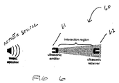
- FIG. 6 illustrates the basic concept of a proposed microphone, especially suited for reduction of engine noise.
- the microphone is an array of microphone elements; a single microphone element 60 is illustrated in FIG. 6 .
- An ultrasonic emitter 61 directs a narrow beam of ultrasonic energy towards an ultrasonic receiver 62 .
- Narrow beams are easy to achieve in the ultrasound region because the wavelength is small, and emitters and receivers can have effective apertures that are several wavelengths in diameter in a small physical size.
- the path is completely defined by the diameters of the emitter 61 and receiver 62 .
- Nonlinear interaction occurs when the two sound sources are co-propagating within narrow angular constraints in the same direction.
- This critical geometry is depicted in FIG. 6 by showing the sound source 63 inline but to the left of the ultrasonic transmitter-receiver pair.
- the amplitude of the parametric mixing products between co-propagating sound waves falls off sharply as a function of angular departure from co-axial.
- FIGS. 7A and 7B illustrate one example of a geometry for a microphone array 70 , suitable for engine-on use.
- FIG. 7A is a perspective view;
- FIG. 7B is a side view. Because of the narrow interaction angle required for parametric modulation, a number of radially disposed microphones is used to obtain a large acoustic search sector.
- the microphone array 70 has a radially emitting ultrasonic transmitter 71 surrounded by a circular array of ultrasonic receiving transducers 72 .
- the radial emitter 71 is positioned below the plane of the circular array 70 to establish a down tilt in the resulting coverage area. Sounds entering coverage area from below align with a radius from the central emitter 71 to one or more receivers 72 in the annulus.
- the number of receivers 72 is arbitrary.
- An example of a suitable array 70 has 60 receivers, which provide 360 degrees of azimuth coverage assuming an acceptance angle of 6 degrees per station.
- Angle-of-arrival information is deduced simply by correlation and interpolation of the receiver outputs.
- the down tilt angle could be adjusted by the geometry of array 70 to give the desired ground footprint for a specified cruising altitude.
- multiple central emitters that operate on different frequencies could be stacked vertically in the center of the array. This type of configuration would add elevation resolution to sensed data for precise emitter geolocation.
- FIG. 8 illustrates how the microphone array 70 of FIGS. 7A and 7B can be positioned above or below a UAV 80 . Because the circular array 70 is positioned wholly behind the engine 81 , only the paths originating from the tail looking forward through the propeller would be affected by engine noise. Excellent coverage could still be had to the rear and sides of the aircraft.
- the cross section of the array, radial emitter, and all support struts could be made with an appropriate airfoil shape to minimize drag and wind induced high frequency noise. Laboratory experiments have shown that good parametric modulation is obtained with an interaction length as little as 50 cm (about 11 ⁇ 2 feet). Thus, assembly of a suitable airborne microphone array could be accomplished on an aircraft of modest size.
Abstract
Description
- This application claims the benefit of U.S. Provisional Application No. 60/840,654, filed Aug. 28, 2006 and entitled “LOW NOISE MICROPHONE FOR USE IN WINDY ENVIRONMENTS.”
- This invention relates to detecting acoustic signals, and more particularly to detecting low frequency acoustic signals in the presence of wind and/or engine noise.
- One problem with microphones used in the outdoors is wind noise. For example, when microphones are flown on airborne vehicles for the purpose of airborne acoustic data collection, wind noise limits sensitivity and reception in the desired frequency range. In particular, the observed wind noise exhibits a 1/f characteristic with frequency and a V2 characteristic with velocity.
- An airborne platform for remote acoustic data collection poses an additional challenge to practical implementation, which is interference from engine noise, if data is to be collected when the aircraft is operating with an engine on. The amplitudes of engine sounds can be many times greater than those of the desired signals, placing severe constraints on microphone dynamic range and sensitivity.
- A more complete understanding of the present embodiments and advantages thereof may be acquired by referring to the following description taken in conjunction with the accompanying drawings, in which like reference numbers indicate like features, and wherein:
-
FIG. 1 illustrates typical measured wind noise for a conventional microphone equipped with a wind screen, over the frequency band from 50 Hz to 2000 Hz. -
FIG. 2 illustrates the up-conversion in frequency of the base band audio to the ultrasonic range in accordance with the invention. -
FIGS. 3A and 3B illustrate how the interaction length between the high frequency carrier and an incident sound field may be increased in a small volume. -
FIG. 4 illustrates an additional embodiment having a high frequency sound field generated by top and bottom transducers. -
FIG. 5 illustrates an additional embodiment having orthogonal excitation and pickup paths. -
FIG. 6 illustrates the basic concept of using directionality characteristic of engine noise to reduce its effects. -
FIGS. 7A and 7B illustrate an example of a microphone designed to reduce the effects of engine noise. -
FIG. 8 illustrates the microphone ofFIG. 7 installed on an airborne vehicle. - The following description is directed to several embodiments of microphone systems capable of good operational performance under windy conditions. The microphone can be configured to also eliminate the effects of engine noise.
- More specifically, for conditions of both wind and engine noise, a parametric (nonlinear) microphone described herein has spectral and directional properties that can inherently reject both wind noise and engine noise. These attributes are uniquely suited for the acquisition of airborne acoustic data from a UAV (unmanned airborne vehicle) flying at cruise speed with the engine running.
- Wind Noise Reduction
-
FIG. 1 illustrates typical measured wind noise for a conventional microphone equipped with a wind screen, over the frequency band from 50 Hz to 2000 Hz. The strong 1/f nature of the wind noise is evident, with the noise amplitude dramatically increasing for frequencies below 500 Hz. Unfortunately, this is the frequency range most desired for long range infrasonic collection and for collecting signature data from vehicles and machinery. - The embodiments described herein are directed to a low noise microphone for use in windy environments. Typical applications include airborne acoustic collection from aerial platforms (such as UAVs, airplanes, and balloons), wind tunnels, and outdoor terrestrial locations with high ambient wind conditions. The microphone is particularly useful for applications in which the sounds desired to be detected are low frequency sounds, such that wind noise can become a severe problem.
- More specifically, the microphones reduce interference from wind noise in the low frequency part of the audio spectrum. There are two salient points regarding this type of wind noise.
- The first point is that the noise is generated at the wind screen of the microphone. In the example of an airborne microphone on a UAV, if the UAV could suddenly stop its forward motion and listen at zero airspeed, there would be no wind noise. The wind noise depicted in
FIG. 1 actually is generated by interaction of the wind and the microphone housing, which is typically a porous screen. More specifically, the noise results from turbulence caused by wind flow over the wind screen. The unperturbed air in front of the wind screen contains pristine audio uncontaminated by wind noise. - The second point is that the wind noise decreases rapidly with increasing frequency. In
FIG. 1 for example, the wind noise is more than 40 dB less at 1500 Hz than it is at 50 Hz. The degradation of signal-to-wind noise-ratio is much more for low frequencies than for high frequencies. - The microphones described herein reduce low frequency wind noise by sensing the desired acoustic sounds in the air where the air is quiet and undisturbed, prior to generation of the wind noise by turbulence. This is accomplished by translating the desired sounds up in frequency by nonlinear mixing in air with a high frequency carrier. The air itself becomes the nonlinear element that accomplishes the frequency translation. In the case of the typical microphone having a windscreen, the mixing occurs in front of the windscreen.
- Air is a compressible medium, and under high levels of acoustic excitation, the interaction of two sound waves becomes nonlinear and frequency mixing occurs. The nonlinear interaction (mixing) of the desired sounds with the high frequency carrier drives the air into nonlinear compression. The up-converted signals pass through the wind screen in the higher part of the spectrum where the wind noise is low. Demodulating the ultrasonic signals then recovers the desired signals without the wind noise.
- The carrier frequency is bounded on the high side by attenuation in the air and on the low side by (1) the actual frequency content of the desired sounds, and (2) the 1/f noise caused by the microphone windscreen. For example, a typical audio of the desired sounds might extend up to 3000 Hz. Since an acoustic carrier would produce both upper and lower sidebands, the carrier frequency should be high enough so that the resulting lower sideband would not overlap the baseband signal. In this example any carrier frequency higher than 9000 Hz would do. So the lower bound for the carrier is twice the bandwidth of the baseband audio. If 1/f noise is present, the carrier frequency must also be high enough to be above it. For purposes of this description, a “high frequency carrier” is defined as a carrier meeting these criteria, and is often ultrasonic in frequency.
-
FIG. 2 illustrates the up-conversion in frequency of the base band audio to an ultrasonic range, that is, nonlinear mixing in the frequency domain. The nonlinear process is analogous to amplitude modulation; the modulating signal (base band audio spectrum) appears as upper and lower sidebands about the carrier frequency. The upper and lower sidebands contain identical information but are mirrored in frequency content. - Detection of the desired sounds is accomplished by passing the up-converted modulation sidebands through the wind screen in a frequency range wherein the 1/f wind noise has subsided to a low level. The sounds pass through the wind screen without the wind noise. Once the modulated spectra passes through the wind screen above the 1/f noise region, the desired sound information can be recovered through detection and various demodulation techniques. The latter may include synchronous or non-synchronous AM, DSB, or SSB demodulation techniques.
- In practice, a simple way to create the microphone is to illuminate the desired sound field with an ultrasonic flood, and then sense the scattered mixed signals with an ultrasonic receiving transducer. However, the magnitude of the interaction increases with the interaction length of the two sound waves. For low frequency sound detection, constraining the physical extent of the microphone to a smaller volume is often desirable. An example is airborne acoustic collection, where several microphones disposed along the wing and fuselage of an aircraft are desired so a steerable phased array can be implemented.
-
FIGS. 3A and 3B illustrate how the interaction length between the high frequency (typically ultrasonic) carrier and an incident sound field may be increased in a small volume by folding the ultrasonic sound field back on itself many times. This can be accomplished using a single transducer and a planar reflector, as illustrated inFIG. 3A , or with two parallel transducers as illustrated inFIG. 3B . - The effect is similar to an optical analog of a Fabry-Perot interferometer. The resulting standing wave can be considered as a continually reinforced reverberant beam, traversing the interaction zone in the center many times, increasing interaction length. In the two-transducer case (
FIG. 3B ), the transducer spacing and phasing is coordinated to produce an optimized standing wave between the two transducers. Similarly, in the case of a single transducer worked against a reflector (FIG. 3A ), the drive frequency and spacing of the transducer is coordinated to reinforce a standing wave. - In the embodiment of
FIG. 3B , several transmit and receive topologies are possible. One transducer could transmit and the other receive in a simple pitch-catch arrangement. Alternatively, both transducers could both transmit and receive. In this case, electronic directional couplers could be used to separate the transmit and receive signal paths. Additional topologies are possible to take advantage of angle dependencies between sound fields. - The windscreen need not be a wind screen of the conventional type. A smooth and non-porous surface for housing the “active” components of the microphone would be suitable. An “airpathless” microphone geometry would use a smooth non-porous surface backed by a cavity and the microphone components.
-
FIG. 4 illustrates shows one embodiment of a microphone array 40, in which an ultrasonic sound field is generated by an opposed pair of top andbottom transducers 41. Base band audio enters the annularly disposed array of transducers from any angle and interacts with the ultrasonic sound field in the center. The four receivingtransducers 42 are arranged at right angles to each other, and pick up the scattered and up-converted sounds in crossing orthogonal paths. The orthogonal paths are useful for more advanced signal processing capabilities. The receive paths are at 45-degrees to the excitation beams, and at least one receivingtransducer 42 will always be in a good position to receive forward scatter. -
FIG. 5 illustrates anannular array 50 of orthogonal excitation and receiving transducers 51. This topology is characterized by orthogonal excitation and pickup paths. Base band sounds enter the structure from any angle, including axially down the center. Also shown is anannular wind screen 55 made, for example, from acoustical foam. - A further embodiment is to include additional transducers in additional planes. This would create a 3-dimensional structure resembling a sphere. Multiple excitation transducers would be useful in generating the intense ultrasonic sound field necessary for efficient mixing, and the multiple receiving transducers would help make the microphone omnidirectional.
- In sum, the above-described embodiments have the following features: 1. A means to ameliorate low frequency wind noise by sensing the desired acoustic sounds in the air in front of a wind screen prior to generation of wind induced noise at the wind screen surface. 2. A means to detect acoustic sounds in a windy environment by translating the desired low frequency sounds up in frequency by nonlinear mixing in air with an ultrasonic carrier, and then passing the up-converted signals through the wind screen in the higher part of the spectrum where the wind noise is low. Demodulating the ultrasonic signals then recovers the desired signals but without the wind noise. 3. A means to increase the interaction length between the sensed acoustic signals and the up-converting ultrasonic carrier by folding the ultrasonic path back on itself between parallel reflectors and/or transducers. 4. A means to increase the non-linear interaction between the sensed low frequency acoustic signals and the up-converting ultrasonic carrier by use of an ultrasonic standing wave. 5. A means to reduce the dependence of interaction efficiency to angle of arrival by using multiple ultrasonic carrier beams that cross at a plurality of angles.
- Engine Noise Reduction
- Engine noise is particularly difficult to overcome using conventional microphones, whose limitations stem primarily from their omnidirectionality and limited dynamic range. Their wide angular acceptance means that usually both noise from the desired emitter and the engine are in their field of view at the same time. Even if an adaptive noise cancellation signal could be obtained from the engine, few microphones possess the dynamic range required to separate the two signals.
- The property of the proposed microphone that can be used to defeat engine noise is extreme unidirectionality. Parametric modulation occurs only when the carrier and the baseband audio signals are co-propagating and aligned within a few degrees. If an array of correctly positioned microphones is mounted on an aircraft, the engine sounds interfere only with channels pointing directly at the engine. Radial channels out to the sides largely reject the engine sounds because they cross the ultrasonic interaction length at a large angle. The dual properties of wind noise immunity and engine noise rejection could enable high quality airborne acoustic collection in powered flight at cruise speeds.
-
FIG. 6 illustrates the basic concept of a proposed microphone, especially suited for reduction of engine noise. As explained below in connection withFIGS. 7 and 8 , the microphone is an array of microphone elements; asingle microphone element 60 is illustrated inFIG. 6 . - An
ultrasonic emitter 61 directs a narrow beam of ultrasonic energy towards anultrasonic receiver 62. Narrow beams are easy to achieve in the ultrasound region because the wavelength is small, and emitters and receivers can have effective apertures that are several wavelengths in diameter in a small physical size. - In the pitch-catch configuration of
FIG. 6 , the path is completely defined by the diameters of theemitter 61 andreceiver 62. Nonlinear interaction occurs when the two sound sources are co-propagating within narrow angular constraints in the same direction. This critical geometry is depicted inFIG. 6 by showing the sound source 63 inline but to the left of the ultrasonic transmitter-receiver pair. - The amplitude of the parametric mixing products between co-propagating sound waves falls off sharply as a function of angular departure from co-axial.
- Experimentation indicates a 3-dB interaction angle to be less than +/−3 degrees. Even loud sounds crossing the ultrasound path at oblique angles are virtually undetectable. It is precisely this property that can be exploited to reject high-level engine noise.
-
FIGS. 7A and 7B illustrate one example of a geometry for amicrophone array 70, suitable for engine-on use.FIG. 7A is a perspective view;FIG. 7B is a side view. Because of the narrow interaction angle required for parametric modulation, a number of radially disposed microphones is used to obtain a large acoustic search sector. - The
microphone array 70 has a radially emittingultrasonic transmitter 71 surrounded by a circular array of ultrasonic receivingtransducers 72. Theradial emitter 71 is positioned below the plane of thecircular array 70 to establish a down tilt in the resulting coverage area. Sounds entering coverage area from below align with a radius from thecentral emitter 71 to one ormore receivers 72 in the annulus. The number ofreceivers 72 is arbitrary. An example of asuitable array 70 has 60 receivers, which provide 360 degrees of azimuth coverage assuming an acceptance angle of 6 degrees per station. - Angle-of-arrival information is deduced simply by correlation and interpolation of the receiver outputs. The down tilt angle could be adjusted by the geometry of
array 70 to give the desired ground footprint for a specified cruising altitude. - In enhanced embodiments, multiple central emitters that operate on different frequencies could be stacked vertically in the center of the array. This type of configuration would add elevation resolution to sensed data for precise emitter geolocation.
-
FIG. 8 illustrates how themicrophone array 70 ofFIGS. 7A and 7B can be positioned above or below aUAV 80. Because thecircular array 70 is positioned wholly behind theengine 81, only the paths originating from the tail looking forward through the propeller would be affected by engine noise. Excellent coverage could still be had to the rear and sides of the aircraft. - The cross section of the array, radial emitter, and all support struts could be made with an appropriate airfoil shape to minimize drag and wind induced high frequency noise. Laboratory experiments have shown that good parametric modulation is obtained with an interaction length as little as 50 cm (about 1½ feet). Thus, assembly of a suitable airborne microphone array could be accomplished on an aircraft of modest size.
Claims (22)
Priority Applications (1)
| Application Number | Priority Date | Filing Date | Title |
|---|---|---|---|
| US11/846,235 US8116482B2 (en) | 2006-08-28 | 2007-08-28 | Low noise microphone for use in windy environments and/or in the presence of engine noise |
Applications Claiming Priority (2)
| Application Number | Priority Date | Filing Date | Title |
|---|---|---|---|
| US84065406P | 2006-08-28 | 2006-08-28 | |
| US11/846,235 US8116482B2 (en) | 2006-08-28 | 2007-08-28 | Low noise microphone for use in windy environments and/or in the presence of engine noise |
Publications (2)
| Publication Number | Publication Date |
|---|---|
| US20080212819A1 true US20080212819A1 (en) | 2008-09-04 |
| US8116482B2 US8116482B2 (en) | 2012-02-14 |
Family
ID=39733086
Family Applications (1)
| Application Number | Title | Priority Date | Filing Date |
|---|---|---|---|
| US11/846,235 Active 2030-12-14 US8116482B2 (en) | 2006-08-28 | 2007-08-28 | Low noise microphone for use in windy environments and/or in the presence of engine noise |
Country Status (1)
| Country | Link |
|---|---|
| US (1) | US8116482B2 (en) |
Cited By (6)
| Publication number | Priority date | Publication date | Assignee | Title |
|---|---|---|---|---|
| EP3094113A1 (en) * | 2015-05-14 | 2016-11-16 | Harman International Industries, Inc. | Techniques for autonomously calibrating an audio system |
| US9600997B1 (en) * | 2015-11-03 | 2017-03-21 | International Business Machines Corporation | Localized flood alert system and method |
| US20180005643A1 (en) * | 2015-01-20 | 2018-01-04 | Dolby Laboratories Licensing Corporation | Modeling and Reduction of Drone Propulsion System Noise |
| US10225656B1 (en) | 2018-01-17 | 2019-03-05 | Harman International Industries, Incorporated | Mobile speaker system for virtual reality environments |
| US10377486B2 (en) | 2017-12-07 | 2019-08-13 | Harman International Industries, Incorporated | Drone deployed speaker system |
| US10837944B2 (en) | 2018-02-06 | 2020-11-17 | Harman International Industries, Incorporated | Resonator device for resonance mapping and sound production |
Families Citing this family (3)
| Publication number | Priority date | Publication date | Assignee | Title |
|---|---|---|---|---|
| US9489937B1 (en) * | 2014-03-07 | 2016-11-08 | Trace Live Network Inc. | Real-time noise reduction system for dynamic motor frequencies aboard an unmanned aerial vehicle (UAV) |
| EP3712635A1 (en) | 2014-08-29 | 2020-09-23 | SZ DJI Technology Co., Ltd. | An unmanned aerial vehicle (uav) for collecting audio data |
| US9877097B2 (en) | 2015-06-10 | 2018-01-23 | Motorola Solutions, Inc. | Slim-tunnel wind port for a communication device |
Citations (7)
| Publication number | Priority date | Publication date | Assignee | Title |
|---|---|---|---|---|
| US4039999A (en) * | 1976-02-17 | 1977-08-02 | John Weston | Communication system |
| US5812678A (en) * | 1996-02-26 | 1998-09-22 | Scalise; Stanley J. | Auscultation augmentation device |
| US6122384A (en) * | 1997-09-02 | 2000-09-19 | Qualcomm Inc. | Noise suppression system and method |
| US20050207590A1 (en) * | 1999-04-30 | 2005-09-22 | Wolfgang Niehoff | Method of reproducing audio sound with ultrasonic loudspeakers |
| US7127076B2 (en) * | 2003-03-03 | 2006-10-24 | Phonak Ag | Method for manufacturing acoustical devices and for reducing especially wind disturbances |
| US20070195968A1 (en) * | 2006-02-07 | 2007-08-23 | Jaber Associates, L.L.C. | Noise suppression method and system with single microphone |
| US20110129101A1 (en) * | 2004-07-13 | 2011-06-02 | 1...Limited | Directional Microphone |
Family Cites Families (2)
| Publication number | Priority date | Publication date | Assignee | Title |
|---|---|---|---|---|
| WO2002089525A2 (en) | 2001-04-27 | 2002-11-07 | Virginia Commonwealth University | Hearing device improvements using modulation techniques |
| WO2003019125A1 (en) | 2001-08-31 | 2003-03-06 | Nanyang Techonological University | Steering of directional sound beams |
-
2007
- 2007-08-28 US US11/846,235 patent/US8116482B2/en active Active
Patent Citations (7)
| Publication number | Priority date | Publication date | Assignee | Title |
|---|---|---|---|---|
| US4039999A (en) * | 1976-02-17 | 1977-08-02 | John Weston | Communication system |
| US5812678A (en) * | 1996-02-26 | 1998-09-22 | Scalise; Stanley J. | Auscultation augmentation device |
| US6122384A (en) * | 1997-09-02 | 2000-09-19 | Qualcomm Inc. | Noise suppression system and method |
| US20050207590A1 (en) * | 1999-04-30 | 2005-09-22 | Wolfgang Niehoff | Method of reproducing audio sound with ultrasonic loudspeakers |
| US7127076B2 (en) * | 2003-03-03 | 2006-10-24 | Phonak Ag | Method for manufacturing acoustical devices and for reducing especially wind disturbances |
| US20110129101A1 (en) * | 2004-07-13 | 2011-06-02 | 1...Limited | Directional Microphone |
| US20070195968A1 (en) * | 2006-02-07 | 2007-08-23 | Jaber Associates, L.L.C. | Noise suppression method and system with single microphone |
Cited By (12)
| Publication number | Priority date | Publication date | Assignee | Title |
|---|---|---|---|---|
| US20180005643A1 (en) * | 2015-01-20 | 2018-01-04 | Dolby Laboratories Licensing Corporation | Modeling and Reduction of Drone Propulsion System Noise |
| US10522166B2 (en) * | 2015-01-20 | 2019-12-31 | Dolby Laboratories Licensing Corporation | Modeling and reduction of drone propulsion system noise |
| US20200013424A1 (en) * | 2015-01-20 | 2020-01-09 | Dolby Laboratories Licensing Corporation | Modeling and reduction of drone propulsion system noise |
| US10909998B2 (en) * | 2015-01-20 | 2021-02-02 | Dolby Laboratories Licensing Corporation | Modeling and reduction of drone propulsion system noise |
| EP3094113A1 (en) * | 2015-05-14 | 2016-11-16 | Harman International Industries, Inc. | Techniques for autonomously calibrating an audio system |
| US10136234B2 (en) | 2015-05-14 | 2018-11-20 | Harman International Industries, Incorporated | Techniques for autonomously calibrating an audio system |
| US9600997B1 (en) * | 2015-11-03 | 2017-03-21 | International Business Machines Corporation | Localized flood alert system and method |
| US9773398B2 (en) | 2015-11-03 | 2017-09-26 | International Business Machines Corporation | Localized flood alert system |
| US10377486B2 (en) | 2017-12-07 | 2019-08-13 | Harman International Industries, Incorporated | Drone deployed speaker system |
| US11084583B2 (en) | 2017-12-07 | 2021-08-10 | Harman International Industries, Incorporated | Drone deployed speaker system |
| US10225656B1 (en) | 2018-01-17 | 2019-03-05 | Harman International Industries, Incorporated | Mobile speaker system for virtual reality environments |
| US10837944B2 (en) | 2018-02-06 | 2020-11-17 | Harman International Industries, Incorporated | Resonator device for resonance mapping and sound production |
Also Published As
| Publication number | Publication date |
|---|---|
| US8116482B2 (en) | 2012-02-14 |
Similar Documents
| Publication | Publication Date | Title |
|---|---|---|
| US8116482B2 (en) | Low noise microphone for use in windy environments and/or in the presence of engine noise | |
| US7423934B1 (en) | System for detecting, tracking, and reconstructing signals in spectrally competitive environments | |
| Sedunov et al. | Stevens drone detection acoustic system and experiments in acoustics UAV tracking | |
| US7551519B2 (en) | Passive long range acoustic sensor | |
| Sedunov et al. | UAV passive acoustic detection | |
| US20170219686A1 (en) | System and method for detecting aerial vehicle position and velocity via sound | |
| WO2005125267A2 (en) | Airborne collection of acoustic data using an unmanned aerial vehicle | |
| US5060206A (en) | Marine acoustic aerobuoy and method of operation | |
| US11442159B2 (en) | Multi-spectral THz micro-doppler radar based on silicon-based picosecond pulse radiators | |
| US11802955B2 (en) | Diversity fin antenna | |
| Blanchard et al. | Acoustic localization and tracking of a multi-rotor unmanned aerial vehicle using an array with few microphones | |
| US4719606A (en) | Process and device for passive detection of aircraft, namely helicopters | |
| Stinco et al. | Detection of envelope modulation and direction of arrival estimation of multiple noise sources with an acoustic vector sensor | |
| Sutin et al. | Acoustic detection, tracking and classification of low flying aircraft | |
| Calderan et al. | Low-frequency vocalizations of sei whales (Balaenoptera borealis) in the Southern Ocean | |
| Sedunov et al. | Long-term testing of acoustic system for tracking low-flying aircraft | |
| Traer et al. | Shallow-water seismoacoustic noise generated by tropical storms Ernesto and Florence | |
| CN106937227B (en) | Novel active microphone without vibrating diaphragm | |
| Salhi et al. | An array-based laser radar for UAV detection | |
| CN110138458A (en) | A kind of sound wave remotely orients pack transmitting implementation method | |
| de Bree et al. | Broad banded acoustic vector sensors for outdoor monitoring propeller driven aircraft | |
| CN108768340A (en) | L C frequency-selective filtering sonar receiving circuit | |
| FR2956907A1 (en) | Multistatic radar system for aircraft altitude measurement system to measure altitude of aircraft i.e. drone, located in approach zone of landing area, has antennas co-located in place of landing area to realize measurement of altitude | |
| Dafrallah et al. | Malicious UAV detection using various modalities | |
| Mandal et al. | Intruder Drone Detection using Unmanned Aerial Vehicle Borne Radar (UAVBR) via Reconfigurable Intelligent Reflective Surface (IRS) |
Legal Events
| Date | Code | Title | Description |
|---|---|---|---|
| AS | Assignment |
Owner name: SOUTHWEST RESEARCH INSTITUTE, TEXAS Free format text: ASSIGNMENT OF ASSIGNORS INTEREST;ASSIGNORS:CERWIN, STEPHEN A.;DENNIS, MARTIN G.;REEL/FRAME:019992/0779 Effective date: 20071008 |
|
| FEPP | Fee payment procedure |
Free format text: PAYOR NUMBER ASSIGNED (ORIGINAL EVENT CODE: ASPN); ENTITY STATUS OF PATENT OWNER: SMALL ENTITY |
|
| STCF | Information on status: patent grant |
Free format text: PATENTED CASE |
|
| FPAY | Fee payment |
Year of fee payment: 4 |
|
| MAFP | Maintenance fee payment |
Free format text: PAYMENT OF MAINTENANCE FEE, 8TH YR, SMALL ENTITY (ORIGINAL EVENT CODE: M2552); ENTITY STATUS OF PATENT OWNER: SMALL ENTITY Year of fee payment: 8 |
|
| MAFP | Maintenance fee payment |
Free format text: PAYMENT OF MAINTENANCE FEE, 12TH YR, SMALL ENTITY (ORIGINAL EVENT CODE: M2553); ENTITY STATUS OF PATENT OWNER: SMALL ENTITY Year of fee payment: 12 |