US20110060460A1 - Robot control apparatus - Google Patents
Robot control apparatus Download PDFInfo
- Publication number
- US20110060460A1 US20110060460A1 US12/597,958 US59795809A US2011060460A1 US 20110060460 A1 US20110060460 A1 US 20110060460A1 US 59795809 A US59795809 A US 59795809A US 2011060460 A1 US2011060460 A1 US 2011060460A1
- Authority
- US
- United States
- Prior art keywords
- torque
- calculation unit
- unit configured
- joint
- calculate
- Prior art date
- Legal status (The legal status is an assumption and is not a legal conclusion. Google has not performed a legal analysis and makes no representation as to the accuracy of the status listed.)
- Granted
Links
Images
Classifications
-
- B—PERFORMING OPERATIONS; TRANSPORTING
- B25—HAND TOOLS; PORTABLE POWER-DRIVEN TOOLS; MANIPULATORS
- B25J—MANIPULATORS; CHAMBERS PROVIDED WITH MANIPULATION DEVICES
- B25J9/00—Programme-controlled manipulators
- B25J9/16—Programme controls
- B25J9/1628—Programme controls characterised by the control loop
- B25J9/1633—Programme controls characterised by the control loop compliant, force, torque control, e.g. combined with position control
-
- G—PHYSICS
- G05—CONTROLLING; REGULATING
- G05B—CONTROL OR REGULATING SYSTEMS IN GENERAL; FUNCTIONAL ELEMENTS OF SUCH SYSTEMS; MONITORING OR TESTING ARRANGEMENTS FOR SUCH SYSTEMS OR ELEMENTS
- G05B2219/00—Program-control systems
- G05B2219/30—Nc systems
- G05B2219/39—Robotics, robotics to robotics hand
- G05B2219/39353—Joint space observer
-
- G—PHYSICS
- G05—CONTROLLING; REGULATING
- G05B—CONTROL OR REGULATING SYSTEMS IN GENERAL; FUNCTIONAL ELEMENTS OF SUCH SYSTEMS; MONITORING OR TESTING ARRANGEMENTS FOR SUCH SYSTEMS OR ELEMENTS
- G05B2219/00—Program-control systems
- G05B2219/30—Nc systems
- G05B2219/39—Robotics, robotics to robotics hand
- G05B2219/39355—Observer, disturbance observer
-
- G—PHYSICS
- G05—CONTROLLING; REGULATING
- G05B—CONTROL OR REGULATING SYSTEMS IN GENERAL; FUNCTIONAL ELEMENTS OF SUCH SYSTEMS; MONITORING OR TESTING ARRANGEMENTS FOR SUCH SYSTEMS OR ELEMENTS
- G05B2219/00—Program-control systems
- G05B2219/30—Nc systems
- G05B2219/41—Servomotor, servo controller till figures
- G05B2219/41374—Observe position and driving signal, predict, estimate disturbance signal
-
- G—PHYSICS
- G05—CONTROLLING; REGULATING
- G05B—CONTROL OR REGULATING SYSTEMS IN GENERAL; FUNCTIONAL ELEMENTS OF SUCH SYSTEMS; MONITORING OR TESTING ARRANGEMENTS FOR SUCH SYSTEMS OR ELEMENTS
- G05B2219/00—Program-control systems
- G05B2219/30—Nc systems
- G05B2219/41—Servomotor, servo controller till figures
- G05B2219/41387—Observe reference torque, position and feedback position, estimate contact force
Definitions
- the present invention relates to a robot control apparatus and a robot control method.
- a tip end such as an arm tip end portion of a robot (hereinafter, simply referred to as a “tip end”) controls a position and contact force thereof in a task coordinate system while contacting a subject
- the external force can be measured highly accurately.
- the force sensor is fragile against impact as well as is expensive, it is frequent that use of the force sensor is avoided.
- the force sensor In the case where the force sensor is not used, it is necessary to estimate external torque of an actuator, which is generated by an influence of the external force that acts on the robot, in order to estimate the external force.
- the external torque is calculated by estimating drive torque necessary for motion of the actuator and subtracting the estimated drive torque from an actual torque command value sent to a drive unit (amplifier).
- a method is known, which calculates the drive torque from a joint command for each joint, estimates the external torque from a difference between the calculated drive torque and the torque command value, and converts the estimated external torque into the external force in the task coordinate system (refer to Patent Literature 1 (JP 405-4984)).
- An object of the present invention is to provide a robot control apparatus and a robot control method, which can estimate an external force more highly accuracy and provide stable force control without using a force sensor.
- An aspect of the present invention inheres in a robot control apparatus controlling a robot having a joint shaft and a drive shaft transmitting a drive force from an actuator to the joint shaft, including: an angle detection unit configured to detect an angle of the drive shaft; a angle calculation unit configured to calculate an angle of the joint shaft from the angle of the drive shaft; a tip end position calculation unit configured to calculate a position of the robot from the angle of the joint shaft; a command value creation unit configured to create a position command value of the tip end position; an error calculation unit configured to calculate an error between the tip end position and the position command value; a difference calculation unit configured to calculate a joint angle difference from the error by inverse kinematic calculation; a command value calculation unit configured to calculate a torque command value by integrating the joint angle difference; a drive unit configured to drive the actuator based on the torque command value; a drive torque estimation unit configured to estimate a drive torque for driving the actuator from the angle of the joint shaft; an external torque calculation unit configured to calculate a difference between the estimated drive torque and the torque
- a robot control apparatus and a robot control method according to the present invention have the advantage that it is possible to estimate an external force more highly accuracy and provide stable force control without using a force sensor.
- FIG. 1 is a block diagram showing an example of a robot control apparatus according to an embodiment of the present invention.
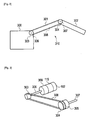
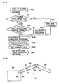
- FIG. 2 is a schematic view showing an example of control subject according to the embodiment.
- FIG. 3 is another schematic view showing the example of the control subject according to the embodiment.
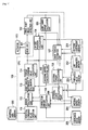
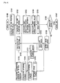
- FIG. 4 is a block diagram showing an example of a drive torque estimation unit according to the embodiment.
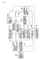
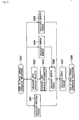
- FIG. 5 is a block diagram showing an example of an external force calculation unit according to the embodiment.
- FIG. 6 is a flowchart showing an example of a robot control method according to the embodiment.
- FIG. 7 is a flowchart showing an example of a drive torque estimation processing according to the embodiment.
- FIG. 8 is a flowchart showing an example of an external force calculation processing according to the embodiment.
- FIG. 9 is a block diagram showing an example of a robot control apparatus according to other embodiment of the present invention.
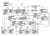
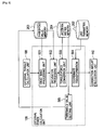
- a robot control apparatus includes a central processing unit (CPU) 100 , a drive unit (amplifier) 101 , a drive shaft angle detection unit 102 , a position data memory 200 , a friction coefficient memory 201 , a link parameter memory 202 , a threshold value memory 203 , a Jacobian matrix memory 204 and a compliance model memory 205 .
- a robot taken as an example of a control subject in the embodiment of the present invention includes a body 300 , and a movable portion 310 provided on the body 300 .
- the movable portion 310 has: a plurality of links 301 and 302 ; a plurality of joints 306 and 307 composed of a drive pulley 303 , a driven pulley 304 and the like; and a transmission mechanism 308 wound around the drive pulley 303 and the driven pulley 304 .
- the drive pulley 303 , a velocity reducer 309 , an actuator 115 and a drive shaft angle detection unit 102 are attached to the drive shaft (joint) 306 .
- the actuator 115 drives rotationally, and the velocity reducer 309 reduces the number of revolutions of the actuator 115 and increases torque thereof.
- the driven pulley 304 and a joint shaft angle detection unit 305 are attached to the joint shaft (joint) 307 .
- the drive shaft 306 rotates, whereby the joint shaft 307 is driven rotationally through the drive pulley 303 , the transmission mechanism (belt) 308 and the driven pulley 304 .
- a description will be made of the case of making control for the drive shaft 306 and the joint shaft 307 .
- a position sensor such as an encoder is usable.
- Each of the drive shaft angle detection unit 102 and the joint shaft angle detection unit 305 may include a filter that removes a predetermined frequency component.
- the drive shaft angle detection unit 102 detects a displacement amount (drive shaft angle) of a position of the drive shaft 306 .
- the joint shaft angle detection unit 305 detects a displacement amount (joint shaft angle) of a position of the joint shaft 307 .
- the CPU 100 shown in FIG. 1 logically includes an joint shaft angle calculation unit 103 , a top end position calculation unit 104 , a Jacobian matrix calculation unit 105 , an drive torque estimation unit 107 , an external torque calculation unit 108 , an external force calculation unit 109 , a correction amount calculation unit 110 , a position command value creation unit 111 , an error calculation unit 112 , a joint angle difference calculation unit 113 and a torque command value calculation unit 114 as modules (logic circuits) which are hardware resources.
- the joint shaft angle calculation unit 103 calculates the joint shaft angle from the drive shaft angle detected by the drive shaft angle detection unit 102 in response to a ratio of the drive shaft 306 and the joint shaft 307 , which is owned by the transmission mechanism 308 , and is such as a reduction ratio of the velocity reducer 309 .
- the joint shaft angle may be detected directly by the joint shaft angle detection unit 305 attached to the joint shaft 307 .
- the top end position calculation unit 104 reads out a link parameter from the link parameter memory 202 , and calculates a tip end position in a task coordinate system of the robot from the joint shaft angle, which is calculated by the joint shaft angle calculation unit 103 , by forward kinematic calculation by using the link parameter.
- the Jacobian matrix calculation unit 105 calculates a Jacobian matrix from the joint shaft angle calculated by the joint shaft angle calculation unit 103 , and stores the calculated Jacobian matrix in the Jacobian matrix memory 204 .
- the Jacobian matrix is a matrix that expresses a minute displacement relationship between the task coordinate system and joint coordinate system of the robot. Between an error
- the drive torque estimation unit 107 estimates drive torque, which is necessary to drive the joint shaft 307 of the robot, from the joint shaft angle calculated by the joint shaft angle calculation unit 103 .
- the drive torque estimation unit 107 includes a drive shaft velocity calculation unit 400 , a gravity torque calculation unit 403 , an inertia torque calculation unit 402 , a friction torque calculation unit 401 and an adding unit 404 .
- the drive shaft velocity calculation unit 400 calculates a drive shaft velocity by taking, for example, a time difference from the joint shaft angle calculated by the joint shaft angle calculation unit 103 .
- the friction torque calculation unit 401 reads out a friction coefficient stored in the friction coefficient memory 201 , and calculates friction torque, which is equivalent to Coulomb friction, viscous friction or the like, from the drive shaft velocity calculated by the drive shaft velocity calculation unit 400 and from the friction coefficient.
- the inertia torque calculation unit 402 includes a velocity calculation unit 410 , an acceleration calculation unit 411 , an inertia moment calculation unit 412 and an inertia torque calculation unit 413 .
- the velocity calculation unit 410 calculates a joint angular velocity from the joint shaft angle calculated by the joint shaft angle calculation unit 103 .
- the acceleration calculation unit 411 calculates a joint angular acceleration from the joint angular velocity calculated by the velocity calculation unit 410 .
- the inertia moment calculation unit 412 reads out the link parameter from the link parameter memory 202 , and calculates an inertia moment of each of the links 301 and 302 from the joint shaft angle calculated by the joint shaft angle calculation unit 103 and from the link parameter.
- the inertia torque calculation unit 413 calculates inertia torque from the joint angular acceleration calculated by the acceleration calculation unit 411 , and from the inertia moment calculated by the inertia moment calculation unit 412 .
- the gravity torque calculation unit 403 reads out the link parameter from the link parameter memory 202 , calculates gravity, which acts on each of the links 301 and 302 , from the joint shaft angle calculated by the joint shaft angle calculation unit 103 by using the link parameter, and calculates gravity torque that compensates the gravity concerned.
- the adding unit 404 adds up the friction torque calculated by the friction torque calculation unit 401 , the inertia torque calculated by the inertia torque calculation unit 413 , and the gravity torque calculated by the gravity torque calculation unit 403 , and calculates a thus obtained total as estimated drive torque.
- the external torque calculation unit 108 shown in FIG. 1 calculates, as external torque, a difference between the drive torque estimated by the drive torque estimation unit 107 and the torque command value calculated by the torque command value calculation unit 114 .
- the external force calculation unit 109 calculates external force from the external torque, which is calculated by the external torque calculation unit 108 , by using the Jacobian matrix calculated by the Jacobian matrix calculation unit 105 .
- the external force calculation unit 109 includes a dead band processing unit 501 , a saturation processing unit 502 , a torque-force conversion unit 503 , a coordinate conversion unit 504 and a threshold value setting unit 505 .
- the dead band processing unit 501 reads out a minimum threshold value (minimum external torque)
- the dead band processing unit 501 determines the external torque
- the saturation processing unit 502 reads out a maximum threshold value (maximum external torque)
- the torque-force conversion unit 503 converts the external torque into the external force in the task coordinate system by using the Jacobian matrix calculated by the Jacobian matrix calculation unit 105 . Based on the principle of virtual work, the external torque
- the external force f d in Expression (4) is external force when the external force concerned is assumed to act on the tip end.
- the coordinate conversion unit 504 performs coordinate conversion for the external force f d into external force on the actual point of application.
- the threshold value setting unit 505 individually sets the minimum threshold value
- the friction coefficient of the friction force changes by the velocity and operation direction of the actuator 115 .
- the maximum static friction force becomes dominant, and is larger than viscous friction force and dynamical friction force, which become dominant as the velocity is being increased. Discontinuity of the shaft velocity at around 0 largely affects estimation errors of the friction torque, and further, of the drive torque. Accordingly, the minimum threshold value
- the threshold value setting unit 505 calculates a rate of change of the Jacobian matrix stored in the Jacobian matrix memory 204 , and determines whether or not the shaft velocity is around 0 based on this rate of change of the Jacobian matrix.
- the correction amount calculation unit 110 shown in FIG. 1 reads out a compliance model from the compliance model memory 205 , and calculates a correction amount of the tip end position, which corresponds to the external force calculated by the external force calculation unit 109 , by using the compliance model.
- the compliance model is a model in which inertia, viscosity and rigidity are virtually assumed between the tip end and the contact subject (control subject), for example, as in Expression (5).
- a compliance selection matrix that switches a shaft, on which the force is made to act, and of which position is changed, takes a form including the force feedback gain matrix K f .
- the position command value creation unit 111 reads out target tip end position data stored in the position data memory 200 , and calculates an interpolated tip end position command value in each control cycle from the target tip end position data.
- the error calculation unit 112 calculates the error
- the joint angle difference calculation unit 113 calculates the joint angle difference
- the torque command value calculation unit 114 integrates the joint angle difference calculated by the joint angle difference calculation unit 113 , and thereby creates the torque command value (target control value).
- the drive unit 101 drives the actuator 115 in accordance with the torque command value calculated by the torque command value calculation unit 114 .
- a semiconductor memory, a magnetic disk, an optical disk, a magneto-optical disk, a magnetic tape or the like may be used for the position data memory 200 , the friction coefficient memory 201 , the link parameter memory 202 , the threshold value memory 203 , the Jacobian matrix memory 204 and the compliance model memory 205 .
- the position data memory 200 stores a target tip end position data string to be used by the position command value creation unit 111 for creating the tip end position command value.
- the friction coefficient memory 201 stores friction coefficient data, which is to be used by the friction torque calculation unit 401 for calculating the friction torque, and is obtained from a velocity-torque relationship in advance in a constant velocity operation.
- the link parameter memory 202 stores the link parameters regarding the links 301 and 302 of the robot.
- the threshold value memory 203 stores a minimum threshold value
- the Jacobian matrix memory 204 stores the Jacobian matrix calculated by the Jacobian matrix calculation unit 105 .
- the compliance model memory 205 stores the preset compliance model, and the compliance model changed by the correction amount calculation unit 110 .
- Step S 100 a control arithmetic operation is started.
- the position command value creation unit 111 reads out the target tip end position data string from the position data memory 200 , and creates the tip end position command value in each control cycle based on the target tip end position data string.
- the error calculation unit 112 calculates the error that takes in consideration the correction amount of the tip end position, which will be described later, for the error between the tip end position command value created by the position command value creation unit 111 and the tip end position calculated by the top end position calculation unit 104 .
- Step S 103 the joint angle difference calculation unit 113 performs the inverse kinematic calculation as shown in Expression (8) for the error, which is calculated by the error calculation unit 112 , by using the Jacobian matrix read out from the Jacobian matrix memory, and thereby calculates the joint angle difference.
- Step S 104 the torque command value calculation unit 114 integrates the joint angle difference calculated by the joint angle difference calculation unit 113 , and thereby calculates the torque command value.
- Step S 105 the drive unit 101 drives the actuator 115 by taking, as the target control value, the torque command value calculated by the torque command value calculation unit 114 , thereby drives the drive shaft 306 , and controls the tip end position of the joint.
- Step S 106 it is determined whether or not the control arithmetic operation is ended, and in the case where it is determined that the control arithmetic operation is ended, then the processing is ended in Step S 107 . In the case where it is determined in Step S 106 that the control arithmetic operation is not ended, then the processing proceeds to Step S 108 .
- Step S 108 the drive shaft angle detection unit 102 detects the drive shaft angle.
- Step S 109 the joint shaft angle calculation unit 103 calculates the joint shaft angle from the drive shaft angle, which is calculated by the drive shaft angle detection unit 102 , based on the reduction ratio of the velocity reducer, and the like.
- the top end position calculation unit 104 reads out the link parameter from the link parameter memory 202 , and calculates the tip end position from the joint shaft angle, which is calculated by the joint shaft angle calculation unit 103 , by the forward kinematic calculation by using the link parameter.
- Step S 111 the Jacobian matrix calculation unit 105 calculates the Jacobian matrix from the joint shaft angle calculated by the joint shaft angle calculation unit 103 .
- Step S 112 the drive torque estimation unit 107 estimates the drive torque from drive shaft angle calculated by the drive shaft angle detection unit 102 , and from the joint shaft angle calculated by the joint shaft angle calculation unit 103 .
- Step S 113 the external torque calculation unit 108 calculates the external torque from the difference between the drive torque estimated by the drive torque estimation unit 107 and the actual torque command value calculated by the torque command value calculation unit 114 .
- Step S 114 the external force calculation unit 109 calculates the external force as in Expression (4) from the external torque, which is calculated by the external torque calculation unit 108 , by using the Jacobian matrix calculated by the Jacobian matrix calculation unit 105 .
- Step S 115 the correction amount calculation unit 110 reads out the compliance model from the compliance model memory 205 , and calculates the correction amount of the tip end position, which corresponds to the external force calculated by the external force calculation unit 109 , as in Expression (6) by using the compliance model. Then, the processing returns to Step S 102 , and the error calculation unit 112 calculates the error that takes in consideration the correction amount, which is calculated by the correction amount calculation unit 110 , for the error between the tip end position command value created by the position command value creation unit 111 as in Expression (7) and the tip end position calculated by the top end position calculation unit 104 .
- Step S 112 the drive torque estimation processing of Step S 112 , which is shown in FIG. 6 , while referring to a flowchart of FIG. 7 .
- Step S 200 the drive torque estimation processing is started.
- Step S 201 the drive shaft velocity calculation unit 400 takes the time difference from the drive shaft angle detected by the drive shaft angle detection unit 102 , and thereby calculates the drive shaft velocity.
- the friction torque calculation unit 401 reads out the friction coefficient from the friction coefficient memory 201 , and calculates the friction torque from the friction coefficient and the drive shaft velocity calculated by the drive shaft velocity calculation unit 400 .
- Step S 202 the velocity calculation unit 410 takes the time difference of the joint shaft angle calculated by the joint shaft angle calculation unit 103 , and thereby calculates the joint angular velocity.
- the acceleration calculation unit 411 takes the time difference of the joint angular velocity calculated by the velocity calculation unit 410 , and thereby calculates the joint angular acceleration.
- the inertia moment calculation unit 412 reads out the link parameter from the link parameter memory 202 , and calculates the inertia moment of the link in each joint from the link parameter and the joint shaft angle calculated by the joint shaft angle calculation unit 103 .
- Step S 205 the inertia torque calculation unit 413 calculates the inertia torque from the joint angular acceleration calculated by the acceleration calculation unit 411 and the inertia moment calculated by the inertia moment calculation unit 412 .
- Step S 206 the gravity torque calculation unit 403 reads out the link parameter from the link parameter memory 202 , calculates the gravity, which acts on each of the links 301 and 302 , from the link parameter and the joint shaft angle calculated by the joint shaft angle calculation unit 103 , and calculates the gravity torque that compensates the gravity concerned.
- Step S 207 the adding unit 404 adds up the friction torque calculated by the friction torque calculation unit 401 , the inertia torque calculated by the inertia torque calculation unit 413 , and the gravity torque calculated by the gravity torque calculation unit 403 , and calculates the thus obtained total as the estimated drive torque.
- Step S 208 the drive torque estimation processing is ended.
- Step S 114 a description will be made of the external force calculation processing of Step S 114 , which is shown in FIG. 6 , while referring to a flowchart of FIG. 8 .
- Step S 300 the external force calculation processing is started.
- the dead band processing unit 501 reads out the minimum threshold value (minimum external torque) stored in the threshold value memory 203 , and determines whether or not the external torque in each shaft, which is calculated by the external torque calculation unit, is smaller than the minimum threshold value. If the external torque is smaller than the minimum threshold value, then the processing proceeds to Step S 302 , and the dead band processing unit 501 determines that the external torque to be located in the dead band as in Expression (2), and regards the external torque as 0. In the case where the external torque is determined to be the minimum threshold value or more, the dead band processing unit 501 maintains the value of the external torque as it is.
- the minimum threshold value minimum external torque
- Step S 303 the saturation processing unit 502 reads out the maximum threshold value (maximum external torque) stored in the threshold value memory 203 , and determines whether or not the external torque is larger than the maximum threshold value. In the case where the external torque is determined to be larger than the maximum threshold value, then the processing proceeds to Step S 304 , and the external torque is reduced to the value of the maximum threshold value as in Expression (3) in order to avoid the breakage of the control subject in contact with the tip end.
- the maximum threshold value maximum external torque
- Step S 305 by using the Jacobian matrix calculated by the Jacobian matrix calculation unit 105 , the torque-force conversion unit 503 multiplies the external torque by the inverse matrix of the transpose matrix of the Jacobian matrix as in Expression (4) based on the principle of virtual work, and thereby converts the external torque into the external force.
- Step S 306 in the case where the point of application of the external force is the point other than the tip end, the coordinate conversion unit 504 performs the coordinate conversion for the external force, of which point of application is other than the tip end, into the external force in the task coordinate system.
- Step S 307 the threshold value setting unit 505 reads out the Jacobian matrix from the Jacobian matrix memory 204 , and sets the minimum threshold value and the maximum threshold value in response to the rate of change of the Jacobian matrix.
- Step s 308 the external force calculation processing is ended.
- the parameters included in algorithms of the friction coefficient, the dead band threshold values and the like are dynamically changed based on the task mode, operation velocity and the like of the robot, whereby the external torque generated by the external force that acts on the robot can be calculated highly accurately, and a precise correction amount of the tip end position can be calculated.
- stable force control for controlling the position and the force in the task coordinate system can be realized without using the force sensor.
- the series of procedures shown in FIGS. 6 to 8 can be achieved by controlling the robot control apparatus shown in FIG. 1 by means of a program having an algorism equivalent to that of FIGS. 6 to 8 .
- the procedures include: a step of detecting a drive shaft angle by the drive shaft angle detection unit 102 ; a step of calculating a joint shaft angle from the drive shaft angle by the joint shaft angle calculation unit 103 ; a step of calculating a tip end position of the robot from the joint shaft angle by the tip end position calculation unit 104 ; a step of creating a position command value of the tip end position by the position command value creation unit 111 ; a step of calculating an error between the tip end position and the position command value by the error calculation unit 112 ; a step of calculating a joint angle difference from the error by inverse kinematic calculation by the joint angle difference calculation unit 113 ; a step of calculating a torque command value by integrating the joint angle difference by the torque command value calculation unit 114 ; a
- the program may be stored in, for example, the position data memory 200 or the like.
- the procedures of the method according to the embodiment of the present invention can be performed by storing the program in a computer-readable storage medium and reading the program from the computer-readable storage medium to the position data memory 201 or the like.
- a magnitude of the friction torque differs owing to a difference in specifications of the velocity reducer, and the like. Accordingly, in the case where the compliance model is not provided, hardness (magnitude of minute displacement) against the external force at the tip end is not isotropic in an axial direction of the task coordinate system. Therefore, a difference in the threshold value of the dead band, which is set for each joint shaft, that is, a difference in the minimum external torque
- the correction amount calculation unit 110 calculates an anisotropic parameter vector k as in Expression (9) from the minimum external torque
- the correction amount calculation unit 110 corrects the parameter of the compliance model as in Expression (10) by using the anisotropic parameter vector k.
- K fi is a diagonal component element of a force feedback matrix in an i-th axis (x, y, z, a, b, c) in the task coordinate system
- K fi ′ is the corrected K fi
- the parameter of the compliance model which is set anisotropically in response to the task mode of the robot, that is, to the tip end direction and the operation direction during the task can also be expressed without any contradiction.
- the torque command value calculation unit 114 multiplies the new tip end position x by the inverse transform
- the joint angular acceleration calculated for the double time differences of the joint shaft angle by the velocity calculation unit 410 and the acceleration calculation unit 411 is the joint angular acceleration calculated for the double time differences of the joint shaft angle by the velocity calculation unit 410 and the acceleration calculation unit 411 ; however, depending on the control cycle, a time delay is increased, and a torque error becomes prone to be increased.
- a procedure may be adopted, in which an acceleration of the link 301 is detected from an acceleration sensor 311 mounted on the link 301 as shown in FIG. 9 , the detected acceleration is converted into the joint angular acceleration by the acceleration calculation unit 411 , and the inertia torque is calculated based on the joint angular acceleration.
- the drive torque estimation processing there is shown an example of estimating the drive torque from the friction torque, the inertia torque and the gravity torque; however, the drive torque estimation processing is not limited to this example. For example, parameters such as centrifugal force and Coriolis force may be further taken into consideration.
- the CPU 100 , the position data memory 200 , the friction coefficient memory 201 , the link parameter 202 , the threshold value memory 203 , the Jacobian matrix memory 204 and the compliance model memory 205 and the like may be embedded into an inside of the robot, which is a control subject, and may be integrated therewith. Moreover, it is also possible to arrange the CPU 100 , the position data memory 200 , the friction coefficient memory 201 , the link parameter 202 , the threshold value memory 203 , the Jacobian matrix memory 204 and the compliance model memory 205 and the like on an outside of the robot, and to remotely control the robot from the outside by wire or wirelessly.
- the present invention can be used for a robot control apparatus and a robot control method.
Abstract
Description
- The present invention relates to a robot control apparatus and a robot control method.
- In so-called force control in which a tip end such as an arm tip end portion of a robot (hereinafter, simply referred to as a “tip end”) controls a position and contact force thereof in a task coordinate system while contacting a subject, it is important to estimate external force that acts on the tip end, and to flexibly correct an operation of the tip end so that the operation can correspond to the external force. In the case where a force sensor is attached to the tip end, the external force can be measured highly accurately. However, since the force sensor is fragile against impact as well as is expensive, it is frequent that use of the force sensor is avoided.
- In the case where the force sensor is not used, it is necessary to estimate external torque of an actuator, which is generated by an influence of the external force that acts on the robot, in order to estimate the external force. The external torque is calculated by estimating drive torque necessary for motion of the actuator and subtracting the estimated drive torque from an actual torque command value sent to a drive unit (amplifier). For example, a method is known, which calculates the drive torque from a joint command for each joint, estimates the external torque from a difference between the calculated drive torque and the torque command value, and converts the estimated external torque into the external force in the task coordinate system (refer to Patent Literature 1 (JP 405-4984)).
- However, though it is necessary to highly accurately estimate parameters of a dynamics model in advance in order to estimate the drive torque, realization of such parameter estimation involves difficulty. In particular, though friction force is an item having a large influence in the drive torque, a friction coefficient thereof changes largely by an operation velocity, operation direction, operation history and operation environment of the actuator, a load attached to the tip end, and the like. Accordingly, it is difficult to estimate the friction coefficient precisely. In the motion of the actuator in the task coordinate system, an operation direction of a joint shaft thereof changes frequently and complicatedly. Accordingly, it cannot be said that external force estimation in each joint shaft, which is as described in
Patent Literature 1, is just sufficient. As described above, in the case where the force sensor is not used in the external force estimation, it has been difficult to estimate the external force more highly accurately, and to provide stable force control. - PTL 1: JP 405-4984
- An object of the present invention is to provide a robot control apparatus and a robot control method, which can estimate an external force more highly accuracy and provide stable force control without using a force sensor.
- An aspect of the present invention inheres in a robot control apparatus controlling a robot having a joint shaft and a drive shaft transmitting a drive force from an actuator to the joint shaft, including: an angle detection unit configured to detect an angle of the drive shaft; a angle calculation unit configured to calculate an angle of the joint shaft from the angle of the drive shaft; a tip end position calculation unit configured to calculate a position of the robot from the angle of the joint shaft; a command value creation unit configured to create a position command value of the tip end position; an error calculation unit configured to calculate an error between the tip end position and the position command value; a difference calculation unit configured to calculate a joint angle difference from the error by inverse kinematic calculation; a command value calculation unit configured to calculate a torque command value by integrating the joint angle difference; a drive unit configured to drive the actuator based on the torque command value; a drive torque estimation unit configured to estimate a drive torque for driving the actuator from the angle of the joint shaft; an external torque calculation unit configured to calculate a difference between the estimated drive torque and the torque command value as an external torque; a Jacobian matrix calculation unit configured to calculate a Jacobian matrix between a task coordinate system and a joint coordinate system of the robot based on the angle of the joint shaft; an external force calculation unit configured to calculate an external force acting the tip end position from the Jacobian matrix and the external torque; a compliance model memory configured to store a compliance model in the tip end position; and a correction amount calculation unit configured to calculate a correction amount for the position command value corresponding to the external force using the compliance model.
- A robot control apparatus and a robot control method according to the present invention have the advantage that it is possible to estimate an external force more highly accuracy and provide stable force control without using a force sensor.
-
FIG. 1 is a block diagram showing an example of a robot control apparatus according to an embodiment of the present invention. -
FIG. 2 is a schematic view showing an example of control subject according to the embodiment. -
FIG. 3 is another schematic view showing the example of the control subject according to the embodiment. -
FIG. 4 is a block diagram showing an example of a drive torque estimation unit according to the embodiment. -
FIG. 5 is a block diagram showing an example of an external force calculation unit according to the embodiment. -
FIG. 6 is a flowchart showing an example of a robot control method according to the embodiment. -
FIG. 7 is a flowchart showing an example of a drive torque estimation processing according to the embodiment. -
FIG. 8 is a flowchart showing an example of an external force calculation processing according to the embodiment. -
FIG. 9 is a block diagram showing an example of a robot control apparatus according to other embodiment of the present invention. - Various embodiments of the present invention will be described with reference to the accompanying drawings. It is to be noted that the same or similar reference numerals are applied to the same or similar parts and elements throughout the drawings, and the description of the same or similar parts and elements will be omitted or simplified.
- In the following descriptions, numerous specific details are set fourth such as specific signal values, etc. to provide a thorough understanding of the present invention. However, it will be obvious to those skilled in the art that the present invention may be practiced without such specific details. In other instances, well-known circuits have been shown in block diagram form in order not to obscure the present invention in unnecessary detail.
- As shown in
FIG. 1 , a robot control apparatus according to the embodiment of the present invention includes a central processing unit (CPU) 100, a drive unit (amplifier) 101, a drive shaftangle detection unit 102, aposition data memory 200, afriction coefficient memory 201, alink parameter memory 202, athreshold value memory 203, a Jacobianmatrix memory 204 and acompliance model memory 205. - As schematically shown in
FIG. 2 , a robot taken as an example of a control subject in the embodiment of the present invention includes abody 300, and amovable portion 310 provided on thebody 300. Themovable portion 310 has: a plurality oflinks joints drive pulley 303, a drivenpulley 304 and the like; and atransmission mechanism 308 wound around thedrive pulley 303 and the drivenpulley 304. - As schematically shown in
FIG. 3 , thedrive pulley 303, a velocity reducer 309, anactuator 115 and a drive shaftangle detection unit 102 are attached to the drive shaft (joint) 306. Theactuator 115 drives rotationally, and the velocity reducer 309 reduces the number of revolutions of theactuator 115 and increases torque thereof. Meanwhile, the drivenpulley 304 and a joint shaftangle detection unit 305 are attached to the joint shaft (joint) 307. Thedrive shaft 306 rotates, whereby thejoint shaft 307 is driven rotationally through thedrive pulley 303, the transmission mechanism (belt) 308 and the drivenpulley 304. In the embodiment of the present invention, for the sake of simplification, a description will be made of the case of making control for thedrive shaft 306 and thejoint shaft 307. - As each of the drive shaft
angle detection unit 102 and the joint shaftangle detection unit 305, a position sensor such as an encoder is usable. Each of the drive shaftangle detection unit 102 and the joint shaftangle detection unit 305 may include a filter that removes a predetermined frequency component. The drive shaftangle detection unit 102 detects a displacement amount (drive shaft angle) of a position of thedrive shaft 306. The joint shaftangle detection unit 305 detects a displacement amount (joint shaft angle) of a position of thejoint shaft 307. - The
CPU 100 shown inFIG. 1 logically includes an joint shaftangle calculation unit 103, a top endposition calculation unit 104, a Jacobianmatrix calculation unit 105, an drivetorque estimation unit 107, an externaltorque calculation unit 108, an externalforce calculation unit 109, a correctionamount calculation unit 110, a position commandvalue creation unit 111, anerror calculation unit 112, a joint angledifference calculation unit 113 and a torque commandvalue calculation unit 114 as modules (logic circuits) which are hardware resources. - The joint shaft
angle calculation unit 103 calculates the joint shaft angle from the drive shaft angle detected by the drive shaftangle detection unit 102 in response to a ratio of thedrive shaft 306 and thejoint shaft 307, which is owned by thetransmission mechanism 308, and is such as a reduction ratio of thevelocity reducer 309. Note that the joint shaft angle may be detected directly by the joint shaftangle detection unit 305 attached to thejoint shaft 307. - The top end
position calculation unit 104 reads out a link parameter from thelink parameter memory 202, and calculates a tip end position in a task coordinate system of the robot from the joint shaft angle, which is calculated by the joint shaftangle calculation unit 103, by forward kinematic calculation by using the link parameter. - The Jacobian
matrix calculation unit 105 calculates a Jacobian matrix from the joint shaft angle calculated by the joint shaftangle calculation unit 103, and stores the calculated Jacobian matrix in the Jacobianmatrix memory 204. The Jacobian matrix is a matrix that expresses a minute displacement relationship between the task coordinate system and joint coordinate system of the robot. Between an error -
Δx - and a joint angle difference
-
Δθ - , a relationship of Expression (1) is established, where J is the Jacobian matrix.
-
Δx=JΔθ (1) - The drive
torque estimation unit 107 estimates drive torque, which is necessary to drive thejoint shaft 307 of the robot, from the joint shaft angle calculated by the joint shaftangle calculation unit 103. As shown inFIG. 4 , the drivetorque estimation unit 107 includes a drive shaftvelocity calculation unit 400, a gravitytorque calculation unit 403, an inertiatorque calculation unit 402, a frictiontorque calculation unit 401 and an addingunit 404. - The drive shaft
velocity calculation unit 400 calculates a drive shaft velocity by taking, for example, a time difference from the joint shaft angle calculated by the joint shaftangle calculation unit 103. The frictiontorque calculation unit 401 reads out a friction coefficient stored in thefriction coefficient memory 201, and calculates friction torque, which is equivalent to Coulomb friction, viscous friction or the like, from the drive shaft velocity calculated by the drive shaftvelocity calculation unit 400 and from the friction coefficient. - The inertia
torque calculation unit 402 includes avelocity calculation unit 410, anacceleration calculation unit 411, an inertiamoment calculation unit 412 and an inertiatorque calculation unit 413. Thevelocity calculation unit 410 calculates a joint angular velocity from the joint shaft angle calculated by the joint shaftangle calculation unit 103. Theacceleration calculation unit 411 calculates a joint angular acceleration from the joint angular velocity calculated by thevelocity calculation unit 410. The inertiamoment calculation unit 412 reads out the link parameter from thelink parameter memory 202, and calculates an inertia moment of each of thelinks angle calculation unit 103 and from the link parameter. The inertiatorque calculation unit 413 calculates inertia torque from the joint angular acceleration calculated by theacceleration calculation unit 411, and from the inertia moment calculated by the inertiamoment calculation unit 412. - The gravity
torque calculation unit 403 reads out the link parameter from thelink parameter memory 202, calculates gravity, which acts on each of thelinks angle calculation unit 103 by using the link parameter, and calculates gravity torque that compensates the gravity concerned. - The adding
unit 404 adds up the friction torque calculated by the frictiontorque calculation unit 401, the inertia torque calculated by the inertiatorque calculation unit 413, and the gravity torque calculated by the gravitytorque calculation unit 403, and calculates a thus obtained total as estimated drive torque. - The external
torque calculation unit 108 shown inFIG. 1 calculates, as external torque, a difference between the drive torque estimated by the drivetorque estimation unit 107 and the torque command value calculated by the torque commandvalue calculation unit 114. - The external
force calculation unit 109 calculates external force from the external torque, which is calculated by the externaltorque calculation unit 108, by using the Jacobian matrix calculated by the Jacobianmatrix calculation unit 105. As shown inFIG. 5 , the externalforce calculation unit 109 includes a deadband processing unit 501, asaturation processing unit 502, a torque-force conversion unit 503, a coordinateconversion unit 504 and a thresholdvalue setting unit 505. - The dead
band processing unit 501 reads out a minimum threshold value (minimum external torque) -
τdmin - stored in the
threshold value memory 203, and determines whether or not the external torque -
τd - in each shaft, which is calculated by the external
torque calculation unit 108, is smaller than the minimum threshold value -
τdmin - . If the external torque
-
τd - is smaller than the minimum threshold value
-
τdmin - as in Expression (2), then the dead
band processing unit 501 determines the external torque -
τd - to be located in a dead band and regards the external torque
-
τd - as 0 because it is highly possible that the external torque
-
τd - thus calculated may be noise, and so on.
-
if |τd|≦|τdmin|, τd=0 (2) - The
saturation processing unit 502 reads out a maximum threshold value (maximum external torque) -
τdmax - stored in the
threshold value memory 203, and determines whether or not the external torque -
τd - in each shaft, which is calculated by the external
torque calculation unit 108, is larger than the maximum threshold value -
τdmax - . If the external torque
-
τd - exceeds the maximum threshold value
-
τdmax - as in Expression (3), then the external torque
-
τd - is reduced to a value of the maximum threshold value
-
τdmax - in order to avoid breakage of the control subject in contact with the tip end.
-
if |τd|≧τdmax|, |τd|=|τdmax| (3) - The torque-
force conversion unit 503 converts the external torque into the external force in the task coordinate system by using the Jacobian matrix calculated by the Jacobianmatrix calculation unit 105. Based on the principle of virtual work, the external torque -
τd - is multiplied by an inverse matrix of a transpose matrix JT of the Jacobian matrix J as in Expression (4), whereby the external force fd is calculated.
-
fd=(JT)−1τd (4) - where the external force fd in Expression (4) is external force when the external force concerned is assumed to act on the tip end. In the case where a point of application of the external force fd is a point other than the tip end, the coordinate
conversion unit 504 performs coordinate conversion for the external force fd into external force on the actual point of application. - The threshold
value setting unit 505 individually sets the minimum threshold value -
τdmin - and the maximum threshold value
-
τdmax - based on the Jacobian matrix stored in the
Jacobian matrix memory 204, and stores the set minimum threshold value -
τdmin - and maximum threshold value
-
τdmax - in the
threshold value memory 203. Here, the friction coefficient of the friction force changes by the velocity and operation direction of theactuator 115. In particular, at the time when the actuator 115 starts to move from a static state, the maximum static friction force becomes dominant, and is larger than viscous friction force and dynamical friction force, which become dominant as the velocity is being increased. Discontinuity of the shaft velocity at around 0 largely affects estimation errors of the friction torque, and further, of the drive torque. Accordingly, the minimum threshold value -
τdmin - is set so as to increase the dead band at the shaft velocity of around 0. Specifically, the minimum threshold value
-
τdmin - is set so as to be increased at the shaft velocity of around 0. It is determined whether or not the shaft velocity is around 0 based on such phenomena that a determinant of the Jacobian matrix is reduced, that an absolute value of a diagonal component of the Jacobian matrix is reduced. In particular, during linear motion in the task coordinate system, it is possible that only an operation direction of a certain joint may change, and in this case, the Jacobian matrix takes a minimum value before and after such a change. Hence, the threshold
value setting unit 505 calculates a rate of change of the Jacobian matrix stored in theJacobian matrix memory 204, and determines whether or not the shaft velocity is around 0 based on this rate of change of the Jacobian matrix. - The correction
amount calculation unit 110 shown inFIG. 1 reads out a compliance model from thecompliance model memory 205, and calculates a correction amount of the tip end position, which corresponds to the external force calculated by the externalforce calculation unit 109, by using the compliance model. Here, the compliance model is a model in which inertia, viscosity and rigidity are virtually assumed between the tip end and the contact subject (control subject), for example, as in Expression (5). -
MΔ{umlaut over (x)}+DΔ{dot over (x)}+KΔx=K f f d (5) - where
-
Δx - is an error in the task coordinate system,
-
Δ{dot over (x)} - is a velocity in the task coordinate system,
-
Δ{umlaut over (x)} - is an acceleration vector in the task coordinate system, M is an inertia matrix, D is a viscosity coefficient matrix, K is a rigidity coefficient matrix, and Kf is a force feedback gain matrix. A compliance selection matrix that switches a shaft, on which the force is made to act, and of which position is changed, takes a form including the force feedback gain matrix Kf. The velocity
-
Δ{dot over (x)} - and acceleration vector
-
Δ{umlaut over (x)} - of the error can be approximated by a single time difference and double time differences of such a position error vector
-
Δx - , respectively. Accordingly, the correction amount
-
Δxcomp - of the tip end position in the compliance model can be calculated as in Expression (6).
-
- The position command
value creation unit 111 reads out target tip end position data stored in theposition data memory 200, and calculates an interpolated tip end position command value in each control cycle from the target tip end position data. - The
error calculation unit 112 calculates the error -
Δx - , which takes in consideration the correction amount
-
Δxcomp - as in Expression (7), from the tip end position command value created by the position command
value creation unit 111, a current tip end position x calculated by the top endposition calculation unit 104, and the correction amount -
Δxcomp - calculated by the correction
amount calculation unit 110. -
Δx=x R −x+Δx comp (7) - The joint angle
difference calculation unit 113 calculates the joint angle difference -
Δθ - as in Expression (8) from the error
-
Δx - , which is calculated by the
error calculation unit 112, by using an inverse matrix of the Jacobian matrix J. -
Δθ=J−1Δx (8) - The torque command
value calculation unit 114 integrates the joint angle difference calculated by the joint angledifference calculation unit 113, and thereby creates the torque command value (target control value). Thedrive unit 101 drives theactuator 115 in accordance with the torque command value calculated by the torque commandvalue calculation unit 114. - A semiconductor memory, a magnetic disk, an optical disk, a magneto-optical disk, a magnetic tape or the like may be used for the
position data memory 200, thefriction coefficient memory 201, thelink parameter memory 202, thethreshold value memory 203, theJacobian matrix memory 204 and thecompliance model memory 205. - The
position data memory 200 stores a target tip end position data string to be used by the position commandvalue creation unit 111 for creating the tip end position command value. Thefriction coefficient memory 201 stores friction coefficient data, which is to be used by the frictiontorque calculation unit 401 for calculating the friction torque, and is obtained from a velocity-torque relationship in advance in a constant velocity operation. Thelink parameter memory 202 stores the link parameters regarding thelinks threshold value memory 203 stores a minimum threshold value -
τdmin - and a maximum threshold value
-
τdmax - , which are preset depending on task contents and the operation velocity, and the minimum threshold value
-
τdmin - and the maximum threshold value
-
τdmax - , which are set by the threshold
value setting unit 505. TheJacobian matrix memory 204 stores the Jacobian matrix calculated by the Jacobianmatrix calculation unit 105. Thecompliance model memory 205 stores the preset compliance model, and the compliance model changed by the correctionamount calculation unit 110. - <Robot Control Method>
- Next, a description will be made of a robot control method according to the embodiment of the present invention while referring to a flowchart of
FIG. 6 . - In Step S100, a control arithmetic operation is started. In Step S101, the position command
value creation unit 111 reads out the target tip end position data string from theposition data memory 200, and creates the tip end position command value in each control cycle based on the target tip end position data string. In Step S102, theerror calculation unit 112 calculates the error that takes in consideration the correction amount of the tip end position, which will be described later, for the error between the tip end position command value created by the position commandvalue creation unit 111 and the tip end position calculated by the top endposition calculation unit 104. In Step S103, the joint angledifference calculation unit 113 performs the inverse kinematic calculation as shown in Expression (8) for the error, which is calculated by theerror calculation unit 112, by using the Jacobian matrix read out from the Jacobian matrix memory, and thereby calculates the joint angle difference. In Step S104, the torque commandvalue calculation unit 114 integrates the joint angle difference calculated by the joint angledifference calculation unit 113, and thereby calculates the torque command value. In Step S105, thedrive unit 101 drives theactuator 115 by taking, as the target control value, the torque command value calculated by the torque commandvalue calculation unit 114, thereby drives thedrive shaft 306, and controls the tip end position of the joint. In Step S106, it is determined whether or not the control arithmetic operation is ended, and in the case where it is determined that the control arithmetic operation is ended, then the processing is ended in Step S107. In the case where it is determined in Step S106 that the control arithmetic operation is not ended, then the processing proceeds to Step S108. - In Step S108, the drive shaft
angle detection unit 102 detects the drive shaft angle. In Step S109, the joint shaftangle calculation unit 103 calculates the joint shaft angle from the drive shaft angle, which is calculated by the drive shaftangle detection unit 102, based on the reduction ratio of the velocity reducer, and the like. In Step S110, the top endposition calculation unit 104 reads out the link parameter from thelink parameter memory 202, and calculates the tip end position from the joint shaft angle, which is calculated by the joint shaftangle calculation unit 103, by the forward kinematic calculation by using the link parameter. In Step S111, the Jacobianmatrix calculation unit 105 calculates the Jacobian matrix from the joint shaft angle calculated by the joint shaftangle calculation unit 103. - In Step S112, the drive
torque estimation unit 107 estimates the drive torque from drive shaft angle calculated by the drive shaftangle detection unit 102, and from the joint shaft angle calculated by the joint shaftangle calculation unit 103. In Step S113, the externaltorque calculation unit 108 calculates the external torque from the difference between the drive torque estimated by the drivetorque estimation unit 107 and the actual torque command value calculated by the torque commandvalue calculation unit 114. In Step S114, the externalforce calculation unit 109 calculates the external force as in Expression (4) from the external torque, which is calculated by the externaltorque calculation unit 108, by using the Jacobian matrix calculated by the Jacobianmatrix calculation unit 105. In Step S115, the correctionamount calculation unit 110 reads out the compliance model from thecompliance model memory 205, and calculates the correction amount of the tip end position, which corresponds to the external force calculated by the externalforce calculation unit 109, as in Expression (6) by using the compliance model. Then, the processing returns to Step S102, and theerror calculation unit 112 calculates the error that takes in consideration the correction amount, which is calculated by the correctionamount calculation unit 110, for the error between the tip end position command value created by the position commandvalue creation unit 111 as in Expression (7) and the tip end position calculated by the top endposition calculation unit 104. - <Drive Torque Estimation Processing>
- Next, a description will be made of the drive torque estimation processing of Step S112, which is shown in
FIG. 6 , while referring to a flowchart ofFIG. 7 . - In Step S200, the drive torque estimation processing is started. In Step S201, the drive shaft
velocity calculation unit 400 takes the time difference from the drive shaft angle detected by the drive shaftangle detection unit 102, and thereby calculates the drive shaft velocity. Moreover, the frictiontorque calculation unit 401 reads out the friction coefficient from thefriction coefficient memory 201, and calculates the friction torque from the friction coefficient and the drive shaft velocity calculated by the drive shaftvelocity calculation unit 400. - In Step S202, the
velocity calculation unit 410 takes the time difference of the joint shaft angle calculated by the joint shaftangle calculation unit 103, and thereby calculates the joint angular velocity. In Step S203, theacceleration calculation unit 411 takes the time difference of the joint angular velocity calculated by thevelocity calculation unit 410, and thereby calculates the joint angular acceleration. In Step S204, the inertiamoment calculation unit 412 reads out the link parameter from thelink parameter memory 202, and calculates the inertia moment of the link in each joint from the link parameter and the joint shaft angle calculated by the joint shaftangle calculation unit 103. In Step S205, the inertiatorque calculation unit 413 calculates the inertia torque from the joint angular acceleration calculated by theacceleration calculation unit 411 and the inertia moment calculated by the inertiamoment calculation unit 412. - In Step S206, the gravity
torque calculation unit 403 reads out the link parameter from thelink parameter memory 202, calculates the gravity, which acts on each of thelinks angle calculation unit 103, and calculates the gravity torque that compensates the gravity concerned. - In Step S207, the adding
unit 404 adds up the friction torque calculated by the frictiontorque calculation unit 401, the inertia torque calculated by the inertiatorque calculation unit 413, and the gravity torque calculated by the gravitytorque calculation unit 403, and calculates the thus obtained total as the estimated drive torque. In Step S208, the drive torque estimation processing is ended. - <External Force Calculation Processing>
- Next, a description will be made of the external force calculation processing of Step S114, which is shown in
FIG. 6 , while referring to a flowchart ofFIG. 8 . - In Step S300, the external force calculation processing is started. In Step S301, the dead
band processing unit 501 reads out the minimum threshold value (minimum external torque) stored in thethreshold value memory 203, and determines whether or not the external torque in each shaft, which is calculated by the external torque calculation unit, is smaller than the minimum threshold value. If the external torque is smaller than the minimum threshold value, then the processing proceeds to Step S302, and the deadband processing unit 501 determines that the external torque to be located in the dead band as in Expression (2), and regards the external torque as 0. In the case where the external torque is determined to be the minimum threshold value or more, the deadband processing unit 501 maintains the value of the external torque as it is. - In Step S303, the
saturation processing unit 502 reads out the maximum threshold value (maximum external torque) stored in thethreshold value memory 203, and determines whether or not the external torque is larger than the maximum threshold value. In the case where the external torque is determined to be larger than the maximum threshold value, then the processing proceeds to Step S304, and the external torque is reduced to the value of the maximum threshold value as in Expression (3) in order to avoid the breakage of the control subject in contact with the tip end. - In Step S305, by using the Jacobian matrix calculated by the Jacobian
matrix calculation unit 105, the torque-force conversion unit 503 multiplies the external torque by the inverse matrix of the transpose matrix of the Jacobian matrix as in Expression (4) based on the principle of virtual work, and thereby converts the external torque into the external force. In Step S306, in the case where the point of application of the external force is the point other than the tip end, the coordinateconversion unit 504 performs the coordinate conversion for the external force, of which point of application is other than the tip end, into the external force in the task coordinate system. - In Step S307, the threshold
value setting unit 505 reads out the Jacobian matrix from theJacobian matrix memory 204, and sets the minimum threshold value and the maximum threshold value in response to the rate of change of the Jacobian matrix. In Step s308, the external force calculation processing is ended. - As described above, in accordance with the embodiment of the present invention, the parameters included in algorithms of the friction coefficient, the dead band threshold values and the like are dynamically changed based on the task mode, operation velocity and the like of the robot, whereby the external torque generated by the external force that acts on the robot can be calculated highly accurately, and a precise correction amount of the tip end position can be calculated. As a result, stable force control for controlling the position and the force in the task coordinate system can be realized without using the force sensor.
- Note that, the series of procedures shown in
FIGS. 6 to 8 can be achieved by controlling the robot control apparatus shown inFIG. 1 by means of a program having an algorism equivalent to that ofFIGS. 6 to 8 . For example, the procedures include: a step of detecting a drive shaft angle by the drive shaft angle detection unit 102; a step of calculating a joint shaft angle from the drive shaft angle by the joint shaft angle calculation unit 103; a step of calculating a tip end position of the robot from the joint shaft angle by the tip end position calculation unit 104; a step of creating a position command value of the tip end position by the position command value creation unit 111; a step of calculating an error between the tip end position and the position command value by the error calculation unit 112; a step of calculating a joint angle difference from the error by inverse kinematic calculation by the joint angle difference calculation unit 113; a step of calculating a torque command value by integrating the joint angle difference by the torque command value calculation unit 114; a step of driving the actuator 115 based on the torque command value by the drive unit 101; a step of estimating a drive torque for driving the actuator 115 from the joint shaft angle by the drive torque estimation unit 107; a step of calculating a difference between the estimated drive torque and the torque command value as an external torque by the external torque calculation unit 108; a step of calculating a Jacobian matrix between a task coordinate system and a joint coordinate system of the robot based on the joint shaft angle by the Jacobian matrix calculation unit 105; a step of calculating an external force acting the tip end position from the Jacobian matrix and the external torque by the external force calculation unit 109; a step of calculating a correction amount for the position command value corresponding to the external force using a compliance model in the tip end position stored in the compliance model memory 205 by the correction amount calculation unit 110; and the like. - The program may be stored in, for example, the
position data memory 200 or the like. The procedures of the method according to the embodiment of the present invention can be performed by storing the program in a computer-readable storage medium and reading the program from the computer-readable storage medium to theposition data memory 201 or the like. Furthermore, it is possible to store a program in theposition data memory 200 or the like via an information processing network, such as the Internet. - (First Modification)
- As a first modification example of the embodiment of the present invention, a description will be made of a method of changing the parameter (gain) of the compliance model. For each joint of the robot, a magnitude of the friction torque differs owing to a difference in specifications of the velocity reducer, and the like. Accordingly, in the case where the compliance model is not provided, hardness (magnitude of minute displacement) against the external force at the tip end is not isotropic in an axial direction of the task coordinate system. Therefore, a difference in the threshold value of the dead band, which is set for each joint shaft, that is, a difference in the minimum external torque
-
τ - , is allowed to reflect on the parameter, whereby estimation accuracy of the external force is further enhanced. The external torque and the external force in the task coordinate system have a relationship shown in Expression (4). Accordingly, the correction
amount calculation unit 110 calculates an anisotropic parameter vector k as in Expression (9) from the minimum external torque -
τdmin - stored in the
threshold value memory 203 and the transpose matrix of the Jacobian matrix stored in theJacobian matrix memory 204. -
k=(JT)−1τdmin (9) - The correction
amount calculation unit 110 corrects the parameter of the compliance model as in Expression (10) by using the anisotropic parameter vector k. -
K fi ′=K fi k i /|k| (10) - where Kfi is a diagonal component element of a force feedback matrix in an i-th axis (x, y, z, a, b, c) in the task coordinate system, and Kfi′ is the corrected Kfi, and
-
|k| - is a norm of k. In such a way, the parameter of the compliance model, which is set anisotropically in response to the task mode of the robot, that is, to the tip end direction and the operation direction during the task can also be expressed without any contradiction.
- (Second Modification)
- As a second modification example of the embodiment of the present invention, a description will be made of the case of using an inverse transform capable of directly calculating the joint angle from the tip end position without using the Jacobian matrix as in Expression (8). In this case, as in Expression (11), the joint angle
difference calculation unit 113 calculates a new tip end position x obtained by adding the correction amount -
ΔXcomp - of the tip end position, which is calculated by the correction
amount calculation unit 110, to the tip end position command value XR created by the position commandvalue creation unit 111. -
x=xR+Δxcomp - The torque command
value calculation unit 114 multiplies the new tip end position x by the inverse transform -
Λ−1 - , and thereby calculates the torque command value
-
θR - as in Expression (12).
-
θR=Λ−1x (12) - Various modifications will become possible for those skilled in the art after receiving the teachings of the present disclosure without departing from the scope thereof.
- For example, in the embodiment of the present invention, at the time of calculating the inertia torque, used is the joint angular acceleration calculated for the double time differences of the joint shaft angle by the
velocity calculation unit 410 and theacceleration calculation unit 411; however, depending on the control cycle, a time delay is increased, and a torque error becomes prone to be increased. In such a case, a procedure may be adopted, in which an acceleration of thelink 301 is detected from anacceleration sensor 311 mounted on thelink 301 as shown inFIG. 9 , the detected acceleration is converted into the joint angular acceleration by theacceleration calculation unit 411, and the inertia torque is calculated based on the joint angular acceleration. - Moreover, as the drive torque estimation processing, there is shown an example of estimating the drive torque from the friction torque, the inertia torque and the gravity torque; however, the drive torque estimation processing is not limited to this example. For example, parameters such as centrifugal force and Coriolis force may be further taken into consideration.
- Moreover, the
CPU 100, theposition data memory 200, thefriction coefficient memory 201, thelink parameter 202, thethreshold value memory 203, theJacobian matrix memory 204 and thecompliance model memory 205 and the like may be embedded into an inside of the robot, which is a control subject, and may be integrated therewith. Moreover, it is also possible to arrange theCPU 100, theposition data memory 200, thefriction coefficient memory 201, thelink parameter 202, thethreshold value memory 203, theJacobian matrix memory 204 and thecompliance model memory 205 and the like on an outside of the robot, and to remotely control the robot from the outside by wire or wirelessly. - The present invention can be used for a robot control apparatus and a robot control method.
-
-
- 100 Central processing unit
- 101 Drive unit
- 102 Drive shaft angle detection unit
- 103 Joint shaft angle calculation unit
- 104 Top end position calculation unit
- 105 Jacobian matrix calculation unit
- 107 Drive torque estimation unit
- 108 External torque calculation unit
- 109 External force calculation unit
- 110 Correction amount calculation unit
- 111 Position command value creation unit
- 112 Error calculation unit
- 113 Joint angle difference calculation unit
- 114 Torque command value calculation unit
- 115 Actuator
- 200 Position data memory
- 201 Friction coefficient memory
- 202 Link parameter memory
- 203 Threshold value memory
- 204 Jacobian matrix memory
- 205 Compliance model memory
- 300 Body
- 301, 302 Link
- 303 Drive pulley
- 304 Driven pulley
- 305 Joint shaft angle detection unit
- 306 Drive shaft (joint)
- 307 Joint shaft (joint)
- 308 Transmission mechanism
- 309 Velocity reducer
- 310 Movable portion
- 311 Acceleration sensor
- 400 Drive shaft velocity calculation unit
- 401 Friction torque calculation unit
- 402 Inertia torque calculation unit
- 403 Gravity torque calculation unit
- 404 Adding unit
- 410 Velocity calculation unit
- 411 Acceleration calculation unit
- 412 Inertia moment calculation unit
- 413 Inertia torque calculation unit
- 501 Dead band processing unit
- 502 Saturation processing unit
- 503 Torque-force conversion unit
- 504 Coordinate conversion unit
- 505 Threshold value setting unit
Claims (5)
Applications Claiming Priority (3)
| Application Number | Priority Date | Filing Date | Title |
|---|---|---|---|
| JP2008282312A JP5242342B2 (en) | 2008-10-31 | 2008-10-31 | Robot controller |
| JP2008-282312 | 2008-10-31 | ||
| PCT/JP2009/004941 WO2010050119A1 (en) | 2008-10-31 | 2009-09-28 | Robot control apparatus |
Publications (2)
| Publication Number | Publication Date |
|---|---|
| US20110060460A1 true US20110060460A1 (en) | 2011-03-10 |
| US8155790B2 US8155790B2 (en) | 2012-04-10 |
Family
ID=41396473
Family Applications (1)
| Application Number | Title | Priority Date | Filing Date |
|---|---|---|---|
| US12/597,958 Active 2030-11-01 US8155790B2 (en) | 2008-10-31 | 2009-09-28 | Robot control apparatus |
Country Status (3)
| Country | Link |
|---|---|
| US (1) | US8155790B2 (en) |
| JP (1) | JP5242342B2 (en) |
| WO (1) | WO2010050119A1 (en) |
Cited By (45)
| Publication number | Priority date | Publication date | Assignee | Title |
|---|---|---|---|---|
| US20130073084A1 (en) * | 2010-06-22 | 2013-03-21 | Kabushiki Kaisha Toshiba | Robot control apparatus |
| US20130073085A1 (en) * | 2011-09-21 | 2013-03-21 | Kabushiki Kaisha Toshiba | Robot control apparatus, disturbance determination method, and actuator control method |
| US8428779B2 (en) | 2009-09-24 | 2013-04-23 | Kabushiki Kaisha Toshiba | Robot controlling device |
| US8442685B2 (en) | 2010-07-22 | 2013-05-14 | Kabushiki Kaisha Toshiba | Robot control apparatus |
| JP2014044625A (en) * | 2012-08-28 | 2014-03-13 | Nagoya Institute Of Technology | Mobile body control apparatus, control method for the same, and control program |
| JP2014046418A (en) * | 2012-08-31 | 2014-03-17 | Honda Motor Co Ltd | Driving device |
| US20140114479A1 (en) * | 2011-11-10 | 2014-04-24 | Panasonic Corporation | Robot, robot control device, robot control method, and robot control program |
| US20140135988A1 (en) * | 2011-07-20 | 2014-05-15 | Olympus Corporation | Operating mechanism of medical device and medical manipulator |
| US20150217449A1 (en) * | 2014-02-03 | 2015-08-06 | Brain Corporation | Apparatus and methods for control of robot actions based on corrective user inputs |
| US20150258685A1 (en) * | 2012-08-02 | 2015-09-17 | Toshiba Kikai Kabushiki Kaisha | Robot apparatus and control method therefor |
| US9346167B2 (en) | 2014-04-29 | 2016-05-24 | Brain Corporation | Trainable convolutional network apparatus and methods for operating a robotic vehicle |
| US9384443B2 (en) | 2013-06-14 | 2016-07-05 | Brain Corporation | Robotic training apparatus and methods |
| WO2016110320A1 (en) * | 2015-01-07 | 2016-07-14 | Abb Technology Ag | Method for estimation of external forces and torques on a robot arm |
| US9463571B2 (en) | 2013-11-01 | 2016-10-11 | Brian Corporation | Apparatus and methods for online training of robots |
| US9566710B2 (en) | 2011-06-02 | 2017-02-14 | Brain Corporation | Apparatus and methods for operating robotic devices using selective state space training |
| US9579789B2 (en) | 2013-09-27 | 2017-02-28 | Brain Corporation | Apparatus and methods for training of robotic control arbitration |
| US9604359B1 (en) | 2014-10-02 | 2017-03-28 | Brain Corporation | Apparatus and methods for training path navigation by robots |
| US20170151667A1 (en) * | 2015-12-01 | 2017-06-01 | Kindred Systems Inc. | Systems, devices, and methods for the distribution and collection of multimodal data associated with robots |
| US20170197302A1 (en) * | 2014-06-04 | 2017-07-13 | Panasonic Intellectual Property Management Co., Ltd. | Control device and work management system using same |
| US9717387B1 (en) | 2015-02-26 | 2017-08-01 | Brain Corporation | Apparatus and methods for programming and training of robotic household appliances |
| US9764468B2 (en) | 2013-03-15 | 2017-09-19 | Brain Corporation | Adaptive predictor apparatus and methods |
| US9792546B2 (en) | 2013-06-14 | 2017-10-17 | Brain Corporation | Hierarchical robotic controller apparatus and methods |
| US9821457B1 (en) | 2013-05-31 | 2017-11-21 | Brain Corporation | Adaptive robotic interface apparatus and methods |
| US9844873B2 (en) | 2013-11-01 | 2017-12-19 | Brain Corporation | Apparatus and methods for haptic training of robots |
| US9950426B2 (en) | 2013-06-14 | 2018-04-24 | Brain Corporation | Predictive robotic controller apparatus and methods |
| US9987752B2 (en) | 2016-06-10 | 2018-06-05 | Brain Corporation | Systems and methods for automatic detection of spills |
| CN108136604A (en) * | 2015-10-30 | 2018-06-08 | 川崎重工业株式会社 | The monitoring arrangement of robot system |
| US10001780B2 (en) | 2016-11-02 | 2018-06-19 | Brain Corporation | Systems and methods for dynamic route planning in autonomous navigation |
| US10016896B2 (en) | 2016-06-30 | 2018-07-10 | Brain Corporation | Systems and methods for robotic behavior around moving bodies |
| US10241514B2 (en) | 2016-05-11 | 2019-03-26 | Brain Corporation | Systems and methods for initializing a robot to autonomously travel a trained route |
| US10254741B2 (en) * | 2016-01-14 | 2019-04-09 | Fanuc Corporation | Robot apparatus having learning function |
| US10274325B2 (en) | 2016-11-01 | 2019-04-30 | Brain Corporation | Systems and methods for robotic mapping |
| US10282849B2 (en) | 2016-06-17 | 2019-05-07 | Brain Corporation | Systems and methods for predictive/reconstructive visual object tracker |
| US10293485B2 (en) | 2017-03-30 | 2019-05-21 | Brain Corporation | Systems and methods for robotic path planning |
| US10377040B2 (en) | 2017-02-02 | 2019-08-13 | Brain Corporation | Systems and methods for assisting a robotic apparatus |
| US10434644B2 (en) * | 2014-11-03 | 2019-10-08 | The Board Of Trustees Of The Leland Stanford Junior University | Position/force control of a flexible manipulator under model-less control |
| US10434647B2 (en) * | 2016-11-25 | 2019-10-08 | Kabushiki Kaisha Toshiba | Robot control device, a robot control method, and a picking device |
| US10723018B2 (en) | 2016-11-28 | 2020-07-28 | Brain Corporation | Systems and methods for remote operating and/or monitoring of a robot |
| CN111772794A (en) * | 2020-06-29 | 2020-10-16 | 郑州大学 | Master-slave robot control method and device for minimally invasive surgery |
| US10852730B2 (en) | 2017-02-08 | 2020-12-01 | Brain Corporation | Systems and methods for robotic mobile platforms |
| CN112353492A (en) * | 2020-11-10 | 2021-02-12 | 西安工程大学 | Design method of cable-driven micro-instrument external force indirect detection model |
| CN113043283A (en) * | 2021-04-23 | 2021-06-29 | 江苏理工学院 | Robot tail end external force estimation method |
| US11279027B2 (en) * | 2018-08-09 | 2022-03-22 | Abb Schweiz Ag | Method for estimating a wrench |
| US20220211464A1 (en) * | 2017-05-31 | 2022-07-07 | Sony Group Corporation | Medical support arm system, medical support arm control method, and medical support arm control device |
| US11565416B2 (en) * | 2019-09-27 | 2023-01-31 | Lg Electronics Inc. | Transporting robot and method for controlling the same |
Families Citing this family (17)
| Publication number | Priority date | Publication date | Assignee | Title |
|---|---|---|---|---|
| JP4715863B2 (en) * | 2008-05-01 | 2011-07-06 | ソニー株式会社 | Actuator control apparatus, actuator control method, actuator, robot apparatus, and computer program |
| US8644988B2 (en) * | 2010-05-14 | 2014-02-04 | Intuitive Surgical Operations, Inc. | Drive force control in medical instrument providing position measurements |
| KR101766755B1 (en) * | 2010-08-17 | 2017-08-10 | 삼성전자주식회사 | Walking robot and control method thereof |
| JP5473889B2 (en) * | 2010-12-24 | 2014-04-16 | 三菱電機株式会社 | Force control device |
| US9119655B2 (en) | 2012-08-03 | 2015-09-01 | Stryker Corporation | Surgical manipulator capable of controlling a surgical instrument in multiple modes |
| JPWO2013027250A1 (en) * | 2011-08-19 | 2015-03-05 | 株式会社安川電機 | Robot system, robot and robot controller |
| JP5360254B2 (en) * | 2012-03-21 | 2013-12-04 | トヨタ自動車株式会社 | Torque detection method and arm device |
| US9226796B2 (en) | 2012-08-03 | 2016-01-05 | Stryker Corporation | Method for detecting a disturbance as an energy applicator of a surgical instrument traverses a cutting path |
| WO2014022786A2 (en) | 2012-08-03 | 2014-02-06 | Stryker Corporation | Systems and methods for robotic surgery |
| JP5919142B2 (en) * | 2012-08-31 | 2016-05-18 | 本田技研工業株式会社 | Drive device |
| US9308648B2 (en) * | 2014-07-24 | 2016-04-12 | Google Inc. | Systems and methods for robotic self-right |
| CA3005038A1 (en) | 2015-11-11 | 2017-05-18 | Mako Surgical Corp. | Robotic system and method for backdriving the same |
| EP3554414A1 (en) | 2016-12-16 | 2019-10-23 | MAKO Surgical Corp. | Techniques for modifying tool operation in a surgical robotic system based on comparing actual and commanded states of the tool relative to a surgical site |
| JP7002928B2 (en) * | 2017-11-27 | 2022-01-20 | アズビル株式会社 | Positioning device |
| JP7375754B2 (en) | 2018-07-17 | 2023-11-08 | ソニーグループ株式会社 | Control device, control method, and control system |
| CN108873925B (en) * | 2018-08-02 | 2021-08-24 | 深圳市吉影科技有限公司 | Fixed pitch angle motion control method and device for underwater unmanned aerial vehicle |
| CN113733079B (en) * | 2020-05-29 | 2022-12-20 | 配天机器人技术有限公司 | Robot installation angle checking method and device and computer storage medium |
Citations (5)
| Publication number | Priority date | Publication date | Assignee | Title |
|---|---|---|---|---|
| US4975856A (en) * | 1986-02-18 | 1990-12-04 | Robotics Research Corporation | Motion controller for redundant or nonredundant linkages |
| US20050113973A1 (en) * | 2003-08-25 | 2005-05-26 | Sony Corporation | Robot and attitude control method of robot |
| US20070013336A1 (en) * | 2005-05-19 | 2007-01-18 | Intuitive Surgical Inc. | Software center and highly configurable robotic systems for surgery and other uses |
| US20070255454A1 (en) * | 2006-04-27 | 2007-11-01 | Honda Motor Co., Ltd. | Control Of Robots From Human Motion Descriptors |
| US7390309B2 (en) * | 2002-09-23 | 2008-06-24 | Honda Motor Co., Ltd. | Human assist system using gravity compensation control system and method using multiple feasibility parameters |
Family Cites Families (1)
| Publication number | Priority date | Publication date | Assignee | Title |
|---|---|---|---|---|
| JP4054984B2 (en) | 2001-12-20 | 2008-03-05 | 株式会社安川電機 | Robot control apparatus and control method |
-
2008
- 2008-10-31 JP JP2008282312A patent/JP5242342B2/en active Active
-
2009
- 2009-09-28 US US12/597,958 patent/US8155790B2/en active Active
- 2009-09-28 WO PCT/JP2009/004941 patent/WO2010050119A1/en active Application Filing
Patent Citations (6)
| Publication number | Priority date | Publication date | Assignee | Title |
|---|---|---|---|---|
| US4975856A (en) * | 1986-02-18 | 1990-12-04 | Robotics Research Corporation | Motion controller for redundant or nonredundant linkages |
| US7390309B2 (en) * | 2002-09-23 | 2008-06-24 | Honda Motor Co., Ltd. | Human assist system using gravity compensation control system and method using multiple feasibility parameters |
| US20050113973A1 (en) * | 2003-08-25 | 2005-05-26 | Sony Corporation | Robot and attitude control method of robot |
| US7657345B2 (en) * | 2003-08-25 | 2010-02-02 | Sony Corporation | Robot and attitude control method of robot |
| US20070013336A1 (en) * | 2005-05-19 | 2007-01-18 | Intuitive Surgical Inc. | Software center and highly configurable robotic systems for surgery and other uses |
| US20070255454A1 (en) * | 2006-04-27 | 2007-11-01 | Honda Motor Co., Ltd. | Control Of Robots From Human Motion Descriptors |
Cited By (70)
| Publication number | Priority date | Publication date | Assignee | Title |
|---|---|---|---|---|
| US8428779B2 (en) | 2009-09-24 | 2013-04-23 | Kabushiki Kaisha Toshiba | Robot controlling device |
| US20130073084A1 (en) * | 2010-06-22 | 2013-03-21 | Kabushiki Kaisha Toshiba | Robot control apparatus |
| US8489238B2 (en) * | 2010-06-22 | 2013-07-16 | Kabushiki Kaisha Toshiba | Robot control apparatus |
| US8442685B2 (en) | 2010-07-22 | 2013-05-14 | Kabushiki Kaisha Toshiba | Robot control apparatus |
| US9566710B2 (en) | 2011-06-02 | 2017-02-14 | Brain Corporation | Apparatus and methods for operating robotic devices using selective state space training |
| US20140135988A1 (en) * | 2011-07-20 | 2014-05-15 | Olympus Corporation | Operating mechanism of medical device and medical manipulator |
| US9289901B2 (en) * | 2011-07-20 | 2016-03-22 | Olympus Corporation | Operating mechanism of medical device and medical manipulator |
| US8694159B2 (en) * | 2011-09-21 | 2014-04-08 | Kabushiki Kaisha Toshiba | Robot control apparatus, disturbance determination method, and actuator control method |
| US20130073085A1 (en) * | 2011-09-21 | 2013-03-21 | Kabushiki Kaisha Toshiba | Robot control apparatus, disturbance determination method, and actuator control method |
| US20140114479A1 (en) * | 2011-11-10 | 2014-04-24 | Panasonic Corporation | Robot, robot control device, robot control method, and robot control program |
| US9346163B2 (en) * | 2011-11-10 | 2016-05-24 | Panasonic Intellectual Property Management Co., Ltd. | Robot, robot control device, robot control method, and robot control program |
| US9434073B2 (en) * | 2012-08-02 | 2016-09-06 | Toshiba Kikai Kabushiki Kaisha | Robot apparatus and control method therefor |
| US20150258685A1 (en) * | 2012-08-02 | 2015-09-17 | Toshiba Kikai Kabushiki Kaisha | Robot apparatus and control method therefor |
| JP2014044625A (en) * | 2012-08-28 | 2014-03-13 | Nagoya Institute Of Technology | Mobile body control apparatus, control method for the same, and control program |
| JP2014046418A (en) * | 2012-08-31 | 2014-03-17 | Honda Motor Co Ltd | Driving device |
| US10155310B2 (en) | 2013-03-15 | 2018-12-18 | Brain Corporation | Adaptive predictor apparatus and methods |
| US9764468B2 (en) | 2013-03-15 | 2017-09-19 | Brain Corporation | Adaptive predictor apparatus and methods |
| US9821457B1 (en) | 2013-05-31 | 2017-11-21 | Brain Corporation | Adaptive robotic interface apparatus and methods |
| US9950426B2 (en) | 2013-06-14 | 2018-04-24 | Brain Corporation | Predictive robotic controller apparatus and methods |
| US9384443B2 (en) | 2013-06-14 | 2016-07-05 | Brain Corporation | Robotic training apparatus and methods |
| US9792546B2 (en) | 2013-06-14 | 2017-10-17 | Brain Corporation | Hierarchical robotic controller apparatus and methods |
| US9579789B2 (en) | 2013-09-27 | 2017-02-28 | Brain Corporation | Apparatus and methods for training of robotic control arbitration |
| US9844873B2 (en) | 2013-11-01 | 2017-12-19 | Brain Corporation | Apparatus and methods for haptic training of robots |
| US9463571B2 (en) | 2013-11-01 | 2016-10-11 | Brian Corporation | Apparatus and methods for online training of robots |
| US9358685B2 (en) * | 2014-02-03 | 2016-06-07 | Brain Corporation | Apparatus and methods for control of robot actions based on corrective user inputs |
| US20190321973A1 (en) * | 2014-02-03 | 2019-10-24 | Brain Corporation | Apparatus and methods for control of robot actions based on corrective user inputs |
| US10843338B2 (en) * | 2014-02-03 | 2020-11-24 | Brain Corporation | Apparatus and methods for control of robot actions based on corrective user inputs |
| US10322507B2 (en) * | 2014-02-03 | 2019-06-18 | Brain Corporation | Apparatus and methods for control of robot actions based on corrective user inputs |
| US20150217449A1 (en) * | 2014-02-03 | 2015-08-06 | Brain Corporation | Apparatus and methods for control of robot actions based on corrective user inputs |
| US20160279790A1 (en) * | 2014-02-03 | 2016-09-29 | Brain Corporation | Apparatus and methods for control of robot actions based on corrective user inputs |
| US9789605B2 (en) * | 2014-02-03 | 2017-10-17 | Brain Corporation | Apparatus and methods for control of robot actions based on corrective user inputs |
| US9346167B2 (en) | 2014-04-29 | 2016-05-24 | Brain Corporation | Trainable convolutional network apparatus and methods for operating a robotic vehicle |
| US11247317B2 (en) | 2014-06-04 | 2022-02-15 | Panasonic Intellectual Property Management Co., Ltd. | Control device and work management system using same |
| US11964370B2 (en) | 2014-06-04 | 2024-04-23 | Panasonic Intellectual Property Management Co., Ltd. | Control device and work management system using same |
| US20170197302A1 (en) * | 2014-06-04 | 2017-07-13 | Panasonic Intellectual Property Management Co., Ltd. | Control device and work management system using same |
| US9687984B2 (en) | 2014-10-02 | 2017-06-27 | Brain Corporation | Apparatus and methods for training of robots |
| US9630318B2 (en) | 2014-10-02 | 2017-04-25 | Brain Corporation | Feature detection apparatus and methods for training of robotic navigation |
| US10105841B1 (en) | 2014-10-02 | 2018-10-23 | Brain Corporation | Apparatus and methods for programming and training of robotic devices |
| US10131052B1 (en) | 2014-10-02 | 2018-11-20 | Brain Corporation | Persistent predictor apparatus and methods for task switching |
| US9902062B2 (en) | 2014-10-02 | 2018-02-27 | Brain Corporation | Apparatus and methods for training path navigation by robots |
| US9604359B1 (en) | 2014-10-02 | 2017-03-28 | Brain Corporation | Apparatus and methods for training path navigation by robots |
| US10434644B2 (en) * | 2014-11-03 | 2019-10-08 | The Board Of Trustees Of The Leland Stanford Junior University | Position/force control of a flexible manipulator under model-less control |
| WO2016110320A1 (en) * | 2015-01-07 | 2016-07-14 | Abb Technology Ag | Method for estimation of external forces and torques on a robot arm |
| US9717387B1 (en) | 2015-02-26 | 2017-08-01 | Brain Corporation | Apparatus and methods for programming and training of robotic household appliances |
| US10376117B2 (en) | 2015-02-26 | 2019-08-13 | Brain Corporation | Apparatus and methods for programming and training of robotic household appliances |
| CN108136604A (en) * | 2015-10-30 | 2018-06-08 | 川崎重工业株式会社 | The monitoring arrangement of robot system |
| EP3369536A4 (en) * | 2015-10-30 | 2019-07-10 | Kawasaki Jukogyo Kabushiki Kaisha | Monitoring device for robot system |
| US10730191B2 (en) | 2015-10-30 | 2020-08-04 | Kawasaki Jukogyo Kabushiki Kaisha | Monitoring device of robot system |
| US10994417B2 (en) * | 2015-12-01 | 2021-05-04 | Kindred Systems Inc. | Systems, devices, and methods for the distribution and collection of multimodal data associated with robots |
| US20170151667A1 (en) * | 2015-12-01 | 2017-06-01 | Kindred Systems Inc. | Systems, devices, and methods for the distribution and collection of multimodal data associated with robots |
| US10471594B2 (en) * | 2015-12-01 | 2019-11-12 | Kindred Systems Inc. | Systems, devices, and methods for the distribution and collection of multimodal data associated with robots |
| US10254741B2 (en) * | 2016-01-14 | 2019-04-09 | Fanuc Corporation | Robot apparatus having learning function |
| US10241514B2 (en) | 2016-05-11 | 2019-03-26 | Brain Corporation | Systems and methods for initializing a robot to autonomously travel a trained route |
| US9987752B2 (en) | 2016-06-10 | 2018-06-05 | Brain Corporation | Systems and methods for automatic detection of spills |
| US10282849B2 (en) | 2016-06-17 | 2019-05-07 | Brain Corporation | Systems and methods for predictive/reconstructive visual object tracker |
| US10016896B2 (en) | 2016-06-30 | 2018-07-10 | Brain Corporation | Systems and methods for robotic behavior around moving bodies |
| US10274325B2 (en) | 2016-11-01 | 2019-04-30 | Brain Corporation | Systems and methods for robotic mapping |
| US10001780B2 (en) | 2016-11-02 | 2018-06-19 | Brain Corporation | Systems and methods for dynamic route planning in autonomous navigation |
| US10434647B2 (en) * | 2016-11-25 | 2019-10-08 | Kabushiki Kaisha Toshiba | Robot control device, a robot control method, and a picking device |
| US10723018B2 (en) | 2016-11-28 | 2020-07-28 | Brain Corporation | Systems and methods for remote operating and/or monitoring of a robot |
| US10377040B2 (en) | 2017-02-02 | 2019-08-13 | Brain Corporation | Systems and methods for assisting a robotic apparatus |
| US10852730B2 (en) | 2017-02-08 | 2020-12-01 | Brain Corporation | Systems and methods for robotic mobile platforms |
| US10293485B2 (en) | 2017-03-30 | 2019-05-21 | Brain Corporation | Systems and methods for robotic path planning |
| US20220211464A1 (en) * | 2017-05-31 | 2022-07-07 | Sony Group Corporation | Medical support arm system, medical support arm control method, and medical support arm control device |
| US11950970B2 (en) * | 2017-05-31 | 2024-04-09 | Sony Group Corporation | Medical support arm system, medical support arm control method, and medical support arm control device |
| US11279027B2 (en) * | 2018-08-09 | 2022-03-22 | Abb Schweiz Ag | Method for estimating a wrench |
| US11565416B2 (en) * | 2019-09-27 | 2023-01-31 | Lg Electronics Inc. | Transporting robot and method for controlling the same |
| CN111772794A (en) * | 2020-06-29 | 2020-10-16 | 郑州大学 | Master-slave robot control method and device for minimally invasive surgery |
| CN112353492A (en) * | 2020-11-10 | 2021-02-12 | 西安工程大学 | Design method of cable-driven micro-instrument external force indirect detection model |
| CN113043283A (en) * | 2021-04-23 | 2021-06-29 | 江苏理工学院 | Robot tail end external force estimation method |
Also Published As
| Publication number | Publication date |
|---|---|
| JP5242342B2 (en) | 2013-07-24 |
| JP2010105138A (en) | 2010-05-13 |
| US8155790B2 (en) | 2012-04-10 |
| WO2010050119A1 (en) | 2010-05-06 |
Similar Documents
| Publication | Publication Date | Title |
|---|---|---|
| US8155790B2 (en) | Robot control apparatus | |
| US8428779B2 (en) | Robot controlling device | |
| JP5383911B2 (en) | Robot controller | |
| US10690558B2 (en) | Robot collision detection method | |
| JP5198514B2 (en) | Robot controller | |
| JP6648913B2 (en) | Control method, robot apparatus, program, recording medium, article manufacturing method, and driving apparatus | |
| JP4983812B2 (en) | Robot control method and control apparatus | |
| US7212886B2 (en) | Robot control apparatus and method | |
| US9073213B2 (en) | Method of determining failure of robot | |
| US8543239B2 (en) | Robot control apparatus | |
| EP3023208B1 (en) | Control device for motor drive device, control device for multi-axial motor, and control method for motor drive device | |
| JP2009066696A (en) | Power assist device and its control method | |
| US10507581B2 (en) | Robot system | |
| JP4836872B2 (en) | Control device, control method, program, and robot | |
| JP3933158B2 (en) | Robot collision detection method | |
| US11491666B2 (en) | Control system, control method, and control program | |
| JP2017056525A (en) | Robot device robot control method, program, recording medium, and method of manufacturing assembling component | |
| US11003159B2 (en) | Numerical control device | |
| JP2011015550A (en) | Control device for machine, and method for identifying characteristic of machine |
Legal Events
| Date | Code | Title | Description |
|---|---|---|---|
| AS | Assignment |
Owner name: KABUSHIKI KAISHA TOSHIBA, JAPAN Free format text: ASSIGNMENT OF ASSIGNORS INTEREST;ASSIGNORS:OGA, JUNICHIRO;OAKI, JUNJI;OGAWA, HIDEKI;REEL/FRAME:023435/0703 Effective date: 20091002 |
|
| STCF | Information on status: patent grant |
Free format text: PATENTED CASE |
|
| FEPP | Fee payment procedure |
Free format text: PAYOR NUMBER ASSIGNED (ORIGINAL EVENT CODE: ASPN); ENTITY STATUS OF PATENT OWNER: LARGE ENTITY |
|
| FPAY | Fee payment |
Year of fee payment: 4 |
|
| MAFP | Maintenance fee payment |
Free format text: PAYMENT OF MAINTENANCE FEE, 8TH YEAR, LARGE ENTITY (ORIGINAL EVENT CODE: M1552); ENTITY STATUS OF PATENT OWNER: LARGE ENTITY Year of fee payment: 8 |
|
| MAFP | Maintenance fee payment |
Free format text: PAYMENT OF MAINTENANCE FEE, 12TH YEAR, LARGE ENTITY (ORIGINAL EVENT CODE: M1553); ENTITY STATUS OF PATENT OWNER: LARGE ENTITY Year of fee payment: 12 |