US2139484A - Fire hose truck - Google Patents
Fire hose truck Download PDFInfo
- Publication number
- US2139484A US2139484A US157495A US15749537A US2139484A US 2139484 A US2139484 A US 2139484A US 157495 A US157495 A US 157495A US 15749537 A US15749537 A US 15749537A US 2139484 A US2139484 A US 2139484A
- Authority
- US
- United States
- Prior art keywords
- hose
- reels
- compartment
- reel
- truck
- Prior art date
- Legal status (The legal status is an assumption and is not a legal conclusion. Google has not performed a legal analysis and makes no representation as to the accuracy of the status listed.)
- Expired - Lifetime
Links
Images


Classifications
-
- A—HUMAN NECESSITIES
- A62—LIFE-SAVING; FIRE-FIGHTING
- A62C—FIRE-FIGHTING
- A62C27/00—Fire-fighting land vehicles
Definitions
- This invention relates to re fighting apparatus, and has to do with nre hose trucks and analogous apparatus.
- My invention is directed to the provision of a :fire hose truck havingmeansV whereby considerable lengths of hose may be wound onto and olf of reels within the body of the truck, with expedition and facility, effecting a material saving of time in reeling the hose onto the reel and also renderingit possible to wind the ho-se off of the reel for use more quickly than hose can be laid from the ordinary hose trucks, now commonly used.
- Y :fire hose truck havingmeansV whereby considerable lengths of hose may be wound onto and olf of reels within the body of the truck, with expedition and facility, effecting a material saving of time in reeling the hose onto the reel and also renderingit possible to wind the ho-se off of the reel for use more quickly than hose can be laid from the ordinary hose trucks, now commonly used.
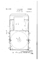
- Figure l is a side View of a fire hose truck embodying my invention.
- Figure 2 is a sectional View taken substantially on line 2 2 of Figure 1, on an enlarged scale,
- Figure 3 is a sectional View taken substantially on line 3-3 of Figure 2, parts being broken away and shown in section and certain parts being shown in elevation;
- Figure 4 is a fragmentary sectional View taken substantially on line 4 4 of Figure 2;
- Figure 5 is a fragmentary detail View, partly in section, of the rim of one of the reels and associated hose attaching means
- Figure 6 is a fragmentary detail view, on an enlarged scale, of a spoke of one of the reels and the associated means for confining the hose in Vwound condition upon the reel, the hose being shown in section;
- Figure 7 is a sectional View taken substantially on line I-Jl of Figure 6;
- Figure 8 is a sectional view, on an enlarged scale, taken substantially on line 8-8 of Figure 2; certain parts being shown in elevation and a portion of the wound hose on the top reel being shown in section;
- Figure 9 is a sectional view, on anlenlarged scale and partly broken away, taken substantially on line 9-9 of Figure 3;
- Figure 10 is a sectional view, on an enlarged scale, taken substantially on iine lll-I9 of Figure 8;
- Figure 1i is a sectional View, on an enlarged scale, taken substantially on line I l--I I of Figure 2, certain parts being shown in elevation, with parts broken away and other parts omitted;
- Figure 12 is a fragmentary side View, on an enlarged scale, of the truck body, this view being taken substantially on line I2-I2 of Figure 2; 5
- Figure 13 is a fragmentary detail view, partly in section, showing the hose guide means in oper-l ative 'position projecting outward beyond the side of the body of the truck;
- Figure 14 is a sectional view, taken substanl0 tially on line Iii-I4 of Figure 1, on an enlarged scale.
- Thebody of the truck comprises a hose compartment I5 having top and bottom decks 20 IE and I'I, respectively, and a rear compartment I8 having a bottom deck I9 disposed above deck I'I.
- Compartment I8 is provided with seats 20 along each side thereof, for the hosemen or firemen, and communicates with hose compartment 25 I5 through an appropriate opening 2 I.
- a vertical standard 22 is mounted in compartment I5 centrally thereof, the upper end portion of this standard being reduced and seated in a boss 23 of a bearing disc 24 overlying and suitably 30 secured to top deck I6.
- the lower end of standard 22 is reduced to provide a stud 25 which eX- tends into a seat plate 26 suitably secured to the upper face of bottom deck I'I and overlying a cross member 2l, in the form of an I beam, of the truck 35 frame.
- a plurality of hose reels 29 are mounted on standard 22 for rotation thereabout. Four reels have been shown, but any desired number of reels may be provided, as will be understood.
- Each of the reels 28 comprisesa central hub 29, 40
- Hub 29 of each reel may be of Cup shape, as shown, and 45 the adjacent ends of the hubs of adjacent reels may receive ball bearing structures 34 of known type which facilitate relative rotation of the reels.
- the lower end of hub 29 of the bottom reel seats upon the top plate of a roller bearing structure 50 36, of known type, bottom plate 31 of which seats upon plate 2E. It will be understood that no ball bearing structure is provided in the upper end of the hub of the top reel, since that is unnecessary.
- the reels are thus mountedin superposed relation 55 for independent rotation about a common vertical axis.
- Rim 32 of each reel comprises an upper bead element 4I) and a flange 4I depending therefrom, the outer circumferential surface of the rim defining a groove of approximately semi-circular cross section in which is mounted a tire 42 of circular cross section, this tire being formed of friction material, conveniently being of solid rubber. This provides means for driving the reel in winding direction, as will be more fully explained presently.
- a resilient flexible strip of metal 43 has its inner end portion extended about and suitably secured to the upper portion of hub 29 of each of the reels 28.
- a hose clip 44 appropriately formed for fitting about the end portion of the hose length adjacent the associated coupling member, is suitably secured to the outer end of strip 43, as by riveting, said clip opening outward as shown in Figure 5.
- the upper arm of clip 44 is provided with an upwardly projecting element 45 disposed to contact the ange 4I of rim 40 of the next superadjacent reel. 28, thus preventing movement of the free end of strip 43 outward beyond the rim of its associated reel.
- Member 46 is disposed in contact with the wound hose h, adjacent the free end thereof, which end is provided with a coupling member, as is known. This provides simple and efficient means for maintaining the hose Wound upon the reel, though it will be understood that any other suitable means may be employed for that purpose.
- the two upper reels 28 are disposed above deck I9 of compartment I8 so that hose thereon may be withdrawn therefrom through opening 2
- the hose compartment I is further provided, at the mid portion of each side thereof, with an opening normally closed by a hingedly mounted door 48 hinged at its forward edge and normally secured closedv by means of a latch 49, adjacent its rearward edge, and a cooperating member 50 secured to the inner face of the side wall of compartment I5.
- the doors 48 are approximately equal in height to the height of compartment I5 and the door openings provide, when the doors are in open position, for winding hose onto or off of any of the reels through the sides of compartment I5.
- the hose lines may be Wound onto or off of the reels with exceptional speed, when required.
- all of the hose lines may be handled through the side openings of the hose compartment, when desired or conditions permit, but the ability to deliver two of the hose lines from the back of the truck is advantageous as conducive to speed in laying the hose lines, when speed is imperative.
- an angle ring 5I is secured to the underface of the top deck I6 of hose compartment I5, this ring having a depending annular flange disposed for coacting with element 45 of clip 44 secured to the free end of strip 43 associated with the top reel, for confining the free end of strip 43 against movement outward beyond the rim of the top reel, in the same manner as the free ends of the strips 43 of the other reels 4are confined against outward movement by depending ilanges 4I of rim 32 of such other reels.
- suitably disposed standards 52, 53, and 54, of step formation are mounted adjacent the reels, in bearing plates 55 and 56 secured to the top and bottom deck I6 and I1, respectively, of hose compartment I5.
- Each of these standards has ric-unted thereon, for rotation thereabout, elongated rollers 51, 58, 59, 60, and 6I, with intervening disks 62 of appreciably greater diameter than the rollers, the bottom rollers 6I functioning as a spacer.
- the remaining rollers are aligned with the respective reels and the disks 62 extend beneath flanges 4I of the reel rim 32, as in Figure 3, eifective for supporting the latter and preventing objectionable sway of the reels.
- I provide means for guiding the hose lines during winding thereof onto or off of l the reels, through side openings of the hose compartment.
- Upper and lower brackets 53 and 64 are secured to the inner face of each side wall of compartment l5, adjacent the top and bottom thereof, respectively, and adjacent the rear of the side door opening.
- An elongated sleeve 65 is mounted for turning movement about the axis of a pintle rod 65 mounted in brackets B3 and 64.
- An upper arm 61 is suitably secured, conveniently by welding, to the upper end of sleeve G5, this arm comprising an inner element Sla and an outer element 675 disposed at an obtuse angle to the inner element. Arm 6'!
- a lower arm I2 shaped conformably to arm 6l is secured to the lower end of sleeve 65 and has associated therewith the tension spring T3 connecting arm 12 to wall member II in the same manner as tension spring 69 connects arm 6T to said wall member.
- a rod I4 is carried by arms 61 and I2 at the forward ends thereof, and supports guide members 15 mounted upon rod 14 for relative rotation.
- Each of the guide members 'I5 flares downward forming a base 1S of materially greater diameter than the body of the guide member and connected thereto by a regular curve merging into the base and the body.
- the guide members 'i5 are disposed in substantial alignment with the respective reels so that hose lines being wound onto or off the reels may be passed about ing the hose line.
- a hose line is un- Wound from one of the reels, it is passed about the corresponding guide member l5, during the unwinding operation, the reel then being rotated counterclockwise, as viewed in Figure 2, the rollers upon Standard 54 assisting also in guid- If the hose line is being wound onto the reel, the latter is rotated clockwise, as viewed in Figure 2, the hose line passing across the corresponding guide member l5 and being guided, in part, by the rollers on the standard 54 or 53, as the case may be.
- a vertically disposed shaft 30 is rotatably mounted in decks
- Shaft is disposed adjacent the reels and has mounted thereon a plurality of bracket structures corresponding in number to the reels.
- Each bracket structure comprises a lower arm 83 having, at its forward end, a flanged bearing member 84 loose upon shaft 00 for turning movement about the latter.
- the bracket structure further includes two upper arms 85 and 85 disposed in spaced parallel relation and mounted upon the ends of a spacing member 0'!
- a stub shaft 88 passes through arms 85 and 86, with its upper end secured in arm 05, bridging the space between arms 06 and 33, and having its lower end secured in the latter arm.
- a spur pinion 00 is rotatably mounted upon stub shaft 88, at the upper face of arm S3, and meshes with a spur gear 00 splined upon shaft 30 for rotation therewith.
- a grooved wheel 02, rigid with pinion 80, conveniently lformed integrally therewith, is disposed for engagement with tire i2 of an adjacent hose reel.
- each of the bracket assemblies comprises a bracket structure swingable in either direction about the axis of shaft 80, this structure carrying a grooved friction wheel driven from shaft ⁇ 30, adapted for cooperation with a tire of a hose reed for rotating the latter. Since the bracket assemblies are similar, the description of one thereof will suffice.
- Shaft 80 may be rotated in desired direction in any suitable manner.
- a bevel gear 94 is secured upon the lower end of shaft 80 and meshes with a bevel gear 05 secured upon a shaft 96.
- the latter shaft may be rotated in any suitable manner but, preferably, is driven from the engine of the truck through the medium of a power take-off of known type. Since power take-offs of this type are known in the art, it is not deemed necessary to illustrate or describe the latter in detail. Suffice it to say that shaft 96 may be driven by power derived from the engine of the truck, in a suitable known manner.
- Arms 85 and 86 of the respective bracket assemblies are extended forward and connected, at their forward ends, by a block 91 secured therebetween.
- the block 01 is bored for reception of a rod 08, provided at its inner end with a rounded head 99 seating in a corresponding socket in the end of the block 91.
- 00 is swiveled to the outer end of rod 98 and is connected, by a tension spring
- 03 is provided with two pairs of studs
- 04 and the associated wall of compartment l5 are provided with aligned openings
- 04 is further provided with projections
- 09 is anchored at one end to wall
- 00 is of light weight, relative to spring I0 I, and acts, when the pull rod
- the bracket assembly By pulling one of the rods 03 into its outer position and securing it there, as shown at the top of Figure 11, the bracket assembly is turned clockwise, as viewed in Figure 2, moving the grooved roller 92 into tight contact with tire 42 of the associated hose reel and yieldingly holding it in such position, thereby establishing driving connection between shaft 80 and the reel.
- the hose reel By rotating shaft 80 in proper direction, the hose reel is turned in winding direction, Winding the hose line thereupon.
- roller 93 contacts the wound hose and is moved outwardly of the reel thereby, thus turning the bracket assembly in oounterclockwise direction, as viewed in Figure 2.
- roller 92 This results first in a certain amount of slippage between roller 92 and tire 42, thus automatically reducing the speed of rotation of the hose reel and, when the latter has become completely lled to proper extent with the wound hose, roller 92 is moved into position effective for completely disabling the drive between this roller and the reel, rotation of the latter then ceasing. This operation will be clear from Figure 8.
- 03a has its inner end connected, by a tension spring H, to a yoke H2 swiveled to the outer end of a link H3 pivoted at its inner end, at H4, to a forked lever H5 pivoted, at H6, on a strip H1 secured to the rearward face of partition H0. 'I'he fork of lever H5 straddles rod 98.
- the hose reels are driven by shaft 00 in hose winding direction only, rotation of the reel in unwinding direction being caused by pulling of the hose therefrom in the laying of the hose line. It will be understood, however, that the reels may be power driven in either direction, if desired.
- individual control means for the hose reel driving mechanism in association with a common shaft for driving such mechanisms, it is possible to drive the hose reels independently of one another or to drive all of the reels simultaneously, to suit conditions. This is advantageous in that it renders possible, where conditions permit, winding of hose lines onto two or more of the reels simultaneously, thus effecting a material saving in time in reeling up the hose lines.
- each hose line comprises a plurality of hose lengths secured together by coupling members in a known manner.
- the reels arerpreferably made of metal, treated and polished so as to avoid accumulation of any appreciable quantity of moisture thereon.
- the wet hose is wound upon the lower reel, or reels, it being understood that the hose lines are unwound from the reels, as required, from the bottom reel up. In this manner, wetting of the dry hose, which has not been removed from the reels, by dripping of water from the wet hose, is avoided.
- the open construction of the hose reels is of advantage in facilitating drying of hose wound thereon and, if desired, the hose compartment may be provided with means for promoting circulation of air therethrough with a view to increasing the rapidity of drying of the hose.
- the wet hose Upon return of the hose truck to a station, the wet hose is removed from the reels and hung up in the hose tower for drying, and is immediately replaced by dry hose wound onto the reels from which the used wet hose has been removed.
- This operation may be performed exceptionally quickly, which is of primary importance in fire extinguishing apparatus.
- the hose lines may be laid from the reels much faster than is possible vvith present-day equipment, which is extremely important. Also, when the hose lines are no longer required, they may be wound onto the reels with expedition and facility, reducing to a minimum the delay in traflic, also an important consideration.
- the means for rotating the reels is preferably power operated, this is not essential, and the shaft may be rotated manually in cases where a power take-01T for driving the shaft is not readily available. It is preferred, however, that shaft 80 be power driven with a view to effecting saving in time in reeling the hose lines, for obvious reasons.
- the upper deck I6 of the hose compartment is disposed a considerable distance below the roof of the truck, as will be clear from Figure l.
- This provides a compartment I8 above the hose compartment, between partitions 'H and deck IG and the roof of the truck, this compartment opening rearward into compartment I8.
- Each side of compartment H8 is closed by two doors H9, hinged at their forward and rearward edges to the truck body. Doors I9 are normally secured closed in a suitable manner, as by means of latches
- Each hose line comprises a plurality of hose lengths, each approximately fty feet long, coupled together end to end in a known manner. It may be desirable under certain conditions, as in extremely cold weather, to uncouple the hose lengths and roll them up individually by hand.
- compartment H8 provides stowage space for the rolled hose lengths.
- This compartment also provides stowage space for other equipment, if desired, readily accessible through either side or the rear of compartment
- the hose reels may be otherwise suitably disposed, within the broader concept of my invention.
- the hose reels are disposed otherwise than as illustrated, they preferably should be arranged to provide a compartment, adjacent the reel compartment, for stowage of rolled up hose lengths and other equipment.
- a body comprising a hose compartment, a plurality of hose reels mounted in said body for independent rotation, said compartment having openings for winding hose onto and off of said reels, hose guide means operatively positionable adjacent said openings, and means for detachably attaching a hose end to the respective reels for winding thereon of the hose, said guide means being disposed, when in its operative position, to guide hose during unwinding thereof from the reel.
- a body comprising a hose compartment, a plurality of superposed hose reels mounted in said body for independent rotation, said compartment having side openings for winding hose onto and off of said reels, doors normally closing said openings, and guide means normally disposed within said compartment automatically movable through said openings into operative position upon opening of said doors, said guide means when in operative position providing hose guide members disposed outward beyond the sides of said body in substantial alignment with the respective reels.
- a body comprising a hose compartment, a. plurality of superposed hose reels mounted in said body for independent rotation, said compartment having openings for winding hose onto and olf of said reels, each of the latter comprising a hub and a rim connected thereto, resilient flexible attaching strips secured at their inner ends to the respective reel hubs and provided at their outer ends with outwardly opening hose clips, the outer ends of said strips being confined against movement outward beyond the rims of said reels, and hose guide means positionable outwardly beyond said body.
- a body comprising a hose compartment, a plurality of coaxial hose reels mounted in said compartment for independent rotation and 'confined against relative radial movement, a driven shaft, and means for selectively driving said reels in hose winding direction from said shaft comprising rotatably mounted members driven from said shaft normally out of driving relation to said reels and movable about said shaft into driving relation to the respective reels.
- a body comprising a hose compartment, a plurality of coaxial superposed hose reels mounted in said compartment for independent rotation and confined against relative radial movement, said compartment having side openings for winding hose onto and off of said reels, a driven shaft, and means controllable from either side of said body for selectively driving said reels in hose winding direction from said shaft comprising rotatably mounted members driven from said shaft and movable thereabout into and out of driving relation to the respective reels.
- a body comprising a hose compartment, a plurality of coaxial hose reels mounted in ⁇ said compartment for independent rotation and confined against relative radial movement, a driven shaft, and means for selectively driving said reels in hose Winding direction.
- said shaft comprising rotatably mounted members driven from said shaft and movable thereabout into and out of driving relation to' the respective reels
- said driving means further comprising a member disposed to contact hose being wound upon the reel and effective for moving said rotatably mounted member out of driving relation to the reel when the latter becomes filled with hose wound thereon.
- a body comprising a hose compartment, a plurality of hose reels mounted in said compartment for rotation about a common vertical axis and confined against relative radial movement, each reel having a rim comprising a friction element, a vertical driven shaft alongside said reels, and means for selectively driving said reels in hose winding direction. from said shaft comprising rotatably mounted members driven from said shaft and movable thereabout into and out of driving contact with said friction elements of the respective reels.
- a body comprising a hose compartment, a plurality of hose reels mounted in said compartment for rotation about a common vertical axis, each reel having a rim comprising a friction element, a vertical driven shaft alongside said reels, a plurality of gears secured on said shaft for rotation therewith, bracket structures associated with the respective gears loose on ⁇ said shaft for independent turning movement thereabout, friction members driven by said gears rotatably mounted in said structures and movable in the movements thereof about said shaft into and out of driving contact with said friction elements, means yieldingly urging said bracket structures in a direction to hold said friction members out of contact with said friction elements, and means for selectively moving said bracket structures into position to dispose said friction members in driving contact with said friction elements.
- a body comprising a hose compartment, a plurality of hose reels mounted in said compartment for rotation about a common vertical axis, each reel having a rim comprising a friction element, a vertical driven shaft alongside said reels, a plurality of gears secured on said shaft for rotation therewith, bracket structures associated with the respective gears loose on said shaft for independent turning movement thereabout, friction members driven by said gears rotatably mounted in said structures and movable in the movements thereof about said shaft into and out of driving contact with said friction elements, means normally holding said bracket structures in position with said friction members out of contact with said friction elements, yielding means for selectively moving said bracket structures into position to dispose said friction members in driving contact with said friction elements, and rollers carried by said bracket structures disposed to contact hose wound upon the respective reels and effective for moving said bracket structures into position to disable the driving contact between said friction members and friction elements, when a reel becomes filled with hose wound thereon.
Description
Dec. 6,1938. c. M. c. BAIRD V FIRE HOSE TRUCK Filed Aug. 5', 1937 IIIILILI.. |||LI C.' M. C, BAIRD FIRE HOSE TRUCK Dec. 6, 1938.
Filed Aug. 5, 1957 6 Sheets- Sheet 2.
C. M. C. BAIRD FIRE osE TRUCK Dec. s, 1938.
6 Sheets-SheefI 3 Filed Aug. 5, 1957 @waal DEC. 6 1938. Q M, C, BAlRlj 2,139,484
FIRE vHOSE TRUCK Filed Aug. 5, 1957 e sheets-'sheet 4 Dec. 6, 1938.
C. M. c". BAIRD FIRE HOSE lTRUCK Filed Aug. 5, 1937` 6 SheetsvSheep 5 WQS Patented Dec. 6, 1938 y UNITED STATES PATENT OFFlCE FIRE HOSE TRUCK Cassius M. Clay Baird, Chicago, Ill.
Application August 5, 1937,`Serial No. 157,495
9 Claims.
This invention relates to re fighting apparatus, and has to do with nre hose trucks and analogous apparatus.
My invention is directed to the provision of a :fire hose truck havingmeansV whereby considerable lengths of hose may be wound onto and olf of reels within the body of the truck, with expedition and facility, effecting a material saving of time in reeling the hose onto the reel and also renderingit possible to wind the ho-se off of the reel for use more quickly than hose can be laid from the ordinary hose trucks, now commonly used. Y
More specifically, it is an object to provide a plurality of hose reels and means for selectively rotating the reels in hose winding direction, or for simultaneously winding the reels n such di rection, optionally. Further objects and advantages will appear from the detailed description.
In the drawings:
Figure l is a side View of a fire hose truck embodying my invention;
Figure 2 is a sectional View taken substantially on line 2 2 of Figure 1, on an enlarged scale,
parts being broken away;
Figure 3 is a sectional View taken substantially on line 3-3 of Figure 2, parts being broken away and shown in section and certain parts being shown in elevation;
Figure 4 is a fragmentary sectional View taken substantially on line 4 4 of Figure 2;
Figure 5 is a fragmentary detail View, partly in section, of the rim of one of the reels and associated hose attaching means;
` Figure 6 is a fragmentary detail view, on an enlarged scale, of a spoke of one of the reels and the associated means for confining the hose in Vwound condition upon the reel, the hose being shown in section; Figure 7 is a sectional View taken substantially on line I-Jl of Figure 6;
Figure 8 is a sectional view, on an enlarged scale, taken substantially on line 8-8 of Figure 2; certain parts being shown in elevation and a portion of the wound hose on the top reel being shown in section;
Figure 9 is a sectional view, on anlenlarged scale and partly broken away, taken substantially on line 9-9 of Figure 3;
Figure 10 is a sectional view, on an enlarged scale, taken substantially on iine lll-I9 of Figure 8;
Figure 1i is a sectional View, on an enlarged scale, taken substantially on line I l--I I of Figure 2, certain parts being shown in elevation, with parts broken away and other parts omitted;
Figure 12 is a fragmentary side View, on an enlarged scale, of the truck body, this view being taken substantially on line I2-I2 of Figure 2; 5
Figure 13 is a fragmentary detail view, partly in section, showing the hose guide means in oper-l ative 'position projecting outward beyond the side of the body of the truck; and
Figure 14 is a sectional view, taken substanl0 tially on line Iii-I4 of Figure 1, on an enlarged scale.
I have illustrated my invention, by way of example, as embodied in an automobile re hose truck T, which, if desired, may have associated l5 therewith a suitable pump driven from the engine of the truck, in which case the apparatus may be considered as a combined re engine and hose truck. Thebody of the truck comprises a hose compartment I5 having top and bottom decks 20 IE and I'I, respectively, and a rear compartment I8 having a bottom deck I9 disposed above deck I'I. Compartment I8 is provided with seats 20 along each side thereof, for the hosemen or firemen, and communicates with hose compartment 25 I5 through an appropriate opening 2 I.
A vertical standard 22 is mounted in compartment I5 centrally thereof, the upper end portion of this standard being reduced and seated in a boss 23 of a bearing disc 24 overlying and suitably 30 secured to top deck I6. The lower end of standard 22 is reduced to provide a stud 25 which eX- tends into a seat plate 26 suitably secured to the upper face of bottom deck I'I and overlying a cross member 2l, in the form of an I beam, of the truck 35 frame. A plurality of hose reels 29 are mounted on standard 22 for rotation thereabout. Four reels have been shown, but any desired number of reels may be provided, as will be understood. Each of the reels 28 comprisesa central hub 29, 40
- inner spokes 39 radiating from hub 29 and connected at their outer ends by an annular reinforcing element 3 I and an outer rim 32 connected to element 3l by outer radial spokes 33. Hub 29 of each reel may be of Cup shape, as shown, and 45 the adjacent ends of the hubs of adjacent reels may receive ball bearing structures 34 of known type which facilitate relative rotation of the reels. The lower end of hub 29 of the bottom reel seats upon the top plate of a roller bearing structure 50 36, of known type, bottom plate 31 of which seats upon plate 2E. It will be understood that no ball bearing structure is provided in the upper end of the hub of the top reel, since that is unnecessary. The reels are thus mountedin superposed relation 55 for independent rotation about a common vertical axis.
A resilient flexible strip of metal 43 has its inner end portion extended about and suitably secured to the upper portion of hub 29 of each of the reels 28. A hose clip 44, appropriately formed for fitting about the end portion of the hose length adjacent the associated coupling member, is suitably secured to the outer end of strip 43, as by riveting, said clip opening outward as shown in Figure 5. The upper arm of clip 44 isprovided with an upwardly projecting element 45 disposed to contact the ange 4I of rim 40 of the next superadjacent reel. 28, thus preventing movement of the free end of strip 43 outward beyond the rim of its associated reel. In winding the hose onto the reel, the end portion of the hose h is inserted into clip 44, as indicated in Figure 5, with the clip disposed adjacent and in advance of coupling member c, of known type, secured upon the end of the hose. Reel 28 is then rotated clockwise, as viewed in Figure 2, first winding strip 43 about hub 29 of the reel and, thereafter, winding the hose tightly upon the reel. After the hose as thus been wound upon the reel it is secured in wound condition thereon in an appropriate manner, I have shown, in Figures 6 and 7, a holding member 46 provided at its lower end with spring clamps 4l of appropriate form and size to fit tightly about one of the reel spokes 33. Member 46 is disposed in contact with the wound hose h, adjacent the free end thereof, which end is provided with a coupling member, as is known. This provides simple and efficient means for maintaining the hose Wound upon the reel, though it will be understood that any other suitable means may be employed for that purpose.
It will be noted from Figure 3, that the two upper reels 28 are disposed above deck I9 of compartment I8 so that hose thereon may be withdrawn therefrom through opening 2|, compartment I8 and the back of the truck. The hose compartment I is further provided, at the mid portion of each side thereof, with an opening normally closed by a hingedly mounted door 48 hinged at its forward edge and normally secured closedv by means of a latch 49, adjacent its rearward edge, and a cooperating member 50 secured to the inner face of the side wall of compartment I5. The doors 48 are approximately equal in height to the height of compartment I5 and the door openings provide, when the doors are in open position, for winding hose onto or off of any of the reels through the sides of compartment I5. By passing two of the lines of hose from the two upper reels through the back of the truck, and passing the lines of hose from the other two reels through the door openings, either one or both, the hose lines may be Wound onto or off of the reels with exceptional speed, when required. Obviously, all of the hose lines may be handled through the side openings of the hose compartment, when desired or conditions permit, but the ability to deliver two of the hose lines from the back of the truck is advantageous as conducive to speed in laying the hose lines, when speed is imperative. With respect to winding the hose onto the top reel, an angle ring 5I is secured to the underface of the top deck I6 of hose compartment I5, this ring having a depending annular flange disposed for coacting with element 45 of clip 44 secured to the free end of strip 43 associated with the top reel, for confining the free end of strip 43 against movement outward beyond the rim of the top reel, in the same manner as the free ends of the strips 43 of the other reels 4are confined against outward movement by depending ilanges 4I of rim 32 of such other reels.
suitably disposed standards 52, 53, and 54, of step formation, are mounted adjacent the reels, in bearing plates 55 and 56 secured to the top and bottom deck I6 and I1, respectively, of hose compartment I5. Each of these standards has ric-unted thereon, for rotation thereabout, elongated rollers 51, 58, 59, 60, and 6I, with intervening disks 62 of appreciably greater diameter than the rollers, the bottom rollers 6I functioning as a spacer. The remaining rollers are aligned with the respective reels and the disks 62 extend beneath flanges 4I of the reel rim 32, as in Figure 3, eifective for supporting the latter and preventing objectionable sway of the reels. It will also be noted, from Figure 3, that the tire 42 on the reel rim contacts the rollers on the standards so that the latter take up radial thrust of the reel. In this manner the reels are effectively supported at the rims thereof and are conned from objectionable swaying or radial movement, while rotation of the reels is not objectionably interfered with, but objectionable spinning thereof is prevented.
Preferably, I provide means for guiding the hose lines during winding thereof onto or off of l the reels, through side openings of the hose compartment. Upper and lower brackets 53 and 64 are secured to the inner face of each side wall of compartment l5, adjacent the top and bottom thereof, respectively, and adjacent the rear of the side door opening. An elongated sleeve 65 is mounted for turning movement about the axis of a pintle rod 65 mounted in brackets B3 and 64. An upper arm 61 is suitably secured, conveniently by welding, to the upper end of sleeve G5, this arm comprising an inner element Sla and an outer element 675 disposed at an obtuse angle to the inner element. Arm 6'! is further provided with a rearwardly projecting iinger 58 to which is attached one end of a tension spring 69, the other end of which is anchored, by means of a bracket T0, to wall 'II between compartments I5 and 20. A lower arm I2 shaped conformably to arm 6l is secured to the lower end of sleeve 65 and has associated therewith the tension spring T3 connecting arm 12 to wall member II in the same manner as tension spring 69 connects arm 6T to said wall member. A rod I4 is carried by arms 61 and I2 at the forward ends thereof, and supports guide members 15 mounted upon rod 14 for relative rotation. Each of the guide members 'I5 flares downward forming a base 1S of materially greater diameter than the body of the guide member and connected thereto by a regular curve merging into the base and the body. The guide members 'i5 are disposed in substantial alignment with the respective reels so that hose lines being wound onto or off the reels may be passed about ing the hose line.
,turning movement about the latter.
these guide members, as will be understood from Figure 3.
When the doors 48 are secured in closed position, the bases of the guide members 15 are in contact with the inner faces of the doors and the guide means is held in the position shown in Figure 2, with the tension springs 69 and 13 under tension. Upon opening of the door 48, the hose guiding means is swung outward, by the action of the tension springs, into the position shown in Figure 13, so as to project outwardly beyond the side wall of the hose compartment. In this position of the guiding means the arms 61 and 12 are in contact with the side wall of the hose compartment, at the rear of the door opening, the guiding means being thus effectively held against further rearward movement. Lines of hose may now be wound onto or off of the reels, each hose line passing about one of the guide members and being guided, in part, by the rollers upon the stepped standards 53 or 54, as the case may be. This operation will be clear from Figures 2 and 13, the guiding means being shown in the latter figure in its projected and operative position. If a hose line is un- Wound from one of the reels, it is passed about the corresponding guide member l5, during the unwinding operation, the reel then being rotated counterclockwise, as viewed in Figure 2, the rollers upon Standard 54 assisting also in guid- If the hose line is being wound onto the reel, the latter is rotated clockwise, as viewed in Figure 2, the hose line passing across the corresponding guide member l5 and being guided, in part, by the rollers on the standard 54 or 53, as the case may be.
In unwinding the hose line from a reel, the end coupling member c is automatically disengaged from clip 44, when the end of the hose line is reached. This occurs due to the fact that the clip 44 opens outward and is confined against movement outward beyond the rim of the reel, and guide roller l5, in its operative position, is disposed outward beyond the side of the hose compartment. This operation will be clear from Figures 2, 5, and 13.
A vertically disposed shaft 30 is rotatably mounted in decks |55 and Il of compartment I5, by means of anti-friction bearings 8| and 02, of known type, and associated parts., Shaft is disposed adjacent the reels and has mounted thereon a plurality of bracket structures corresponding in number to the reels. Each bracket structure comprises a lower arm 83 having, at its forward end, a flanged bearing member 84 loose upon shaft 00 for turning movement about the latter. The bracket structure further includes two upper arms 85 and 85 disposed in spaced parallel relation and mounted upon the ends of a spacing member 0'! loose upon shaft 80 for A stub shaft 88 passes through arms 85 and 86, with its upper end secured in arm 05, bridging the space between arms 06 and 33, and having its lower end secured in the latter arm. A spur pinion 00 is rotatably mounted upon stub shaft 88, at the upper face of arm S3, and meshes with a spur gear 00 splined upon shaft 30 for rotation therewith. A spacing member 0|, loose on shaft 80, extends between the upper end of the spur gear 90 and the lower face of arm 05. A grooved wheel 02, rigid with pinion 80, conveniently lformed integrally therewith, is disposed for engagement with tire i2 of an adjacent hose reel. A. roller 93 is rotatablymounted between the arms 05 and 86, at the rearward ends thereof, and projects rearwardly therebeyond for a purpose to be described presently. It will be seen that each of the bracket assemblies comprises a bracket structure swingable in either direction about the axis of shaft 80, this structure carrying a grooved friction wheel driven from shaft `30, adapted for cooperation with a tire of a hose reed for rotating the latter. Since the bracket assemblies are similar, the description of one thereof will suffice.
Preferably I provide pull rods |03a and associated means for holding them in lengthwise adjustment, at the other side of the hose compartment, these rods and the adjusting means therefor being similar to the rods |03 and associated adjusting means, except that the rods |03@ are of much greater length than the rods |03. Each rod |03a has its inner end connected, by a tension spring H, to a yoke H2 swiveled to the outer end of a link H3 pivoted at its inner end, at H4, to a forked lever H5 pivoted, at H6, on a strip H1 secured to the rearward face of partition H0. 'I'he fork of lever H5 straddles rod 98. When rod |03 is in its withdrawn position, holding the bracket assembly in position for driving the associated hose reel, yoke |00 is disposed outward beyond lever H5. With rod |03 in its inner or retracted position, the bracket assembly is held in inoperative or nonwinding position and yoke |00 is in contact with the fork at the upper end of lever l5. By withdrawing the corresponding rod |03a, the rod 98 may be moved toward the right, as viewed in Figure 11, by means of the forked lever Il", thus turning the bracket assembly into position for driving the corresponding hose reel. In this manner the drive of the hose reels may be controlled from either side of the truck.
Ordinarily, the hose reels are driven by shaft 00 in hose winding direction only, rotation of the reel in unwinding direction being caused by pulling of the hose therefrom in the laying of the hose line. It will be understood, however, that the reels may be power driven in either direction, if desired. By providing individual control means for the hose reel driving mechanism, in association with a common shaft for driving such mechanisms, it is possible to drive the hose reels independently of one another or to drive all of the reels simultaneously, to suit conditions. This is advantageous in that it renders possible, where conditions permit, winding of hose lines onto two or more of the reels simultaneously, thus effecting a material saving in time in reeling up the hose lines.
It is intended that the reels be of sufficient size or capacity to hold hose lines of considerable length, preferably 500 feet or more per reel. Each hose line comprises a plurality of hose lengths secured together by coupling members in a known manner. The reels arerpreferably made of metal, treated and polished so as to avoid accumulation of any appreciable quantity of moisture thereon. In the event hose lines from all of the reels have not been used in fighting a fire, the wet hose is wound upon the lower reel, or reels, it being understood that the hose lines are unwound from the reels, as required, from the bottom reel up. In this manner, wetting of the dry hose, which has not been removed from the reels, by dripping of water from the wet hose, is avoided. The open construction of the hose reels is of advantage in facilitating drying of hose wound thereon and, if desired, the hose compartment may be provided with means for promoting circulation of air therethrough with a view to increasing the rapidity of drying of the hose.
Upon return of the hose truck to a station, the wet hose is removed from the reels and hung up in the hose tower for drying, and is immediately replaced by dry hose wound onto the reels from which the used wet hose has been removed. This operation may be performed exceptionally quickly, which is of primary importance in fire extinguishing apparatus. Likewise, when the truck arrives at the scene of a re, the hose lines may be laid from the reels much faster than is possible vvith present-day equipment, which is extremely important. Also, when the hose lines are no longer required, they may be wound onto the reels with expedition and facility, reducing to a minimum the delay in traflic, also an important consideration.
While the means for rotating the reels, particularly in hose winding direction, is preferably power operated, this is not essential, and the shaft may be rotated manually in cases where a power take-01T for driving the shaft is not readily available. It is preferred, however, that shaft 80 be power driven with a view to effecting saving in time in reeling the hose lines, for obvious reasons.
The upper deck I6 of the hose compartment is disposed a considerable distance below the roof of the truck, as will be clear from Figure l. This provides a compartment I8 above the hose compartment, between partitions 'H and deck IG and the roof of the truck, this compartment opening rearward into compartment I8. Each side of compartment H8 is closed by two doors H9, hinged at their forward and rearward edges to the truck body. Doors I9 are normally secured closed in a suitable manner, as by means of latches |20 engageable with appropriately formed and located uprights |2|, incorporated in the frame work of the truck body. Ready access may thus be had to compartment H8, from the rear or either side thereof.
Each hose line comprises a plurality of hose lengths, each approximately fty feet long, coupled together end to end in a known manner. It may be desirable under certain conditions, as in extremely cold weather, to uncouple the hose lengths and roll them up individually by hand.
When this is done, compartment H8 provides stowage space for the rolled hose lengths. This compartment also provides stowage space for other equipment, if desired, readily accessible through either side or the rear of compartment While I have shown the hose reels as disposedhorizontally, for rotation about a vertical axis, for the reasons above stated, they may be otherwise suitably disposed, within the broader concept of my invention. In the event the hose reels are disposed otherwise than as illustrated, they preferably should be arranged to provide a compartment, adjacent the reel compartment, for stowage of rolled up hose lengths and other equipment.
As above indicated, and as will be understood by those skilled in the art, changes in construction and arrangement of parts of my invention may be resorted to without departing from the 4so i field and scope of the same, and I intend to include all such variations, as fall within the scope of the appended claims, in this application in which the preferred form only of my invention has been disclosed.
I claim:
l. In a hose truck, a body comprising a hose compartment, a plurality of hose reels mounted in said body for independent rotation, said compartment having openings for winding hose onto and off of said reels, hose guide means operatively positionable adjacent said openings, and means for detachably attaching a hose end to the respective reels for winding thereon of the hose, said guide means being disposed, when in its operative position, to guide hose during unwinding thereof from the reel.
2. In a hose truck, a body comprising a hose compartment, a plurality of superposed hose reels mounted in said body for independent rotation, said compartment having side openings for winding hose onto and off of said reels, doors normally closing said openings, and guide means normally disposed within said compartment automatically movable through said openings into operative position upon opening of said doors, said guide means when in operative position providing hose guide members disposed outward beyond the sides of said body in substantial alignment with the respective reels.
3. In a hose truck, a body comprising a hose compartment, a. plurality of superposed hose reels mounted in said body for independent rotation, said compartment having openings for winding hose onto and olf of said reels, each of the latter comprising a hub and a rim connected thereto, resilient flexible attaching strips secured at their inner ends to the respective reel hubs and provided at their outer ends with outwardly opening hose clips, the outer ends of said strips being confined against movement outward beyond the rims of said reels, and hose guide means positionable outwardly beyond said body.
4. In a hose truck, a body comprising a hose compartment, a plurality of coaxial hose reels mounted in said compartment for independent rotation and 'confined against relative radial movement, a driven shaft, and means for selectively driving said reels in hose winding direction from said shaft comprising rotatably mounted members driven from said shaft normally out of driving relation to said reels and movable about said shaft into driving relation to the respective reels.
5. In a hose truck, a body comprising a hose compartment, a plurality of coaxial superposed hose reels mounted in said compartment for independent rotation and confined against relative radial movement, said compartment having side openings for winding hose onto and off of said reels, a driven shaft, and means controllable from either side of said body for selectively driving said reels in hose winding direction from said shaft comprising rotatably mounted members driven from said shaft and movable thereabout into and out of driving relation to the respective reels.
6. In a hose truck, a body comprising a hose compartment, a plurality of coaxial hose reels mounted in` said compartment for independent rotation and confined against relative radial movement, a driven shaft, and means for selectively driving said reels in hose Winding direction. from, said shaft comprising rotatably mounted members driven from said shaft and movable thereabout into and out of driving relation to' the respective reels, said driving means further comprising a member disposed to contact hose being wound upon the reel and effective for moving said rotatably mounted member out of driving relation to the reel when the latter becomes filled with hose wound thereon.
7. In a hose truck, a body comprising a hose compartment, a plurality of hose reels mounted in said compartment for rotation about a common vertical axis and confined against relative radial movement, each reel having a rim comprising a friction element, a vertical driven shaft alongside said reels, and means for selectively driving said reels in hose winding direction. from said shaft comprising rotatably mounted members driven from said shaft and movable thereabout into and out of driving contact with said friction elements of the respective reels.
8. In a hose truck, a body comprising a hose compartment, a plurality of hose reels mounted in said compartment for rotation about a common vertical axis, each reel having a rim comprising a friction element, a vertical driven shaft alongside said reels, a plurality of gears secured on said shaft for rotation therewith, bracket structures associated with the respective gears loose on` said shaft for independent turning movement thereabout, friction members driven by said gears rotatably mounted in said structures and movable in the movements thereof about said shaft into and out of driving contact with said friction elements, means yieldingly urging said bracket structures in a direction to hold said friction members out of contact with said friction elements, and means for selectively moving said bracket structures into position to dispose said friction members in driving contact with said friction elements.
9. In a hose truck, a body comprising a hose compartment, a plurality of hose reels mounted in said compartment for rotation about a common vertical axis, each reel having a rim comprising a friction element, a vertical driven shaft alongside said reels, a plurality of gears secured on said shaft for rotation therewith, bracket structures associated with the respective gears loose on said shaft for independent turning movement thereabout, friction members driven by said gears rotatably mounted in said structures and movable in the movements thereof about said shaft into and out of driving contact with said friction elements, means normally holding said bracket structures in position with said friction members out of contact with said friction elements, yielding means for selectively moving said bracket structures into position to dispose said friction members in driving contact with said friction elements, and rollers carried by said bracket structures disposed to contact hose wound upon the respective reels and effective for moving said bracket structures into position to disable the driving contact between said friction members and friction elements, when a reel becomes filled with hose wound thereon.
CASSIUS M. CLAY BAIRD.
Priority Applications (1)
| Application Number | Priority Date | Filing Date | Title |
|---|---|---|---|
| US157495A US2139484A (en) | 1937-08-05 | 1937-08-05 | Fire hose truck |
Applications Claiming Priority (1)
| Application Number | Priority Date | Filing Date | Title |
|---|---|---|---|
| US157495A US2139484A (en) | 1937-08-05 | 1937-08-05 | Fire hose truck |
Publications (1)
| Publication Number | Publication Date |
|---|---|
| US2139484A true US2139484A (en) | 1938-12-06 |
Family
ID=22563982
Family Applications (1)
| Application Number | Title | Priority Date | Filing Date |
|---|---|---|---|
| US157495A Expired - Lifetime US2139484A (en) | 1937-08-05 | 1937-08-05 | Fire hose truck |
Country Status (1)
| Country | Link |
|---|---|
| US (1) | US2139484A (en) |
Cited By (5)
| Publication number | Priority date | Publication date | Assignee | Title |
|---|---|---|---|---|
| US2621870A (en) * | 1950-01-16 | 1952-12-16 | American Marsh Pumps Inc | Hose reel assembly |
| US2681251A (en) * | 1948-06-12 | 1954-06-15 | Bowser Inc | Liquid dispensing apparatus |
| US5211351A (en) * | 1991-03-28 | 1993-05-18 | Declerck Ronald J | Hose loader |
| US6186166B1 (en) | 1998-08-10 | 2001-02-13 | Myers Quick Drop, Inc. | Fire hose release device |
| US20070177856A1 (en) * | 2006-01-30 | 2007-08-02 | Vince Rottinghaus | Ground heating device |
-
1937
- 1937-08-05 US US157495A patent/US2139484A/en not_active Expired - Lifetime
Cited By (6)
| Publication number | Priority date | Publication date | Assignee | Title |
|---|---|---|---|---|
| US2681251A (en) * | 1948-06-12 | 1954-06-15 | Bowser Inc | Liquid dispensing apparatus |
| US2621870A (en) * | 1950-01-16 | 1952-12-16 | American Marsh Pumps Inc | Hose reel assembly |
| US5211351A (en) * | 1991-03-28 | 1993-05-18 | Declerck Ronald J | Hose loader |
| US6186166B1 (en) | 1998-08-10 | 2001-02-13 | Myers Quick Drop, Inc. | Fire hose release device |
| US20070177856A1 (en) * | 2006-01-30 | 2007-08-02 | Vince Rottinghaus | Ground heating device |
| US7441986B2 (en) * | 2006-01-30 | 2008-10-28 | Vince Rottinghaus | Ground heating device |
Similar Documents
| Publication | Publication Date | Title |
|---|---|---|
| US2558418A (en) | Boat launching and loading trailer | |
| US2139484A (en) | Fire hose truck | |
| US2650730A (en) | Lifting trailer | |
| US4055313A (en) | Apparatus for exchanging rewound rolls in a roll slitting and rewinding machine | |
| US2721709A (en) | Reel stand | |
| US2441791A (en) | Strip feeding mechanism | |
| CN211971388U (en) | Water belt winding device for flood fighting and emergency rescue | |
| US2809496A (en) | Boat trailers | |
| CN211366943U (en) | High-pressure oil pipe rolling disc for locomotive lubricating oil filling device | |
| US2933264A (en) | Hose delivery guide | |
| US1708854A (en) | Means for handling sheet steel | |
| US3716156A (en) | Boat transporter | |
| US3067966A (en) | Cable reel handling apparatus | |
| US3810579A (en) | Automatic sprinkling apparatus | |
| US5097770A (en) | Traveling apparatus for automatically mounting, dismounting, and driving a rail carriage | |
| US2417587A (en) | Clothesline reel | |
| US1925580A (en) | Wind-up mechanism | |
| US4542861A (en) | Reel drive mechanism | |
| US2563377A (en) | Wire handling apparatus | |
| US3581406A (en) | Device for taking off strands wound up on a reeling machine and subsequently dampening in a dampening machine | |
| CN215794093U (en) | Semitrailer carriage | |
| US2202204A (en) | Reel | |
| KR102187531B1 (en) | Winding Apparatus of water removing for fire fighting hose | |
| US2493590A (en) | Apparatus for positioning cores | |
| US2089717A (en) | Tipple truck platform |