US2150776A - Traffic analyzer - Google Patents
Traffic analyzer Download PDFInfo
- Publication number
- US2150776A US2150776A US11086A US1108635A US2150776A US 2150776 A US2150776 A US 2150776A US 11086 A US11086 A US 11086A US 1108635 A US1108635 A US 1108635A US 2150776 A US2150776 A US 2150776A
- Authority
- US
- United States
- Prior art keywords
- condenser
- current
- vehicle
- counter
- winding
- Prior art date
- Legal status (The legal status is an assumption and is not a legal conclusion. Google has not performed a legal analysis and makes no representation as to the accuracy of the status listed.)
- Expired - Lifetime
Links
Images


Classifications
-
- G—PHYSICS
- G08—SIGNALLING
- G08G—TRAFFIC CONTROL SYSTEMS
- G08G1/00—Traffic control systems for road vehicles
- G08G1/01—Detecting movement of traffic to be counted or controlled
- G08G1/0104—Measuring and analyzing of parameters relative to traffic conditions
Definitions
- My invention relates to speed indicating, counting, and analyzing methods and devices and concerns particularly arrangements for analyzing or classifying vehicular traflic.
- the primary object of my invention is to provide simple and ruggedapparatus which may be constructed and operated easily and with relatively little cost for producing both an indication of the speed of a vehicle passing a given point m on the road and a record of the vehicles which have passed, classified according to their speeds. Another object is to provide warnings in case of vehicles passing at'excessive speeds.
- Fig. 1 is a circuit diagram representing one embodiment of my invention
- Fig. 21 s a circuit diagram representing in part another embodiment of my in- 25 vention
- Fig. 3 is a circuit diagram representing in part an embodiment including the feature of producing signals when vehicles pass at excessive speeds
- Fig. 4 is a graph explaining the operation of the arrangement of Fig. 3
- Fig. 5 is 30
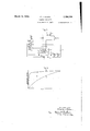
- Fig. 6 is a graph explaining the manner of obtaining readings from the arrangement of Fig. 1.
- Like reference characters are utilized in the drawing 35 to designate like parts throughout.
- I provide a condenser II, a source of current l2, and means l3 for causing the condenser to be connected to 40 the current source 12 when a vehicle reaches a predetermined point in the roadway and for causing the condenser to bedischarged when the vehicle reaches a more advanced predetermined point in the roadway.
- I also provide means, such 45 as an ammeter l4, for determining the quantity of charge collected by thecondenser ll.
- My apparatus is well adapted to the analysis of trafiic consisting of the ordinary road vehicles, 55 primarily automobiles, and for the sake of illustration the invention will be described with reference to such traveling objects. It will be un-' derstood, however, that my invention is not limited thereto and that it may be used for counting moving objects of any character whatever, 5 such as persons, runners in sport contests, airplanes, boats, projectiles, etc.
- any suitable means may be employed for caus ing the passage of the vehicle to eflect the charging and discharging of the condenser II.
- I may provide a pair of circuit-closing devices at two points in the roadway which are operated in succession as the vehicle passes from one point to the next to initiate the charging and discharging of the condenser ll through suit- 15 able relays.
- Each circuit-closing device may take any suitable form, such as a photo-electric tube amplifier and relay actuated upon the interruption of alight beam by the vehicle as it passes,
- treadle switches l5 and iii are located a fixed and determinable distance apart, preferably greater than the length of the ordinary vehicle and less than the length. of two ordinary vehicles. Obviously, if the treadle switches are too far apart, more than one vehicle traveling close together might come between the switches at one time and be counted as one. On the other hand. if the switches are too close together, the axles of each vehicle would be counted separately.
- treadle switches l5 and [6 are so placed with respect to the direction of the vehicles that the treadle I5 is the one first operated.
- a current source H, a resistor l8, and a relayactuating winding l9 are connected in series to the circuit closer l5 and a relay-actuating winding 20 is connected in series with the current source I] to circuit closer IS.
- the relay-actuating winding I9 is provided with and controls a pair of normally open contacts 2
- the relay winding 20 is provided with and controls a pair of normally open contacts 22 which are connected in parallel with the relay winding I!
- the relay I9 is provided with and controls also a pair of stationary contacts 23 and 24 and a movable contact 25 which are so arranged that contacts 24 and 25 are new mally in engagement.
- I For the purpose of registering the-number of vehicles passing on the roadway in addition to providing an indication of the speed of the ve hicles as they pass, I also provide one or more counters 26 to 3!, having actuating or control-- ling windings 32 to 3'! connected in series with the indicating instrument I4.
- the counter-controlling windings may be arranged to operate the counting mechanisms of the counters lit to 3
- counter-controlling winding in the specification and claims, I mean to include both windings actuating the counters directly as in Fig. 5, and those actuating the counters indirectly as in Fig. 1.
- contacts 42 to Ill controlled by windings 32 to 31 are provided for connecting the current source 4
- the current source i2 and the condenser ii are connected in series between the stationary contact 23 and the movable contact 525.
- the counten-controlling windings E2 to fill and the indi cating instrument I 4 are connected in series to the stationary contact 24 of the relay Ill and to the common terminal 38 of the condenser ll hand the current source I2.
- a resistor MI is connected in series with the current source it, having such a resistance with respect to the capacity of the condenser and voltage oi source It as to fix the charging rate of the condenser ii at a suitable value.
- the voltmeter to connected. across thesource I2 may also be employed for checking its voltage.
- the counter-controlling windings 33?. to ill are so designed that each one will operate to close its contacts upon the passage oi as different minimum current.
- the instrument I4 indicates the discharge current or current impulse which depends upon the charge collected by the condenser II, depending in turn upon the time interval between the operating of circuit closers I5 and 16 by the vehicle.
- the instrument I 4 may, therefore, be calibrated in terms of the average speed of the vehicle in its passage from the circuit closer I5 to the circuit closer It.
- each of the counters 26 to 3! is actuated so as to register the passage of the vehicle. If the speed of the vehicle was so great that sufficient charge could be collected to operate only the counter having most sensitive winding and mech anism to operate it, then, of course, only that one counter will register the passage of the ve hicle. In a similar manner, at intermediate speeds a greater or less number of counters will register the passage of the vehicle, depending on its speed. In this way, each counter registers the total number of vehicles which have passed at or below a predetermined speed, each counter being adjusted for a different predetermined vehicle speed limit.
- the register readings indicate that 43?. vehicles have passed at speeds between sixtydlve and ninety miles per hour, 1131 at speeds between fifty and sirtydive miles per hour, M9 at speeds hetween forty and nity miles per hour, 303]. at speeds between thirty and forty miles per hour, 1741 at speeds between twenty and thirty miles per hour, and 753 at speeds under twenty miles per hour.
- the apparatus may be arranged to give an alarm, operate a. warning light, or produce some other signal whenever a vehicle passes at a speed exceeding a predetermined value.
- an additional condenser 5'! is provided.
- a separate current source 58 is also provided.
- the charging and discharging of the condenser 51 are controlled by a pair of stationary contacts 59 and 60 and a movable contact BI operated by the relay winding H in a manner similar to the contacts 23, 24, and 25, which control the charging and discharging of the condenser II.
- One or more suitable current-responsive devices are connected in the discharge circuits of both condensers 51 and I I in such a manner that the discharges of the two condensers pass in the opposite directions through the current-responsive devices.
- I may employ an indicating instrument such as an ammeter 6i! and a relay 63 connected in series with the discharge circuit of the condenser II and also forming a part of the discharge circuit of the condenser 51.
- the ammeter 62 will attain a predetermined deflection only when a vehicle passes at an excessive speed.
- the relay 63 may be provided with contacts 64 and a suitable device, such as a warning light 65, may be connected in series with the auxiliary source I and the contacts 54.
- I may also connect a counter 66 in series with a source 4
- the relay 63 is of such character that it responds only when the current therein exceeds a predetermined value.
- the indicator 62 and the relay 63 respond to passage of vehicles traveling at speeds in excess of a predetermined value instead of below a predetermined value, which will become apparent from a consideration of Fig. 4.
- Fig. 4 is a graph including a curve 5! representing the variation in the voltage of the condenser 51 with time as the condenser 51 is being charged from the source 58 and a curve ll representing the variation in the voltage of the condenser II with time as the condenser II is being charged from the source i2. lit will be observed that I have not shown any resistor in series with the source 58 for charging the condenser 57.
- I may either actually omit the resistor or utilize a resistor of smaller value, relative to the other elements of the circuit, than the resistor 39 so that the charging circuit of the condenser 51 has a considerably shorter time constant than that of the condenser it.
- Fig. 4 the curve 51 rises much more rapidly than the curve 6 [1 before it begins to taper off and approach the horizontal.
- an alarm may be operated whenever a vehicle travels at a speed too low forrproper movement of traffic.
- a warning bell 61 or other suitable device may be connected in shunt with the counting register 21, which was arbitrarily assumed to count vehicles traveling at thirty miles an hour or less. Accordingly, the warning bell 51 will be rung whenever a passing vehicle holds up tramc by traveling at a speed less than thirty miles an hour.
- a low-speed alarm may also be arranged to operate independently of any of the counter-controlling windings.
- I may provide an undercurrent relay having a winding 68 connected in series with the battery l2 in the charging circuit of the condenser H and having -a-pair of contacts 69 which are normally closed but open when current of suiilcient value flows through the winding 68.
- the relay-actuating winding I9 is provided with an additional pair of normally open contacts I and an auxilliary source of current H is also provided.
- a warning bell 61', or other suitable type of alarm is connected in series with the current source H and the contacts 69 and 10.
- the contacts 10 When no vehicles are passing, the contacts 10 will be open and no current, of course, will flow through the warning bell 61. However, when the circuit closer I5 is operated by the passage of a vehicle and the relay winding I9 is actuated, the contacts 10 will close and simultaneously the contacts 23 and 25 will close, causing the condenser charging current to flow through the wind ing 68 of the undercurrent relay. In consequence, the contacts 69 will open, preventing the flow of current through the Warning bell 61'.
- the undercurrent relay 68 is so designed that, when a vehicle travels at a speed which is below a predetermined value, the value to which the current in the winding 68 falls will be insufilcient to maintain the contacts 69 in the open position. According, the contacts 69 will close and cause the warning bell 5'! to be energized. When a'vehicle reaches the circuit closer l6 and deenergizes the relay winding iii, the contacts it will reopen and the underspeed warning circuit will be restored to its original position.
- the registers 25 to M are made to correspond to different top speeds by employing register-actuating windings 32 to 31 having different sensitivities.
- the range of speed limits represented by the different counters may be increased by varying also the charac teristics of other elements of the circuit, causing variations in the length of the condenser-charg ing period required to cause the actuation of a register.
- I employ a plurality of condenser circuits, each of which may include one or more registercontrolling windings as illustrated in Fig. 1. For the sake of clearness, I have shown only one register corresponding to each condenser.
- I provide one or more condensers, such as the condenser t9.
- I Associated with the condenser 49, I provided a counting register-controlling winding 50, a relay contact 52, and a register 5! similar to the corresponding apparatus illustrated in Fig. 1.
- the apparatus ill for controlling the charging and discharging of the condensers in response to the passage of vehicles may be similar to that shown in Fig. 1 except that I provide the relay-actuating winding 19 with additional stationary contacts 53 and 54 and an additional movable contact 55 similar to the contacts 23, 24 and 25, respectively.
- the contacts 53 and 55 control the charging of the condenser 49 from a source l2 through a resistor 56 and the contacts 54 and 55 control the discharging of the condenser 49 through the counter-actuating winding 50.
- may be made to differ from the counter 26 in the length of the charging time required to produce an impulse of suflicient strength to operate it and, consequently, in the speed limit of the vehicles which will be counted by it by changing the constants of several elements in the circuit.
- the relay-actuating winding 50 or the rela control spring may be so designed as to operate with a current impulse of a diflerent strength than the winding 82.
- the capacity of the condenser 49 may be made different from that of the condenser ii in order to cause a difierent amount of charge to be collected by the condenser 49 or the resistance of the resistor 55 may be made different from that of the resistor 39 in order to change the time required for a predetermined charge to be collected by the condenser 49.
- a device for analyzing vehicle traflic according to traveling speeds comprising in combination, a two-position relay biased to a normal position having normally closed and normally open contacts, means for energizing said relay when a vehicle crosses a given point and means for deenergizing the relay when the vehicles crosses a second moreadvanced point, a
- condenser and a source of current connected in series to the normally open contacts of said relay a plurality of counter-controlling windings responsive to different minimum current values corresponding to different predetermined vehicle speeds, said windings being connected in series with said condenser to the normally closed contacts of said relay, and a plurality of counting registers, one for each of said counter-controlling windings, a separate register being provided for counting the number of vehicles passing at speeds below each predetermined speed.
- a device for analyzing vehicle traflic according to traveling speeds comprising in combination, a condenser, a source of current, a plurality of counter-controlling windings, means for connecting said condenser to said source of current when a vehicle crosses a given point and both disconnecting said source of current and discharging said condenser through said counter controlling windings when the vehicle crosses the second more advanced point, and a plurality of counting registers, one for each of said counter-controlling windings, said countercontrolling windings being responsive to diiferent minimum current values corresponding to different predetermined vehicle speeds, a separate register being provided for counting the number of vehicles passing at speeds below each predetermined speed.
- a device for selectively counting moving objects according to speed comprising in combination, a plurality of condenser discharge circuits, each including a condenser, a counter-controlling winding, a double-throw circuit maker and breaker, and connecting conductors,counting regelectrical dimensions that a dverent charging time is required in each circuit to produce a current impulse of sufllcient strength to operate the counting register corresponding thereto, whereby the registers count the objects passing at speeds below diflerent predetermined values.
- a device for separately counting objects traveling at speeds above and below a predetermined speed comprising in combination, a condenser, a source of current, an upper limit counter-controlling winding responsive to A a predetermined minimum current, a counting register operated thereby, a second condenser, a second source of current, a lower limit countercontrolling winding responsive to a predetermined minimum current, a second counting register operated thereby, means for connecting said condensers to their respectiv sources of current whenever an object crosses a ven point and disconnecting said sources of current whenever the object crosses a second more advanced point, and means for simultaneously discharging the first of said condensers through said upper limit counter-controlling winding and discharging both of said condensers oppositely through said lower limit counter-controlling winding whenever the object crosses the second point.
- a device for counting objects traveling above a predetermined speed on a roadway comprising in combination, a condenser, a source of charging current therefor, a second condenser, a second source of charging current therefor, a a counter-controlling winding responsive to a predetermined minimum current, a counting register operable thereby, means for connecting said condensers to said sources of current whenever an object crosses a given point and disconnecting said sources of current whenever the object crosses a second more advanced point, and means for discharging said condensers oppositely through said counter-controlling winding when the object has crossed the second point.
- Apparatus responsive to the pasage of an object above a predetermined speed comprising in combination, a condenser, a source of charging current therefor, a second condenser, a second source of charging current therefor, a device responsive to a predetermined minimum current, means for connecting said condensers to said sources of current whenever an object crosses a given point and disconnecting said sources of current whenever the object crosses a second more advanced point, and means for discharging said condensers oppositely through said current-responsive device when the object has crossed the second point.
- Apparatus separately responsive to the passage of objects traveling at speeds above and below a predetermined speed comprising in combination, a condenser, a source of current,-an upper speed limit current-responsive device responsive to a predetermined minimum current, a second condenser, a second source of current, a lower speed limit current-responsive device responsive to a predetermined minimum current, means for connecting said condensers to their respective sources of current whenever an object crosses a given point, and means for disconnecting said sources of current and simultaneously discharging the first of said condensers through the upper speed limit current-responsive device and discharging both of said condensers oppositely through said lower speed limit ourrent-responsive device whenever the object crosses a second more advanced point.
- An analyzer for traiflc units passing between two points at various speeds said traflic analyzer comprising a condenser, a plurality of counting devices with controlling windings selectively responsive to difierent magnitudes of condenser discharge current for classifying the number of trafiic units passing between said points according to their speeds and means responsive to the passage of a traffic unit between two given points for charging said condenser during such passage and thereafter discharging said condenser through said windings.
- a tramc analyzer comprising condenser means, current-supply means for charging said condenser means, means for connecting said current-supplymeans to said condenser means during passage of a trafiic unit between two given points, counting means including current-conducting controlling winding means selectively responsive only to current impulses having a magnitude lying on a given side of a predetermined limit, and means for discharging said condenser means through said countercontrolling winding means after passage of a traflic unit.
- a traflic analyzer comprising a condenser, a source of current having a substantially constant voltage, a plurality of counting devices with controlling windings selectively responsive to different magnitudes of condenser discharge cur- FRANK J. MOLES.
Description
March 1'4, 1939. v .F MOL S 2150,776
TRAFFI C ANALYZER Filed March. 14, 1335 5 Sheets-Sheet l Fig.1.
as .27 as 29- Inventor: Frank J. Moles,
y W l i i jAbtorne g.
March 14, 1939. 9 F. J. MOLES 2,150,776
TRAFFIC ANALYZER Filed Marchvl4, 1935 3 Sheets-Sheet 2 CONDENSER VOLTAGE TIME Inventor": Frank J. Moles,
by Hwy 5. flaw-A44 is Attorneg.
Patented Mar. 14, 1939 UNITED STATES PATENT OFFICE" TRAFFIC ANALYZER Frank J. Moles, Ferndale, Mich., assignor to General Electric Company, a corporation of New York My invention relates to speed indicating, counting, and analyzing methods and devices and concerns particularly arrangements for analyzing or classifying vehicular traflic.
The primary object of my invention is to provide simple and ruggedapparatus which may be constructed and operated easily and with relatively little cost for producing both an indication of the speed of a vehicle passing a given point m on the road and a record of the vehicles which have passed, classified according to their speeds. Another object is to provide warnings in case of vehicles passing at'excessive speeds.
Other and further objects and advantages will 15 become apparent as the description proceeds.
The features of my invention which are believed to be novel and patentable will be pointed out in the claims appended hereto. My invention may best be understood by referring to the following description taken in connection with the accompanying drawings in which Fig. 1 is a circuit diagram representing one embodiment of my invention; Fig. 21s a circuit diagram representing in part another embodiment of my in- 25 vention; Fig. 3 is a circuit diagram representing in part an embodiment including the feature of producing signals when vehicles pass at excessive speeds; Fig. 4 is a graph explaining the operation of the arrangement of Fig. 3; Fig. 5 is 30 a circuit diagramv representing in part a modification of the arrangement of Fig. 1; and Fig. 6 is a graph explaining the manner of obtaining readings from the arrangement of Fig. 1. Like reference characters are utilized in the drawing 35 to designate like parts throughout.
In carrying out my invention according to the embodiment illustrated in Fig. 1, I provide a condenser II, a source of current l2, and means l3 for causing the condenser to be connected to 40 the current source 12 when a vehicle reaches a predetermined point in the roadway and for causing the condenser to bedischarged when the vehicle reaches a more advanced predetermined point in the roadway. I also provide means, such 45 as an ammeter l4, for determining the quantity of charge collected by thecondenser ll. Since the time required for a vehicle to pass from one point to another is inversely proportional to its speed, the duration of the charging of the con- 50 denser H and, with the right circuit constants, the amount of charge collected by it will be a function of the speed of the vehicle.
My apparatus is well adapted to the analysis of trafiic consisting of the ordinary road vehicles, 55 primarily automobiles, and for the sake of illustration the invention will be described with reference to such traveling objects. It will be un-' derstood, however, that my invention is not limited thereto and that it may be used for counting moving objects of any character whatever, 5 such as persons, runners in sport contests, airplanes, boats, projectiles, etc.
Any suitable means may be employed for caus ing the passage of the vehicle to eflect the charging and discharging of the condenser II. For example, I may provide a pair of circuit-closing devices at two points in the roadway which are operated in succession as the vehicle passes from one point to the next to initiate the charging and discharging of the condenser ll through suit- 15 able relays. Each circuit-closing device may take any suitable form, such as a photo-electric tube amplifier and relay actuated upon the interruption of alight beam by the vehicle as it passes,
or may simply take, the form of a treadle, such 2 as those represented schematically at l5 and I6 for closing electrical contacts as the vehicle passes over the points in the roadway where the treadles are placed. The treadle switches l5 and iii are located a fixed and determinable distance apart, preferably greater than the length of the ordinary vehicle and less than the length. of two ordinary vehicles. Obviously, if the treadle switches are too far apart, more than one vehicle traveling close together might come between the switches at one time and be counted as one. On the other hand. if the switches are too close together, the axles of each vehicle would be counted separately. This would not do any harm, however, and would merely call for utilizing counters advanced half as fast as in the case of an arrangement which did not count the two axles of a vehicle separately. The treadle switches l5 and [6 are so placed with respect to the direction of the vehicles that the treadle I5 is the one first operated.
A current source H, a resistor l8, and a relayactuating winding l9 are connected in series to the circuit closer l5 and a relay-actuating winding 20 is connected in series with the current source I] to circuit closer IS. The relay-actuating winding I9 is provided with and controls a pair of normally open contacts 2| which are connected in parallel with the circuit closer l5 to maintain a holding circuit through the relay- 5o actuating winding l9 after the vehicle has passed the circuit closer l5 and has permitted it to open. The relay winding 20 is provided with and controls a pair of normally open contacts 22 which are connected in parallel with the relay winding I! for the purpose of short-circuiting the relay winding I9 and permitting its contacts to drop out when the vehicle has reached and operated the circuit closer I6. The relay I9 is provided with and controls also a pair of stationary contacts 23 and 24 and a movable contact 25 which are so arranged that contacts 24 and 25 are new mally in engagement.
For the purpose of registering the-number of vehicles passing on the roadway in addition to providing an indication of the speed of the ve hicles as they pass, I also provide one or more counters 26 to 3!, having actuating or control-- ling windings 32 to 3'! connected in series with the indicating instrument I4. The counter-controlling windings may be arranged to operate the counting mechanisms of the counters lit to 3| directly as illustrated in Fig.5, or indirectly through control of an auxiliary current source M.
By the term counter-controlling winding in the specification and claims, I mean to include both windings actuating the counters directly as in Fig. 5, and those actuating the counters indirectly as in Fig. 1. In the arrangement illustrated in Fig. 1, contacts 42 to Ill controlled by windings 32 to 31 are provided for connecting the current source 4| to the counters 26 to ill, respectively. The current source i2 and the condenser ii are connected in series between the stationary contact 23 and the movable contact 525. The counten-controlling windings E2 to fill and the indi cating instrument I 4 are connected in series to the stationary contact 24 of the relay Ill and to the common terminal 38 of the condenser ll hand the current source I2. Preferably a resistor MI is connected in series with the current source it, having such a resistance with respect to the capacity of the condenser and voltage oi source It as to fix the charging rate of the condenser ii at a suitable value. The voltmeter to connected. across thesource I2 may also be employed for checking its voltage.
The counter-controlling windings 33?. to ill are so designed that each one will operate to close its contacts upon the passage oi as different minimum current.
The operation of the apparatus is as follows:
When the vehicle, traveling in the direction oi thearrow 48, crosses the circuit closer Iii, the relay winding I9 is energized, a holding circuit is completed through the contact 2 I, and the I110V- able contact 25 is moved against the stationary contact 23. The condenser II is thereby connected to the current source I2 and begins to receive a charge. When the vehicle crosses the circuit closer IS, the relay winding 20 is actuated, closing the contact 22 scTas to deenergize the relay l9 and permit its contacts to drop out, bringing the movable contact 25 against the stationary contact 24. This operation disconnects the com denser II from the source I2 and closes a discharging circuit through the instrument I4 and the counter-controlling windings 32 to 31. The instrument I4 indicates the discharge current or current impulse which depends upon the charge collected by the condenser II, depending in turn upon the time interval between the operating of circuit closers I5 and 16 by the vehicle. The instrument I 4 may, therefore, be calibrated in terms of the average speed of the vehicle in its passage from the circuit closer I5 to the circuit closer It.
The passage of the vehicle also causes current to flow through the windings 32 to It! and, the current or the current impulse is of sufficient value, each of the counters 26 to 3! is actuated so as to register the passage of the vehicle. If the speed of the vehicle was so great that sufficient charge could be collected to operate only the counter having most sensitive winding and mech anism to operate it, then, of course, only that one counter will register the passage of the ve hicle. In a similar manner, at intermediate speeds a greater or less number of counters will register the passage of the vehicle, depending on its speed. In this way, each counter registers the total number of vehicles which have passed at or below a predetermined speed, each counter being adjusted for a different predetermined vehicle speed limit. For example, let it he assumed that the counter 26 or its controlling winding is ad iusted to respond to all vehicles traveling at a speed of twenty miles per hour or less, counter ill is adjusted. for vehicles under thirty miles per hour, counter 2B for vehicles under forty m1 per hour, counter Ml for vehicles under fifty miles per hour, counter at ior vehicles under sixty) miles per hour, and counter 3i i or vehicles un ninety miles per hour. ".IThen let it he iurt assumed that the registers of the counters it to ill, inclusive, have reached the readings indicated in lE-ig. 6 of "(53, 2509, 553i, Gilli, Mi li, and 7973. respectively. The reading of each register indi-- cates the number oi. vehicles which has pas i since the register was to zero at a speed the corresponding speed range. For example,
ifor the arbitrary values assumed, the register readings indicate that 43?. vehicles have passed at speeds between sixtydlve and ninety miles per hour, 1131 at speeds between fifty and sirtydive miles per hour, M9 at speeds hetween forty and nity miles per hour, 303]. at speeds between thirty and forty miles per hour, 1741 at speeds between twenty and thirty miles per hour, and 753 at speeds under twenty miles per hour.
While in Fig. i I have shown an arrangement in which the countei controlling windings are connected in series, it will he understood that my invention is not limited to such connection but obviously includes also the use of parallel connected windings, and separate condensers and resistors for each counter actuating winding if desired.
If desired, the apparatus may be arranged to give an alarm, operate a. warning light, or produce some other signal whenever a vehicle passes at a speed exceeding a predetermined value. Such an arrangement is illustrated in part in Fig. 3. Preferably, for this purpose, an additional condenser 5'! is provided. In order to charge the condenser 5i, a separate current source 58 is also provided. The charging and discharging of the condenser 51 are controlled by a pair of stationary contacts 59 and 60 and a movable contact BI operated by the relay winding H in a manner similar to the contacts 23, 24, and 25, which control the charging and discharging of the condenser II.
One or more suitable current-responsive devices are connected in the discharge circuits of both condensers 51 and I I in such a manner that the discharges of the two condensers pass in the opposite directions through the current-responsive devices. For example, I may employ an indicating instrument such as an ammeter 6i! and a relay 63 connected in series with the discharge circuit of the condenser II and also forming a part of the discharge circuit of the condenser 51. The ammeter 62 will attain a predetermined deflection only when a vehicle passes at an excessive speed. The relay 63 may be provided with contacts 64 and a suitable device, such as a warning light 65, may be connected in series with the auxiliary source I and the contacts 54. ll desired, I may also connect a counter 66 in series with a source 4| and the contacts 64 for the purpose of registering the number of vehicles passing at excessive speed.
The relay 63 is of such character that it responds only when the current therein exceeds a predetermined value. The indicator 62 and the relay 63 respond to passage of vehicles traveling at speeds in excess of a predetermined value instead of below a predetermined value, which will become apparent from a consideration of Fig. 4. Fig. 4 is a graph including a curve 5! representing the variation in the voltage of the condenser 51 with time as the condenser 51 is being charged from the source 58 and a curve ll representing the variation in the voltage of the condenser II with time as the condenser II is being charged from the source i2. lit will be observed that I have not shown any resistor in series with the source 58 for charging the condenser 57. In practice, I may either actually omit the resistor or utilize a resistor of smaller value, relative to the other elements of the circuit, than the resistor 39 so that the charging circuit of the condenser 51 has a considerably shorter time constant than that of the condenser it. This is apparent from Fig. 4 in which the curve 51 rises much more rapidly than the curve 6 [1 before it begins to taper off and approach the horizontal.
The difference in voltage between the condensers 5i and i I in any instant while both condensers are being charged through their respective current sources is indicated by the difference in the ordinates of the curves 5i and it. it will be seen that this difference, Er, which is the resultant voltages acting upon the current- responsive devices 62 and 63 progressively decreases as the charging time increases. Therefore, when vehicles pass at low speeds and permit the condensers to be charged through relatively long periods, the
resultant voltage Er, will be relatively small, whereas in the cases oi vehicles passing at high speeds, within the range of the apparatus,'the resultant voltage, Er, will be relatively great. Accordingly, by suitable calibration of the devices b2 and 63, a response may be obtained only whenever a vehicle passes at an excessive speed.
If desired, an alarm may be operated whenever a vehicle travels at a speed too low forrproper movement of traffic. For example, as shown in Fig. l, a warning bell 61 or other suitable device may be connected in shunt with the counting register 21, which was arbitrarily assumed to count vehicles traveling at thirty miles an hour or less. Accordingly, the warning bell 51 will be rung whenever a passing vehicle holds up tramc by traveling at a speed less than thirty miles an hour.
A low-speed alarm may also be arranged to operate independently of any of the counter-controlling windings. For this purpose, I may provide an undercurrent relay having a winding 68 connected in series with the battery l2 in the charging circuit of the condenser H and having -a-pair of contacts 69 which are normally closed but open when current of suiilcient value flows through the winding 68. The relay-actuating winding I9 is provided with an additional pair of normally open contacts I and an auxilliary source of current H is also provided. A warning bell 61', or other suitable type of alarm, is connected in series with the current source H and the contacts 69 and 10.
When no vehicles are passing, the contacts 10 will be open and no current, of course, will flow through the warning bell 61. However, when the circuit closer I5 is operated by the passage of a vehicle and the relay winding I9 is actuated, the contacts 10 will close and simultaneously the contacts 23 and 25 will close, causing the condenser charging current to flow through the wind ing 68 of the undercurrent relay. In consequence, the contacts 69 will open, preventing the flow of current through the Warning bell 61'. However, if the vehicle passes at an undesirably low rate of speed, the charging of the condenser [I will continue for such a length of time that the voltage of the condenser it approaches that of the battery 12 and the charging current will fall below a predetermined value, depending upon the constants of the circuit. The undercurrent relay 68 is so designed that, when a vehicle travels at a speed which is below a predetermined value, the value to which the current in the winding 68 falls will be insufilcient to maintain the contacts 69 in the open position. According, the contacts 69 will close and cause the warning bell 5'! to be energized. When a'vehicle reaches the circuit closer l6 and deenergizes the relay winding iii, the contacts it will reopen and the underspeed warning circuit will be restored to its original position.
In the arrangement of Fig. l, the registers 25 to M are made to correspond to different top speeds by employing register-actuating windings 32 to 31 having different sensitivities. The range of speed limits represented by the different counters may be increased by varying also the charac teristics of other elements of the circuit, causing variations in the length of the condenser-charg ing period required to cause the actuation of a register. For example, in the arrangement of Fig. 2, I employ a plurality of condenser circuits, each of which may include one or more registercontrolling windings as illustrated in Fig. 1. For the sake of clearness, I have shown only one register corresponding to each condenser.
In addition to the condenser ii, I provide one or more condensers, such as the condenser t9.
Associated with the condenser 49, I provided a counting register-controlling winding 50, a relay contact 52, and a register 5! similar to the corresponding apparatus illustrated in Fig. 1. The apparatus ill for controlling the charging and discharging of the condensers in response to the passage of vehicles may be similar to that shown in Fig. 1 except that I provide the relay-actuating winding 19 with additional stationary contacts 53 and 54 and an additional movable contact 55 similar to the contacts 23, 24 and 25, respectively. The contacts 53 and 55 control the charging of the condenser 49 from a source l2 through a resistor 56 and the contacts 54 and 55 control the discharging of the condenser 49 through the counter-actuating winding 50.
The counter 5| may be made to differ from the counter 26 in the length of the charging time required to produce an impulse of suflicient strength to operate it and, consequently, in the speed limit of the vehicles which will be counted by it by changing the constants of several elements in the circuit. As in the arrangement of Fig. 1, the relay-actuating winding 50 or the rela control spring may be so designed as to operate with a current impulse of a diflerent strength than the winding 82. The capacity of the condenser 49 may be made different from that of the condenser ii in order to cause a difierent amount of charge to be collected by the condenser 49 or the resistance of the resistor 55 may be made different from that of the resistor 39 in order to change the time required for a predetermined charge to be collected by the condenser 49.
While I have specifically mentioned definite circuit elements, the constants of which may be varied in order to vary the speed limits to which the register will respond, it will be understood that the resistance, capacity, inductance or other suitable properties of any desired circuit elements may be varied in order to produce the variation in characteristics of the counters.
I have herein shown and particularly described certain embodiments of my invention and certain methods of operation embraced therein for the purpose of explaining its principle and showing its application but it will be obvious to those skilled in the art that many modifications and variations are possible and I aim, therefore, to cover all such modifications andvariations as fall within the scope ot my invention which is defined in the appended claims.
What I claim as new and desire to secure by Letters Patent of the United States is:
1. A device for analyzing vehicle traflic according to traveling speeds, said device comprising in combination, a two-position relay biased to a normal position having normally closed and normally open contacts, means for energizing said relay when a vehicle crosses a given point and means for deenergizing the relay when the vehicles crosses a second moreadvanced point, a
condenser and a source of current connected in series to the normally open contacts of said relay, a plurality of counter-controlling windings responsive to different minimum current values corresponding to different predetermined vehicle speeds, said windings being connected in series with said condenser to the normally closed contacts of said relay, and a plurality of counting registers, one for each of said counter-controlling windings, a separate register being provided for counting the number of vehicles passing at speeds below each predetermined speed.
2. A device for analyzing vehicle traflic according to traveling speeds, said device comprising in combination, a condenser, a source of current, a plurality of counter-controlling windings, means for connecting said condenser to said source of current when a vehicle crosses a given point and both disconnecting said source of current and discharging said condenser through said counter controlling windings when the vehicle crosses the second more advanced point, and a plurality of counting registers, one for each of said counter-controlling windings, said countercontrolling windings being responsive to diiferent minimum current values corresponding to different predetermined vehicle speeds, a separate register being provided for counting the number of vehicles passing at speeds below each predetermined speed.
3. A device for selectively counting moving objects according to speed comprising in combination, a plurality of condenser discharge circuits, each including a condenser, a counter-controlling winding, a double-throw circuit maker and breaker, and connecting conductors,counting regelectrical dimensions that a diilerent charging time is required in each circuit to produce a current impulse of sufllcient strength to operate the counting register corresponding thereto, whereby the registers count the objects passing at speeds below diflerent predetermined values.
4. A device for separately counting objects traveling at speeds above and below a predetermined speed, said device comprising in combination, a condenser, a source of current, an upper limit counter-controlling winding responsive to A a predetermined minimum current, a counting register operated thereby, a second condenser, a second source of current, a lower limit countercontrolling winding responsive to a predetermined minimum current, a second counting register operated thereby, means for connecting said condensers to their respectiv sources of current whenever an object crosses a ven point and disconnecting said sources of current whenever the object crosses a second more advanced point, and means for simultaneously discharging the first of said condensers through said upper limit counter-controlling winding and discharging both of said condensers oppositely through said lower limit counter-controlling winding whenever the object crosses the second point.
5. A device for counting objects traveling above a predetermined speed on a roadway, said device comprising in combination, a condenser, a source of charging current therefor, a second condenser, a second source of charging current therefor, a a counter-controlling winding responsive to a predetermined minimum current, a counting register operable thereby, means for connecting said condensers to said sources of current whenever an object crosses a given point and disconnecting said sources of current whenever the object crosses a second more advanced point, and means for discharging said condensers oppositely through said counter-controlling winding when the object has crossed the second point.
6. Apparatus responsive to the pasage of an object above a predetermined speed, said apparatus comprising in combination, a condenser, a source of charging current therefor, a second condenser, a second source of charging current therefor, a device responsive to a predetermined minimum current, means for connecting said condensers to said sources of current whenever an object crosses a given point and disconnecting said sources of current whenever the object crosses a second more advanced point, and means for discharging said condensers oppositely through said current-responsive device when the object has crossed the second point.
7. Apparatus separately responsive to the passage of objects traveling at speeds above and below a predetermined speed, said apparatus comprising in combination, a condenser, a source of current,-an upper speed limit current-responsive device responsive to a predetermined minimum current, a second condenser, a second source of current, a lower speed limit current-responsive device responsive to a predetermined minimum current, means for connecting said condensers to their respective sources of current whenever an object crosses a given point, and means for disconnecting said sources of current and simultaneously discharging the first of said condensers through the upper speed limit current-responsive device and discharging both of said condensers oppositely through said lower speed limit ourrent-responsive device whenever the object crosses a second more advanced point.
8. An analyzer for traiflc units passing between two points at various speeds, said traflic analyzer comprising a condenser, a plurality of counting devices with controlling windings selectively responsive to difierent magnitudes of condenser discharge current for classifying the number of trafiic units passing between said points according to their speeds and means responsive to the passage of a traffic unit between two given points for charging said condenser during such passage and thereafter discharging said condenser through said windings.
9. A tramc analyzer comprising condenser means, current-supply means for charging said condenser means, means for connecting said current-supplymeans to said condenser means during passage of a trafiic unit between two given points, counting means including current-conducting controlling winding means selectively responsive only to current impulses having a magnitude lying on a given side of a predetermined limit, and means for discharging said condenser means through said countercontrolling winding means after passage of a traflic unit.
10. A traflic analyzer comprising a condenser, a source of current having a substantially constant voltage, a plurality of counting devices with controlling windings selectively responsive to different magnitudes of condenser discharge cur- FRANK J. MOLES.
Priority Applications (1)
| Application Number | Priority Date | Filing Date | Title |
|---|---|---|---|
| US11086A US2150776A (en) | 1935-03-14 | 1935-03-14 | Traffic analyzer |
Applications Claiming Priority (1)
| Application Number | Priority Date | Filing Date | Title |
|---|---|---|---|
| US11086A US2150776A (en) | 1935-03-14 | 1935-03-14 | Traffic analyzer |
Publications (1)
| Publication Number | Publication Date |
|---|---|
| US2150776A true US2150776A (en) | 1939-03-14 |
Family
ID=21748825
Family Applications (1)
| Application Number | Title | Priority Date | Filing Date |
|---|---|---|---|
| US11086A Expired - Lifetime US2150776A (en) | 1935-03-14 | 1935-03-14 | Traffic analyzer |
Country Status (1)
| Country | Link |
|---|---|
| US (1) | US2150776A (en) |
Cited By (19)
| Publication number | Priority date | Publication date | Assignee | Title |
|---|---|---|---|---|
| US2420590A (en) * | 1944-11-29 | 1947-05-13 | Line Material Co | Counting device |
| US2472258A (en) * | 1942-01-09 | 1949-06-07 | Stair | Traffic analyzer |
| US2508965A (en) * | 1943-12-23 | 1950-05-23 | Namenyi-Katz Laszlo | Counting apparatus |
| US2717736A (en) * | 1951-07-17 | 1955-09-13 | Robert A Schlesinger | Exercise counting apparatus |
| DE1063842B (en) * | 1955-03-22 | 1959-08-20 | Trafik & Vaegmaerken A B | Device for traffic monitoring |
| US2934159A (en) * | 1956-02-06 | 1960-04-26 | Butler Oscar | Taxicab control system |
| US3024443A (en) * | 1958-12-02 | 1962-03-06 | Lab For Electronics Inc | Traffic speed monitor |
| US3054087A (en) * | 1958-12-29 | 1962-09-11 | Rue L Clegg | Excessive speed warning system for traffic control |
| DE1159194B (en) * | 1959-07-10 | 1963-12-12 | Walter Herterich | Evaluation device for a method for registering the speed of vehicles |
| DE1160673B (en) * | 1959-01-13 | 1964-01-02 | Siemens Ag | Device for counting vehicles |
| DE1183290B (en) * | 1954-04-14 | 1964-12-10 | Siemens Ag | Arrangement for determining the traffic density of streets and intersections |
| US3195126A (en) * | 1957-05-13 | 1965-07-13 | Lab For Electronics Inc | Traffic supervisory system |
| US3200641A (en) * | 1962-11-23 | 1965-08-17 | Gen Motors Corp | Pinion torque analyzer |
| DE1211827B (en) * | 1962-09-28 | 1966-03-03 | Siemens Ag | Pulse generator for display and / or signal devices in road traffic |
| US3448433A (en) * | 1966-01-18 | 1969-06-03 | Abex Corp | Overspeed and underspeed alarm system |
| FR2204001A1 (en) * | 1972-10-25 | 1974-05-17 | Senac Louis | |
| US4862163A (en) * | 1987-12-30 | 1989-08-29 | Timelapse, Inc. | Traffic monitoring system |
| US20110158331A1 (en) * | 2009-12-31 | 2011-06-30 | Sensys Networks. Inc | Emulating Increased Sample Frequency in a Wireless Sensor Node and/or a Wireless Sensor Network |
| US8855902B2 (en) | 2013-02-28 | 2014-10-07 | Trafficware Group, Inc. | Wireless vehicle detection system and associated methods having enhanced response time |
-
1935
- 1935-03-14 US US11086A patent/US2150776A/en not_active Expired - Lifetime
Cited By (22)
| Publication number | Priority date | Publication date | Assignee | Title |
|---|---|---|---|---|
| US2472258A (en) * | 1942-01-09 | 1949-06-07 | Stair | Traffic analyzer |
| US2508965A (en) * | 1943-12-23 | 1950-05-23 | Namenyi-Katz Laszlo | Counting apparatus |
| US2420590A (en) * | 1944-11-29 | 1947-05-13 | Line Material Co | Counting device |
| US2717736A (en) * | 1951-07-17 | 1955-09-13 | Robert A Schlesinger | Exercise counting apparatus |
| DE1183290B (en) * | 1954-04-14 | 1964-12-10 | Siemens Ag | Arrangement for determining the traffic density of streets and intersections |
| DE1063842B (en) * | 1955-03-22 | 1959-08-20 | Trafik & Vaegmaerken A B | Device for traffic monitoring |
| US2934159A (en) * | 1956-02-06 | 1960-04-26 | Butler Oscar | Taxicab control system |
| US3195126A (en) * | 1957-05-13 | 1965-07-13 | Lab For Electronics Inc | Traffic supervisory system |
| US3024443A (en) * | 1958-12-02 | 1962-03-06 | Lab For Electronics Inc | Traffic speed monitor |
| US3054087A (en) * | 1958-12-29 | 1962-09-11 | Rue L Clegg | Excessive speed warning system for traffic control |
| DE1160673B (en) * | 1959-01-13 | 1964-01-02 | Siemens Ag | Device for counting vehicles |
| DE1159194B (en) * | 1959-07-10 | 1963-12-12 | Walter Herterich | Evaluation device for a method for registering the speed of vehicles |
| DE1211827B (en) * | 1962-09-28 | 1966-03-03 | Siemens Ag | Pulse generator for display and / or signal devices in road traffic |
| US3200641A (en) * | 1962-11-23 | 1965-08-17 | Gen Motors Corp | Pinion torque analyzer |
| US3448433A (en) * | 1966-01-18 | 1969-06-03 | Abex Corp | Overspeed and underspeed alarm system |
| FR2204001A1 (en) * | 1972-10-25 | 1974-05-17 | Senac Louis | |
| US4862163A (en) * | 1987-12-30 | 1989-08-29 | Timelapse, Inc. | Traffic monitoring system |
| US20110158331A1 (en) * | 2009-12-31 | 2011-06-30 | Sensys Networks. Inc | Emulating Increased Sample Frequency in a Wireless Sensor Node and/or a Wireless Sensor Network |
| US8855902B2 (en) | 2013-02-28 | 2014-10-07 | Trafficware Group, Inc. | Wireless vehicle detection system and associated methods having enhanced response time |
| US9020742B2 (en) | 2013-02-28 | 2015-04-28 | Trafficware Group, Inc. | Wireless vehicle detection system and associated methods having enhanced response time |
| US9412270B2 (en) | 2013-02-28 | 2016-08-09 | Trafficware Group, Inc. | Wireless vehicle detection system and associated methods having enhanced response time |
| US9489840B2 (en) | 2013-02-28 | 2016-11-08 | Trafficware Group, Inc. | Wireless vehicle detector aggregator and interface to controller and associated methods |
Similar Documents
| Publication | Publication Date | Title |
|---|---|---|
| US2150776A (en) | Traffic analyzer | |
| US2849701A (en) | Highway condition indicating system | |
| US3593263A (en) | Apparatus for vehicle direction sensing | |
| US2943306A (en) | Object detector | |
| US4760736A (en) | On board indicator for motor vehicles | |
| ES432663A1 (en) | Device for determining, during operation, the category of a vehicle according to a pre-established group of categories | |
| US2999999A (en) | Highway traffic control system | |
| US2701336A (en) | Flaw detector | |
| US2688740A (en) | Range computer | |
| US2477567A (en) | Means for detecting presence and movement of bodies | |
| US2932003A (en) | Electronic cycle computer | |
| US3233234A (en) | Vehicle detector with battery storage element | |
| US3072901A (en) | Doppler frequency speed measuring apparatus | |
| US2459081A (en) | Electrical measuring instrument | |
| US3639894A (en) | Apparatus for detecting traffic information | |
| US2048740A (en) | Light sensitive apparatus | |
| US2558445A (en) | Traffic controlling apparatus | |
| US3024443A (en) | Traffic speed monitor | |
| US2573175A (en) | Electronic signaling system | |
| US2764399A (en) | Motion weighing apparatus | |
| US3477021A (en) | Volume measurement of thread defects by directly integrating signals representing variations in thread thickness | |
| US3335414A (en) | Critical condition warning device | |
| US2329504A (en) | Electric timing device | |
| US2080053A (en) | Car retarder control apparatus and testing means therefor | |
| US1561225A (en) | Method and means for measuring time |