US2540202A - Dynamoelectric machine - Google Patents
Dynamoelectric machine Download PDFInfo
- Publication number
- US2540202A US2540202A US636451A US63645145A US2540202A US 2540202 A US2540202 A US 2540202A US 636451 A US636451 A US 636451A US 63645145 A US63645145 A US 63645145A US 2540202 A US2540202 A US 2540202A
- Authority
- US
- United States
- Prior art keywords
- windings
- winding
- stator
- alternator
- main
- Prior art date
- Legal status (The legal status is an assumption and is not a legal conclusion. Google has not performed a legal analysis and makes no representation as to the accuracy of the status listed.)
- Expired - Lifetime
Links
Images


Classifications
-
- H—ELECTRICITY
- H02—GENERATION; CONVERSION OR DISTRIBUTION OF ELECTRIC POWER
- H02K—DYNAMO-ELECTRIC MACHINES
- H02K19/00—Synchronous motors or generators
- H02K19/16—Synchronous generators
- H02K19/22—Synchronous generators having windings each turn of which co-operates alternately with poles of opposite polarity, e.g. heteropolar generators
- H02K19/24—Synchronous generators having windings each turn of which co-operates alternately with poles of opposite polarity, e.g. heteropolar generators with variable-reluctance soft-iron rotors without winding
Definitions
- the present invention relates to generators and more particularly to control systems and apparatus for the self-excitation of an alternator.
- An object of the invention is to provide an alternator having rotor and stator members and one of the said members having two sections of windings, one section to carry the load required and the other section to provide excitation of the alternator field.
- Another object of the invention is to provide an induction type three phase alternator having two sets of three phase windings.
- One set of the three phase windings is for excitation purposes and the other set of three phase windings for carrying the required load.
- Another object of the invention is to provide an alternator having a stator with a portion thereof made of a permanent magnet steel and a rotor cooperating therewith so as to effect an initial magnetic flux for inducing a current in the field winding of the alternator.
- Another object of the invention is to provide a system in which the output from the exciter stator windings is applied through a three-phase rectifier to the exciting field of the alternator.
- Another object of the invention is to provide a self-excited alternator in which the main output has a three phase step down transformer connected therefrom.
- the secondary of the transformer is connected through a three phase rectifier in parallel with the exciter circuit and to the exciting field of the alternator and the output of the last mentioned rectifier being so regulated as to maintain a predetermined output voltage at the main output lines.
- Another object of the invention is to provide a novel alternator arranged so as to efiect selfexcitation without exciter windings, armature windings, commutator or brushes and with a minimum of moving parts.
- Another object of the invention is to provide a three phase alternator having a main section formed of a ferro-magnetic material, an auxiliary section formed of a permanent magnet, a spacer formed of a non-magnetic material separating the main section from the auxiliary section so as to prevent the leakage of magnetic flux from the auxiliary to the main section and a rotor formed of a ferro-magnetic material having teeth arranged so as to effect a pu sating flow of magnetic flux between opposite poles of the auxiliary section so as to generate a current in three phase windings about the stator and initiate an exciting current for the alternator field winding.
- Another object of the invention is to provide a novel alternator construction having a stator and rotor arranged to effect a three phase inductor type operation.
- the stator has four poles and twelve stator teeth spaced in groups of three, and all teeth of each phase wound with the same polarity and connected in series, together with a field coil placed around each group of three teeth.
- a rotor having ten teeth equally spaced apart for making and breaking magnetic lines of force passing through the respective stator and rotor teeth.
- Another object of the invention is to provide in the latter arrangement series capacitors connected in the three phase output lines of the alternator to counteract the demagnetizing effect 01 an inductive load on the stator winding of the alternator.
- the latter capacitors are so arranged as to introduce a leading current vector which is in phase with the flux or magnetizing vector and out of phase with the demagnetizing current vector resulting from the load so as to counteract the latter demagnetizing efiect of the load on the stator windings of the alternator.
- Another object of the invention is to provide a third form of control system for a self-excited alternator, including a relay operated by the output of the exciter windings so as to close a circuit of a control coil for a carbon pile voltage regulator and connect the exciting field of the alternator to the output of the alternator.
- the relay is arranged so as to open the circuit to the regulator and the exciting field from the output of the alternator at low rotor speeds so as to thereby prevent loss of current from a battery in the output circuit.
- Figure 1 is a longitudinal sectional view of one form of alternator constructed in accordance with the present invention.
- Figure 2 is a longitudinal sectional view of a modified form of alternator embodying the invention.
- Figure 3 is a circuit diagram illustrating the manner of connecting the several windings of the device of Figure 1.
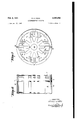
- Figure 4 is an end view of the stator of a modified form of the invention of Figure 1 and illustrating the manner of mounting the several windings.
- Figure 5 is a longitudinal sectional view of the stator of Figure 4 illustrating the several stator windings.
- Figure 6 is a longitudinal sectional view of the. stator of Figure 5 with the stator windings removed.
- Figure 7 is an end view of Figure 6 with the rotor in operating position.
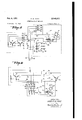
- Figure 8 is a diagrammatic view illustrating a control circuit for the device shown in Figure 3.
- Figure 9 is a diagrammatic view illustrating a control circuit for the device shown in Figure 2.
- Figure 10 is a diagrammatic. view illustratinga modified form of control circuit for the device of Figure 2.
- adynamoelectric machine having an outer casing l in which is mounted a stator including a main section 2', and an auxiliary section 3;
- the main stator section 2 is preferably formed of a series of lamina-tions or punchings made of a' ferro m'agnetic material while the auxiliary stator section 3 is preferably formed of laminations of punchings of" a permanent magnet-steel.
- the main stator section 2 and the auxiliary stator section 3 are separated by a non-magnetic spacer or ring made of a suitable material such as aluminum andindicated by the numeral 4.
- the stator assembly may-be fastened together by cement or other suitable means.
- the purpose of the spacer 11 is to prevent magnetic flux from leaking from the auxiliary permanent magnetic section through the main section.
- the main and auxiliary stator sections as shown in- Figure 3 are formed with four magnetic poles and have twelve stator teeth spaced in groups of three.
- the first tooth in each group is indicated in Figure 3 for example by the numeral 5 on the main section 2' and by numeral 6 onthe auxiliary section 3-;
- the second tooth on the main section 2" is indicated by the numeral T and by numeral 8 on the auxiliary section 3';
- the third tooth is indicated by numeral 9 on the main section 2 and by" numeral It on the auxiliary section 3.
- Main windings H, l2 and [3 are wound about the teeth 5, l and 9, respectively, 50' as toprovide the same polarity and are connected in series.
- exciter windings i6, i5 and it are wound about the teeth 6, 8 and it, respectively, so as to provide the same polarity and are connected in series.
- a field coil l? is wound around each group of teeth of' the main and auxiliary stators 2 and 3, as shown in Figure I.
- the field coils I! are each wound with the same polarity and are connected in series.
- One end of the field winding ll leads to the post i8 while the opposite end is connected to post 29'.
- conductors lead from the exciter windings i4, i5 and Hi to posts 21, i8 and 22, respectively.
- the post l8 serves as a common connector for windi s i2, is and it.
- a rotor 23 mounted within the main and auxiliary stator sections 2 and 3 is a rotor 23 formed preferably of laminations or stampings of ferro-magnetic material and affixed to a drive shaft 25% supported at opposite ends by suitable anti-friction bear- 4 ings, one of which is indicated herein at one end of the shaft 26 by the numeral 25.
- the opposite end of the shaft 2 5 may be driven by an engine or other power means through a suitable constant speed drive which may be of a type such as described and claimed in the U. S. Patent No.
- the rotor 23' is formed with a plurality of teeth illustrated in Figure '7 as ten equally spaced teeth, thirty-six degrees apart and so arranged that upon rotation of the shaft 2d the rotor teeth successively make and break a magnetic circuit through adjoining teeth of the auxiliary stator section and adjoining teeth of the main stator section.
- the purpose of the permanent magnet punchings in the auxiliary stator section is to provide an initial flux for generating a voltage in the exciter windings M, W and I6.
- The: rectifier 23 has output lines 3d and 3E.
- the line til is connected to: post 2? and thereby to one end of the field winding iz'i while the other output.
- line 31 is grounded and connected to the opposite end of the: fieldwinding' it through. the grounded post l8.
- the exciter windings. I l, !5 and. it. provide through the rectifier'28 an initial voltage for the exciting field winding ii.
- the main windings ll and i3 are connected through posts I? and [9 to main output lines 32 and 33,. respectively, while winding i2 is connected through grounded post it to grounded output line 29.
- Conductors 34, 35 and 36' lead from the output lines: 29, 3'2 and 33, respectively, to primary windings 3'? of a step down transformer indicated generally by the numeral 35.
- the transformer 35 has secondary windings 39 which lead to the input of a three phase rectifier it].
- the rectifier 4E3 has output conductors ii and 2.
- the output conductor 4! is grounded and connected to the field winding ii through grounded post.
- the output conductor leads to one end of a variable resistance at which may be of the carbon pile type.
- the opposite end of the variable resistance 23 is connected by a conductor it to the conductor 30 and through post 29 to the field winding ll.
- the output of the rectifier is regulated by a voltage responsive mechanism which controls the variable resistance it so as to maintain a predetermined voltage output on the main lines 29, 32 and 33.
- the latter control mechanism is shown diagrammatically in Figure 8 as including an armature d5 pivoted at .6 and exerting a compressive force upon the carbon pile 43 under tension of a spring ll.
- An electromagnetic winding as is provided for adjusting armature 45 and the spring 41 is arranged so as to balance the magnetic pull on the armature 45 by the electromagnetic winding 48 when the winding 48 is energized by a voltage having a predetermined value.
- the control mechanism is preferably of a type such as shown in the patent application Serial No. 570,602 of William G. Neild filed December 27, 1944, now U. S. Patent No. 2,427,805.
- the electromagnetic winding 48 is connected by conductors 49 and 50 to the output of a rectifier 5! having its input connected through lines 52 and 53 across the main output lines 28 and 32.
- the control coil 48 by varying the resistance of the carbon pile 43 and thereby the excitation of the field winding 1 1 is arranged so as to maintain a substantially constant output voltage in the lines 29, 32 and 33 under varying load condition, since upon increase in load causing a decrease in voltage across the lines 29 and 32 the voltage applied to winding 43 will decrease causing spring 4'? to decrease the resistance of the carbon pile 4'1 and increase the excitation of the field winding II.
- a decrease in load will cause the electromagnetic winding 48 to effect an increase in the resistance of the carbon pile so as to maintain a predetermined voltage output at the lines 23, 32 and 33.
- the latter voltage serves to initially excite the field winding l! which in turn sets up a magnetic field in the main stator teeth 5, l and 9.
- the teeth of the rotor 23 serve to open and close in like manner a magnetic circuit from the latter teeth 5, l and 3 so as to induce a voltage in the main stator windings l i, 52 and i3.
- the transformer 38 rectifier 40 combination of Figure 3 feeds an additional rectified A. C. voltage from the latter main stator windings into the exciting field ii.
- the output voltage from the windings ll, 12 and 13 will then come to a rated value through regulation of the carbon pile 43, as previously described.
- stator laminations or punchings are shown fastened together by rivets 60.
- opposite end plates of the stator assembly have tab members 5! corresponding to each of the stator teeth and arranged to be turned over the stator teeth windings as shown in Figures 4 and 5, so as to better hold the latter windings in position.
- the form of the invention shown in Figures 4, 5, 6 and 7 is otherwise essentially the same as that shown in Figures 1 and 3 as indicated by corresponding numerals.
- FIG. 2 A further modified form of the invention is shown in Figure 2, now the subject matter of Divisional Application Serial No. 165,151, filed May 31, 1950, in which the stator assemblage and rotor construction is essentially the same as previously described with reference to the form of the invention described in Figures '1, 3, 4, 5, 6 and 7 except that the exciter windings I4, I5 and I6 are eliminated and the windings ll, l2 and I3 shown in Figure 3 surround not only the main stator teeth 5, 1 and 9 but also pass about the permanent magnet auxiliary teeth 6, 8 and I 0.
- a spacer 4A formed of a non-magnetic material may be positioned in the space between the permanent magnet auxiliary stator section 3 and the main stator section 2 as shown in Figure 2 to prevent the leakage of magnetic flux from the auxiliary section 3 to the main section 2.
- FIG. 9 A control circuit for the latter form of the invention is shown in Figure 9 in which corresponding numerals indicate corresponding parts to those shown in Figure 8.
- capacitors 14, I5 and 16, respectively Connected in series between the output lines 29, 33 and 32 and input lines 10, H and 72 of an inductance load indicated generally by the numeral 13 are capacitors 14, I5 and 16, respectively.
- the alternating current from the main alternator windings sets up in the inductive load a self induced counter electromotive force which tends to oppose the applied electromotive force of the alternator and the electromagnetic force of the field winding I7 and the permanent magnets 6, 8 and I. so as to tend to demagnetize the alternator.
- the series capacitors '14, 15 and 76 are inserted in the alternator output so as to provide capacitive reactance for counteracting the effects of the inductive reactance on the alternator.
- capacitors l4, l5 and 16 counteract the demagnetizing effect on the alternator of the inductive load which would otherwise tend to cause the alternator to lose its excitation.
- the value of the capacitors selected will assure any desired amount of excitation and if desired may be varied with the inductive load to assure the proper balance between inductive and capacitive reactance.
- Lines 11 and 78 are connected across the input lines It and H of the inductive load 13 and lead to the input of rectifier 5i.
- Output lines 49 and 50 lead from the rectifier 5
- the control coil 48 regulates the carbon pile 43 connected in circuit with the field I! so as to maintain a predetermined output voltage from the alternator across the lines 'Iil-Jl in a manner previously described.
- a third control circuit for the alternator of Figure 2 is shown diagrammatically in Figure 10 and corresponding numerals indicate corresponding parts.
- the alternator output lines 29, 32 and 33 are con- 7 nected to the input of a three Way rectifier 80 having direct current output lines BI and 82 across which may be connected a battery 83 to be charged from the latter supply of direct current.
- Lines 84, 85 and 86 lead from the alternator output lines 29, 32 and 33 to the input of a second three phase rectifier Bl having direct current output lines 88 and 39.
- the line 88 is connected to one end of an electromagnetic winding cc, while the opposite end of the winding 50 is connected by conductor 9! to a relay switch arm 92 controlled by the electromagnetic winding 98.
- the relay switch arm 92 is biased under tension of a spring 93 into a position closing a contact Si l to which there is connected the output line 83 of the rectifier 81.
- a resistor s is connected across the switch 92 and a stop 95 limits the movement of the switch arm 92 in a switch opening direction under force of the electromagnetic winding 96.
- A. second relay switch arm 9? is also controlled by the electromagnetic winding 9t and is biased under tension of a spring 98 in an open circuit position.
- the switch arm 9? is connected through a conductor 99 to the direct current output line 8
- the latter switch arm Bl cooperates with a switch contact Hill and is arranged to close the same under the magnetic force of the electromagnetic winding 9s.
- a conductor it]! leads from the contact we to one end of an electromagnetic winding 52.
- the opposite end of the winding M52 is connected through a conductor it to the output line 32.
- the electromagnetic winding W2 is arranged to regulate a variable resistance carbon pile EM connected at one end by a conductor I65 to the field winding I! and at the opposite end by a conductor N16 to the conductor lei.
- the field winding I1 is connected at the other end to the conductor I03 by a conductor am.
- the resistance of the carbon pile W65 is controlled by an armature Hi8 pivoted at its and exerting a compressive force upon the carbon pile ll l under the tension of a spring H0.
- the electromagnetic winding W2 is arranged to adjust the armature Hi8 against the biasing force of the spring I Iii.
- the spring Mil is arranged so as to balance the pull on armature its by the electromagnetic winding EH2 when the winding I02 is energized by a voltage having a predetermined value.
- the carbon pile regulator is preferably of a type such as shown in the patent application Serial No. 570,002 of William G. Neild filed December 27, 1944; now U. S. Patent No. 2,427,805.
- the control winding I02 maintains the charging voltage of the battery 83 at a predetermined value by controlling the resistance of the carbon pile and thereby the excitation of the field winding I! in response to the charging voltage across the output lines BI and 82.
- the voltage across the lines 88 and 39 decreases to a predetermined low value permitting the switch arm 91 to open contact I and thereby disconnect the control winding W2 and field winding H from the lines 8i and 82 so as to prevent the battery from loss of energy through the field winding l1 and control winding m2.
- An apparatus of the character described comprising, in combination, a stator member, a rotor member, one of said members including a main section and an auxiliary section, the auxiliary section being in the form of a permanent magnet, a main winding about said main section, an exciter winding about said auxiliary section, and a field winding about said main and auxiliary sections, means electrically connecting said exciter and field windings, and said rotor member being so arranged that, upon rotation thereof a voltage may be induced in the exciter winding so as to effect excitation of said field winding.
- the combination comprising a rotor member, a stator member, the stator member including a main section at one end and an auxiliary section at the opposite end, the auxiliary section being in the form of a permanent magnet, a field winding about both sections, a main winding about the main section and having main output lines connected to a load, an exciter winding about the auxiliary section, means electrically connecting the field winding across the exciter winding, and said rotor cooperating with both sections of said stator member so as to cause a pulsating magnetic flux to flow for inducing a voltage in said main and exciter windings and initial excitation of said field winding.
- An induction type alternator comprising two sets of three phase windings, a field winding, a permanent magnet, and a rotor member cooperating therewith so as to induce a voltage in one set of said three phase windings, said other set of three phase windings having output lines for connection to a load, a first three phase unidirectional rectifier electrically connecting said one set of three phase windings to said field winding, a three phase step-down transformer having primary and.
- An induction type alternator comprising, two sets of three phase windings, a field winding, a permanent magnet and a rotor member cooperating therewith so as to induce a voltage in one set of said three phase windings, said other set of three phase windings having output lines for connection to a load, a first three phase unididirectional rectifier electrically connecting said one set of three phase windings to said field winding, a three phase step-down transformer having primary and secondary windings, a second three phase unidirectional rectifier having input and output lines, said primary windings being connected across the output lines of said othe set of three phase windings, said secondary windings being connected to the input lines of said second three phase unidirectional rectifier, and the output lines of said second rectifier being connected to said field winding in parallel to said first rectifier, and means regulating the output of said second rectifier in response to voltage across the output of at least one phase of said other set of three phase windings.
- a dynamo electric machine including a stationary member and a rotatable member, both of said members being formed of a magnetic material, means including a non-magnetic spacer for dividing the stationary member transversely into a pair of substantially separate parallel magnetic' circuits, one of said circuits including a permanent magnet, and the other of said circuits including a field exciting winding arranged for providing a component of excitation to the other of said magnetic circuits, another winding at least in part in said one circuit and electrically connected to said field winding, and said rotatable member arranged in said one circuit so as to effect upon rotation thereof a pulsating magnetic flux from said permanent magnet for causing energization of said other winding and thereby the initial excitation of said field winding.
- An induction type alternator comprising, a stationary member, a non-magnetic spacer for dividing the stationary member transversely into a pair of substantially separate magnetic circuits,
- one of said circuits including a permanent magnet, a rotatable member, said stationary member having a plurality of magnetic poles and a set of three teeth at each pole, windings for said teeth wound with the same polarity and at least in part in said one magnetic circuit, each of said windings connected in series with a winding about a corresponding tooth at other of said poles and in parallel to the windings about other of said teeth, a field coil connected in series with said first mentioned windings and placed around each group of three teeth of said magnetic circuits, and said rotatable member having a plurality of radial teeth equally spaced apart for making and breaking magnetic lines of force passing through the respective stator and rotor teeth.
- a dynamo electric machine comprising, in combination, a stationary member having a main section formed of a ferro-magnetic material and an auxiliary section formed of a permanent magnet having opposite poles, a spacer formed of a non-magnetic material to divide the main and auxiliary sections into a pair of substantially separate parallel magnetic circuits and separating the main section from the auxiliary section so as to prevent the leakage of magnetic flux from the permanent magnet to the main section, a rotatable member formed of a ferro-magnetic material and having teeth arranged so as to effect a pulsating fiow of magnetic flux between opposite poles of the auxiliary section upon rotation of said member, a field winding wound about said main and auxiliary sections, an exciter winding wound at least in part about said auxiliary section, and said pulsating magnetic fiux effecting excitation of said field winding through said exciter winding.
Description
Feb. 6, 1951 H. G. HAAS 2,540,202
DYNAMOELECTRIC MACHINE Filed Dec. 21, 1945 6 sheets sheet 1 NVENTOR- HF/HULD [F.HHHE
W -ATTORNE Feb. 6, 1951 v s 2,540,202
DYNAMOELECTRIC MACHINE Filed Dec. 21, 1945 6 Sheets-Sheet 2 PERMANENT MAGNET wmomss l FlELD 7 wmomcs 7 9 7 MFA/'- 9 5 A.C.WINDINGS 2 a -7 INVENTOR- V ATTORNEY- Feb. 6, 1951 H. e. HAAS 2,540,202
DYNAMOELECTRIC MACHINE Filed Dec. 21, 1945 s Sheets-Sheet s &
l NVENTOR HHHUL D 5. HEW? -ATTORNEY- Feb. 6, 1951 H. G. HAAS 2,540,202
DYNAMOELECTRIC MACHINE Filed Dec. 21, 1945 6 Sheets-Sheet 4 -lNVENTOR- HHHULD 5. HHF75 ATTORNEY Feb. 6, 1951 H. G. HAAS DYNAMOELECTRIC MACHINE 6 Sheets-Sheet 5 Filed Dec. 21, 1945 NVENTOR HHHUL D 5. HfifiiS Feb. 6, 1951 H. G. HAAS 2,540,202
DYNAMOELECTRIC MACHINE Filed Dec. 21, 1945 6 Sheets-Sheet 6 QMWMP a 'INVENTOR ATTORNEY Patented Feb. 6, 1951 UNITED STATES PATENT OFFICE DYNAMOELECTRIO MACHINE Application December 21, 1945, Serial No. 636,451
7 Claims.
The present invention relates to generators and more particularly to control systems and apparatus for the self-excitation of an alternator.
An object of the invention is to provide an alternator having rotor and stator members and one of the said members having two sections of windings, one section to carry the load required and the other section to provide excitation of the alternator field.
Another object of the invention is to provide an induction type three phase alternator having two sets of three phase windings. One set of the three phase windings is for excitation purposes and the other set of three phase windings for carrying the required load.
Another object of the invention is to provide an alternator having a stator with a portion thereof made of a permanent magnet steel and a rotor cooperating therewith so as to effect an initial magnetic flux for inducing a current in the field winding of the alternator.
Another object of the invention is to provide a system in which the output from the exciter stator windings is applied through a three-phase rectifier to the exciting field of the alternator.
Another object of the invention is to provide a self-excited alternator in which the main output has a three phase step down transformer connected therefrom. The secondary of the transformer is connected through a three phase rectifier in parallel with the exciter circuit and to the exciting field of the alternator and the output of the last mentioned rectifier being so regulated as to maintain a predetermined output voltage at the main output lines.
Another object of the invention is to provide a novel alternator arranged so as to efiect selfexcitation without exciter windings, armature windings, commutator or brushes and with a minimum of moving parts.
Another object of the invention is to provide a three phase alternator having a main section formed of a ferro-magnetic material, an auxiliary section formed of a permanent magnet, a spacer formed of a non-magnetic material separating the main section from the auxiliary section so as to prevent the leakage of magnetic flux from the auxiliary to the main section and a rotor formed of a ferro-magnetic material having teeth arranged so as to effect a pu sating flow of magnetic flux between opposite poles of the auxiliary section so as to generate a current in three phase windings about the stator and initiate an exciting current for the alternator field winding.
Another object of the invention is to provide a novel alternator construction having a stator and rotor arranged to effect a three phase inductor type operation. The stator has four poles and twelve stator teeth spaced in groups of three, and all teeth of each phase wound with the same polarity and connected in series, together with a field coil placed around each group of three teeth. There is further provided a rotor having ten teeth equally spaced apart for making and breaking magnetic lines of force passing through the respective stator and rotor teeth.
Another object of the invention is to provide in the latter arrangement series capacitors connected in the three phase output lines of the alternator to counteract the demagnetizing effect 01 an inductive load on the stator winding of the alternator. The latter capacitors are so arranged as to introduce a leading current vector which is in phase with the flux or magnetizing vector and out of phase with the demagnetizing current vector resulting from the load so as to counteract the latter demagnetizing efiect of the load on the stator windings of the alternator.
Another object of the invention is to provide a third form of control system for a self-excited alternator, including a relay operated by the output of the exciter windings so as to close a circuit of a control coil for a carbon pile voltage regulator and connect the exciting field of the alternator to the output of the alternator. The relay is arranged so as to open the circuit to the regulator and the exciting field from the output of the alternator at low rotor speeds so as to thereby prevent loss of current from a battery in the output circuit.
These and other objects and features of the invention are pointed out in the following description in terms of the embodiment thereof which is shown in the accompanying drawings. It is to be understood, however, that the drawings are for the purpose of illustration only, and are not designed as a definition of the limits of the invention, reference being had to the appended claims for this purpose.
In the drawings:
Figure 1 is a longitudinal sectional view of one form of alternator constructed in accordance with the present invention.
Figure 2 is a longitudinal sectional view of a modified form of alternator embodying the invention.
Figure 3 is a circuit diagram illustrating the manner of connecting the several windings of the device of Figure 1.
Figure 4 is an end view of the stator of a modified form of the invention of Figure 1 and illustrating the manner of mounting the several windings.
Figure 5 is a longitudinal sectional view of the stator of Figure 4 illustrating the several stator windings.
Figure 6 is a longitudinal sectional view of the. stator of Figure 5 with the stator windings removed.
Figure 7 is an end view of Figure 6 with the rotor in operating position.
Figure 8 is a diagrammatic view illustrating a control circuit for the device shown in Figure 3.
Figure 9 is a diagrammatic view illustrating a control circuit for the device shown in Figure 2.
Figure 10 is a diagrammatic. view illustratinga modified form of control circuit for the device of Figure 2.
Referring to the form of the invention shown in Figure i, there is depicted adynamoelectric machine having an outer casing l in which is mounted a stator including a main section 2', and an auxiliary section 3;
The main stator section 2 is preferably formed of a series of lamina-tions or punchings made of a' ferro m'agnetic material while the auxiliary stator section 3 is preferably formed of laminations of punchings of" a permanent magnet-steel.
The main stator section 2 and the auxiliary stator section 3 are separated by a non-magnetic spacer or ring made of a suitable material such as aluminum andindicated by the numeral 4. The stator assembly may-be fastened together by cement or other suitable means. The purpose of the spacer 11 is to prevent magnetic flux from leaking from the auxiliary permanent magnetic section through the main section.
The main and auxiliary stator sections as shown in- Figure 3 are formed with four magnetic poles and have twelve stator teeth spaced in groups of three. The first tooth in each group is indicated in Figure 3 for example by the numeral 5 on the main section 2' and by numeral 6 onthe auxiliary section 3-; the second tooth on the main section 2" is indicated by the numeral T and by numeral 8 on the auxiliary section 3'; and the third tooth is indicated by numeral 9 on the main section 2 and by" numeral It on the auxiliary section 3.
Main windings H, l2 and [3 are wound about the teeth 5, l and 9, respectively, 50' as toprovide the same polarity and are connected in series. Similarly exciter windings i6, i5 and it are wound about the teeth 6, 8 and it, respectively, so as to provide the same polarity and are connected in series.
A field coil l? is wound around each group of teeth of' the main and auxiliary stators 2 and 3, as shown in Figure I. The field coils I! are each wound with the same polarity and are connected in series.
Conductors lead from the main windings I I, I2 and E8 toposts I'lA, l8 and f9. One end of the field winding ll leads to the post i8 while the opposite end is connected to post 29'. Similarly, conductors lead from the exciter windings i4, i5 and Hi to posts 21, i8 and 22, respectively. The post l8 serves as a common connector for windi s i2, is and it.
Mounted Within the main and auxiliary stator sections 2 and 3 is a rotor 23 formed preferably of laminations or stampings of ferro-magnetic material and affixed to a drive shaft 25% supported at opposite ends by suitable anti-friction bear- 4 ings, one of which is indicated herein at one end of the shaft 26 by the numeral 25. The opposite end of the shaft 2 5 may be driven by an engine or other power means through a suitable constant speed drive which may be of a type such as described and claimed in the U. S. Patent No.
2,033,835 granted March 10, 1936, in the name of Raymond P. Lansing.
The rotor 23' is formed with a plurality of teeth illustrated in Figure '7 as ten equally spaced teeth, thirty-six degrees apart and so arranged that upon rotation of the shaft 2d the rotor teeth successively make and break a magnetic circuit through adjoining teeth of the auxiliary stator section and adjoining teeth of the main stator section.
The purpose of the permanent magnet punchings in the auxiliary stator section is to provide an initial flux for generating a voltage in the exciter windings M, W and I6.
As shownv in Figure 8. the exciter windings i i and it are connected through conductors 26 and 27 to the. input. of a three phase rectifier 28 while winding i5 is connected through grounded post it and grounded: conductor 29 to the" input of the rectifier 28..
The: rectifier 23 has output lines 3d and 3E. The line til is connected to: post 2? and thereby to one end of the field winding iz'i while the other output. line 31 is grounded and connected to the opposite end of the: fieldwinding' it through. the grounded post l8.
Thus. the exciter windings. I l, !5 and. it. provide through the rectifier'28 an initial voltage for the exciting field winding ii.
The main windings ll and i3 are connected through posts I? and [9 to main output lines 32 and 33,. respectively, while winding i2 is connected through grounded post it to grounded output line 29.
The rectifier 4E3 has output conductors ii and 2. The output conductor 4! is grounded and connected to the field winding ii through grounded post. E8; The output conductor leads to one end of a variable resistance at which may be of the carbon pile type. The opposite end of the variable resistance 23 is connected by a conductor it to the conductor 30 and through post 29 to the field winding ll.
It will be seen then that as soon as the voltage in main windings H, [2 and i3 starts to build up the transformer 33 rectifier l5] combination as shown in Figure 8 feeds rectified A. C. power into the field il in addition to that from the exciter windings l4, I5 and- I6. The output of the rectifier 4i! is connected to the field winding il in parallel to the output of the rectifier 28 supplied by the exciter windings M, i5 and it.
The output of the rectifier is regulated by a voltage responsive mechanism which controls the variable resistance it so as to maintain a predetermined voltage output on the main lines 29, 32 and 33.
The latter control mechanism is shown diagrammatically in Figure 8 as including an armature d5 pivoted at .6 and exerting a compressive force upon the carbon pile 43 under tension of a spring ll. An electromagnetic winding as is provided for adjusting armature 45 and the spring 41 is arranged so as to balance the magnetic pull on the armature 45 by the electromagnetic winding 48 when the winding 48 is energized by a voltage having a predetermined value. The control mechanism is preferably of a type such as shown in the patent application Serial No. 570,602 of William G. Neild filed December 27, 1944, now U. S. Patent No. 2,427,805.
The electromagnetic winding 48 is connected by conductors 49 and 50 to the output of a rectifier 5! having its input connected through lines 52 and 53 across the main output lines 28 and 32.
The control coil 48 by varying the resistance of the carbon pile 43 and thereby the excitation of the field winding 1 1 is arranged so as to maintain a substantially constant output voltage in the lines 29, 32 and 33 under varying load condition, since upon increase in load causing a decrease in voltage across the lines 29 and 32 the voltage applied to winding 43 will decrease causing spring 4'? to decrease the resistance of the carbon pile 4'1 and increase the excitation of the field winding II. A decrease in load will cause the electromagnetic winding 48 to effect an increase in the resistance of the carbon pile so as to maintain a predetermined voltage output at the lines 23, 32 and 33.
In the operation of the device due to the arrangement of the teeth of the rotor 23 as shown in Figures 3 and '7 with respect to the teeth of the main and auxiliary stators there will be induced in the windings H and 14 an alternatin current having a first phase; in the windings i2 and !5 an alternating current having a second phase; and in the windings i3 and 15 an alternating current having a third phase. The voltage in the windings l4, l5 and I6 is initially induced. respectively, through action of the magnetic flux from the permanent magnet auxiliary stator teeth E3, 8 and I3 and the opening and closing of the magnetic circuit therefrom through action of the teeth of the rotor 23.
The latter voltage serves to initially excite the field winding l! which in turn sets up a magnetic field in the main stator teeth 5, l and 9.
The teeth of the rotor 23 serve to open and close in like manner a magnetic circuit from the latter teeth 5, l and 3 so as to induce a voltage in the main stator windings l i, 52 and i3.
As soon as the output voltage from the main stator windings ll, [2 and I3 starts to build up, the transformer 38 rectifier 40 combination of Figure 3 feeds an additional rectified A. C. voltage from the latter main stator windings into the exciting field ii. The output voltage from the windings ll, 12 and 13 will then come to a rated value through regulation of the carbon pile 43, as previously described.
In Figures 4, 5, 6 and 7, a slightly modified form of the invention is shown in which corresponding numerals to those in Figures 1 and 3 indicate corresponding parts.
In the modified form of the invention, the stator laminations or punchings are shown fastened together by rivets 60. Further the opposite end plates of the stator assembly have tab members 5! corresponding to each of the stator teeth and arranged to be turned over the stator teeth windings as shown in Figures 4 and 5, so as to better hold the latter windings in position. The form of the invention shown in Figures 4, 5, 6 and 7 is otherwise essentially the same as that shown in Figures 1 and 3 as indicated by corresponding numerals.
A further modified form of the invention is shown in Figure 2, now the subject matter of Divisional Application Serial No. 165,151, filed May 31, 1950, in which the stator assemblage and rotor construction is essentially the same as previously described with reference to the form of the invention described in Figures '1, 3, 4, 5, 6 and 7 except that the exciter windings I4, I5 and I6 are eliminated and the windings ll, l2 and I3 shown in Figure 3 surround not only the main stator teeth 5, 1 and 9 but also pass about the permanent magnet auxiliary teeth 6, 8 and I 0. A spacer 4A formed of a non-magnetic material may be positioned in the space between the permanent magnet auxiliary stator section 3 and the main stator section 2 as shown in Figure 2 to prevent the leakage of magnetic flux from the auxiliary section 3 to the main section 2.
A control circuit for the latter form of the invention is shown in Figure 9 in which corresponding numerals indicate corresponding parts to those shown in Figure 8.
In the operation of the form of the invention shown in Figures 2 and 9 rotation of the rotor 23 causes the permanent magnet auxiliary stator 3 to induce an initial voltage directly into the main windings l l, i2 and [3 which through the transformer 38 rectifier 40 combination is fed back to the field winding l1. Then as the voltage at the output lines 29, 32 and 33 starts to build up due to the additional magnetic flux set up in the main stator 2 the transformer 38 and rectifier 4O combination of Figure 9 feeds additional rectified A. C. power to the exciting field 11.
Connected in series between the output lines 29, 33 and 32 and input lines 10, H and 72 of an inductance load indicated generally by the numeral 13 are capacitors 14, I5 and 16, respectively.
When an inductive load is applied to the output of the alternator the alternating current from the main alternator windings sets up in the inductive load a self induced counter electromotive force which tends to oppose the applied electromotive force of the alternator and the electromagnetic force of the field winding I7 and the permanent magnets 6, 8 and I. so as to tend to demagnetize the alternator. In order to overcome the latter effect the series capacitors '14, 15 and 76 are inserted in the alternator output so as to provide capacitive reactance for counteracting the effects of the inductive reactance on the alternator.
Thus the capacitors l4, l5 and 16 counteract the demagnetizing effect on the alternator of the inductive load which would otherwise tend to cause the alternator to lose its excitation. The value of the capacitors selected will assure any desired amount of excitation and if desired may be varied with the inductive load to assure the proper balance between inductive and capacitive reactance.
A third control circuit for the alternator of Figure 2 is shown diagrammatically in Figure 10 and corresponding numerals indicate corresponding parts.
In the latter control circuit of Figure 10 the alternator output lines 29, 32 and 33 are con- 7 nected to the input of a three Way rectifier 80 having direct current output lines BI and 82 across which may be connected a battery 83 to be charged from the latter supply of direct current.
The line 88 is connected to one end of an electromagnetic winding cc, while the opposite end of the winding 50 is connected by conductor 9! to a relay switch arm 92 controlled by the electromagnetic winding 98. The relay switch arm 92 is biased under tension of a spring 93 into a position closing a contact Si l to which there is connected the output line 83 of the rectifier 81. A resistor s is connected across the switch 92 and a stop 95 limits the movement of the switch arm 92 in a switch opening direction under force of the electromagnetic winding 96.
A. second relay switch arm 9? is also controlled by the electromagnetic winding 9t and is biased under tension of a spring 98 in an open circuit position.
The switch arm 9? is connected through a conductor 99 to the direct current output line 8| of the rectifier 80. The latter switch arm Bl cooperates with a switch contact Hill and is arranged to close the same under the magnetic force of the electromagnetic winding 9s.
A conductor it]! leads from the contact we to one end of an electromagnetic winding 52. The opposite end of the winding M52 is connected through a conductor it to the output line 32. The electromagnetic winding W2 is arranged to regulate a variable resistance carbon pile EM connected at one end by a conductor I65 to the field winding I! and at the opposite end by a conductor N16 to the conductor lei. The field winding I1 is connected at the other end to the conductor I03 by a conductor am.
The resistance of the carbon pile W65 is controlled by an armature Hi8 pivoted at its and exerting a compressive force upon the carbon pile ll l under the tension of a spring H0. The electromagnetic winding W2 is arranged to adjust the armature Hi8 against the biasing force of the spring I Iii. The spring Mil is arranged so as to balance the pull on armature its by the electromagnetic winding EH2 when the winding I02 is energized by a voltage having a predetermined value. The carbon pile regulator is preferably of a type such as shown in the patent application Serial No. 570,002 of William G. Neild filed December 27, 1944; now U. S. Patent No. 2,427,805.
In the operation of the control system of Figure it will be seen that upon initial operation of the alternator the respective relay switch arms 92 and 8? will be in the position shown and upon rotation of the rotor 23 of the alternator shown in Figure 2, the permanent magnets 3 will cause the induction into the main windings ll, 92 and !3 of a three phase alternating current. Upon the latter exciting voltage reaching a predetermined value the voltage across the electromagnetic winding 90 will cause the relay switch arm 92 to open contact SM and switch arm Bl to close contact Hit]. The opening of the contact 95 which is normally closed inserts the resistor 95 in series with the electromagnetic winding 90 so as to limit the energizing current to a safe value for continuous duty operation.
The closing of the contact mil by the switch arm 9] closes the energizing circuit for the control winding I02 and the energizing circuit for the field winding 11.
The latter action connects the battery 83 and the direct current output of the rectifier fill to the exciting field I! of the alternator through carbon pile I04.
The control winding I02 maintains the charging voltage of the battery 83 at a predetermined value by controlling the resistance of the carbon pile and thereby the excitation of the field winding I! in response to the charging voltage across the output lines BI and 82.
At a predetermined minimum alternator speed the voltage across the lines 88 and 39 decreases to a predetermined low value permitting the switch arm 91 to open contact I and thereby disconnect the control winding W2 and field winding H from the lines 8i and 82 so as to prevent the battery from loss of energy through the field winding l1 and control winding m2.
From the foregoing it will be seen that I have provided anovel self excited alternator and control system therefor in which no exciter windings, armature windings, commutator or brushes are required to effect its operation and an alternator having a minimum number of moving parts.
Although only three embodiments of the invention have been illustrated and described, various changes in the form and relative arrangements of the parts, which will now appear to those skilled in the art, may be made without departing from the scope of the invention. Reference is, therefore, to be had to the appended claims for a definition of the limits of the invention.
What is claimed is:
1. An apparatus of the character described, comprising, in combination, a stator member, a rotor member, one of said members including a main section and an auxiliary section, the auxiliary section being in the form of a permanent magnet, a main winding about said main section, an exciter winding about said auxiliary section, and a field winding about said main and auxiliary sections, means electrically connecting said exciter and field windings, and said rotor member being so arranged that, upon rotation thereof a voltage may be induced in the exciter winding so as to effect excitation of said field winding.
2. The combination comprising a rotor member, a stator member, the stator member including a main section at one end and an auxiliary section at the opposite end, the auxiliary section being in the form of a permanent magnet, a field winding about both sections, a main winding about the main section and having main output lines connected to a load, an exciter winding about the auxiliary section, means electrically connecting the field winding across the exciter winding, and said rotor cooperating with both sections of said stator member so as to cause a pulsating magnetic flux to flow for inducing a voltage in said main and exciter windings and initial excitation of said field winding. 3. An induction type alternator comprising two sets of three phase windings, a field winding, a permanent magnet, and a rotor member cooperating therewith so as to induce a voltage in one set of said three phase windings, said other set of three phase windings having output lines for connection to a load, a first three phase unidirectional rectifier electrically connecting said one set of three phase windings to said field winding, a three phase step-down transformer having primary and. secondary windings, a second three phase unidirectional rectifier having input and output lines, said primary windings being connected across the output lines of said other set of three phase windings, said secondary windings being connected to the input lines of said second three phase unidirectional rectifier, and the output lines of said second rectifier being connected to said field winding in parallel to said first rectifier.
4. An induction type alternator comprising, two sets of three phase windings, a field winding, a permanent magnet and a rotor member cooperating therewith so as to induce a voltage in one set of said three phase windings, said other set of three phase windings having output lines for connection to a load, a first three phase unididirectional rectifier electrically connecting said one set of three phase windings to said field winding, a three phase step-down transformer having primary and secondary windings, a second three phase unidirectional rectifier having input and output lines, said primary windings being connected across the output lines of said othe set of three phase windings, said secondary windings being connected to the input lines of said second three phase unidirectional rectifier, and the output lines of said second rectifier being connected to said field winding in parallel to said first rectifier, and means regulating the output of said second rectifier in response to voltage across the output of at least one phase of said other set of three phase windings.
5. A dynamo electric machine including a stationary member and a rotatable member, both of said members being formed of a magnetic material, means including a non-magnetic spacer for dividing the stationary member transversely into a pair of substantially separate parallel magnetic' circuits, one of said circuits including a permanent magnet, and the other of said circuits including a field exciting winding arranged for providing a component of excitation to the other of said magnetic circuits, another winding at least in part in said one circuit and electrically connected to said field winding, and said rotatable member arranged in said one circuit so as to effect upon rotation thereof a pulsating magnetic flux from said permanent magnet for causing energization of said other winding and thereby the initial excitation of said field winding.
6. An induction type alternator comprising, a stationary member, a non-magnetic spacer for dividing the stationary member transversely into a pair of substantially separate magnetic circuits,
one of said circuits including a permanent magnet, a rotatable member, said stationary member having a plurality of magnetic poles and a set of three teeth at each pole, windings for said teeth wound with the same polarity and at least in part in said one magnetic circuit, each of said windings connected in series with a winding about a corresponding tooth at other of said poles and in parallel to the windings about other of said teeth, a field coil connected in series with said first mentioned windings and placed around each group of three teeth of said magnetic circuits, and said rotatable member having a plurality of radial teeth equally spaced apart for making and breaking magnetic lines of force passing through the respective stator and rotor teeth.
7. A dynamo electric machine comprising, in combination, a stationary member having a main section formed of a ferro-magnetic material and an auxiliary section formed of a permanent magnet having opposite poles, a spacer formed of a non-magnetic material to divide the main and auxiliary sections into a pair of substantially separate parallel magnetic circuits and separating the main section from the auxiliary section so as to prevent the leakage of magnetic flux from the permanent magnet to the main section, a rotatable member formed of a ferro-magnetic material and having teeth arranged so as to effect a pulsating fiow of magnetic flux between opposite poles of the auxiliary section upon rotation of said member, a field winding wound about said main and auxiliary sections, an exciter winding wound at least in part about said auxiliary section, and said pulsating magnetic fiux effecting excitation of said field winding through said exciter winding.
HAROLD GUSTOW HAAS.
REFERENCES CITED The following references are of record in the file of this patent:
UNITED STATES PATENTS Number Name Date 1,058,244 Pontois Apr. 8, 1913 1,953,141 Wagner Apr. 3, 1934 1,993,824 Bohli et a1. Mar. 12, 1935 2,108,662 Fisher Feb. 15, 1938 2,208,416 Friedlander et a1. July 16, 1940 2,220,755 Edwards Nov. 5, 1940 2,393,044 Harder Jan. 15, 1946 2,414,287 Crever Jan. 14, 1947
Priority Applications (4)
| Application Number | Priority Date | Filing Date | Title |
|---|---|---|---|
| US636451A US2540202A (en) | 1945-12-21 | 1945-12-21 | Dynamoelectric machine |
| GB34304/46A GB619093A (en) | 1945-12-21 | 1946-11-19 | Improvements in or relating to electric inductor alternators |
| FR1061602D FR1061602A (en) | 1945-12-21 | 1946-12-21 | Improvements to current generators |
| US165151A US2689327A (en) | 1945-12-21 | 1950-05-31 | Dynamoelectric machine |
Applications Claiming Priority (2)
| Application Number | Priority Date | Filing Date | Title |
|---|---|---|---|
| US1061602XA | 1945-12-21 | 1945-12-21 | |
| US636451A US2540202A (en) | 1945-12-21 | 1945-12-21 | Dynamoelectric machine |
Publications (1)
| Publication Number | Publication Date |
|---|---|
| US2540202A true US2540202A (en) | 1951-02-06 |
Family
ID=26803366
Family Applications (1)
| Application Number | Title | Priority Date | Filing Date |
|---|---|---|---|
| US636451A Expired - Lifetime US2540202A (en) | 1945-12-21 | 1945-12-21 | Dynamoelectric machine |
Country Status (1)
| Country | Link |
|---|---|
| US (1) | US2540202A (en) |
Cited By (9)
| Publication number | Priority date | Publication date | Assignee | Title |
|---|---|---|---|---|
| US2990508A (en) * | 1956-12-10 | 1961-06-27 | Fidelity Electric Company Inc | Synchronous alternator system |
| US3017562A (en) * | 1958-05-29 | 1962-01-16 | Gen Electric | Alternator control system |
| US4223263A (en) * | 1978-09-01 | 1980-09-16 | The Bendix Corporation | Combination exciter/permanent magnet generator for brushless generator system |
| US4656379A (en) * | 1985-12-18 | 1987-04-07 | The Garrett Corporation | Hybrid excited generator with flux control of consequent-pole rotor |
| US4982123A (en) * | 1989-11-17 | 1991-01-01 | Sunstrand Corporation | Integrated exciter generator and rotating transformer |
| US20050225303A1 (en) * | 2002-10-23 | 2005-10-13 | Mingzhou Xu | Gas turbine engine starter-generator exciter starting system and method including a capacitance circuit element |
| US20060113967A1 (en) * | 2004-11-26 | 2006-06-01 | Dooley Kevin A | Saturation control of electric machine |
| US20070247120A1 (en) * | 2006-04-21 | 2007-10-25 | Pratt & Whitney Canada Corp. | Voltage-limited electric machine |
| US20100133942A1 (en) * | 2009-08-20 | 2010-06-03 | Mcmillan Electric Company | Permanent Magnet Arrangement for Generator Rotor |
Citations (8)
| Publication number | Priority date | Publication date | Assignee | Title |
|---|---|---|---|---|
| US1058244A (en) * | 1909-01-13 | 1913-04-08 | H W Johns | Induction-alternator. |
| US1953141A (en) * | 1933-06-16 | 1934-04-03 | Westinghouse Electric & Mfg Co | Regulating system |
| US1993824A (en) * | 1931-12-19 | 1935-03-12 | Bohli Jakob | Magneto-electric machine |
| US2108662A (en) * | 1938-02-15 | Gen Electric | Inductor dynamo-electric machine | |
| US2208416A (en) * | 1937-07-14 | 1940-07-16 | Westinghouse Electric & Mfg Co | Excitation of synchronous generators |
| US2220755A (en) * | 1938-06-22 | 1940-11-05 | Gen Electric | Electric valve circuit |
| US2393044A (en) * | 1942-10-30 | 1946-01-15 | Westinghouse Electric Corp | Quick-acting voltage-regulator system |
| US2414287A (en) * | 1942-11-25 | 1947-01-14 | Gen Electric | Self-excited synchronous dynamoelectric machine |
-
1945
- 1945-12-21 US US636451A patent/US2540202A/en not_active Expired - Lifetime
Patent Citations (8)
| Publication number | Priority date | Publication date | Assignee | Title |
|---|---|---|---|---|
| US2108662A (en) * | 1938-02-15 | Gen Electric | Inductor dynamo-electric machine | |
| US1058244A (en) * | 1909-01-13 | 1913-04-08 | H W Johns | Induction-alternator. |
| US1993824A (en) * | 1931-12-19 | 1935-03-12 | Bohli Jakob | Magneto-electric machine |
| US1953141A (en) * | 1933-06-16 | 1934-04-03 | Westinghouse Electric & Mfg Co | Regulating system |
| US2208416A (en) * | 1937-07-14 | 1940-07-16 | Westinghouse Electric & Mfg Co | Excitation of synchronous generators |
| US2220755A (en) * | 1938-06-22 | 1940-11-05 | Gen Electric | Electric valve circuit |
| US2393044A (en) * | 1942-10-30 | 1946-01-15 | Westinghouse Electric Corp | Quick-acting voltage-regulator system |
| US2414287A (en) * | 1942-11-25 | 1947-01-14 | Gen Electric | Self-excited synchronous dynamoelectric machine |
Cited By (13)
| Publication number | Priority date | Publication date | Assignee | Title |
|---|---|---|---|---|
| US2990508A (en) * | 1956-12-10 | 1961-06-27 | Fidelity Electric Company Inc | Synchronous alternator system |
| US3017562A (en) * | 1958-05-29 | 1962-01-16 | Gen Electric | Alternator control system |
| US4223263A (en) * | 1978-09-01 | 1980-09-16 | The Bendix Corporation | Combination exciter/permanent magnet generator for brushless generator system |
| US4656379A (en) * | 1985-12-18 | 1987-04-07 | The Garrett Corporation | Hybrid excited generator with flux control of consequent-pole rotor |
| US4982123A (en) * | 1989-11-17 | 1991-01-01 | Sunstrand Corporation | Integrated exciter generator and rotating transformer |
| US20050225303A1 (en) * | 2002-10-23 | 2005-10-13 | Mingzhou Xu | Gas turbine engine starter-generator exciter starting system and method including a capacitance circuit element |
| US6979979B2 (en) * | 2002-10-23 | 2005-12-27 | Honeywell International, Inc. | Gas turbine engine starter-generator exciter starting system and method including a capacitance circuit element |
| US20060113967A1 (en) * | 2004-11-26 | 2006-06-01 | Dooley Kevin A | Saturation control of electric machine |
| US7262539B2 (en) * | 2004-11-26 | 2007-08-28 | Pratt & Whitney Canada Corp. | Saturation control of electric machine |
| US20070247120A1 (en) * | 2006-04-21 | 2007-10-25 | Pratt & Whitney Canada Corp. | Voltage-limited electric machine |
| US7288923B1 (en) | 2006-04-21 | 2007-10-30 | Pratt & Whitney Canada Corp. | Voltage-limited electric machine |
| US20100133942A1 (en) * | 2009-08-20 | 2010-06-03 | Mcmillan Electric Company | Permanent Magnet Arrangement for Generator Rotor |
| US8339006B2 (en) | 2009-08-20 | 2012-12-25 | Mcmillan Electric Company | Permanent magnet arrangement for generator rotor |
Similar Documents
| Publication | Publication Date | Title |
|---|---|---|
| US2722652A (en) | Excitation system for electrical machines | |
| US9729036B2 (en) | Permanent magnet machine for integrated starter generator | |
| US2540202A (en) | Dynamoelectric machine | |
| US3132272A (en) | Dynamo-electric machines | |
| RU2637767C2 (en) | Method of stabilization of output voltage of magnetoelectric generator | |
| US2689327A (en) | Dynamoelectric machine | |
| US3210644A (en) | Dynamo electric machine | |
| US2629075A (en) | Electrical generator with variable frequency and power transmission systems | |
| US3361953A (en) | Device for the control and regulation of the normal operating voltage of an asynchronous alternator | |
| US2650341A (en) | Voltage regulator | |
| US2419462A (en) | Control system | |
| US2204916A (en) | Electric motor | |
| US2442213A (en) | Dynamoelectric machine | |
| RU2601952C1 (en) | Axial controlled contactless engine-generator | |
| JP2009505620A (en) | Self-control permanent magnet generator | |
| US2716213A (en) | Stabilizing circuit for a. c. regulator | |
| US3617858A (en) | Excitation of alternating current machinery | |
| US1164223A (en) | Stabilized commutator-machine. | |
| US2469662A (en) | Dynamoelectric machine | |
| US2038384A (en) | Diesel electric power system | |
| US2079465A (en) | Power system | |
| GB322011A (en) | Improved system for regulating the speed of asynchronous motors | |
| US1713156A (en) | Regulating system | |
| US1514576A (en) | Regulating system | |
| US2094492A (en) | Control of the excitation of electrical machines |