US2614583A - Pilot relay valve - Google Patents
Pilot relay valve Download PDFInfo
- Publication number
- US2614583A US2614583A US110985A US11098549A US2614583A US 2614583 A US2614583 A US 2614583A US 110985 A US110985 A US 110985A US 11098549 A US11098549 A US 11098549A US 2614583 A US2614583 A US 2614583A
- Authority
- US
- United States
- Prior art keywords
- chamber
- pressure
- orifice
- primary
- relay valve
- Prior art date
- Legal status (The legal status is an assumption and is not a legal conclusion. Google has not performed a legal analysis and makes no representation as to the accuracy of the status listed.)
- Expired - Lifetime
Links
Images
Classifications
-
- F—MECHANICAL ENGINEERING; LIGHTING; HEATING; WEAPONS; BLASTING
- F16—ENGINEERING ELEMENTS AND UNITS; GENERAL MEASURES FOR PRODUCING AND MAINTAINING EFFECTIVE FUNCTIONING OF MACHINES OR INSTALLATIONS; THERMAL INSULATION IN GENERAL
- F16K—VALVES; TAPS; COCKS; ACTUATING-FLOATS; DEVICES FOR VENTING OR AERATING
- F16K31/00—Actuating devices; Operating means; Releasing devices
- F16K31/12—Actuating devices; Operating means; Releasing devices actuated by fluid
- F16K31/126—Actuating devices; Operating means; Releasing devices actuated by fluid the fluid acting on a diaphragm, bellows, or the like
-
- Y—GENERAL TAGGING OF NEW TECHNOLOGICAL DEVELOPMENTS; GENERAL TAGGING OF CROSS-SECTIONAL TECHNOLOGIES SPANNING OVER SEVERAL SECTIONS OF THE IPC; TECHNICAL SUBJECTS COVERED BY FORMER USPC CROSS-REFERENCE ART COLLECTIONS [XRACs] AND DIGESTS
- Y10—TECHNICAL SUBJECTS COVERED BY FORMER USPC
- Y10T—TECHNICAL SUBJECTS COVERED BY FORMER US CLASSIFICATION
- Y10T137/00—Fluid handling
- Y10T137/2278—Pressure modulating relays or followers
Definitions
- the diaphragm raises the baffle [B so that it begins to seal oif the nozzle [2.
- the pressure in chamber B decreases rapidly, approaching zero value thereby allowing the diaphragm [3 to snap the baiiie I8 upward into engagement with the nozzle I2 to completely seal the same.
- the set point or the distance between the noz zle and baifie is normally maintained at .010". by means of the adjusting nut 26.
- the provision of the adjusting nut permits various desired adjustments of the set-point of the relay valve within the range of the biassing spring 22'while maintaining the same dead spot or dead range for this valve.
- the dead range thereof can be adjusted at will by various adjustments of the needle valve I! which serves to increase or decrease as desired, the back pressure in the chamber 3.
- the minimum operating pressure will be equal to the pressure in chamber B. It is obvious, of course, that with no back pressure in chamber B, the output air pressure can be throttled. Increasing or decreasin the capacity of chamber A, will directly affect the time in which full output pressure is obtained.
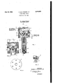
- FIG. 4 there is illustrated a slightly modifled form of relay valve in accordance with this invention.
- the plate 8a which separates chambers A and B is imperforate.
- Chamber B is provided with a fixed vent to the atmosphere but it will be understood that this vent can bemade adjustable by the use of a needle valve similar to valve I I of Fig. 1.
- the flexible diaphragm I3 instead of carrying the baille l8, carries the nozzle 29 in a position to engage the lower surface of the plate 8a which now serves as a baille.
- Compressed air at the uniform pressure supplied through the sapphire restriction ID to chamber A also passes through the adjustable restriction 30, in the form of a needle valve, and thence through the flexible conduit 3
- the operation of this modified relay valve is identical with the relay valve of Fig. 1, so that further description is unnecessary.
- Dead spot is herein defined as the largest range of values of the controlledvariable to which the measuring means or controlled means does not respond.- I v I While two forms of the present relay valve have been disclosed, it will be understood that there can be other modified forms thereof within the scope of the following claims, without departing from the spirit of the present invention.
- a hollow body means including a plate and a flexible diaphragm spaced therefrom dividing said body into a primary chamber, a secondary chamber and a tertiary chamber, a source of pressure fluid at a predetermined pressure connected to theprimary chamber through a restricted passage, said plate having an orifice therein larger than said restricted passage and permitting communication between said primary and secondary chambers, a member carried by said diaphragm and movable thereby into positions to open and close said orifice, means for supplying pressure fiuid into said tertiary chamber ata pressure throttled in accordance with a given variable, said secondary chamber being provided with a 4 restricted vent to the atmosphere of such size relative to said orifice that a substantial back pressure is provided in said secondary chamber when said orifice is open, and an output pipe communicating with said primary chamber.
- a hollow body means including a plate and a flexible diaphragm spaced therefrom dividing said body into a primary chamber, a secondary chamber and a tertiary chamber, said plate having an orifice therein permitting communication between said primary and secondary chambers, a member carried by said diaphragm and having a spheroid surface movable thereby into positions to open and close said orifice, means for supplying pressure fluid into said tertiary chamber at a pressure throttled in accordance with a given variable, said secondary chamber being provided with a restricted vent to the atmosphere of such size relative to said orifice that a substantial back pressure is, provided in said secondary chamber when said orifice is open, a source of pressure fiuid at a predetermined pressure connected to said primary chamber through a restricted passage smaller than said orifice, and an outlet pipe communicating with said primary chamber.
- a hollow body means including a plate and a flexible diaphragm spaced therefrom dividing said body into a primary chamber, a secondary chamber and a tertiary chamber, said plate having an orifice therein permitting communication between said primary and secondary chambers, a member carried by said diaphragm and movable thereby into positions to open and close said-orifice, means for supplying pressure fluid into said tertiary chamber at a pressure throttled in accordance'with a given variable, said secondary chamber being provided with an adjustable vent to the atmosphere of such size relative to said orifice that a sumtantial back pressure is provided in said secondary chamber when said orifice is open, a source of pressure fluid at a predetermined pressure connected to said primary chamber through a restricted passage smaller than said orifice, and and outlet pipe communicating with said primary chamber.
- a hollow body means including a: plate anda flexiblediaphragm spaced therefrom dividing said body into a primary chamber, a secondary chamber and a tertiary chamber, said plate having an orifice therein permitting communication between said primary and secondary chambers, a member car.- ried by said diaphragm and movable thereby into positions to open and close said orifice, and ad'- justable biasing spring tending to Opp se the movementof said diaphragm and said member toward said orifice, means for supplying pressure fluid into said tertiary chamber at a pressure throttled in accordance with a given "variable, said secondary chamber being provided with an adjustable vent to the atmosphere of'such'size relative to said orifice that a substantial, back pressure is provided in said secondary chamber when said orifice is open,-a source of pressure fluid at a predtermined' pressure connected to said primary chamber through a restricted passage smaller than said orifice, and an outlet pipe
- a hollow body means including a plate anda flexible diaphragm spaced therefrom dividing said body into a primary chamber, a secondary chamber and 5 tertiary chamber, a source of pressure fluid at a predetermined pressure connected to the primary chamber through a restricted passage, a nozzle larger than said restricted passage discharging into said secondary chamber and supplied with fluid at a pressure substantially equal to that supplied to said primary chamber, means in-- cluding said diaphragm for controlling the jdischarge of pressure fluid from said nozzle, means for supplying pressure fluid into said tertiary chamber at a pressure throttled in accordance with a given variable, said secondary chamber being provided witha vent to the atmosphere of such size relative to said nozzle that a substantial back pressure, is provided in said secondary chamber when said nozzleis open, and an output pipe communicating with a said primary chamber.
- a hollow body means including a plate and a flexible diaphragm spaced therefrom dividing saidbodyinto a primary chamber, a secondary 'chamberfand mary chamber through. a'restricted passage, a
- a source of pressure fluid at a predetermined pressure connected to the pri- [6' nozzle larger than said restricted passage discharging into saidisecondary chamber and supplied with fluid at a pressure substantially equal to that supplied to said primary chamber, said nozzle being movable by said diaphragm into various positions with respectto said plate to modify the discharge of fiuidfrom the'nozzle, means for supplying pressure fluid into said tertiary chamber at 'a pressure throttled in accordv ance with a given variable, said secondary chamher being provided with a vent to atmosphere of such size relative to said nozzle that a substantial back pressure is providedin said secondary chamber when said nozzle is open, and an output pipe with a said primary chamber.
Description
1952 s. s. Dl MAGGIO, JR 2,614,583
- PILOT RELAY VALVE Filed Aug. 18, 1949 P UMA ALLY ER ED VICE AIR SUPPLY 6 AT UNIFORMF PRESSURE L 7 u l5 7% v v r THR n 7/ AIR H FIG. I
IN VEN TOR.
BY A).
ATTO RN EY SAMUEL S. DI MAGGIO JR.
pressure in the chamber B, plus the force of the sprin 22, the diaphragm raises the baffle [B so that it begins to seal oif the nozzle [2. As the nozzle is being thus sealed oif the pressure in chamber B decreases rapidly, approaching zero value thereby allowing the diaphragm [3 to snap the baiiie I8 upward into engagement with the nozzle I2 to completely seal the same.
The set point or the distance between the noz zle and baifie is normally maintained at .010". by means of the adjusting nut 26. The provision of the adjusting nut permits various desired adjustments of the set-point of the relay valve within the range of the biassing spring 22'while maintaining the same dead spot or dead range for this valve. On the other hand, if it is desired to maintain a given set-point of the relay valve, the dead range thereof can be adjusted at will by various adjustments of the needle valve I! which serves to increase or decrease as desired, the back pressure in the chamber 3. However, this means that the minimum operating pressure will be equal to the pressure in chamber B. It is obvious, of course, that with no back pressure in chamber B, the output air pressure can be throttled. Increasing or decreasin the capacity of chamber A, will directly affect the time in which full output pressure is obtained.
InFig. 4, there is illustrated a slightly modifled form of relay valve in accordance with this invention. In this form, the plate 8a which separates chambers A and B is imperforate. Chamber B is provided with a fixed vent to the atmosphere but it will be understood that this vent can bemade adjustable by the use of a needle valve similar to valve I I of Fig. 1. In this form of the invention, the flexible diaphragm I3, instead of carrying the baille l8, carries the nozzle 29 in a position to engage the lower surface of the plate 8a which now serves as a baille. Compressed air at the uniform pressure supplied through the sapphire restriction ID to chamber A, also passes through the adjustable restriction 30, in the form of a needle valve, and thence through the flexible conduit 3| to the nozzle 29. The operation of this modified relay valve is identical with the relay valve of Fig. 1, so that further description is unnecessary.
Dead spot is herein defined as the largest range of values of the controlledvariable to which the measuring means or controlled means does not respond.- I v I While two forms of the present relay valve have been disclosed, it will be understood that there can be other modified forms thereof within the scope of the following claims, without departing from the spirit of the present invention.
What I claim is:
1. In a device of the class described, a hollow body, means including a plate and a flexible diaphragm spaced therefrom dividing said body into a primary chamber, a secondary chamber and a tertiary chamber, a source of pressure fluid at a predetermined pressure connected to theprimary chamber through a restricted passage, said plate having an orifice therein larger than said restricted passage and permitting communication between said primary and secondary chambers, a member carried by said diaphragm and movable thereby into positions to open and close said orifice, means for supplying pressure fiuid into said tertiary chamber ata pressure throttled in accordance with a given variable, said secondary chamber being provided with a 4 restricted vent to the atmosphere of such size relative to said orifice that a substantial back pressure is provided in said secondary chamber when said orifice is open, and an output pipe communicating with said primary chamber.
2. In a device of the class described, a hollow body, means including a plate and a flexible diaphragm spaced therefrom dividing said body into a primary chamber, a secondary chamber and a tertiary chamber, said plate having an orifice therein permitting communication between said primary and secondary chambers, a member carried by said diaphragm and having a spheroid surface movable thereby into positions to open and close said orifice, means for supplying pressure fluid into said tertiary chamber at a pressure throttled in accordance with a given variable, said secondary chamber being provided with a restricted vent to the atmosphere of such size relative to said orifice that a substantial back pressure is, provided in said secondary chamber when said orifice is open, a source of pressure fiuid at a predetermined pressure connected to said primary chamber through a restricted passage smaller than said orifice, and an outlet pipe communicating with said primary chamber.
3. In a device of the class described, a hollow body, means including a plate and a flexible diaphragm spaced therefrom dividing said body into a primary chamber, a secondary chamber and a tertiary chamber, said plate having an orifice therein permitting communication between said primary and secondary chambers, a member carried by said diaphragm and movable thereby into positions to open and close said-orifice, means for supplying pressure fluid into said tertiary chamber at a pressure throttled in accordance'with a given variable, said secondary chamber being provided with an adjustable vent to the atmosphere of such size relative to said orifice that a sumtantial back pressure is provided in said secondary chamber when said orifice is open, a source of pressure fluid at a predetermined pressure connected to said primary chamber through a restricted passage smaller than said orifice, and and outlet pipe communicating with said primary chamber. H I
4. Ina device of the class described, a hollow body, means including a: plate anda flexiblediaphragm spaced therefrom dividing said body into a primary chamber, a secondary chamber and a tertiary chamber, said plate having an orifice therein permitting communication between said primary and secondary chambers, a member car.- ried by said diaphragm and movable thereby into positions to open and close said orifice, and ad'- justable biasing spring tending to Opp se the movementof said diaphragm and said member toward said orifice, means for supplying pressure fluid into said tertiary chamber at a pressure throttled in accordance with a given "variable, said secondary chamber being provided with an adjustable vent to the atmosphere of'such'size relative to said orifice that a substantial, back pressure is provided in said secondary chamber when said orifice is open,-a source of pressure fluid at a predtermined' pressure connected to said primary chamber through a restricted passage smaller than said orifice, and an outlet pipe communicating with said primary chamber.
5. In a device of the class-described, a hollow body. means including a plate anda flexible diaphragm spaced therefrom dividing said body into a primary chamber, a secondary chamber and 5 tertiary chamber, a source of pressure fluid at a predetermined pressure connected to the primary chamber through a restricted passage, a nozzle larger than said restricted passage discharging into said secondary chamber and supplied with fluid at a pressure substantially equal to that supplied to said primary chamber, means in-- cluding said diaphragm for controlling the jdischarge of pressure fluid from said nozzle, means for supplying pressure fluid into said tertiary chamber at a pressure throttled in accordance with a given variable, said secondary chamber being provided witha vent to the atmosphere of such size relative to said nozzle that a substantial back pressure, is provided in said secondary chamber when said nozzleis open, and an output pipe communicating with a said primary chamber.
6. In a device of the class described, a hollow body, means including a plate and a flexible diaphragm spaced therefrom dividing saidbodyinto a primary chamber, a secondary 'chamberfand mary chamber through. a'restricted passage, a
,tertiarychamber, a source of pressure fluid at a predetermined pressure connected to the pri- [6' nozzle larger than said restricted passage discharging into saidisecondary chamber and supplied with fluid at a pressure substantially equal to that supplied to said primary chamber, said nozzle being movable by said diaphragm into various positions with respectto said plate to modify the discharge of fiuidfrom the'nozzle, means for supplying pressure fluid into said tertiary chamber at 'a pressure throttled in accordv ance with a given variable, said secondary chamher being provided with a vent to atmosphere of such size relative to said nozzle that a substantial back pressure is providedin said secondary chamber when said nozzle is open, and an output pipe with a said primary chamber.
communicating SAMUEL S. D1 MAGGIO, JR.
REFERENCES CI TED' The following references are of record in the file of this patent:
UNITED STATES PATENTS I Number Name Date f 1,680,750 Smoot Aug. 14,1928 2,386,108 Gess i Oct. 2, 1945'
Priority Applications (1)
| Application Number | Priority Date | Filing Date | Title |
|---|---|---|---|
| US110985A US2614583A (en) | 1949-08-18 | 1949-08-18 | Pilot relay valve |
Applications Claiming Priority (1)
| Application Number | Priority Date | Filing Date | Title |
|---|---|---|---|
| US110985A US2614583A (en) | 1949-08-18 | 1949-08-18 | Pilot relay valve |
Publications (1)
| Publication Number | Publication Date |
|---|---|
| US2614583A true US2614583A (en) | 1952-10-21 |
Family
ID=22335993
Family Applications (1)
| Application Number | Title | Priority Date | Filing Date |
|---|---|---|---|
| US110985A Expired - Lifetime US2614583A (en) | 1949-08-18 | 1949-08-18 | Pilot relay valve |
Country Status (1)
| Country | Link |
|---|---|
| US (1) | US2614583A (en) |
Cited By (5)
| Publication number | Priority date | Publication date | Assignee | Title |
|---|---|---|---|---|
| US2907605A (en) * | 1957-10-29 | 1959-10-06 | Sun Oil Co | Apparatus for transfer of solids between zones of different pressures |
| US3077122A (en) * | 1957-07-29 | 1963-02-12 | Gen Motors Corp | Transmission |
| US3300176A (en) * | 1964-06-24 | 1967-01-24 | Foxboro Co | Digital operator |
| US3831616A (en) * | 1972-03-13 | 1974-08-27 | Parke Davis & Co | Novel liquid control system |
| US4860787A (en) * | 1986-01-15 | 1989-08-29 | Imaje, S.A. | Pressure regulator with integrated sensor |
Citations (2)
| Publication number | Priority date | Publication date | Assignee | Title |
|---|---|---|---|---|
| US1680750A (en) * | 1926-10-22 | 1928-08-14 | Charles H Smoot | Regulator |
| US2386108A (en) * | 1945-10-02 | Measuring instrument |
-
1949
- 1949-08-18 US US110985A patent/US2614583A/en not_active Expired - Lifetime
Patent Citations (2)
| Publication number | Priority date | Publication date | Assignee | Title |
|---|---|---|---|---|
| US2386108A (en) * | 1945-10-02 | Measuring instrument | ||
| US1680750A (en) * | 1926-10-22 | 1928-08-14 | Charles H Smoot | Regulator |
Cited By (5)
| Publication number | Priority date | Publication date | Assignee | Title |
|---|---|---|---|---|
| US3077122A (en) * | 1957-07-29 | 1963-02-12 | Gen Motors Corp | Transmission |
| US2907605A (en) * | 1957-10-29 | 1959-10-06 | Sun Oil Co | Apparatus for transfer of solids between zones of different pressures |
| US3300176A (en) * | 1964-06-24 | 1967-01-24 | Foxboro Co | Digital operator |
| US3831616A (en) * | 1972-03-13 | 1974-08-27 | Parke Davis & Co | Novel liquid control system |
| US4860787A (en) * | 1986-01-15 | 1989-08-29 | Imaje, S.A. | Pressure regulator with integrated sensor |
Similar Documents
| Publication | Publication Date | Title |
|---|---|---|
| GB942742A (en) | Improvements in or relating to gas filtration plant | |
| GB1208765A (en) | Air distribution unit | |
| US2614583A (en) | Pilot relay valve | |
| GB783169A (en) | Pressure fluid operated balanced control system | |
| GB1179433A (en) | Apparatus for producing Short Duration Blasts of High Pressure Gaseous Fluid from the Discharge Outlet of a Valve Connected to a High Pressure Supply Line | |
| US2311061A (en) | Governor valve mechanism | |
| US2873756A (en) | Device for controlling an actuator by the translation of a shock wave | |
| GB624932A (en) | Improvements in air distributor devices | |
| US2302023A (en) | Oxygen delivery apparatus | |
| GB1428887A (en) | Pneumatic transducer for converting mechanical displacement of responsive element into pneumatic signal | |
| GB624616A (en) | Improvements in regulating valves | |
| GB248102A (en) | An improved device to control gas-lighting from a distance | |
| GB1016558A (en) | Pneumatic control device | |
| GB625055A (en) | Improvements in or relating to apparatus for metering the fuel supplied to a prime mover | |
| GB707630A (en) | Improvements in or relating to pneumatic control systems | |
| GB671690A (en) | Improvements in or relating to fluid flow controlling valve apparatus | |
| GB630454A (en) | Regulating means for liquid fuel pumps | |
| GB746068A (en) | Improvements relating to the supply of fuel to liquid fuel burners | |
| GB617382A (en) | Improvements relating to heating and ventilation systems | |
| GB850221A (en) | Improvements in or relating to pneumatic force-balance controllers | |
| GB615930A (en) | Improvements in or relating to fluid flow valves or governors | |
| GB877084A (en) | Improvements in or relating to pneumatic process control systems | |
| GB687677A (en) | Improved pressure control apparatus for use with steam generators | |
| GB702864A (en) | Improvements in or relating to thermostatic control devices sensitive to steam or vapour temperature | |
| GB669599A (en) | Improvements in or relating to fluid flow control valve apparatus |