US2849986A - Hydraulic control mechanism for planing machines - Google Patents
Hydraulic control mechanism for planing machines Download PDFInfo
- Publication number
- US2849986A US2849986A US53322355A US2849986A US 2849986 A US2849986 A US 2849986A US 53322355 A US53322355 A US 53322355A US 2849986 A US2849986 A US 2849986A
- Authority
- US
- United States
- Prior art keywords
- piston
- pressure
- oil
- drillings
- annular channel
- Prior art date
- Legal status (The legal status is an assumption and is not a legal conclusion. Google has not performed a legal analysis and makes no representation as to the accuracy of the status listed.)
- Expired - Lifetime
Links
Images


Classifications
-
- F—MECHANICAL ENGINEERING; LIGHTING; HEATING; WEAPONS; BLASTING
- F15—FLUID-PRESSURE ACTUATORS; HYDRAULICS OR PNEUMATICS IN GENERAL
- F15B—SYSTEMS ACTING BY MEANS OF FLUIDS IN GENERAL; FLUID-PRESSURE ACTUATORS, e.g. SERVOMOTORS; DETAILS OF FLUID-PRESSURE SYSTEMS, NOT OTHERWISE PROVIDED FOR
- F15B13/00—Details of servomotor systems ; Valves for servomotor systems
- F15B13/02—Fluid distribution or supply devices characterised by their adaptation to the control of servomotors
- F15B13/04—Fluid distribution or supply devices characterised by their adaptation to the control of servomotors for use with a single servomotor
- F15B13/0416—Fluid distribution or supply devices characterised by their adaptation to the control of servomotors for use with a single servomotor with means or adapted for load sensing
- F15B13/0417—Load sensing elements; Internal fluid connections therefor; Anti-saturation or pressure-compensation valves
-
- B—PERFORMING OPERATIONS; TRANSPORTING
- B23—MACHINE TOOLS; METAL-WORKING NOT OTHERWISE PROVIDED FOR
- B23Q—DETAILS, COMPONENTS, OR ACCESSORIES FOR MACHINE TOOLS, e.g. ARRANGEMENTS FOR COPYING OR CONTROLLING; MACHINE TOOLS IN GENERAL CHARACTERISED BY THE CONSTRUCTION OF PARTICULAR DETAILS OR COMPONENTS; COMBINATIONS OR ASSOCIATIONS OF METAL-WORKING MACHINES, NOT DIRECTED TO A PARTICULAR RESULT
- B23Q5/00—Driving or feeding mechanisms; Control arrangements therefor
- B23Q5/22—Feeding members carrying tools or work
- B23Q5/26—Fluid-pressure drives
-
- B—PERFORMING OPERATIONS; TRANSPORTING
- B23—MACHINE TOOLS; METAL-WORKING NOT OTHERWISE PROVIDED FOR
- B23Q—DETAILS, COMPONENTS, OR ACCESSORIES FOR MACHINE TOOLS, e.g. ARRANGEMENTS FOR COPYING OR CONTROLLING; MACHINE TOOLS IN GENERAL CHARACTERISED BY THE CONSTRUCTION OF PARTICULAR DETAILS OR COMPONENTS; COMBINATIONS OR ASSOCIATIONS OF METAL-WORKING MACHINES, NOT DIRECTED TO A PARTICULAR RESULT
- B23Q2705/00—Driving working spindles or feeding members carrying tools or work
- B23Q2705/10—Feeding members carrying tools or work
- B23Q2705/12—Fluid-pressure drives
- B23Q2705/125—Fluid-pressure drives for planing machines
-
- Y—GENERAL TAGGING OF NEW TECHNOLOGICAL DEVELOPMENTS; GENERAL TAGGING OF CROSS-SECTIONAL TECHNOLOGIES SPANNING OVER SEVERAL SECTIONS OF THE IPC; TECHNICAL SUBJECTS COVERED BY FORMER USPC CROSS-REFERENCE ART COLLECTIONS [XRACs] AND DIGESTS
- Y10—TECHNICAL SUBJECTS COVERED BY FORMER USPC
- Y10T—TECHNICAL SUBJECTS COVERED BY FORMER US CLASSIFICATION
- Y10T137/00—Fluid handling
- Y10T137/8593—Systems
- Y10T137/87169—Supply and exhaust
- Y10T137/87217—Motor
- Y10T137/87225—Fluid motor
Description
Sept. 2, 1958 F. KLOPP 2,849,986
HYDRAULIC CONTROL MECHANISM FOR PLANING MACHINES Filed Sept. 8, 195's 4 Sheets-Sheet 1 Sept. 2, 1958 F. KLQPP 2,
HYbRAuuc CONTROL MECHANISM FOR PLANING MACHINES Filed Sept. 8, 1955 4 Sheets-Sheet 2 Sept. 2, 1958 F. KLOPP 2,849,986
HYDRAULIC CONTROL MECHANISM FOR PLANING MACHINES Filed Sept. 8, 1955 4 Sheets-Sheet 3 Sept. 2, 1958 F. KLOPP 2,849,986
HYDRAULIC CONTROL MECHANISM FOR PLANING MACHINES Filed Sept. 8, 1955 4 Sheets-Sheet 4 uvnewroe $4M Kg United Sttes atent Ofiice HYDRAULIC CONTROL MECHANISM FOR PLANING MACHINES Friedrich Klopp, Solingen-Wald, Germany Application September 8, 1955, Serial No. 533,223
Claims priority, application Germany September 11, 1954 14 Claims; (Cl. 121-45) The invention relates to a hydraulic control for planing machines for controlling. the double-action operating cylinder supplied by a pump. The control is provided with an advancing member controllable from the operative movement of the tool or workpiece carriage for example by abutments, a main control member for supplying oil to one of the piston sides of the operating piston and a rotary member for establishing the oil circuit or discharging the oil to a reservoir.
The known hydraulic controls for planing machines undergo reactions to a large extent due to alteration of the cutting pressures, so that the so-called screening occurs. The working surface is thus impaired or the operating time increased. Moreover, the tools are subjected to high strains.
The invention has the object of providing a hydraulic control in which these fluctuations due to momentary alterations of the cutting pressure are taken by up by the hydraulic control, so that a smoother run of the tool and hence a smoother operating surface are given, which is free from swinging tool effects or so-called chatter marks.
According to the invention, in the advance of the tool into the decreasing cylinder space of the operating piston, a counterpressure is produced, which varies automatically in dependence upon the cutting pressure. The counterpressure is in a definite ratio to the pressure acting on the piston side supplied on advance from the pump and proportional to the cutting force. This ratio is given, for example, by the dimensions of the control surfaces transmitting and/or causing the counterpressure.
In one embodiment of the invention, the counterpressure is produced by throttling the discharging oil. The throttle device stands in the path. of the oil discharging on advance of the operating piston. A throttle position is located for example by arranging behind the throttle arrangement a pressure cushion or hydraulic lock which is not variable under the influence of swinging due to fluctuations of the cutting force.
In one constructional form, a control device is arranged on the main control member and movable to it, having three mutually sealed pressure surfaces for the action of the oil. The control device consists, for example, of a piston surrounding the main control member, one end face of which, preferably equipped with a throttle section, is movable into the path of the oil discharging from the operating piston. The other end face of the piston surrounding the main control member is constructed in step fashion. The step height between the two end faces so produced is greater than the greatest possible movement of the piston and is arranged to receive sealing means between the two end faces formed by the step-like construction. The two end faces constructed on one side of the piston surrounding the main control member are constructed in different sizes. The smaller is actuated on advance by the oil supplied from the pump and shifts the piston or its other end into the path of flow of the discharging oil. Behind. the other end face of the step-like, staggered end of the pistonsurrounding the main control member, a cylindrical space is formed, which communicates with the discharging oil by way of a check valve. The discharging oil has to overcome a slight counterpressure on entering the reservoir, which ensures that the cylindrical space behind one pressure surface of the piston arranged on the main control member is filled on shifting thereof. The arrangement is constructed so that the piston surrounding the main control shaft is operated simultaneously with shifting of the main control member on conducting. the pressure medium supplied from the pump to one or other side of the operating piston. Since in controlling the back-flow of the oil from one side of the operating cylinder'is first shut off by the control piston, whereas the pump continues to supply to the other side of the. operating cylinder, a pressure increase is set up for controlling. the main control member, which also acts on the piston arranged on the main control member.
In another constructional form, the throttle arrangement in the hydraulic control is provided in the form of an additional valve which is arranged in the duct through which the oil discharges on advance of the operating piston. The possibility is thus given of installing the, device of the invention in existing control devices without. considerable expense.
Whereas throttling-of the discharging oil is particularly recommendable in planing off, since this operation. is liable. to cause considerable swinging, the counterpressure in. smoothing operations is conveniently produced in another way. A circuit of the oil from one side to the other of the operating piston is closed, so that the operating piston is acted upon at both of its end faces.
On. advance, the oil in the hydraulic control device discharging from the forward piston side of, the operating piston is led into the oil supplied to the. other side of the operating piston, so that both end faces of the operating piston are under the same pressure. and they cutting pressure is given from the difference of the effective surfaces of the two piston sides. A difference is produced by the piston rod engaging one side of the operating piston, so, that an excess pressure for the operation is always provided for. In this embodiment, the operating piston is acted upon and safely guided at. both sides, so that fluctuations are suppressed.
Conversion'of the path of flow for carrying out one or other controlling principle is caused by moving the rotary member, by which an annular space in the member is brought. into the path of the discharging oil. Grooves extend from this annular space to the region which is in communication with the path of the oil supplied from the pump.
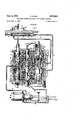
The invention is described with reference to different embodiments shown in the accompanying drawings, in which: 7
Figs. 1 to 4 show a hydraulic control device in section, wherein Fig. 1 shows the control position for the advance. in planing otf,
Fig. 2 shows the control position for the return stroke in planing oif,
Fig. 3 shows the control position for the advance in smoothing,
Fig. 4 shows the control position for return stroke in smoothing;
Fig. 5 shows the additional valve for throttling the oil discharging on advance.
The mode of operation is as follows:
Three valve members are located in a control housing 1. The advancing member 2 is governed by abutments 4, 5 adjustably mounted on the pedestal or work table 3 by way of a cranked lever 6 into its end positions, which are limited by a screw 7 or nut 8 on the washer 9. A hydraulic movement of the main control member 10 is thus effected, which causes the liquid stream to be conducted from the forward piston side 12 to the rear piston side 11 or vice versa and hence controls the pedestal or work table movement. The rotary member 13 has the purpose of leading the oil supplied from the pump 14 either to the operation pressure in the hydraulic circuit or into the reservoir on shut-down of the machine. By moving this rotary member 13 in the longitudinal direction, a differential adjustment is obtained as explained in more detail below (Figs. 3 and 4).
Fig. 1 shows the control position for the advance of the ram in the control stage I, i. e. planing off. The rear piston side 11 is hence fully subjected to the oil, whereas the oil from the front piston side 12 returns to the reservoir 64. The operation is as follows:
The advancing member 2 is moved into its upper end position and the oil supplied from the piston 14 through the duct 15 into the annular channel 16 can pass through the control bushing drilling 17, the transverse drilling 18, the longitudinal drilling 19, the transverse drilling 20, the control bushing drilling 21, the annular channel 22, the passage 23, the annular channel 24, the passage 25, the annular channel 26 and the drillings 27 into the cylindrical space 28 and moves the main control member 10 into the position shown. The oil further supplied from the pump 14 passes through the passage 29, the annular channel 30, the passage 31, the annular channel 32, the control bushing drillings 33, the annular space 34 in the piston, the drilling 35, the annular channel 36 and the duct 37 into the cylindrical space 38 and the oil pressure moves the ram 3 forwardly (see arrows) by way of the piston rod 39.
The oil displaced by the forward movement of the piston at the piston side 12 from the cylindrical space 40 returns by way of the duct 41, the annular channel 42, the drilling 43, the annular space 44 in the piston, the drillings 45, the annular channel 46, the passage 47, the annular channel 48, the passage 49, the annular channel 50, the drillings 51, the annular space 52 in the piston, the drillings 53, the annular channel 54, the passage 55, the annular channel 56, the two drillings 57, the space 58, the drillings 59, the annular channel 60, the connection 61 and the duct 62 to the reservoir 64 against a slight counterpressure (0.5 to 0.8 atmospheres) of the check valve 63.
If the cutting pressure and hence the oil pressure in the cylindrical space 38 increase, this pressure, which also prevails in the space 28, is passed through the drillings 65, 66 and 67 at the annular cross-section 68 of a piston 69 arranged above the main control member 10 and moves this piston 69 downwardly by way of the drillings 45. The oil discharging from the cylindrical space 40 is thus throttled, and a back-pressure arises at the piston crosssection 44 and the piston surface 12 which opposes the cutting force. This back-pressure should be maintained as small as possible, so that the losses arising remain within reasonable limits. The back-pressure urges the piston 69 against the force which acts upon the circular crosssection 68 until both forces are in equilibrium. Since the surfaces of the cross-sections 44 and 68 are not of equal size, but are in a definite ratio, after establishing the equilibrium of the forces, the corresponding liquid pressures act inversely as the surface cross-sections, that is, the counterpressure on the piston surface 12 is smaller than the pressure acting upon the piston surface 11 in the ratio of the surface 68 to the surface 44.
If the cutting pressure fluctuates during the operation through varying material strengths, non-uniform cutting strengths or through swinging, which occur in the shaping operation, the ram or work table would start to vibrate and screen marks would form on the work-piece. With the fluctuating cutting pressure, the throttle strength at the drillings 45 would also vary, so that the counterpressure on the piston surface 12 would likewise vary corresponding to the fluctuating cutting pressure. The counterpressure on the piston surface 12 should suppress any swinging movement, so that no screen marks can be formed. For this reason, care must be taken that the counterpressure always remains the same despite fluctuating cutting pressure. An oil cushion is consequently provided behinded the piston 69 in the space 70, which no longer permits the piston to recede from the initially adjusted position, which corresponds to a throttling associated with the cutting pressure, so that counterpressure can suppress the swinging. The cushion oil is led off from the oil returning to the reservoir against the slight pressure of the check valve 63 and is supplied to the space 70 by way of the space 58, the rotary member transverse drillings 71, the longitudinal drilling 72, the transverse drillings 73, the annular space 74, the drillings 75, the annular channel 76, the passage 77, the annular channel 78, the drillings 79, the annular channel 80, the drilling 81 by way of the check valve 82, the annular channel 83, the drilings 84, the longitudinal drilling 85, the drillings 86, the annular channel 87 and the drillings 88. The oil acts as a cushion and so prevents the piston 69 from undergoing return movement (movement upwardly), since it can no longer escape from the space 70 against the check valve 82. The previously established throttling of the oil discharging from the cylindrical space 40 is thus maintained at the drillings 54 and the counterpressure at the piston surface 12 hence remains constant despite fluctuating cutting pressure. By these measures, screening of the ram or work table no longer occurs, as is determined by tests.
The oil displaced from the space 89 in controlling the main control member 10 returned to the reservoir 64 by way of the drillings 90, the annular channel 91, the passage 92, the annular channel 93, the passage 94. the annular channel 95, the drillings 96, the space 97, the drillings 98, the annular channel 99. the passage 100, the annular channel 76, the drillings 75, the space 74, the drillings 73, 72, 71, the space 58, the drillings 59, the annular channel 60, the connection 61 and the duct 62 through the check valve 63.
The piston rings 101 serve to seal the annular piston space 44 from the space 68. The piston rings 102 seals the space 70 from the space 89 and the sealing ring 103 seals the space 69 from the space 70. The damping cones arranged at the ends of the main control member 10 brake the control movement (movement of the piston 10) and so ensure a smooth ram or work table reversal at the forward and rearward ends of the stroke Fig. 2 shows the control position for the return stroke of the ram in the operation I, planing off. The forward piston side 12 is fully subjected to the oil, whereas the oil displaced from the rear piston side 11 at the cylindrical space 38 discharges into the reservoir 64. Operation is as follows:
The advancing member 2 moves from the upper end position shown in Fig. l to the lower end position shown in Fig. 2 and so shuts off the oil discharging from the forward cylindrical space 40 from returning to the drillings 51, so that the ram can no longer move forwardly. The oil supplied from the pump 14 is led into the rear cylindrical space 38 and presses upon the piston sur face 11. Since no oil can fiow from the forward cylindrical space 40, an increase in pressure occurs in the hydraulic circuit. This pressure passes from the pump 14 by way of the duct 15, the annular channel 16, the drillings 17, the drillings 104, 105 and 106, the annular space 97 in the piston, the drillings 96, the annular channel 95, the passage 94, the annular channel 93, the passage 92, the annular channel 91 and the drillings into the cylindrical space 89 and moves the main control member 10 down into the position shown. In
this movement, the maincontrol member forces the oil located in the cylindrical space 28 by way of the drillings 27, the annular channel 26, the passage 25, the annular channel 24, the passage 23, the annular channel 22, the drillings 21, the annular space 107 in the piston, the drillings 108, the annular channel 109, the passage 110, the annular channel 60, the connection 61 and the duct 62 through the check valve 63 back into the reservoir 64. The oil supplied from the pump 14 is fed through the duct 15, the annular channel 16, the passage 29, the annular channel 30, the passage 31, the annular channel 32, the drillings 33, the annular space 44 in the piston, the drillings 43, the annular channel 42 and the duct 41 into the cylindrical space 40 and acts upon the piston surface 12, so returning the ram .3 by means of the piston rod 39. The oil thus displaced from the cylindrical space 38 returns to the reservoir 64 by way of the duct '37, the annular channel 36, the drillings 35, the .annular space .34 in the piston, the drillings .111, the annular channel 112, the
passage 113, the annular channel .114, the passage 115,
the annular channel 116, the drillings .117, the annular space 118 in the pistonythe drillings 119, the annular channel 120, the passage 121, the annular channel 122, the two drillings 123, the annular space 58, the drillings 59, the annular channel 60, the connection 61 and the duct 62 against the pressure of the check valve 63.
The cushion of oil located behind the throttle piston 69 in the piston space 70 at the beginning of the control of the main control member 10, Which cannot escape through the check valve 82, flows back to the reservoir 64, after the drilling 84 is freed by the annular channel 124 through the drillings 8,8, the annular channel 87, the drillings 86, the longitudinal drilling 85, the drillings 84, the annular channel 124 and the drilling 125. The piston 69 is pushed back by the return pressure which acts upon the annular surface 44 against .the pressure free piston space 6.8 into itsyrest position shown, so that it remains ineffective during the return stroke. Effectiveness is not required, since during the return stroke no removal of cuttings takes place and so screening cannot occur. Only an additional loading and hence unnecessary heating of the driving oil would be connected with throttling.
Figure 3 shows the control position for the advance of the ram in the stage II, smoothing off. The rear piston side 11 is fully acted upon by the oil, whereas the oil displaced from the forward cylindrical space 40 is fed by the control to the rear cylindrical space .38 in addition to the oil supplied from the pump 14. Operation is as follows:
The rotary member 13 is movedin the longitudinal direction into the position shown. The advancing member 2 moves from the downward end positionshown in Fig. 2
to the upper end position shown in Fig. 3 and hence prevents the oil discharging from the rear cylindrical space 38 from returning to the drillings 117, so that the ram can no longer run rearwardly. The oil supplied from the pump 14 is again led into the forward cylindrical space' 40 and presses upon the piston surface 12. Since oil can no longer flow from the rear cylindrical space, an increase in pressure occurs in the hydraulic circuit. This pressure advances from the pump 14 to the duct 15 through the annular channel 16 and into the cylindrical space 23 in the way describedin connection with Fig. 1 and moves the main control member 10 into the upper position shown. The oil further supplied from the pump '14 moves the ram 3 forward in the way already described. The oil discharging from the forward cylindrical space 40 returns to the circuit through the ,duct 41, the annular channel 42, the drillings 45, the annular channel .46, the passage .47, theannular channel 48, the
passage 49, the annular channel 50, the drillings 51, the annular space 52 in the piston, the drillings 53, the annular channel ,54, the passage .55, the annular channel .56, the two drillings 57, the annular space. 126, the grooves and the bushing borings 128 and, together with the oil supplied from the pump 14, is conducted in the way already described in connection with the advance in planing off into the cylindrical space 38. Since in this operation the same liquid pressure prevail-s in both cylindrical spaces 38 and 40, the pressure can only beeifective on the surface difference of the piston surface 11 minus the piston surface 12. This effective cross-section is equal to the surface of the piston rod 39. In this operation, a higher ram velocity at one part of the effective cutting pressure is dispensed with. This is directly feasible since with increased cutting velocities substantially thinner cuttings can be planed off. In this operative stage, no throttling of the liquid returning from the cylindrical space 40 to the'drilling 45 by the piston 69 takes place, since the pressure in the piston space 68 is approximately as large as in the piston space 44,-so that the piston 69 cannot move down since the piston surface 44 is greater than the piston surface 68. Throttling is also not necessary, since as explained above a counter-pressure is present and in this operation If, only thin cuttings-are'planed off, so that screening does not occur, as was proved by tests.
Figure 4 shows the control position for the return of the ram in the operation II, smoothing off. The forward piston side 12 is fully subject to pressure, whereas the oil displaced from the rear piston side 11 from the cylindrical space 38 returns to the reservoir 64 and proceeds exactly as described above in connection with the planing off return stroke, except that the middle rotary member 13 is moved longitudinally into the position shown.
In Fig. 5, the additional valve is illustrated which can be included in an existing hydraulic'control device. This additional valve consists of a housing 129 with a cylindrical space which is surrounded by a bushing 130. A piston 131 is slidably mounted in the cylindrical space. This piston has two grooves of different cross-sections, whereby a circular end face 132 andan annular pressure surface 133 are formed at one side of the piston. The groove in the piston of smaller diameter is guided in a bushing 134 suited to this diameter. the housing wall of the bushing is closed olf. Dirt-catching grooves 135 are arranged on the circumference of the piston. Sealing of the piston in'the cylindrical bushing is effected by packing. A member 136 movable in a guide 137 is arranged by the cylinder for the piston 131. Connecting channels 138, 139 and 140 to the separate pressure surfaces of the piston 131 open into this guide. The member 136 has a reduced'portion 141 in its middle section which is so arranged that it connects the channel 139 with a discharge opening 142,when the member 136 is disposed in its left-hand end position.
The additional valve is so arranged that theconnection openings 143 and 144 lie in the pressure medium duct by which the oil is supplied to the operating cylinder on return of the ram. In this case, which is also illustrated in the drawings, the piston 131 is forced into its lefthand end position. The connection 145 entering the cylindrical region in front of the step-like pressure surface 133, which is closed by a check valve 146, communicates with the discharge tube of the control device, for example the tube 62 shown 'inFigs. 1 to 4. Supply to the cylindrical space above the piston surface 132 takes place through the connection union 147. A duct is connected to this union which feeds the oil supplied fromtheipurnp on advance.
On advance in planing off, oil is forced through the connection 147 to the guide of the member136 and shifts the member to the right. This oil thus flows through the channel 138 into the cylindrical space above the piston surface 132 and urges the piston 131 to the right. The cylindrical space above the annular piston surface133 hence enlarges and oil discharging from the operating :cylinder, which is under a certain counterpressure due .for
The end abutting example to the location of the counterpressure valve, flows into this cylindrical space by overcoming the check valve 146. The piston 131 is still subject to the oil flowing in through the opening 143 and discharging through the connection 144, which flows from the operating cylinder into the reservoir. Since the side of the piston 131 facing the connection 143 is larger than the pressure side 132, which is subject to the oil supplied from the pump, the piston 131 stands in a position in which one forward edge of the connecting opening between the connections 143 and 144 is partly covered and hence throttled. If fluctuations of the cutting pressure now occur, these fluctuations do not lead to alteration of the throttle position, since the piston 131 cannot return since the pressure cushion established behind the pressure surface 133 cannot discharge clue to the arrangement of the check valve 146.
The additional valve is only returned to the position shown in Fig. 5 after setting the operating piston. Since the oil supplied from the pump flows through the connections 144 and 143 and the connection 147 communicates with the oil discharging to the reservoir, the control member 136 is forced to the left. The reduced portion 141 opens the cylindrical space above the pressure surface 133 to the discharge line 142, so that the piston 131 can also be moved to the left.
What I claim is:
1. A hydraulic control for planing machine carriages comprising a double-action operating cylinder and piston means for moving to and fro the carriage of the planing machine, pilot valve means governed in dependence upon the operative movement of said carriage by abutment means, a main reversing valve means for directing pres sure fluid to one of the piston sides of said operating piston, a bypass valve means for establishing a hydraulic circuit and discharging the hydraulic fluid into a reservoir, means for creating a counterpressure acting upon the other side of said operating piston and means regulating said counterpressure means throughout the working movement of the carriage commensurate with the maximum fluid pressure exerted on the first side of said operating piston.
2. A hydraulic control for planing machines carriages comprising a double-action operating cylinder and piston means for moving to and fro the carriage of the planing machine, pilot valve means governed in dependence upon the operative movement of said carriage by abutment means, a main reversing valve means for directing pressure fluid to one of the piston sides of said operating piston, a by-pass valve means for establishing a hydraulic circuit and discharging the oil into a reservoir, and means for creating a counter-pressure throughout the working movement of the carriage acting upon the other piston side, in a definite ratio to the maximum pressure acting upon the first mentioned piston side and proportional to the cutting force.
3. A hydraulic control for planing machines carriages comprising a double-action operating cylinder and piston means for moving to and fro the carriage of the planing machine, pilot valve means governed in dependence upon the operative movement of said carriage by abutment means, a main reversing valve means for directing pressure fluid to one of the piston sides of said operating piston, a by-pass valve means for establishing a hydraulic circuit and discharging the oil into a reservoir, means for creating a backpressure acting upon the other piston side, means controlling said backpressure creating means whereby said backpressure means is rendered effective to increase the resistance to flow within the discharge connection of said cylinder on an increase in pressure in the supply connection of said cylinder and to thereby increase the backpressure in proportion to the increase in resistance to movement of said reciprocated carriage by which the increase in pressure in the supply connection was occasioned, and a hydraulic lock means effective to prevent movement of the backpressure means to decrease the resistance to flow in said discharge connection, upon a decrease from the maximum pressure of the supply connection.
4. A hydraulic control for planing machines carriages comprising a double-action operating cylinder and piston means for moving to and fro the carriage of the planing machine, pilot valve means governed in dependence upon the operative movement of said carriage by abutment means, a main reversing valve means for directing pressure fluid to one of the piston sides of said operating piston, a by-pass valve means for establishing a hydraulic circuit and discharging the oil into a reservoir, means for creating a backpressure acting upon the other piston side, means controlling said backpressure creating means whereby said backpressure means is rendered elfective to increase the resistance to flow within the discharge connection of said cylinder on an increase in pressure in the supply connection of said cylinder and to thereby increase the backpressure in proportion to the increase in resistance to movement of said reciprocated carriage by which the increase in pressure in the supply connection was occasioned, and a hydraulic lock means efiective to prevent movement of the backpressure means to decrease the resistance to flow in said discharge connection, upon a decrease from the maximum pressure of the supply connection, said control means movably arranged on the main reversing valve means and having three mutually sealed pressure surfaces which are subject to the action of the pressure fluid.
5. A hydraulic control for planing machines carriages comprising a double-action operating cylinder and piston means for moving to and fro the carriage of the planing machine, pilot valve means governed in dependence upon the operative movement of said carriage by abutment means, a main reversing valve means for directing pressure fluid to one of the piston sides of said operating piston, a by-pass valve means for establishing a hydraulic circuit and discharging the oil into a reservoir, means for creating a backpressure acting upon the other piston side, means controlling said backpressure creating means whereby said backpressure means is rendered etfective to increase the resistance to flow within the discharge connection of said cylinder on an increase in pressure in the supply connection of said cylinder and to thereby increase the backpressure in proportion to the increase in resistance to movement of said reciprocated carriage by which the increase in pressure in the supply connection was occasioned, and a hydraulic lock means eflective 1 to prevent movement of the backpressure means to decrease the resistance to flow in said discharge connection upon a decrease from the maximum pressure of the supply connection, said control means movably arranged on the main reversing valve means having three mutually sealed pressure surfaces which are subject to the action of the pressure fluid, said control means being constructed as a piston surrounding the main reversing valve means, one end face of said control piston being provided with a throttle section and being movable into the path of the exhaust fluid displaced by the operating piston, the other end face of said control piston being staggered in step fashion, the distance between said steps being greater than the movement of the piston, and the surface lyingbetween said steps being arranged for receiving sealing means.
6. A hydraulic control for planing machines carriages comprising a double-action operating cylinder and piston means for moving to and fro the carriage of the planing machine, pilot valve means governed in dependence upon the operative movement of said carriage by abutment means, a main reversing valve means for directing pressure fluid to one of the piston sides of said operating piston, a bypass valve means for establishing a hydraulic circuit and discharging the oil into a reservoir, means for creating a backpressure acting upon :piston, the other end face of said control staggered in step fashion,
an ic-pee dered effective -to increase the resistance to flow within discharge :connection of said cylinder on an increase in pressure in the'supply connection of said cylinder and to 1 thereby increase the backpressure in proportion to the increase in resistance to movement of said reciprocated carriageby which the increase in pressure in the supply connection was occasioned, and a hydraulic lock means effective to prevent movement of the backpressure means todecrease the resistance to flow in said discharge connection, upon a'decrease from the maximum pressure of the supply connection said control means movably arranged on the main reversing valve means having three mutually sealed pressure surfaces which are subject to the action of the pressure fluid,-said control'means being constructed as a piston surrounding the main reversing valve means, one end face of said control piston being provided with-a throttle section and being movableinto the path of the exhaust fluid displaced by the operating piston being the distance between said steps being greater than the movement of the piston, and the surface lying between said steps being arranged for receiving sealing means, the control piston pressure surfaces forming the steps having different sizes, the smaller one of said surfaces is acted upon by the pressure fluid, and the larger surface of the other piston face is communicating by way of a check valve with the fluid discharging from the operating cylinder.
7. The invention as claimed in claim 6, characterized in that the ducts to the smaller surface being formed by channels running through the main reversing 'valve means.
8. A hydraulic control for planing machines carriages comprising a double-action operating cylinder and piston means for moving to and fro the carriage of the planing machine, pilot valve means governed in dependence upon the operative movement of said carriage by abutment means, a main reversing valve means for directing pressure fluid to one of the piston sides of said operating piston, a bypass valve means for establishing a hydraulic circuit and discharging the oil into a reservoir, means for creating a backpressure acting upon the other piston side, means controlling said backpressure creating means whereby said backpressure means is rendered effective to increase the resistance to flow within the discharge connection of said cylinder on an increase in pressure in the supply connection of said cylinder and to thereby increase the backpressure in proportion to the increase in resistance to movement of said reciprocated carriage by which the increase in pressure in the supply connection was occasioned, and a hydraulic lock means effective to prevent movement of the backpressure means to decrease the resistance to flow in said discharge connection upon a decrease from the maximum pressure of the supply connection, valve means within the discharging duct to create a slight counterpressure for the fluid being discharged to said reservoir.
9. A hydraulic control for planting machines carriages comprising a double-action operating cylinder and piston means for moving to and fro the carriage of the planing machine, pilot valve means governed in dependence upon the operative movement of said carriage by abutment means, a main reversing valve means for directing pressure fluid to one of the piston sides of said operating piston, a bypass valve means for establishing a hydraulic circuit and discharging the oil into a reservoir, means for creating a backpressure acting upon the other piston side, means controlling said backpressure creating means whereby said backpressure means is rendered effective to increase the resistance to flow within the discharge connection of said cylinder on an increase in pressure in the supply connection of said cylinder and to thereby increase the backpressure in proportion to the increase in resistance 'to movement of said reciprocated carriage by which'the increase in pressure in the supply connection was occasioned, and a hydraulic lock means effective to prevent movement of the backpressure means to decrease the resistance to flow in said discharge connection upon a decrease from the maximum pressure of the supply connection and an additional valve for the hydraulic lock means installed in the ductto the operating cylinder, through which the fluid is being displaced on working movement of the carriage.
l0. A'hydraulic control for planing machines carriages comprising a double-action operating cylinder'and piston means-for moving to and fro the carriage of the planing machine, pilot valve means governed in dependence upon'the operative movement of said carriage by abutment means, a main reversing valve means for directing pressure fluid to one of the piston-sides of saidoperating piston, a bypass valve means for establishing the hydraulic circuit and discharging an oil into a reservoir,
means for creating a backpressure acting upon the other piston side, means controlling said backpressure creating means whereby said backpressure means is rendered effective to increase the resistance to flow within the dischargeeonnection of said cylinder on an increase in pressure in the supply connection 'of said cylinder and to thereby increase the backpressure in proportion to the increase in resistance to movement of said reciprocated carriage'by which the increase in pressure in the supply connection was occasioned, and a hydraulic lock means effective to prevent movement of the backpressure means to decrease the resistance to flow in said discharge connection, upon a decrease from the maximum pressure of the supply connection an additional valve controlling said hydraulic lock means installed in the duct to the operating cylinder, through which the fluid is being displaced on the working movement of the carriage, said additional valve operated by a piston capable of moving in a housing, one end of which being staggered in step fashion and having two pressure surfaces.
11. A hydraulic control for planing machines carriages comprising a double-action operating cylinder and piston means for moving to and fro the carriage of the planing machine, pilot valve means governed in dependence upon the operative movement of said carriage by abutment means, a main reversing valve means for directing pressure fluid to one of the piston sides of said operating piston, a bypass valve means for establishing the hydraulic circuit and discharging the oil into a reservoir, means for creating a backpressure acting upon the other piston side, means controlling said backpressure creating means whereby said backpressure means is rendered effective to increase the resistance to flow within the discharge connection of said cylinder on an increase in pressure in the supply connection of said cylinder and to thereby increase the backpressure in proportion to the increase in resistance to movement of said reciprocated carriage by which the increase in pressure in the supply connection was occasioned, and a hydraulic lock means effective to prevent movement of the backpressure means to decrease the resistance to flow in said discharge connection upon a decrease from the maximum pressure of the supply connection, the increase in pressure occurring in the control of the main reversing valve means due to shutting off of the return flow of the displaced fluid With the simultaneously maintained supply of pressurized fluid into the operating cylinder on movement of the main reversing valve means acting at the same time upon the backpressure means. I
12. A hydraulic control for planing machine carriages comprising a double-action operating cylinder and piston means for moving to and fro the carriage of the planing machine, pilot valve means governed in dependence upon the operative movement of said carriage by abutment means, a main reversing valve means for directing pressure fluid to one of the piston sides of said operating piston, a bypass valve means for establishing a hydraulic circuit and discharging the hydraulic fluid into a reservoir, means for creating a counter-pressure acting upon the other side of said operating piston and control means regulating said counterpressure creating means for each working movement of the carriage commensurate with the maximum fluid pressure produced -by resistance to the carriage working movement.
13. A hydraulic control for planing machines carriages comprising a double-action operating cylinder and piston means for moving to and fro the carriage of the planing machine, pilot valve means governed in dependence upon the operative movement of said carriage by abutment means, a main reversing valve means for directing pressure fluid to one of the piston sides of said operating piston, a bypass valve means for establishing a hydraulic circuit and discharging the oil into a reservoir, means for creating a counterpressure acting upon the other piston side, said counterpressure being automatically adjusted in dependence upon the maximum pressure resisting carriage movement and only during the working movement of the carriage, the counterpressure being produced by the establishment of a hydraulic circuit from the two sides of the operating piston, pressure fluid being introduced into said hydraulic circuit, the fluid displaced from one piston side of the operating piston being led to the pressure fluid to the other piston side, the size of the counterpressure produced at the operating piston depending upon the difference of the etfective piston areas of the sides of said operating piston.
14. In a planing machine a reciprocating carriage having a working and a return stroke, hydraulic actuating mechanism therefor including a cylinder and a piston, a supply of fluid under pressure, a supply connection from said fluid supply to one end of said cylinder for a Working stroke, a corresponding exhaust connection for the other end of said cylinder during said working stroke, a
main reversing valve inter-connecting said connections with said fluid supply for interchanging said supply and exhaust connections during said return stroke, a hydraulic pilot valve means for actuating said main reversing valve, said pilot valve means being governed in dependence upon the operative movement of said carriage, a port in said exhaust connection, a backpressure control valve for said port, means normally moving said backpressure control valve toward port-opening position, means to direct fluid under pressure from said supply connection against said backpressure control valve in a valve-closing direction, said backpressure control valve being thereby rendered efiective to cover increased area of said port in said exhaust connection on an increase in pressure in said supply connection, and to thereby increase the backpressure in said exhaust connection in proportion to the increase in resistance to movement of said reciprocated carriage by which the increase in pressure in the supply connection was occasioned, and a hydraulic lock means for preventing backpressure control valve movement in valve opening direction, and additional valve means actuated by the control movements of said main reversing valve to render effective said lock means only during said working stroke.
References Cited in the file of this patent UNITED STATES PATENTS 1,912,184 Ferris May 30, 1933 1,931,452 Wheeler "Oct. 17, 1933 1,970,181 Monroe Aug. 14, 1934 1,972,462 Schafer Sept. 4, 1934 1,990,052 Sosa Feb. 5, 1935 2,192,839 Orcutt Mar. 5, 1940 2,376,519 Stacy May 22, 1945 2,653,626 Finlayson Sept. 29, 1953
Applications Claiming Priority (1)
| Application Number | Priority Date | Filing Date | Title |
|---|---|---|---|
| DE2849986X | 1954-09-11 |
Publications (1)
| Publication Number | Publication Date |
|---|---|
| US2849986A true US2849986A (en) | 1958-09-02 |
Family
ID=7999658
Family Applications (1)
| Application Number | Title | Priority Date | Filing Date |
|---|---|---|---|
| US53322355 Expired - Lifetime US2849986A (en) | 1954-09-11 | 1955-09-08 | Hydraulic control mechanism for planing machines |
Country Status (1)
| Country | Link |
|---|---|
| US (1) | US2849986A (en) |
Cited By (5)
| Publication number | Priority date | Publication date | Assignee | Title |
|---|---|---|---|---|
| US2925067A (en) * | 1957-03-14 | 1960-02-16 | Cash A W Co | Cross slide drive |
| US2930402A (en) * | 1955-10-03 | 1960-03-29 | Prec Ind | Hydraulic multi-valve power unit |
| US3025838A (en) * | 1958-11-17 | 1962-03-20 | Adolph V Klancnik | Machine tools |
| US3158164A (en) * | 1961-10-05 | 1964-11-24 | Westinghouse Air Brake Co | Multiple block fluid distribution panel for mounting fluid control devices and method of directing fluid flow through the blocks |
| US3641880A (en) * | 1970-01-05 | 1972-02-15 | Omark Industries Inc | Hydraulic lock rod eye assembly |
Citations (8)
| Publication number | Priority date | Publication date | Assignee | Title |
|---|---|---|---|---|
| US1912184A (en) * | 1930-06-28 | 1933-05-30 | Oilgear Co | Hydraulic motor control |
| US1931452A (en) * | 1931-09-23 | 1933-10-17 | B M Root Co | Hydraulic machine tool feed |
| US1970181A (en) * | 1932-07-09 | 1934-08-14 | Lapointe Machine Tool Co | Back pressure control mechanism for machine tools |
| US1972462A (en) * | 1932-06-29 | 1934-09-04 | Nat Automatic Tool Co | Hydraulic circuit back pressure control |
| US1990052A (en) * | 1930-12-04 | 1935-02-05 | Cincinnati Bickford Tool Co | Fluid actuated drill feed |
| US2192839A (en) * | 1937-02-25 | 1940-03-05 | Gear Grinding Co Ltd | Valve mechanism for controlling fluid operated machine tools |
| US2376519A (en) * | 1943-07-29 | 1945-05-22 | French Oil Mill Machinery | Valve control for presses and the like |
| US2653626A (en) * | 1946-09-14 | 1953-09-29 | Vickers Inc | Power transmission |
-
1955
- 1955-09-08 US US53322355 patent/US2849986A/en not_active Expired - Lifetime
Patent Citations (8)
| Publication number | Priority date | Publication date | Assignee | Title |
|---|---|---|---|---|
| US1912184A (en) * | 1930-06-28 | 1933-05-30 | Oilgear Co | Hydraulic motor control |
| US1990052A (en) * | 1930-12-04 | 1935-02-05 | Cincinnati Bickford Tool Co | Fluid actuated drill feed |
| US1931452A (en) * | 1931-09-23 | 1933-10-17 | B M Root Co | Hydraulic machine tool feed |
| US1972462A (en) * | 1932-06-29 | 1934-09-04 | Nat Automatic Tool Co | Hydraulic circuit back pressure control |
| US1970181A (en) * | 1932-07-09 | 1934-08-14 | Lapointe Machine Tool Co | Back pressure control mechanism for machine tools |
| US2192839A (en) * | 1937-02-25 | 1940-03-05 | Gear Grinding Co Ltd | Valve mechanism for controlling fluid operated machine tools |
| US2376519A (en) * | 1943-07-29 | 1945-05-22 | French Oil Mill Machinery | Valve control for presses and the like |
| US2653626A (en) * | 1946-09-14 | 1953-09-29 | Vickers Inc | Power transmission |
Cited By (5)
| Publication number | Priority date | Publication date | Assignee | Title |
|---|---|---|---|---|
| US2930402A (en) * | 1955-10-03 | 1960-03-29 | Prec Ind | Hydraulic multi-valve power unit |
| US2925067A (en) * | 1957-03-14 | 1960-02-16 | Cash A W Co | Cross slide drive |
| US3025838A (en) * | 1958-11-17 | 1962-03-20 | Adolph V Klancnik | Machine tools |
| US3158164A (en) * | 1961-10-05 | 1964-11-24 | Westinghouse Air Brake Co | Multiple block fluid distribution panel for mounting fluid control devices and method of directing fluid flow through the blocks |
| US3641880A (en) * | 1970-01-05 | 1972-02-15 | Omark Industries Inc | Hydraulic lock rod eye assembly |
Similar Documents
| Publication | Publication Date | Title |
|---|---|---|
| US1943061A (en) | Hydraulic drive for machine tools | |
| US2459902A (en) | Hydraulic operating circuit for machine tools | |
| US2803110A (en) | Hydraulic power drive for reciprocating members | |
| US1905132A (en) | Control for hydraulic feeding mechanism | |
| US2316944A (en) | Valve | |
| US3077132A (en) | Feed control for band saws | |
| US2849986A (en) | Hydraulic control mechanism for planing machines | |
| US2225588A (en) | Rock drill | |
| US2782598A (en) | Power transmission | |
| US2333530A (en) | Hydraulic system | |
| US1986862A (en) | Fluid controlling means | |
| GB1080325A (en) | Friction welding | |
| US3803983A (en) | Reciprocating hydraulic hammer | |
| US2726581A (en) | Tracer controlled safety device | |
| US2798460A (en) | Hydraulic transmission for machine tools | |
| US2565600A (en) | Hydraulic control mechanism for machine tools | |
| US1983900A (en) | Hydraulic drive for machine tools | |
| US1835979A (en) | Three-pump hydraulic system | |
| GB936787A (en) | Tracer control circuit for machine tools | |
| US2587449A (en) | Hydraulic feed for machine tools | |
| US2368769A (en) | Surge valve | |
| US2066109A (en) | Hydraulic drilling machine | |
| US4033129A (en) | Hydraulic feed control system for rotary drill | |
| US2759458A (en) | Feed control device for power operated tools with pressure fluid feed | |
| US3306172A (en) | Means for transmitting force between an oscillating and a desirably steady member of an apparatus |