US2973199A - Machine for manufacturing pads bound with a spiral wire - Google Patents
Machine for manufacturing pads bound with a spiral wire Download PDFInfo
- Publication number
- US2973199A US2973199A US736190A US73619058A US2973199A US 2973199 A US2973199 A US 2973199A US 736190 A US736190 A US 736190A US 73619058 A US73619058 A US 73619058A US 2973199 A US2973199 A US 2973199A
- Authority
- US
- United States
- Prior art keywords
- section
- machine
- spiral wire
- sections
- piles
- Prior art date
- Legal status (The legal status is an assumption and is not a legal conclusion. Google has not performed a legal analysis and makes no representation as to the accuracy of the status listed.)
- Expired - Lifetime
Links
Images

Classifications
-
- B—PERFORMING OPERATIONS; TRANSPORTING
- B42—BOOKBINDING; ALBUMS; FILES; SPECIAL PRINTED MATTER
- B42B—PERMANENTLY ATTACHING TOGETHER SHEETS, QUIRES OR SIGNATURES OR PERMANENTLY ATTACHING OBJECTS THERETO
- B42B5/00—Permanently attaching together sheets, quires or signatures otherwise than by stitching
- B42B5/08—Permanently attaching together sheets, quires or signatures otherwise than by stitching by finger, claw or ring-like elements passing through the sheets, quires or signatures
- B42B5/12—Permanently attaching together sheets, quires or signatures otherwise than by stitching by finger, claw or ring-like elements passing through the sheets, quires or signatures the elements being coils
- B42B5/123—Devices for assembling the elements with the stack of sheets
Landscapes
- Engineering & Computer Science (AREA)
- Textile Engineering (AREA)
- Folding Of Thin Sheet-Like Materials, Special Discharging Devices, And Others (AREA)
Description
Feb. 28, 1961 H. BIEL ETAL 2,973,199
MACHINE FOR MANUFACTURING PADS BOUND WITH A SPIRAL WIRE Filed May 19, 1958 v 2 Sheets-Sheet 1 Q U E: inii: W I: I 0 Q fi k INVENTORS. #4775 31;; [In] 177w? WaffZs.
UUDUU d/ B/B (EDIE Feb. 28, 1961 H. BIEL ETAL 2,973,199
MACHINE FOR MANUFACTURING PADS BOUND WITH A SPIRAL WIRE Filed May 19, 1958 2 Sheets-Sheet 2 INVENTORQS. 6 477; ,B'zis Z 7776? Pf'aff'Ze drug-Vs,
United States Patent O MACHINE FOR MANUFACTURING PADS BOUND WITH A SPIRAL WIRE Hans Biel, Paulusstrasse '30, and Ernst Pfafile, Schollossgasse 15, both of Neuflen, Wurttemberg, Germany Filed May 19, 1958, Ser. No. 736,190
6 Claims. (Cl. 270-1) The present invention involves a machine for the manufacture of writing books or pads from endless paper webs, which books or pads are bound or held together with spiral wires. It is an object of this invention to coordinate in one progressive assembly with combined drive all operations required for the manufacture of such sated by corresponding preparatory work with a'view to coordinating the sequence of operations, which again requires additional unproductive work. In contrast thereto, the present invention offers the marked advantage of considerably increasing the rate of output by coordinating the sequence of operations in one operational flow. It offers the further advantage of improving the clarity of the manufacturing process and the deployment of the manufacturing equipment, and of dispensing with the above-mentioned preparatory work.
In the drawings:
Figure 1 illustrates the invention in a schematic plan view, symbolically indicating the individual operations and the required machines or devices, as well as the general arrangement of the manufacturing equipment;
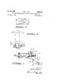
Figure 2 is a frontal elevational view of the spiral wire applying device;
Figure 3 is a plan view of the mechanism shown in Figure 2; and
Figure 4 is a cross-sectional and partially schematic view of the spiral wire applying device together with safety means for stopping the device in cases where the wire is being improperly fed into the pile.
In general terms, the invention comprises a unitary machine which in a plan view has a number of angularly related sections along which material flows in a specific pattern in order to assemble the various elements making up spiral wire bound books or pads. At one end of the machine there are two aligned sections facing each other with a third section extending transversely from their juncture, thus forming a somewhat T-shaped arrangement. Means are provided for supporting rolls of endless paper webs at the two sections forming the head of the T, so that these webs may be fed toward each other and then along the third leg. Damage detection means, printing devices, transverse perforation tools, longitudinal trimming knives, a cross-cutter, piling and counting means are provided along the third machine section. At the outer end of the third section, the machine is provided with a fourth section extending transversely thereto. The
piles are moved alongthe fourth section which is pro 2,973,199 Patented Feb. 28, 1961 ice 2 vided with longitudinal trimming devices and edge perforators.
The discharge end of the fourth section meets the discharge end of an aligned fifth section on which cover sheets are moved in the opposite direction so as to meet the paper piles at the juncture of the fourth and fifth sections. A cover sheet and a bottom sheet are placed on opposite sides of each pile, and the resulting piles flow along a sixth machine section extending transversely to the fourth and fifth sections from the juncture thereof. This sixth section is relatively short, and the seventh section extends transversely from the outer end of the sixth section. The seventh section has means for accurately aligning the perforations in each pile and a knife for dividing each pile transversely into two piles. Cornerrounding means may also be provided at this seventh section.
Two spaced parallel sections, which may be referred to as the eighth and ninth sections, extend transversely from the seventh section, these eighth and ninth sections each being provided with means for applying spiral Wire binders to the piles. Incorporated in the spiral Wire applying devices are safety means for stopping the operation should a wire be improperly fed through the perforations. The completed books or pads are then delivered to the outer ends of these sections.
Referring more particularly to the drawings, Figure 1 shows first and second sections A and B facing each other at one end of the machine, these sections being in alignment and being provided with means for carrying two paper rolls 1 and 2. While one of these two rolls may be used as a standby roll, it may optionally be employed together with the other one in parallel action with a view to doubling the rate of production for the same size machine. The main drive (not shown) of the machine may be located adjacent sections A and B. The width of paper webs in rolls 1 and 2 is preferably twice the desired final height of the pads.
A third section C extends transversely from the juncture of sections A and B, with means 1a, 2a being provided at the juncture of sections A and B for causing the paper webs to run along section C. On section C, a photoelectric cell device schematically shown at 3 is provided so that such damage as holes or tears in the paper webs may be detected. Four printing devices 4 are arranged on each side of the paper webs on section C of the machine, which devices can alternatively be used for aniline or intaglio printing. If only one paper Web is being conveyed from either roll 1 or 2 through the machine, all eight printing devices can be employed for this single paper web, that is, four printing devices each on both sides. If paper webs are being conveyed simultaneously from the two rolls 1 and 2, only four printing devices can be employed for each web, that is, two printing devices each on both sides of each paper web. The printing devices may be used to print, for example, longitudinal and transverse lines.
After the printing the paper may, if required, be provided with a stroke perforation performed by a tool 5 of a cross-cutter type, the cutting edge of which is provided with a series of small milled slots corresponding with the pitch of the perforating strokes to provide the spaces between the perforating strokes. After this operation, the paper web is trimmed longitudinally along its edges by means of circular knives 6 provided on section C. This is followed by cross-cutting of the paper web by means of a cross-cutter 7 at the outer end of section C. The individual sheets thus produced are stacked into piles by a collecting and counting device shown schematically at 8.
So far the manufacturing process described above will have been an uninterrupted flow process. The subsequent operations are performed in rhythmic phases which naturally must be timed with the productional flow in order to simplify the central drive. A fourth machine section D extends transversely from the discharge end of section C, this change in flow direction resulting in a basic simplification of the entire arrangement as will become apparent from the subsequent description.
The sheet piles are conveyed along section D to a cutting device 9 which trims the two longitudinal sides of the pile. This is done in the running direction of the piles on section D as a result of the previous alteration in the direction of conveyance, so that the sheets to be cut need not be passed under the trimming knives.
Assuming that the piles are to be used for the manufacture of ring notebooks, a station 10 is provided atwhich ring book perforations, usually six in number, may be applied to one longitudinal edge of the pile. However, for the usual operation in which spiral wire bound piles are being manufactured, station 10 will be omitted, and the conventional perforation will be provided. These perforations are made at station 11 along one edge of the pile by means of a comb-like tool consisting of individual punching dies which successively increase in length so as to act one after the other, thus reducing the required force and the general effort required in the perforating process. The punching dies are preferably hollow-ground at their cutting edges to form two lips of unequal length so that each die will perform its punching action in successive stages, thus further reducing the stress. Such a perforating device, shown schematically atstation 11, is capable of perforating a pile of twenty sheets quite satisfactorily; the drive is imparted to the device by a special motor coupled with a flywheel and running continuously. The perforating process is activated by means of a clutch which is engaged and disengaged from the main drive of the machine by means of a control cam. After perforations at station 11 have been performed, several plies may be collected at the next station 12, depending upon the desired total thickness of each book or pad.
Station 12 marks the end of what may be regarded as a first operational stage of the machine, including sections A, B, C and D. The resulting piles are now joined by book covers which are stored at a fifth section E which is generally aligned with section D but which feeds the covers in the opposite direction. The book covers may comprise cover and bottom sheets consisting of cardboard or pasteboard which have been previously cut to size and are piled at the left-hand end of section B as seen in Figure 1. For example, a sheet pile 13 comprising cover sheets and a sheet pile 14 comprising bottom sheets may be piled at section E, these sheets carrying printed matter if required. One cover and one bottom sheet each is conveyed at each operation from stackst 13, 14 toward a station 15, where the two sheets are simultaneously perforated in the same manner in which the paper pile in section D is perforated at station 11.
At this stage, the sheet pile and the cover sheets meet at the junction of machine sections D and E, and by means of a suitable device (not shown) the cover sheet is placed above, and the bottom sheet below, the sheet pile.
A sixth section F is provided, this section of the machine being relatively short and extending transversely from the juncture of sections D and E. Extending transversely from the outer end of section F is a seventh section G, this section being roughly parallel with section B as seen in Figure 1. After a brief conveyance on section F, the covered piles again change their direction of movement onto section G. A station 16 is provided at the first part of section G where the sheet piles are accurately aligned with respect to their perforations in order to prevent difiiculty in the later insertion of the spiral wire. The aligning process at station 16 is perforned by the action of two oppositely removable rake-like members which have pegs staggered axially. More particularly, one rake may introduce its pegs from above into the first,
4 Y third, fifth, etc. hole while the other rake inserts its pegs from below into the second, fourth, sixth, etc. hole. The ends of the pegs are conically shaped, thus facilitating their introduction into the perforations and rendering alignment of all holes in the pile easier and more accurate. In conformity with the arcuate movement of the .rakes, the vertically arranged holes in the various sheets are converted into slightly arcuate passages, which arraugement will facilitate the later insertion of the spiral wire.
At the next station 17 of section G, a knife moving transversely to the direction of conveyance divides the piles at the center, thus producing two piles each of which is of a desired book height, these piles being conveyed at a correspondingly faster rate of feed. At an other station 18 on section G, the corners of the piles may be rounded in a conventional manner.
The outer end of section G is provided with a short section H extending therefrom, this section comprising a special table 19 for receiving piles which are unbound owing to failure of the binding devices. Such piles may be passed once more into the operational cycle. Two sections I and K are provided which branch off transversely from section G in parallel relation with each other. These sections may be regarded as the eighth and ninth sections of the machine and receive individual piles from section G.
On sections I and K, trimming and aligning stations 20 are provided in order to adjust the pad to the radial curvature of the spiral wire. This may be performed by displacing the cover sheet and bottom sheet toward the pile center with the aid of two rakes (not shown) which are operated similarly to those described with respect to station 11.
After this operation has taken place on sections I and K, the piles are fed to stations 21 at which are located wire binding devices. At these stations, the individual piles are accurately and firmly positioned with respect to stops which are adapted to provide fixed locations for the introduction of the spiral wires. One of the spiral wire applying devices is shown in detail in Figures 2, 3 and 4. The binder comprises a smooth steel wire 22 which is taken in a coiled condition from a storage unit such as a circular bin standing beside the device. The torsional stresses produced in the wire as it is removed from the storage unit are eliminated by a straightening device (not shown) so that the wire is passed on to the winding device in an unstressed condition. The latter device comprises a rotating mandrel 23 which is disposed between and acts against two steel rollers 24 provided with circumferential slots 25 spaced apart the same distance as the perforations in the pile. As seen best in Figure 4, the foremost slot 25 of each roller is shallower than the others and acts as the driving slot, the other slots acting as guides for the spiral wire 26 which is formed by the rotation of mandrel 23. The pitch of the spiral wire is determined not only by the spacing of slots 25 on steel rollers 24, but also by the angle of incidence with which the straightened wire 22 approaches mandrel 23. By changing this angle of incidence and by replacing the steel rollers by others having a different slot arrangement, spiral wires having other pitches than that shown may be produced.
Positioned forwardly of mandrel 23 as seen in Figure '4 (that is, between the mandrel and the conveyor for the sheet piles) is a guide member 27 for the spiral wire. This guide is mounted in a fixed position and provided with a slot for the spiral wire, as seen best in Figure 3.
A sector of about degrees is removed from this arcuately shaped guide member. When. the spiral wire leaves this sector, it will expand slightly, that is, about 0.5 millimeter, in its diameter. As this occurs naturally on one side only, this guide member must be arranged eccentrically with respect to the axis of mandrel 23; As spiral 'wire 26 leaves guide member 27, it enters the pad perforations which, as mentioned above, are positioned in a fixed manner at stations 21 of sections I and K. In order to aid the threading of spiral wire 26, three rollers (not shown) are provided at each station 21. These rollers may be swung toward the pad, the twolower rollers guiding the spiral wire while the top roller imparts a slight oscillation or vibration to the wire which facilitates its initial insertion into the perforations.
Since there is no completely positive control of position between spiral wire 26 and the pad perforations, it is impossible to prevent the possibility of the starting end of the spiral wire becoming jamrned in the paper due to some deficiency in the perforations, thus preventing further progress of the spiral wire. A tangle would thus result if mandrel 23 continued to advance the wire uninterruptedly, and this jamming would be difiicult and troublesome to remove and might even cause damage to the machine. In accordance with the present invention, a relatively simple safety device is provided to avoid such an occurrence.
More particularly, when the spiral wire meets an obstacle at its forward end, its diameter will enlarge owing to the continuing thrust applied by the rotation of mandrel 23. As a result of this enlargement in diameter, the frictional force between the spiral wire and mandrel 23 will be eliminated, thus halting the feed. The pad thus affected will become a reject, to be placed on table 19.
As an alternative or additional embodiment of the safety device, operating electrically, an abutment 28 may be provided adjacent the mandrel, this abutment being movable in a direction transverse to the mandrel axis. When the Wire diameter expands as a result of an obstacle, spiral wire 26 will be brought into contact with abutment 28 which is electrically connected to a low-voltage relay 29. One side of a low-voltage power source 31 may be connected by a conduit 32 to the other end of relay 29. The other side of voltage source 31 is connected by a conduit 33 to wire 22 so that when the expanding spiral wire engages abutment 28, relay 29 will be energized. This will move a contact 34 closing the circuit between a pair of conduits 35 and 36 which are I in series with a power source 37. A solenoid 38 which is also in series with these conduits is thus energized to actuate an appropriate element 39 which will interrupt the spiral wire manufacturing process.
After the pad has been bound, the spiral wire is cut off at its point of entrance into the pad and the projecting end, if any, at the point of exit is trimmed. To deliver the completed books or pads, one pad will be deposited at the outer ends of sections I and K in one direction, as indicated by the reference numeral 41), while the next pad is turned 180 degrees as indicated at 41 and placed on the first pad, in order to prevent the spiral binder of one pad from becoming entangled with that of the next, which might prove annoying when the pads are being packed.
While it will be apparent that the preferred embodiments of the invention disclosed are well calculated to fulfill the objects above stated, it will be appreciated that the invention is susceptible to modification, variation and change without departing from the proper scope or fair meaning of the subjoined claims.
What is claimed is:
1. In a machine for the manufacture of spiral wire bound pads made of endless paper webs, first and second machine sections in conjoined and opposed relation adapted to support and feed two endless paper webs toward each other, a third machine section extending transversely from the juncture of said first two sections and adapted to receive paper webs moving therealong from said juncture, said third section being further adapted to accommodate printing, longitudinal trimming, transverse cutting, piling and counting means, a fourth machine section extending transversely from the discharge end of said third machine section to one side thereof, said fourth machine section being adapted to accommodate longitudinal trimming means and perforating means for the pads received from said third section, a fifth machine section in conjoined and opposed relation with said fourth machine section, said fifth machine section being adapted to store cover and botton sheets for said pads, the juncture between the discharge ends of said fourth and fifth machine sections being adapted to accommodate means for placing said cover bottom sheets on opposite sides of said pads, a sixth machine section extending transversely from the juncture of said fourth and fifth sections, a seventh machine section extending transversely frorn the discharge end of said sixth machine section to one side thereof, said seventh machine section being adapted to support means for aligning the pad perforations and for transversely dividing said pads in equal halves, and eighth and ninth machine sections extending transversely in spaced parallel relation from the discharge end of said seventh machine section to one side thereof, said eighth and ninth machine sections each being adapted to accommodate spiral wire binding means for said pads.
2. The combination according to claim 1, saidfirst and second sections being provided with means for unwinding said two paper webs and for changing the direction of movement of said paper webs to move along said third section.
3. The combination according to claim 1, said fourth section being provided with means for longitudinally trimming said piles, means for perforating the longitudinal edges of said piles, and means for collecting a plurality of piles into a single pile, said means being adapted to operate in rhythmically successive stages.
4. The combination according to claim 1, said fifth section being provided with means for removing cover and bottom sheets from stacks, perforating said cover and bottom sheets, and placing said cover and bottom sheets on opposite sides of said pads.
5. The combination according to claim 1, said seventh machine section being provided with means for aligning the sheets of each paper pad for the reception of a spiral wire binder, and means for transversely dividing each pad into two parts.
6. The combination according to-clairn 1, further provided with a table adjacent the discharge end of said seventh section, said table being adapted to receive un= bound pads.
References Cited in the file of this patent UNITED STATES PATENTS
Priority Applications (1)
| Application Number | Priority Date | Filing Date | Title |
|---|---|---|---|
| US736190A US2973199A (en) | 1958-05-19 | 1958-05-19 | Machine for manufacturing pads bound with a spiral wire |
Applications Claiming Priority (1)
| Application Number | Priority Date | Filing Date | Title |
|---|---|---|---|
| US736190A US2973199A (en) | 1958-05-19 | 1958-05-19 | Machine for manufacturing pads bound with a spiral wire |
Publications (1)
| Publication Number | Publication Date |
|---|---|
| US2973199A true US2973199A (en) | 1961-02-28 |
Family
ID=24958873
Family Applications (1)
| Application Number | Title | Priority Date | Filing Date |
|---|---|---|---|
| US736190A Expired - Lifetime US2973199A (en) | 1958-05-19 | 1958-05-19 | Machine for manufacturing pads bound with a spiral wire |
Country Status (1)
| Country | Link |
|---|---|
| US (1) | US2973199A (en) |
Cited By (5)
| Publication number | Priority date | Publication date | Assignee | Title |
|---|---|---|---|---|
| US4129913A (en) * | 1977-08-11 | 1978-12-19 | Hans Sickinger Co. | Arrangement for perforating and spiral binding of relatively thick groups of sheets |
| FR2415542A1 (en) * | 1978-01-28 | 1979-08-24 | Bielomatik Leuze & Co | DEVICE AND METHOD FOR BINDING STACKS OF SHEETS BY MEANS OF A SPIRAL, A COMB OR THE LIKE |
| US4466603A (en) * | 1980-05-17 | 1984-08-21 | Bielomatik Leuze Gmbh + Co. | Methods and apparatus for producing stacks of sheets |
| US4611741A (en) * | 1985-01-24 | 1986-09-16 | Eastman Kodak Company | Booklet finishing apparatus |
| US6036423A (en) * | 1998-10-23 | 2000-03-14 | Westra; Michael A. | Coil inserter for binding a stack of sheets together |
Citations (3)
| Publication number | Priority date | Publication date | Assignee | Title |
|---|---|---|---|---|
| US263745A (en) * | 1882-09-05 | Pttchs | ||
| US1010677A (en) * | 1909-04-02 | 1911-12-05 | Alfred C North | Sales-book making and printing machine. |
| US2132827A (en) * | 1937-06-04 | 1938-10-11 | Meisel Press Mfg Company | Printing press |
-
1958
- 1958-05-19 US US736190A patent/US2973199A/en not_active Expired - Lifetime
Patent Citations (3)
| Publication number | Priority date | Publication date | Assignee | Title |
|---|---|---|---|---|
| US263745A (en) * | 1882-09-05 | Pttchs | ||
| US1010677A (en) * | 1909-04-02 | 1911-12-05 | Alfred C North | Sales-book making and printing machine. |
| US2132827A (en) * | 1937-06-04 | 1938-10-11 | Meisel Press Mfg Company | Printing press |
Cited By (6)
| Publication number | Priority date | Publication date | Assignee | Title |
|---|---|---|---|---|
| US4129913A (en) * | 1977-08-11 | 1978-12-19 | Hans Sickinger Co. | Arrangement for perforating and spiral binding of relatively thick groups of sheets |
| FR2415542A1 (en) * | 1978-01-28 | 1979-08-24 | Bielomatik Leuze & Co | DEVICE AND METHOD FOR BINDING STACKS OF SHEETS BY MEANS OF A SPIRAL, A COMB OR THE LIKE |
| US4237568A (en) * | 1978-01-28 | 1980-12-09 | Bielomatik Leuze Gmbh & Co. | Apparatus and method for the binding of stacks of sheets |
| US4466603A (en) * | 1980-05-17 | 1984-08-21 | Bielomatik Leuze Gmbh + Co. | Methods and apparatus for producing stacks of sheets |
| US4611741A (en) * | 1985-01-24 | 1986-09-16 | Eastman Kodak Company | Booklet finishing apparatus |
| US6036423A (en) * | 1998-10-23 | 2000-03-14 | Westra; Michael A. | Coil inserter for binding a stack of sheets together |
Similar Documents
| Publication | Publication Date | Title |
|---|---|---|
| US5348527A (en) | Apparatus for cutting and stacking a multi-form web | |
| US4408755A (en) | Method and apparatus for forming multi-sheet printed products, especially newspapers and magazines | |
| US4349185A (en) | Folding apparatus | |
| US3966185A (en) | Book making | |
| US4408754A (en) | Method and apparatus for gathering together sheets or the like into multi-sheet printed products, especially newspapers and magazines | |
| US3884102A (en) | Three knife trimming machine | |
| CN100486819C (en) | Binding device | |
| US4046366A (en) | Method for producing books | |
| US4073485A (en) | Apparatus for making multiple page printed booklets | |
| US6139003A (en) | Process and device for producing multi-layered newspaper products with a tabloid section | |
| US6010122A (en) | Method and apparatus for producing high page count signatures | |
| JP3326119B2 (en) | Bookbinding device | |
| US4050686A (en) | Sheet or signature feeding machine and method | |
| US3826290A (en) | Coil binding machine | |
| US2973199A (en) | Machine for manufacturing pads bound with a spiral wire | |
| US8002257B2 (en) | Web conversion and collating apparatus and method | |
| US3231261A (en) | Method of and means for fabricating booklets from continuous webs | |
| US2873113A (en) | Apparatus for producing magazines and the like | |
| US3937452A (en) | Method and apparatus for manufacturing continuous form sets | |
| JP3813443B2 (en) | A collation binding machine and method for creating a thumbtab index in a stapled print or other book. | |
| US2769496A (en) | Rotary cutting die for perforating signatures | |
| US3237934A (en) | Method and apparatus for making books | |
| US1200758A (en) | Printing and delivery mechanism. | |
| US3427655A (en) | Method for producing collated printed books | |
| US3370843A (en) | Method and apparatus for producing printed publications |